EP2012387B1 - Power storage apparatus - Google Patents
Power storage apparatus Download PDFInfo
- Publication number
- EP2012387B1 EP2012387B1 EP06732285.9A EP06732285A EP2012387B1 EP 2012387 B1 EP2012387 B1 EP 2012387B1 EP 06732285 A EP06732285 A EP 06732285A EP 2012387 B1 EP2012387 B1 EP 2012387B1
- Authority
- EP
- European Patent Office
- Prior art keywords
- power storage
- housing
- storage modules
- opening
- storage area
- Prior art date
- Legal status (The legal status is an assumption and is not a legal conclusion. Google has not performed a legal analysis and makes no representation as to the accuracy of the status listed.)
- Expired - Lifetime
Links
Images





Classifications
-
- H—ELECTRICITY
- H01—ELECTRIC ELEMENTS
- H01M—PROCESSES OR MEANS, e.g. BATTERIES, FOR THE DIRECT CONVERSION OF CHEMICAL ENERGY INTO ELECTRICAL ENERGY
- H01M10/00—Secondary cells; Manufacture thereof
- H01M10/42—Methods or arrangements for servicing or maintenance of secondary cells or secondary half-cells
- H01M10/4207—Methods or arrangements for servicing or maintenance of secondary cells or secondary half-cells for several batteries or cells simultaneously or sequentially
-
- B—PERFORMING OPERATIONS; TRANSPORTING
- B60—VEHICLES IN GENERAL
- B60L—PROPULSION OF ELECTRICALLY-PROPELLED VEHICLES; SUPPLYING ELECTRIC POWER FOR AUXILIARY EQUIPMENT OF ELECTRICALLY-PROPELLED VEHICLES; ELECTRODYNAMIC BRAKE SYSTEMS FOR VEHICLES IN GENERAL; MAGNETIC SUSPENSION OR LEVITATION FOR VEHICLES; MONITORING OPERATING VARIABLES OF ELECTRICALLY-PROPELLED VEHICLES; ELECTRIC SAFETY DEVICES FOR ELECTRICALLY-PROPELLED VEHICLES
- B60L7/00—Electrodynamic brake systems for vehicles in general
- B60L7/22—Dynamic electric resistor braking, combined with dynamic electric regenerative braking
-
- B—PERFORMING OPERATIONS; TRANSPORTING
- B60—VEHICLES IN GENERAL
- B60L—PROPULSION OF ELECTRICALLY-PROPELLED VEHICLES; SUPPLYING ELECTRIC POWER FOR AUXILIARY EQUIPMENT OF ELECTRICALLY-PROPELLED VEHICLES; ELECTRODYNAMIC BRAKE SYSTEMS FOR VEHICLES IN GENERAL; MAGNETIC SUSPENSION OR LEVITATION FOR VEHICLES; MONITORING OPERATING VARIABLES OF ELECTRICALLY-PROPELLED VEHICLES; ELECTRIC SAFETY DEVICES FOR ELECTRICALLY-PROPELLED VEHICLES
- B60L3/00—Electric devices on electrically-propelled vehicles for safety purposes; Monitoring operating variables, e.g. speed, deceleration or energy consumption
- B60L3/0023—Detecting, eliminating, remedying or compensating for drive train abnormalities, e.g. failures within the drive train
- B60L3/0046—Detecting, eliminating, remedying or compensating for drive train abnormalities, e.g. failures within the drive train relating to electric energy storage systems, e.g. batteries or capacitors
-
- B—PERFORMING OPERATIONS; TRANSPORTING
- B60—VEHICLES IN GENERAL
- B60L—PROPULSION OF ELECTRICALLY-PROPELLED VEHICLES; SUPPLYING ELECTRIC POWER FOR AUXILIARY EQUIPMENT OF ELECTRICALLY-PROPELLED VEHICLES; ELECTRODYNAMIC BRAKE SYSTEMS FOR VEHICLES IN GENERAL; MAGNETIC SUSPENSION OR LEVITATION FOR VEHICLES; MONITORING OPERATING VARIABLES OF ELECTRICALLY-PROPELLED VEHICLES; ELECTRIC SAFETY DEVICES FOR ELECTRICALLY-PROPELLED VEHICLES
- B60L3/00—Electric devices on electrically-propelled vehicles for safety purposes; Monitoring operating variables, e.g. speed, deceleration or energy consumption
- B60L3/0023—Detecting, eliminating, remedying or compensating for drive train abnormalities, e.g. failures within the drive train
- B60L3/0069—Detecting, eliminating, remedying or compensating for drive train abnormalities, e.g. failures within the drive train relating to the isolation, e.g. ground fault or leak current
-
- B—PERFORMING OPERATIONS; TRANSPORTING
- B60—VEHICLES IN GENERAL
- B60L—PROPULSION OF ELECTRICALLY-PROPELLED VEHICLES; SUPPLYING ELECTRIC POWER FOR AUXILIARY EQUIPMENT OF ELECTRICALLY-PROPELLED VEHICLES; ELECTRODYNAMIC BRAKE SYSTEMS FOR VEHICLES IN GENERAL; MAGNETIC SUSPENSION OR LEVITATION FOR VEHICLES; MONITORING OPERATING VARIABLES OF ELECTRICALLY-PROPELLED VEHICLES; ELECTRIC SAFETY DEVICES FOR ELECTRICALLY-PROPELLED VEHICLES
- B60L50/00—Electric propulsion with power supplied within the vehicle
- B60L50/50—Electric propulsion with power supplied within the vehicle using propulsion power supplied by batteries or fuel cells
- B60L50/60—Electric propulsion with power supplied within the vehicle using propulsion power supplied by batteries or fuel cells using power supplied by batteries
- B60L50/64—Constructional details of batteries specially adapted for electric vehicles
-
- B—PERFORMING OPERATIONS; TRANSPORTING
- B60—VEHICLES IN GENERAL
- B60L—PROPULSION OF ELECTRICALLY-PROPELLED VEHICLES; SUPPLYING ELECTRIC POWER FOR AUXILIARY EQUIPMENT OF ELECTRICALLY-PROPELLED VEHICLES; ELECTRODYNAMIC BRAKE SYSTEMS FOR VEHICLES IN GENERAL; MAGNETIC SUSPENSION OR LEVITATION FOR VEHICLES; MONITORING OPERATING VARIABLES OF ELECTRICALLY-PROPELLED VEHICLES; ELECTRIC SAFETY DEVICES FOR ELECTRICALLY-PROPELLED VEHICLES
- B60L58/00—Methods or circuit arrangements for monitoring or controlling batteries or fuel cells, specially adapted for electric vehicles
- B60L58/10—Methods or circuit arrangements for monitoring or controlling batteries or fuel cells, specially adapted for electric vehicles for monitoring or controlling batteries
- B60L58/18—Methods or circuit arrangements for monitoring or controlling batteries or fuel cells, specially adapted for electric vehicles for monitoring or controlling batteries of two or more battery modules
-
- B—PERFORMING OPERATIONS; TRANSPORTING
- B60—VEHICLES IN GENERAL
- B60L—PROPULSION OF ELECTRICALLY-PROPELLED VEHICLES; SUPPLYING ELECTRIC POWER FOR AUXILIARY EQUIPMENT OF ELECTRICALLY-PROPELLED VEHICLES; ELECTRODYNAMIC BRAKE SYSTEMS FOR VEHICLES IN GENERAL; MAGNETIC SUSPENSION OR LEVITATION FOR VEHICLES; MONITORING OPERATING VARIABLES OF ELECTRICALLY-PROPELLED VEHICLES; ELECTRIC SAFETY DEVICES FOR ELECTRICALLY-PROPELLED VEHICLES
- B60L58/00—Methods or circuit arrangements for monitoring or controlling batteries or fuel cells, specially adapted for electric vehicles
- B60L58/10—Methods or circuit arrangements for monitoring or controlling batteries or fuel cells, specially adapted for electric vehicles for monitoring or controlling batteries
- B60L58/24—Methods or circuit arrangements for monitoring or controlling batteries or fuel cells, specially adapted for electric vehicles for monitoring or controlling batteries for controlling the temperature of batteries
- B60L58/26—Methods or circuit arrangements for monitoring or controlling batteries or fuel cells, specially adapted for electric vehicles for monitoring or controlling batteries for controlling the temperature of batteries by cooling
-
- B—PERFORMING OPERATIONS; TRANSPORTING
- B60—VEHICLES IN GENERAL
- B60R—VEHICLES, VEHICLE FITTINGS, OR VEHICLE PARTS, NOT OTHERWISE PROVIDED FOR
- B60R16/00—Electric or fluid circuits specially adapted for vehicles and not otherwise provided for; Arrangement of elements of electric or fluid circuits specially adapted for vehicles and not otherwise provided for
- B60R16/02—Electric or fluid circuits specially adapted for vehicles and not otherwise provided for; Arrangement of elements of electric or fluid circuits specially adapted for vehicles and not otherwise provided for electric constitutive elements
- B60R16/04—Arrangement of batteries
-
- H—ELECTRICITY
- H01—ELECTRIC ELEMENTS
- H01M—PROCESSES OR MEANS, e.g. BATTERIES, FOR THE DIRECT CONVERSION OF CHEMICAL ENERGY INTO ELECTRICAL ENERGY
- H01M10/00—Secondary cells; Manufacture thereof
- H01M10/42—Methods or arrangements for servicing or maintenance of secondary cells or secondary half-cells
- H01M10/44—Methods for charging or discharging
- H01M10/441—Methods for charging or discharging for several batteries or cells simultaneously or sequentially
-
- H—ELECTRICITY
- H01—ELECTRIC ELEMENTS
- H01M—PROCESSES OR MEANS, e.g. BATTERIES, FOR THE DIRECT CONVERSION OF CHEMICAL ENERGY INTO ELECTRICAL ENERGY
- H01M50/00—Constructional details or processes of manufacture of the non-active parts of electrochemical cells other than fuel cells, e.g. hybrid cells
- H01M50/20—Mountings; Secondary casings or frames; Racks, modules or packs; Suspension devices; Shock absorbers; Transport or carrying devices; Holders
- H01M50/204—Racks, modules or packs for multiple batteries or multiple cells
-
- H—ELECTRICITY
- H01—ELECTRIC ELEMENTS
- H01M—PROCESSES OR MEANS, e.g. BATTERIES, FOR THE DIRECT CONVERSION OF CHEMICAL ENERGY INTO ELECTRICAL ENERGY
- H01M50/00—Constructional details or processes of manufacture of the non-active parts of electrochemical cells other than fuel cells, e.g. hybrid cells
- H01M50/20—Mountings; Secondary casings or frames; Racks, modules or packs; Suspension devices; Shock absorbers; Transport or carrying devices; Holders
- H01M50/262—Mountings; Secondary casings or frames; Racks, modules or packs; Suspension devices; Shock absorbers; Transport or carrying devices; Holders with fastening means, e.g. locks
-
- H—ELECTRICITY
- H01—ELECTRIC ELEMENTS
- H01M—PROCESSES OR MEANS, e.g. BATTERIES, FOR THE DIRECT CONVERSION OF CHEMICAL ENERGY INTO ELECTRICAL ENERGY
- H01M50/00—Constructional details or processes of manufacture of the non-active parts of electrochemical cells other than fuel cells, e.g. hybrid cells
- H01M50/20—Mountings; Secondary casings or frames; Racks, modules or packs; Suspension devices; Shock absorbers; Transport or carrying devices; Holders
- H01M50/271—Lids or covers for the racks or secondary casings
-
- H—ELECTRICITY
- H01—ELECTRIC ELEMENTS
- H01M—PROCESSES OR MEANS, e.g. BATTERIES, FOR THE DIRECT CONVERSION OF CHEMICAL ENERGY INTO ELECTRICAL ENERGY
- H01M50/00—Constructional details or processes of manufacture of the non-active parts of electrochemical cells other than fuel cells, e.g. hybrid cells
- H01M50/20—Mountings; Secondary casings or frames; Racks, modules or packs; Suspension devices; Shock absorbers; Transport or carrying devices; Holders
- H01M50/289—Mountings; Secondary casings or frames; Racks, modules or packs; Suspension devices; Shock absorbers; Transport or carrying devices; Holders characterised by spacing elements or positioning means within frames, racks or packs
-
- B—PERFORMING OPERATIONS; TRANSPORTING
- B60—VEHICLES IN GENERAL
- B60L—PROPULSION OF ELECTRICALLY-PROPELLED VEHICLES; SUPPLYING ELECTRIC POWER FOR AUXILIARY EQUIPMENT OF ELECTRICALLY-PROPELLED VEHICLES; ELECTRODYNAMIC BRAKE SYSTEMS FOR VEHICLES IN GENERAL; MAGNETIC SUSPENSION OR LEVITATION FOR VEHICLES; MONITORING OPERATING VARIABLES OF ELECTRICALLY-PROPELLED VEHICLES; ELECTRIC SAFETY DEVICES FOR ELECTRICALLY-PROPELLED VEHICLES
- B60L2200/00—Type of vehicles
- B60L2200/26—Rail vehicles
-
- Y—GENERAL TAGGING OF NEW TECHNOLOGICAL DEVELOPMENTS; GENERAL TAGGING OF CROSS-SECTIONAL TECHNOLOGIES SPANNING OVER SEVERAL SECTIONS OF THE IPC; TECHNICAL SUBJECTS COVERED BY FORMER USPC CROSS-REFERENCE ART COLLECTIONS [XRACs] AND DIGESTS
- Y02—TECHNOLOGIES OR APPLICATIONS FOR MITIGATION OR ADAPTATION AGAINST CLIMATE CHANGE
- Y02E—REDUCTION OF GREENHOUSE GAS [GHG] EMISSIONS, RELATED TO ENERGY GENERATION, TRANSMISSION OR DISTRIBUTION
- Y02E60/00—Enabling technologies; Technologies with a potential or indirect contribution to GHG emissions mitigation
- Y02E60/10—Energy storage using batteries
-
- Y—GENERAL TAGGING OF NEW TECHNOLOGICAL DEVELOPMENTS; GENERAL TAGGING OF CROSS-SECTIONAL TECHNOLOGIES SPANNING OVER SEVERAL SECTIONS OF THE IPC; TECHNICAL SUBJECTS COVERED BY FORMER USPC CROSS-REFERENCE ART COLLECTIONS [XRACs] AND DIGESTS
- Y02—TECHNOLOGIES OR APPLICATIONS FOR MITIGATION OR ADAPTATION AGAINST CLIMATE CHANGE
- Y02T—CLIMATE CHANGE MITIGATION TECHNOLOGIES RELATED TO TRANSPORTATION
- Y02T10/00—Road transport of goods or passengers
- Y02T10/60—Other road transportation technologies with climate change mitigation effect
- Y02T10/70—Energy storage systems for electromobility, e.g. batteries
Definitions
- the present invention relates to a power-storage apparatus that stores and discharges DC electric power.
- a power storage system in a power storage apparatus being one component element of the power storage system, there are located power storage modules to store electric power, and electrical parts of, e.g., a switching protective device section for protecting or making/breaking circuits, and further there are provided a main circuit wiring for a main circuit and a control circuit wiring for a control circuit for providing connection between them.
- Document US 6 197 444 B1 discloses a battery case comprising a pair of case members joined together along a seam to form a housing.
- Each case member includes a pair of sidewalls adapted to define a base surface on which the case rests so as to permit a plurality of resting orientations of the battery case.
- the seam is positioned above the lowermost base surface of the casing to contain any leaked battery acid regardless of case orientation.
- the battery case includes supports for supporting the lower surface of the battery above any leaked acid, as well as partitions that define a discrete cavity for each battery to isolate the battery from an adjacent battery that may be leaking.
- Document US 2002/102457 A1 also discloses a multi-cell structure battery which comprises a plurality of columnar cells accommodated in a casing, bus bars to connect respective terminals of the cells, signal transmitting wires to connect the respective cells to an external device, a cell holder to hold the cells, and a covering fixed to the cell holder so as to oppose against the terminals of the cells.
- the bus bars are disposed on an inner surface of the covering opposed to the terminals of the cells and the signal transmitting wires being disposed in an outer surface of the covering.
- US 6 401 946 B1 discloses an integral spill containment system for a composite battery stand having a shelf adapted to receive at least one battery subject to leaking electrolyte.
- the system includes an aperture, located in the shelf, adapted to channel the electrolyte away from the shelf and a removable tray, located under the shelf and within a footprint of the battery stand, which is adapted to collect the electrolyte via the aperture thereby containing the electrolyte within the footprint of the battery stand.
- power storage modules require a periodic inspection of whether a leakage of an electrolyte in the internal part is present or absent, or whether apparent abnormalities are present or absent; and moreover since they have a product life of about 5 to 10 years, the power storage modules have to be constructed taking the efficiency of inspection or replacing works into consideration.
- Patent Document 1 As a prior art related to the internal construction of a power storage apparatus, as shown in Patent Document 1, a device related to an insulating method has been proposed. However, there has been no disclosure related to the layout of each part and the structure of a housing useful for solving the problems as discussed above.
- the invention has an object of providing a power storage apparatus capable of making it easy to execute inspection or replacing works of power storage modules, as well as making it possible to prevent an electric shock at the time of working, and capable of reliably performing a protective operation such as an interruption of circuits without any damage to the electrical parts of, e.g., a switching protective device section or a control section, or a main circuit wiring or a control circuit wiring even at the time of occurrence of a short-circuit fault or at the time of breakdown of power storage modules.
- a protective operation such as an interruption of circuits without any damage to the electrical parts of, e.g., a switching protective device section or a control section, or a main circuit wiring or a control circuit wiring even at the time of occurrence of a short-circuit fault or at the time of breakdown of power storage modules.
- the present invention provides a power storage apparatus in which a plurality of connected power storage modules is mounted, and which can charge or discharge electric power, according to independent claim 1. Further embodiments of the invention can be realised according to the corresponding dependent claims.
- the power storage apparatus of the invention it is possible to prevent an electric shock at working.
- a protective operation such as an interruption of circuit without damage to the electrical parts of the switching protective device section, the control section and the like, or to the main circuit wiring or the control circuit wiring.
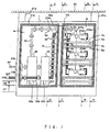
- Fig. 1 is a front elevation (showing a state in which a front cover is opened) of a power storage apparatus according to a first preferred embodiment of the present invention.
- Fig. 2 is a front elevation (showing a state in which the front cover is closed) of the power storage apparatus according to the first embodiment.
- Fig. 3 is a sectional view taken along the line A-A (showing a state in which the front cover is closed) of the power storage apparatus of Fig. 1 .
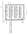
- Fig. 4 is a sectional view taken along the line B-B (showing a state in which the front cover is closed) of the power storage apparatus of Fig. 1 .
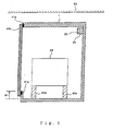
- Fig. 5 is a sectional view taken along the line C-C (showing a state in which the front cover is closed) of the power storage apparatus of Fig. 1 .
- Fig. 6 is a sectional view taken along the line D-D (showing a state in which the front cover is closed) of the power storage apparatus of Fig. 1 .
- main components contained in the power storage apparatus include power storage modules 20a1 to 20a3, 20b1 to 20b3, 20c1 to 20c3 ( Fig. 4 ), a state monitor 30a ( Fig. 1 ), a control circuit wiring 33, main circuit wirings 22P and 22N, a control section 35, and a switching protective device section 23. These components are contained in a housing 1 to form a power storage apparatus.
- the power storage modules are constructed of a plurality of, for example, secondary batteries or electric double layer capacitors connected in series or in parallel.
- the foregoing housing 1 is attached to a car body 50 (for example, under the floor of vehicles) via attachment members 51a, 51b, and 51c.
- the housing 1 and the attachment members 51a, 51 b, 51 c are made of, for example, aluminum, stainless or iron, being any metal.
- the control circuit wiring 33 and the main circuit wirings 22P and 22N are led out of the housing 1, and connected to any apparatus forming an external power storage system such as DC-DC converters, to make the charge or discharge of an electric power while exchanging control signals.
- the control circuit wiring 33 is a bundle of lines constructed of a plurality of control circuit wirings.
- the structural arrangement of the power storage modules 20a1 to 20a3, 20b1 to 20b3, 20c1 to 20c3 is described.
- the power storage modules 20a1 to 20a3, 20b1 to 20b3, 20c1 to 20c3 the basic construction of them is the same.
- the following description is made representatively focusing on the power storage modules 20a1 to 20a3 shown in the uppermost level part of Fig. 1 .
- the housing 1 is partitioned with a partition plate 2, to be divided into a power storage area 1b and a control device area 1a.
- a pallet 4 supported at both sides with guide rails 3a and 3b that are fixed to the housing 1 and the partition plate 2, and the power storage modules 20a1 to 20a3 are mounted thereon ( Figs. 1 and 4 ).
- Under the pallet 4a there is provided an insulating plate 6a supported at both sides with guide rails 5a and 5b that are likewise fixed to the housing 1 and the partition plate 2.
- a state monitor 30a functioning to monitor voltage, current, temperature and the like is provided at the power storage modules 20a1 to 20a3 mounted on the pallet 4. Further, signals from the state monitor 30a are connected to the control circuit wiring 33.
- the partition plate 2 and the guide rails 3a, 3b, 5a, 5b are made of, for example, fiber reinforced plastics, being an insulating plate, or the same metal as that of the housing 1.
- a positive terminal 21Pa and a negative terminal 21Na ( Fig. 1 ), to be in structure of allowing to get electric power. Further, the mass thereof is about several dozens kg, and thus the mass of a pallet 4a on which a plurality of power storage modules are mounted comes to be approximately 100 kg.
- the pallet 4a is made of fiber reinforced plastics or the same metal as that of the housing 1 in order to support the above-mentioned mass.
- the pallet 4a is perforated with holes at such portions not required to have much strength in order to achieve weight reduction, and so as to allow an electrolyte to drip to the insulating plate 6a under the pallet 4a in the case where an electrolyte existing in an internal part of the power storage modules is leaked.
- the insulating plate 6a is a plate, which is made of an electrically insulating substance such as acryl, Bakelite, or reinforced plastics, and which is disposed right below the pallet 4a.
- This insulating plate 6a is not perforated with holes all over the face so as not to allow an electrolyte to pass through but to receive all the electrolyte, to prevent the electrolyte from dripping, e.g., onto the power storage modules at the lower level in the case where the electrolyte is leaked out of the upper power storage modules.
- the mass of the insulating plate 6a is just several kg or so.
- the power storage modules 20a1 to 20a3 along with the pallet 4a it becomes possible to allow the power storage modules 20a1 to 20a3 along with the pallet 4a to slide frontward along the guide rails 3a and 3b to be pulled out.
- the power storage modules are pulled out toward the front of the housing 1, that is, the power storage area 1b, and the inspection or replacing work of the power storage modules is executed.
- the power storage modules are inserted again along with the pallet 4a. In this manner, it is possible to easily execute the inspection or replacing work of the power storage modules.
- the insulating plate 6a in the case of pulling out the power storage modules 20b1 to 20b3 at the lower level along with a pallet, it is possible to prevent any positive or negative terminal thereof from being in contact with the upper pallet 4a. Furthermore, in the case where the power storage modules are broken, and an electrolyte in the internal part is leaked out, it is possible to prevent the electrolyte from dripping onto the other power storage modules at the lower level and leading to expansion of a damage situation.
- any oil is applied or there are provided bearings in order to be less sliding friction and make it easy to pull out the pallet 4a.
- the guide rails 3a and 3b are structured to support the underside of the pallet 4a, to eliminate any displacement in the vertical direction of the pallet 4a, it is preferable that other guide rails are formed at the portion in contact with the top of the pallet 4a to be in construction of guiding the pallet 4a in the vertical direction.
- the power storage modules including those likewise constructed and disposed in each pallet of the middle level and the lower level, are connected in series and in parallel to each other.
- the positive terminal of the power storage module of which the potential is the highest is connected to the main circuit wiring 22P on the positive side, and the negative terminal of the power storage module of which the potential is the lowest is connected to the main circuit wiring 22N on the negative side.
- Fig. 1 schematically shows the wiring providing series-parallel connection between the power storage modules disposed on each pallet of the upper, middle, and lower levels
- the connection lines between each of the levels are located, for example, on the rear side of the housing 1 so as not to impede smooth pulling-out of the pallets 4a and the insulating plates 6a.
- the contacts on the positive and negative sides are formed on the rear side of the housing 1 at each of the upper, middle, and lower levels; and that both of those contacts are brought in an open circuit by pulling out each pallet, and they are brought in a closed circuit upon putting each pallet in storage.
- the power storage modules of pallets are not limited to the construction of three levels and one column, as illustratively shown, but it is preferable to be constructed in other numbers of levels, or to be constructed in a plurality of columns.
- the pallet of a power storage module of the highest potential is disposed at the uppermost level
- the pallet of a power storage module of the lowest potential is disposed at the lowermost level.
- the positive side main circuit wiring 22P and the negative side main circuit wiring 22N from the power storage modules are connected to a switching protective device section 23 of the housing 1 that is a control device area 1a through a lead-through member 22a formed in the partition plate 2, pulled out of the housing 1 from the switching protective device section 23 through a lead-through member 22b, and connected to, e.g., an external DC-DC converter.
- control circuit wiring 33 is connected to a control section 35 of the control device area 1a through a lead-through member 32a formed in the partition plate 2, pulled out of the housing 1, and connected to an external monitoring control section (not shown).
- monitoring control section states of the power storage modules are monitored, and, e.g., the DC-DC converter is controlled.
- control circuit wiring 33 is connected from the control section 35 to the switching protective device section 23, to switch the switching protective device section 23 depending on the states of power storage modules obtained from the monitors 30a. Additionally, the switching protective device section 23 is switched in response to signals from the monitoring section as well.
- Each lead-through member is made of an electrically insulating material, for example, rubber, nylon, or Bakelite.
- the lead-through members 22a and 22b for the positive side main circuit wiring 22P and the negative side main circuit wiring 22N are lead-through members different from the lead-through members 32a and 32b for the control circuit wiring 33. These lead-through members are members for protecting the main circuit wirings 22P and 22N and the control circuit wiring 33 from being in contact with the end face of materials of the housing 1 and the partition plate 2 so as not to be damaged.
- the switching protective device section 23 is a section constructed of devices for interrupting, or making or breaking the circuits, that is formed of fuses, circuit breakers, or ON/OFF switches.
- the control section 35 is a section of controlling operations of, e.g., the circuit breakers or the ON/OFF switches of the switching protective device section 23.
- the partition plate 2 functions to support the pallets 4a on which the power storage modules are mounted, and it is also located for providing separation between the power storage area 1b of the housing 1 in which power storage modules are disposed, and the control device area 1a of the housing 1 in which the switching protective device section 23 and the control section 35 are disposed.
- the main circuit wiring 22P on the positive side and the main circuit wiring 22N on the negative side are fixed to, e.g., the surface of walls of the housing 1 with fixing members 24.
- the control circuit wiring 33 is fixed to, e.g., the surface of walls of the housing 1 with fixing members 34.
- the fixing members are made of insulating materials such as cable ties of Bakelite, vinyl, or Teflon, or metals coated with rubber, which are suitably selected taking strength thereof into consideration.
- the main circuit wirings 22P and 22N need to be fixed forming a rigid structure as compared with the fixation of the control circuit wiring 33.
- the fixing members 24 are to be formed into a rigid structure as compared with the fixing members 34, and are disposed spaced apart from the control circuit wiring 33.
- the lead-through members 22a and 22b for the positive side main circuit wiring 22P and the negative side main circuit wiring 22N are lead-through members different from the lead-through members 32a and 32b for the control circuit wiring 33.
- the bottom of the switching protective device section 23 and the control section 35, with attachment members 40a to 40e, are raised to a higher level further higher by Height H2 than the lower end of openings positioned at height H1 from the bottom in the internal part of the housing 1, that is, the control device area 1a.
- the attachment members 40a to 40e may be made of the same material as that of a partition plate 2.
- the lead-through members 22b and 32b attached to the housing 1 are likewise raised as well.
- H1 the level of height from the bottom in the internal part of the housing 1
- H1 the value of H1 depends on the amount of the electrolyte of the power storage modules, it is preferable to be in the range of several centimeters.
- the underside of the switching protective device section 23 and the control section 35 are disposed at Height H2 from the lower end of the openings, even in the case where the power storage modules are broken and the electrolyte in the internal part flows out, so that an electrolyte may enter the control device area 1a of the switching protective device section 23 and the control section 35 through, e.g., the gap between the partition plate 2 and the housing 1, it is possible to avoid a damage of the switching protective device section 23 and the control section 35 due to the electrolyte.
- the lead-through members 22b and 32b are disposed at Height H2 from the lower end of the openings, even when the power storage modules are broken and the electrolyte in the internal part flows out so that any electrolyte may enter the control device area 1a through, e.g., the gap between the partition plate 2 and the housing 1, it becomes possible to avoid a damage of the positive side main circuit wiring 22P and the negative side main circuit wiring 22N, the control circuit wiring 33, and the lead-through members 22b and 32b due to the electrolyte. Thus, it is possible to prevent the damaged portions from being expanded.
- Gaskets 41 a to 41b are provided around the openings, to be in a construction of allowing each of the control device area 1a and the power storage area 1b to be independently opened or closed with covers 42a and 42b. Since it is constructed such that the cover member is divided into the two pieces of covers 42a and 42b, which can cover the control device area 1a and the power storage area 1b respectively, it becomes possible to detach only one cover of the area to be inspected.
- Fig. 7 is a front view (showing a state in which a front cover is closed) of a power storage apparatus according to a second embodiment.
- This power storage apparatus is intended to be mounted on the floor or on the roof 60 of vehicles, and there are provided at the underside of the housing 1 attachment members 51 d and 51 e.
- the power storage apparatus can be applied to any structure in which the housing 1 is mounted at the underside of the vehicles, in which it is mounted on a roof thereof, or in which it is mounted on the floor in the vehicles.
- Fig. 8 is a schematic sectional view (showing a state in which a front cover is closed) of a power storage apparatus according to a third embodiment.
- Fig. 8 corresponds to Fig. 4 , being a cross-section taken along line B-B of the first embodiment.
- the third embodiment it is intended that power storage modules 20a1 to 20a3, 20b1 to 20b3, 20c1 to 20c3 are effectively cooled.
- the arrows indicate the flow of cooling air.
- the pallets 4a With the holes formed in the pallets 4a1, it is possible to let flow sufficient air also around the power storage modules disposed downstream (for example, 20a3).
- the pallets are located at a plurality of levels as in the first embodiment.
- the cooling air is sucked in through the cover 43, is led to each of the power storage modules through the holes of the pallets of each level, cools each of the power storage modules, and is discharged from the bottom of the housing 1 through the air duct 45.
- the flow of cooling air is not limited to this example, but it is preferable to be constructed such that air is sucked in through other points, and is discharged out of the cover 43.
- the cover mounted onto the openings originally formed in the housing 1 is structured to allow cooling air to pass, so that as to the suction of the cooling air, no air inlet needs to be newly formed at any other position of the housing 1, and thus the strength of the housing 1 is not impaired.
- the power storage modules in the power storage area are forcibly cooled, it is preferable to forcibly cool the control device area.
- first, second, and third embodiments are described to have a construction in which the parts forming a power storage apparatus (power storage modules, switching protective device section, and control section) are contained in the housing 1 dedicated for the power storage apparatus, the power storage apparatus according to the invention is not limited to such embodiments.
- a power storage apparatus to be applied to a power storage system mounted onto railway vehicles.
- the field of application is not limited to such a field of vehicles, but can be applied to various related fields such as a ground-based power storage system in the field of railway, automobiles, elevators, and electric power systems, as a matter or course.
Landscapes
- Engineering & Computer Science (AREA)
- Chemical Kinetics & Catalysis (AREA)
- Electrochemistry (AREA)
- General Chemical & Material Sciences (AREA)
- Chemical & Material Sciences (AREA)
- Power Engineering (AREA)
- Mechanical Engineering (AREA)
- Transportation (AREA)
- Life Sciences & Earth Sciences (AREA)
- Sustainable Development (AREA)
- Sustainable Energy (AREA)
- Manufacturing & Machinery (AREA)
- Battery Mounting, Suspending (AREA)
- Secondary Cells (AREA)
Abstract
Description
- The present invention relates to a power-storage apparatus that stores and discharges DC electric power.
- As is known in the art, a power storage system in which power storage modules such as secondary batteries or electric double layer capacitors are used to enable the charge or discharge of an electric power has been applied to a control device of electric motor vehicles. By this system, excess regenerative electric power generated at the time of braking of the vehicles is stored, and the stored electric power is used at the time of acceleration, thereby making it possible to effectively use a kinetic energy that the vehicles have (for example, Patent Document 1).
- In the case where a power storage system is applied to any control device of electric motor vehicles, in a power storage apparatus being one component element of the power storage system, there are located power storage modules to store electric power, and electrical parts of, e.g., a switching protective device section for protecting or making/breaking circuits, and further there are provided a main circuit wiring for a main circuit and a control circuit wiring for a control circuit for providing connection between them.
- Patent Document 1: Japanese Patent Application Publication (unexamined)
JP-A-2006-14412 - Document
US 6 197 444 B1 discloses a battery case comprising a pair of case members joined together along a seam to form a housing. Each case member includes a pair of sidewalls adapted to define a base surface on which the case rests so as to permit a plurality of resting orientations of the battery case. The seam is positioned above the lowermost base surface of the casing to contain any leaked battery acid regardless of case orientation. Further, the battery case includes supports for supporting the lower surface of the battery above any leaked acid, as well as partitions that define a discrete cavity for each battery to isolate the battery from an adjacent battery that may be leaking. - Document
US 2002/102457 A1 also discloses a multi-cell structure battery which comprises a plurality of columnar cells accommodated in a casing, bus bars to connect respective terminals of the cells, signal transmitting wires to connect the respective cells to an external device, a cell holder to hold the cells, and a covering fixed to the cell holder so as to oppose against the terminals of the cells. The bus bars are disposed on an inner surface of the covering opposed to the terminals of the cells and the signal transmitting wires being disposed in an outer surface of the covering. - Furthermore,
US 6 401 946 B1 discloses an integral spill containment system for a composite battery stand having a shelf adapted to receive at least one battery subject to leaking electrolyte. In one example, the system includes an aperture, located in the shelf, adapted to channel the electrolyte away from the shelf and a removable tray, located under the shelf and within a footprint of the battery stand, which is adapted to collect the electrolyte via the aperture thereby containing the electrolyte within the footprint of the battery stand. - Problems in construction of such a power storage apparatus are as follows.
- First, power storage modules require a periodic inspection of whether a leakage of an electrolyte in the internal part is present or absent, or whether apparent abnormalities are present or absent; and moreover since they have a product life of about 5 to 10 years, the power storage modules have to be constructed taking the efficiency of inspection or replacing works into consideration.
- Furthermore, a large amount of energy needs to be stored in order to drive electric motor vehicles. Thus, a plurality of power storage modules connected in series or in parallel is used, so that voltages at both ends of the plurality of power storage modules connected in series or in parallel come to be higher. Consequently, special considerations need to be paid from the viewpoint of prevention of an electric shock at the time of inspection or replacing works.
- Further, in the case of occurrence of errors such a short-circuit or breakdown at the power storage modules having a large energy or at the power storage apparatus, to avoid the expansion of damage, it is important to reliably activate a protective operation of, e.g., immediately interrupting circuits and reliably disconnecting the power storage modules from the system. Therefore, electrical parts of a switching protective device section, a control section thereof or the like, or a main circuit wiring or a control circuit wiring have to be arranged so as not to impair functions thereof even at the time of errors.
- As described above, how the power storage modules, electrical parts of, e.g., a switching protective device section or a control section thereof, and each part of, e.g., a main circuit wiring or a control circuit wiring, which form main elements of power storage apparatus, are arranged, or how a housing thereof is structured, are extremely important problems to be solved in view of obtaining a power storage apparatus, where it is easy to perform inspection or replacing works of power storage modules, and which is stable and safe.
- Heretofore, as a prior art related to the internal construction of a power storage apparatus, as shown in
Patent Document 1, a device related to an insulating method has been proposed. However, there has been no disclosure related to the layout of each part and the structure of a housing useful for solving the problems as discussed above. - The invention has an object of providing a power storage apparatus capable of making it easy to execute inspection or replacing works of power storage modules, as well as making it possible to prevent an electric shock at the time of working, and capable of reliably performing a protective operation such as an interruption of circuits without any damage to the electrical parts of, e.g., a switching protective device section or a control section, or a main circuit wiring or a control circuit wiring even at the time of occurrence of a short-circuit fault or at the time of breakdown of power storage modules.
- The present invention provides a power storage apparatus in which a plurality of connected power storage modules is mounted, and which can charge or discharge electric power, according to
independent claim 1. Further embodiments of the invention can be realised according to the corresponding dependent claims. - According to the power storage apparatus of the invention, it is possible to prevent an electric shock at working. In addition, even when any short-circuit fault occurs or when the power storage modules are broken, it is possible to obtain a protective operation such as an interruption of circuit without damage to the electrical parts of the switching protective device section, the control section and the like, or to the main circuit wiring or the control circuit wiring. Furthermore, it is easy to execute an inspection or replacing works of the power storage modules.
-
- Fig. 1
- is a front view with a front cover opened in a power storage apparatus according to a first preferred embodiment of the present invention.
- Fig. 2
- is a front view with the front cover closed in the power storage apparatus according to the first embodiment.
- Fig. 3
- is a sectional view taken along the line A-A with the front cover closed in the power storage apparatus of
Fig. 1 . - Fig. 4
- is a sectional view taken along the line B-B with the front cover closed in the power storage apparatus of
Fig. 1 . - Fig. 5
- is a sectional view taken along the line C-C with the front cover closed in the power storage apparatus of
Fig. 1 . - Fig. 6
- is a sectional view taken along the line D-D with the front cover closed in the power storage apparatus of
Fig. 1 . - Fig. 7
- is a front elevation with a front cover closed in a power storage apparatus according to a second embodiment.
- Fig. 8
- is a schematic sectional view with a front cover closed in a power storage apparatus according to a third embodiment.
-
Fig. 1 is a front elevation (showing a state in which a front cover is opened) of a power storage apparatus according to a first preferred embodiment of the present invention.Fig. 2 is a front elevation (showing a state in which the front cover is closed) of the power storage apparatus according to the first embodiment.Fig. 3 is a sectional view taken along the line A-A (showing a state in which the front cover is closed) of the power storage apparatus ofFig. 1 .Fig. 4 is a sectional view taken along the line B-B (showing a state in which the front cover is closed) of the power storage apparatus ofFig. 1 .Fig. 5 is a sectional view taken along the line C-C (showing a state in which the front cover is closed) of the power storage apparatus ofFig. 1 .Fig. 6 is a sectional view taken along the line D-D (showing a state in which the front cover is closed) of the power storage apparatus ofFig. 1 . - As shown in
Figs. 1 to 6 , main components contained in the power storage apparatus include power storage modules 20a1 to 20a3, 20b1 to 20b3, 20c1 to 20c3 (Fig. 4 ), astate monitor 30a (Fig. 1 ), acontrol circuit wiring 33,main circuit wirings control section 35, and a switchingprotective device section 23. These components are contained in ahousing 1 to form a power storage apparatus. The power storage modules are constructed of a plurality of, for example, secondary batteries or electric double layer capacitors connected in series or in parallel. - The
foregoing housing 1 is attached to a car body 50 (for example, under the floor of vehicles) viaattachment members housing 1 and theattachment members control circuit wiring 33 and themain circuit wirings housing 1, and connected to any apparatus forming an external power storage system such as DC-DC converters, to make the charge or discharge of an electric power while exchanging control signals. In addition, thecontrol circuit wiring 33 is a bundle of lines constructed of a plurality of control circuit wirings. - Now, the structural arrangement of the power storage modules 20a1 to 20a3, 20b1 to 20b3, 20c1 to 20c3 is described. In this regard, although there are up to the power storage modules 20a1 to 20a3, 20b1 to 20b3, 20c1 to 20c3, the basic construction of them is the same. Thus, the following description is made representatively focusing on the power storage modules 20a1 to 20a3 shown in the uppermost level part of
Fig. 1 . - The
housing 1 is partitioned with apartition plate 2, to be divided into apower storage area 1b and a control device area 1a. In thepower storage area 1b, there is provided a pallet 4 supported at both sides withguide rails housing 1 and thepartition plate 2, and the power storage modules 20a1 to 20a3 are mounted thereon (Figs. 1 and4 ). Under thepallet 4a, there is provided an insulatingplate 6a supported at both sides withguide rails housing 1 and thepartition plate 2. - A
state monitor 30a functioning to monitor voltage, current, temperature and the like is provided at the power storage modules 20a1 to 20a3 mounted on the pallet 4. Further, signals from thestate monitor 30a are connected to thecontrol circuit wiring 33. In addition, thepartition plate 2 and theguide rails housing 1. - There are provided, at each power storage module, a positive terminal 21Pa and a negative terminal 21Na (
Fig. 1 ), to be in structure of allowing to get electric power. Further, the mass thereof is about several dozens kg, and thus the mass of apallet 4a on which a plurality of power storage modules are mounted comes to be approximately 100 kg. Thepallet 4a is made of fiber reinforced plastics or the same metal as that of thehousing 1 in order to support the above-mentioned mass. Thepallet 4a is perforated with holes at such portions not required to have much strength in order to achieve weight reduction, and so as to allow an electrolyte to drip to the insulatingplate 6a under thepallet 4a in the case where an electrolyte existing in an internal part of the power storage modules is leaked. - The insulating
plate 6a is a plate, which is made of an electrically insulating substance such as acryl, Bakelite, or reinforced plastics, and which is disposed right below thepallet 4a. This insulatingplate 6a is not perforated with holes all over the face so as not to allow an electrolyte to pass through but to receive all the electrolyte, to prevent the electrolyte from dripping, e.g., onto the power storage modules at the lower level in the case where the electrolyte is leaked out of the upper power storage modules. Thus, the mass of the insulatingplate 6a is just several kg or so. - Owing to such a construction, it becomes possible to allow the power storage modules 20a1 to 20a3 along with the
pallet 4a to slide frontward along theguide rails housing 1, that is, thepower storage area 1b, and the inspection or replacing work of the power storage modules is executed. After the work has been completed, the power storage modules are inserted again along with thepallet 4a. In this manner, it is possible to easily execute the inspection or replacing work of the power storage modules. - Further, owing to the insulating
plate 6a, in the case of pulling out the power storage modules 20b1 to 20b3 at the lower level along with a pallet, it is possible to prevent any positive or negative terminal thereof from being in contact with theupper pallet 4a. Furthermore, in the case where the power storage modules are broken, and an electrolyte in the internal part is leaked out, it is possible to prevent the electrolyte from dripping onto the other power storage modules at the lower level and leading to expansion of a damage situation. - Moreover, by pulling out the insulating
plate 6a regularly to inspect whether or not any electrolyte is adhered to the surface of the insulatingplate 6a, it is possible to confirm the presence or absence of the leakage of an electrolyte from the power storage modules 20a1 to 20a3 without pulling out the power storage modules along with thepallet 4a. - In this regard, at points where the
pallet 4a and theguide rails pallet 4a. Furthermore, although theguide rails pallet 4a, to eliminate any displacement in the vertical direction of thepallet 4a, it is preferable that other guide rails are formed at the portion in contact with the top of thepallet 4a to be in construction of guiding thepallet 4a in the vertical direction. - The power storage modules, including those likewise constructed and disposed in each pallet of the middle level and the lower level, are connected in series and in parallel to each other. The positive terminal of the power storage module of which the potential is the highest is connected to the
main circuit wiring 22P on the positive side, and the negative terminal of the power storage module of which the potential is the lowest is connected to themain circuit wiring 22N on the negative side. - Although
Fig. 1 schematically shows the wiring providing series-parallel connection between the power storage modules disposed on each pallet of the upper, middle, and lower levels, the connection lines between each of the levels are located, for example, on the rear side of thehousing 1 so as not to impede smooth pulling-out of thepallets 4a and the insulatingplates 6a. - Further, it is preferable that the contacts on the positive and negative sides are formed on the rear side of the
housing 1 at each of the upper, middle, and lower levels; and that both of those contacts are brought in an open circuit by pulling out each pallet, and they are brought in a closed circuit upon putting each pallet in storage. In addition, the power storage modules of pallets are not limited to the construction of three levels and one column, as illustratively shown, but it is preferable to be constructed in other numbers of levels, or to be constructed in a plurality of columns. - Furthermore, the pallet of a power storage module of the highest potential is disposed at the uppermost level, and the pallet of a power storage module of the lowest potential is disposed at the lowermost level. Owing to this layout, as compared with the construction in which power storage modules are located varyingly with their potentials mixed, when the power storage modules are inspected or replaced, it is possible to visually understand the potential level of the power storage modules intended to inspect or replace. Thus, it comes to be possible to carry out deliberate works taking into consideration that the power storage modules of a higher potential are located at higher levels, thereby enabling an increased working efficiency.
- The positive side
main circuit wiring 22P and the negative sidemain circuit wiring 22N from the power storage modules are connected to a switchingprotective device section 23 of thehousing 1 that is a control device area 1a through a lead-throughmember 22a formed in thepartition plate 2, pulled out of thehousing 1 from the switchingprotective device section 23 through a lead-throughmember 22b, and connected to, e.g., an external DC-DC converter. - Furthermore, the
control circuit wiring 33 is connected to acontrol section 35 of the control device area 1a through a lead-throughmember 32a formed in thepartition plate 2, pulled out of thehousing 1, and connected to an external monitoring control section (not shown). In addition, at the monitoring control section, states of the power storage modules are monitored, and, e.g., the DC-DC converter is controlled. - Furthermore, the
control circuit wiring 33 is connected from thecontrol section 35 to the switchingprotective device section 23, to switch the switchingprotective device section 23 depending on the states of power storage modules obtained from themonitors 30a. Additionally, the switchingprotective device section 23 is switched in response to signals from the monitoring section as well. Each lead-through member is made of an electrically insulating material, for example, rubber, nylon, or Bakelite. - The lead-through
members main circuit wiring 22P and the negative sidemain circuit wiring 22N are lead-through members different from the lead-throughmembers control circuit wiring 33. These lead-through members are members for protecting themain circuit wirings control circuit wiring 33 from being in contact with the end face of materials of thehousing 1 and thepartition plate 2 so as not to be damaged. - Herein, the switching
protective device section 23 is a section constructed of devices for interrupting, or making or breaking the circuits, that is formed of fuses, circuit breakers, or ON/OFF switches. Thecontrol section 35 is a section of controlling operations of, e.g., the circuit breakers or the ON/OFF switches of the switchingprotective device section 23. Furthermore, thepartition plate 2 functions to support thepallets 4a on which the power storage modules are mounted, and it is also located for providing separation between thepower storage area 1b of thehousing 1 in which power storage modules are disposed, and the control device area 1a of thehousing 1 in which the switchingprotective device section 23 and thecontrol section 35 are disposed. - The reason is, in the case where the power storage modules are broken to burst, to prevent the broken pieces or electrolyte thereof from scattering onto the switching
protective device section 23 and thecontrol section 35 in order not to damage these devices. Owing to such a construction, even when the power storage modules are broken, it becomes possible to allow the switchingprotective device section 23 and thecontrol section 35 to be reliably in operation, and interrupt the circuits. Thus, it is possible to obtain a safe and stable power storage apparatus. - The
main circuit wiring 22P on the positive side and themain circuit wiring 22N on the negative side are fixed to, e.g., the surface of walls of thehousing 1 with fixingmembers 24. Thecontrol circuit wiring 33 is fixed to, e.g., the surface of walls of thehousing 1 with fixingmembers 34. The fixing members are made of insulating materials such as cable ties of Bakelite, vinyl, or Teflon, or metals coated with rubber, which are suitably selected taking strength thereof into consideration. - Furthermore, at the time of the occurrence of a short-circuit fault, since a high current flows through the positive side
main circuit wiring 22P and the negative sidemain circuit wiring 22N, large electromagnetic forces in a direction of counteracting with each other are generated. In such a case, unless themain circuit wirings control circuit wiring 33, thecontrol section 35, and the switchingprotective device section 23 resided therearound, thus impeding normal functions thereof. - To avoid such a fault, the
main circuit wirings control circuit wiring 33. The fixingmembers 24 are to be formed into a rigid structure as compared with the fixingmembers 34, and are disposed spaced apart from thecontrol circuit wiring 33. For the same reason, the lead-throughmembers main circuit wiring 22P and the negative sidemain circuit wiring 22N are lead-through members different from the lead-throughmembers control circuit wiring 33. - Furthermore, the bottom of the switching
protective device section 23 and thecontrol section 35, withattachment members 40a to 40e, are raised to a higher level further higher by Height H2 than the lower end of openings positioned at height H1 from the bottom in the internal part of thehousing 1, that is, the control device area 1a. Theattachment members 40a to 40e, for example, may be made of the same material as that of apartition plate 2. The lead-throughmembers housing 1 are likewise raised as well. - The reason why the lower end of the openings of the
housing 1 is positioned up to the level of height H1 from the bottom in the internal part of thehousing 1 is to prevent an electrolyte from flowing out of thehousing 1 in the case where power storage modules are broken, thereby the electrolyte flows out of the internal part thereof. Although the value of H1 depends on the amount of the electrolyte of the power storage modules, it is preferable to be in the range of several centimeters. - In addition, owing to the fact that the underside of the switching
protective device section 23 and thecontrol section 35 are disposed at Height H2 from the lower end of the openings, even in the case where the power storage modules are broken and the electrolyte in the internal part flows out, so that an electrolyte may enter the control device area 1a of the switchingprotective device section 23 and thecontrol section 35 through, e.g., the gap between thepartition plate 2 and thehousing 1, it is possible to avoid a damage of the switchingprotective device section 23 and thecontrol section 35 due to the electrolyte. Thus, it becomes possible to allow the switchingprotective device section 23 and thecontrol section 35 to reliably operate to interrupt the circuits, as well as to prevent the damaged portions from being expanded. - Furthermore, owing to the fact that the lead-through
members partition plate 2 and thehousing 1, it becomes possible to avoid a damage of the positive sidemain circuit wiring 22P and the negative side main circuit wiring 22N, thecontrol circuit wiring 33, and the lead-throughmembers -
Gaskets 41 a to 41b are provided around the openings, to be in a construction of allowing each of the control device area 1a and thepower storage area 1b to be independently opened or closed withcovers covers power storage area 1b respectively, it becomes possible to detach only one cover of the area to be inspected. - Owing to this construction, for example, it is possible to open the cover 42 of the control device area 1a in which the switching
protective device section 23 and thecontrol section 35 are contained to execute an inspection work, while thecover 42b of thepower storage area 1b, in which power storage modules that are charged and have potentials all the times, is kept closed. Thus, there is an advantage of preventing an electric shock at the time of inspection work. It is preferable that the covers are fixed to the openings with bolts. Alternatively, it is preferable that a cover is just caught on one end of the opening, and the other end thereof is fitted, or it is preferable to be fitted with the use of bolts together. -
Fig. 7 is a front view (showing a state in which a front cover is closed) of a power storage apparatus according to a second embodiment. In addition, the same reference numerals refer to the same or like parts to those of the other embodiments, and further descriptions thereof are omitted. This power storage apparatus is intended to be mounted on the floor or on theroof 60 of vehicles, and there are provided at the underside of thehousing 1attachment members housing 1 is mounted at the underside of the vehicles, in which it is mounted on a roof thereof, or in which it is mounted on the floor in the vehicles. - Owing to the constructions employed in the first and second embodiments as shown above, it is easy to execute inspection and replacing works of the power storage modules, and it is also possible to prevent an electric shock at the time of working. Furthermore, it becomes possible to obtain a power storage apparatus in a construction enabling to reliably perform operations such as interruption of circuits without damage to the electrical parts of a switching protective device section, a control section and the like, a main circuit wiring, or a control circuit wiring even when any short-circuit fault occurs, or when the power storage modules are broken.
-
Fig. 8 is a schematic sectional view (showing a state in which a front cover is closed) of a power storage apparatus according to a third embodiment.Fig. 8 corresponds toFig. 4 , being a cross-section taken along line B-B of the first embodiment. Herein, parts of construction different from that shown in the first embodiment are described. In the third embodiment, it is intended that power storage modules 20a1 to 20a3, 20b1 to 20b3, 20c1 to 20c3 are effectively cooled. In the drawing, the arrows indicate the flow of cooling air. - There are provided at a
detachable cover 43 of thepower storage area 1brainproof members 43a and anair filter 44. In pallets 4a1 that can be pulled out of thepower storage area 1b, holes are made larger in a downstream direction, to be constructed to cool more equally the power storage modules 20a1 to 20a3, 20b1 to 20b3, 20c1 to 20c3. There is provided at the backside of thehousing 1 anair duct 45. An air-blower 46 is disposed in theair duct 45. - With the holes formed in the pallets 4a1, it is possible to let flow sufficient air also around the power storage modules disposed downstream (for example, 20a3). The pallets are located at a plurality of levels as in the first embodiment. Along the course indicated by the arrows, the cooling air is sucked in through the
cover 43, is led to each of the power storage modules through the holes of the pallets of each level, cools each of the power storage modules, and is discharged from the bottom of thehousing 1 through theair duct 45. In addition, the flow of cooling air is not limited to this example, but it is preferable to be constructed such that air is sucked in through other points, and is discharged out of thecover 43. - Owing to such a construction, it comes to be possible to forcibly cool the power storage modules in addition to the advantages shown in the first embodiment, and thus it is possible to obtain a small-sized and light-weighted power storage apparatus. Furthermore, the cover mounted onto the openings originally formed in the
housing 1 is structured to allow cooling air to pass, so that as to the suction of the cooling air, no air inlet needs to be newly formed at any other position of thehousing 1, and thus the strength of thehousing 1 is not impaired. Although shown is the case where the power storage modules in the power storage area are forcibly cooled, it is preferable to forcibly cool the control device area. - Additionally, although the first, second, and third embodiments are described to have a construction in which the parts forming a power storage apparatus (power storage modules, switching protective device section, and control section) are contained in the
housing 1 dedicated for the power storage apparatus, the power storage apparatus according to the invention is not limited to such embodiments. - For example, even in the case in which a part of a housing of, e.g., DC-DC converter or inverter, which forms a power storage system, is partitioned off for use as a power storage area and a control device area with partition plates; there are provided covers at openings formed individually; and parts forming the power storage apparatus are contained therein, it is possible to apply contents disclosed in the aforementioned embodiments as a matter of course.
- In this specification, descriptions are made taking a power storage apparatus to be applied to a power storage system mounted onto railway vehicles. The field of application is not limited to such a field of vehicles, but can be applied to various related fields such as a ground-based power storage system in the field of railway, automobiles, elevators, and electric power systems, as a matter or course.
Claims (8)
- A power storage apparatus in which a plurality of connected power storage modules (20a1 to 20a3, 20b1 to 20b3, 20cl to 20c3) is mounted, and which can charge or discharge electric power:wherein a housing (1) is partitioned by a partition plate (2) to be divided into a power storage area (1b) and a control device area (1a);in the power storage area (1b), an opening is formed, and the power storage modules (20a1 to 20a3, 20b1 to 20b3, 20cl to 20c3) are contained therein;in the control device area (1a), an opening is formed, and a switching protective device section (23) acting to switch and protect the power storage modules (20a1 to 20a3, 20b1 to 20b3, 20cl to 20c3) is contained therein;a main circuit wiring (22) from the power storage modules (20a1 to 20a3, 20b1 to 20b3, 20c1 to 20c3) for charging or discharging electric power is led out of the control device area (1a) via the switching protective device section (23);the opening of the power storage area (1b) is covered with a detachable cover (42b); andthe opening of the control device area (1a) is covered with a detachable cover (42a) independent of the cover (42b) of the opening of the power storage area (1b),wherein the power storage modules (20a1 to 20a3, 20b1 to 20b3, 20cl to 20c3) are mounted on a pallet (4a, 4a1) located in the power storage area (1b) at a plurality of levels;wherein each pallet (4a, 4a1) is held with a first guide rail (3a, 3b) fixed at the power storage area (1b); andwherein each pallet (4a, 4a1) on which each of the power storage modules (20a1 to 20a3, 20b1 to 20b3, 20cl to 20c3) is mounted is adapted to slide along the guide rail (3a, 3b) to be capable of being pulled out of the power storage area (1b) when the cover (42b) of the opening of the power storage area (1b) is removed,wherein under each pallet (4a,4a1), there is provided an insulating plate (6a) functioning to prevent an electrolyte leaked out of the power storage modules (20a1 to 20a3, 20b1 to 20b3, 20cl to 20c3) from passing through;wherein each insulating plate (6a) is held by a second guide rail (5a, 5b) different from the first guide rail (3a, 3b) fixed at the power storage area (1b); andwherein each insulating plate (6a) is adapted to slide along the guide rail (5a, 5b) to be capable of being pulled out of the power storage area (1b) when the cover (42b) of the opening of the power storage area (1b) is removed, independently of the pallet (4a, 4a1) under which it is situated.
- The power storage apparatus according to claim 1,
wherein the power storage modules (20a1 to 20a3, 20b1 to 20b3, 20c1 to 20c3) are disposed to be stacked in such an order that a power storage module of the highest potential is positioned at the upper portion of the power storage area (1b), and a power storage module of the lowest potential is positioned at the lower portion of the power storage area (1b). - The power storage apparatus according to any of claims 1 or 2,
wherein the lower end of the opening provided in the side surface of the housing (1) is positioned higher than the bottom of the housing (1). - The power storage apparatus according to any of claims 1 to 3,
wherein the switching protective device section (23) and the control section (35) are disposed at positions higher than the lower end of the opening provided in the side surface of the housing (1). - The power storage apparatus according to any of claims 1 to 4,
wherein the position of the main circuit wiring (22) led out of the control device area (1a) is higher than the lower end of the opening provided in the side surface of the housing (1). - The power storage apparatus according to any of claims 1 to 5,
wherein the main circuit wiring (22) and the control circuit wiring (33) are fixed individually to an internal part of the housing with the use of different fixing members (24, 34). - The power storage apparatus according to any of claims 1 to 6,
wherein the main circuit wiring (22) and the control circuit wiring (33) are made to pass through the partition plate (2) with the use of different lead through members (22a, 32a)). - The power storage apparatus according to any of claims 1to 7,
wherein the cover (43) is adapted to allow cooling air to come in and pass through the cover (43); and
wherein an air blower is provided at the backside of the housing (1).
Applications Claiming Priority (1)
| Application Number | Priority Date | Filing Date | Title |
|---|---|---|---|
| PCT/JP2006/308575 WO2007122734A1 (en) | 2006-04-24 | 2006-04-24 | Power storage apparatus |
Publications (3)
| Publication Number | Publication Date |
|---|---|
| EP2012387A1 EP2012387A1 (en) | 2009-01-07 |
| EP2012387A4 EP2012387A4 (en) | 2011-04-20 |
| EP2012387B1 true EP2012387B1 (en) | 2013-12-25 |
Family
ID=38624662
Family Applications (1)
| Application Number | Title | Priority Date | Filing Date |
|---|---|---|---|
| EP06732285.9A Expired - Lifetime EP2012387B1 (en) | 2006-04-24 | 2006-04-24 | Power storage apparatus |
Country Status (8)
| Country | Link |
|---|---|
| US (1) | US7667430B2 (en) |
| EP (1) | EP2012387B1 (en) |
| JP (1) | JP4053577B2 (en) |
| KR (1) | KR100946019B1 (en) |
| CN (1) | CN101238611B (en) |
| CA (1) | CA2631379C (en) |
| ES (1) | ES2450931T3 (en) |
| WO (1) | WO2007122734A1 (en) |
Families Citing this family (22)
| Publication number | Priority date | Publication date | Assignee | Title |
|---|---|---|---|---|
| JP5268377B2 (en) * | 2008-01-29 | 2013-08-21 | 三洋電機株式会社 | Power supply for vehicle |
| JP4940203B2 (en) * | 2008-08-29 | 2012-05-30 | 株式会社日立製作所 | Railway vehicle battery box and railway vehicle |
| JP5330810B2 (en) * | 2008-11-18 | 2013-10-30 | 株式会社日立製作所 | Battery box for storing battery module and railcar equipped with the same |
| JP2010272251A (en) * | 2009-05-19 | 2010-12-02 | Sanyo Electric Co Ltd | Battery system |
| KR101184752B1 (en) * | 2010-06-03 | 2012-09-20 | 정윤이 | Battery package and charging method of battery package |
| JP2012113874A (en) * | 2010-11-22 | 2012-06-14 | Toshiba Corp | Battery pack device |
| US9502738B2 (en) * | 2012-03-16 | 2016-11-22 | Nec Corporation | Power storage device |
| JP6385766B2 (en) * | 2014-09-17 | 2018-09-05 | 株式会社東芝 | Vehicle storage battery device |
| DE102014018746A1 (en) * | 2014-12-16 | 2016-06-16 | Audi Ag | Battery for a motor vehicle and motor vehicle |
| JP6279502B2 (en) * | 2015-03-13 | 2018-02-14 | 株式会社東芝 | Battery module |
| JP6657581B2 (en) * | 2015-03-30 | 2020-03-04 | 株式会社Gsユアサ | Power storage equipment |
| US10283984B2 (en) * | 2015-07-31 | 2019-05-07 | Bretford Manufacturing, Inc. | Charging locker |
| JP6743359B2 (en) * | 2015-09-29 | 2020-08-19 | 株式会社Gsユアサ | Power storage device |
| KR20180047511A (en) | 2016-10-31 | 2018-05-10 | 주식회사 엘지화학 | Energy storage system |
| JP6995715B2 (en) * | 2018-08-03 | 2022-01-17 | 株式会社東芝 | Battery device |
| DE102018128977B4 (en) * | 2018-11-19 | 2025-02-06 | Dr. Ing. H.C. F. Porsche Aktiengesellschaft | Traction battery arrangement for an electric vehicle and method for assembling such a traction battery arrangement |
| JP2021128861A (en) * | 2020-02-13 | 2021-09-02 | 三菱重工業株式会社 | Power storage system |
| JP7471882B2 (en) * | 2020-03-19 | 2024-04-22 | 株式会社東芝 | Battery device |
| CN112874677B (en) * | 2021-03-01 | 2022-03-22 | 深圳酷骑童趣科技有限公司 | Electronic frog kick scooter of traveling stability on uneven highway section |
| JP7718093B2 (en) * | 2021-04-28 | 2025-08-05 | オムロン株式会社 | Housing and Battery Unit |
| WO2024059253A2 (en) * | 2022-09-16 | 2024-03-21 | Fortress Power | Modular power storage unit |
| WO2025173369A1 (en) * | 2024-02-16 | 2025-08-21 | 三菱自動車工業株式会社 | Power storage device |
Family Cites Families (11)
| Publication number | Priority date | Publication date | Assignee | Title |
|---|---|---|---|---|
| JP3724103B2 (en) * | 1997-03-11 | 2005-12-07 | トヨタ自動車株式会社 | Battery assembly |
| US5886883A (en) * | 1998-02-11 | 1999-03-23 | Dedicated Digital Technology, Inc. | Alternative power supply system for replacement of nickel-cadmium battery packs |
| US6197444B1 (en) | 1998-08-26 | 2001-03-06 | Toshiba International Corporation | Battery case |
| US7184866B2 (en) * | 1999-07-30 | 2007-02-27 | Oshkosh Truck Corporation | Equipment service vehicle with remote monitoring |
| JP4080132B2 (en) * | 2000-03-15 | 2008-04-23 | 新神戸電機株式会社 | Assembled battery |
| US6401946B1 (en) | 2000-05-10 | 2002-06-11 | Subhas Chandra Chalasani | Composite battery stand with integral spill containment |
| JP2003045384A (en) * | 2001-07-31 | 2003-02-14 | Shin Kobe Electric Mach Co Ltd | Battery module |
| JP4062932B2 (en) * | 2002-02-19 | 2008-03-19 | 新神戸電機株式会社 | Battery module |
| JP4707923B2 (en) * | 2002-06-17 | 2011-06-22 | パナソニック株式会社 | Assembled battery |
| JP4427355B2 (en) * | 2004-02-27 | 2010-03-03 | 三菱重工業株式会社 | Power storage system |
| JP2006014412A (en) | 2004-06-23 | 2006-01-12 | Toshiba Corp | Electric vehicle control device |
-
2006
- 2006-04-24 KR KR1020077029649A patent/KR100946019B1/en not_active Expired - Fee Related
- 2006-04-24 ES ES06732285.9T patent/ES2450931T3/en not_active Expired - Lifetime
- 2006-04-24 JP JP2006553380A patent/JP4053577B2/en not_active Expired - Fee Related
- 2006-04-24 WO PCT/JP2006/308575 patent/WO2007122734A1/en not_active Ceased
- 2006-04-24 CA CA2631379A patent/CA2631379C/en not_active Expired - Fee Related
- 2006-04-24 US US11/990,944 patent/US7667430B2/en active Active
- 2006-04-24 EP EP06732285.9A patent/EP2012387B1/en not_active Expired - Lifetime
- 2006-04-24 CN CN2006800288775A patent/CN101238611B/en not_active Expired - Lifetime
Also Published As
| Publication number | Publication date |
|---|---|
| WO2007122734A1 (en) | 2007-11-01 |
| US7667430B2 (en) | 2010-02-23 |
| KR20080014875A (en) | 2008-02-14 |
| KR100946019B1 (en) | 2010-03-09 |
| ES2450931T3 (en) | 2014-03-25 |
| CA2631379C (en) | 2013-11-12 |
| CA2631379A1 (en) | 2007-11-01 |
| CN101238611B (en) | 2010-08-18 |
| US20090256525A1 (en) | 2009-10-15 |
| EP2012387A4 (en) | 2011-04-20 |
| JPWO2007122734A1 (en) | 2009-08-27 |
| JP4053577B2 (en) | 2008-02-27 |
| HK1119835A1 (en) | 2009-03-13 |
| EP2012387A1 (en) | 2009-01-07 |
| CN101238611A (en) | 2008-08-06 |
Similar Documents
| Publication | Publication Date | Title |
|---|---|---|
| EP2012387B1 (en) | Power storage apparatus | |
| JP4940203B2 (en) | Railway vehicle battery box and railway vehicle | |
| KR102301196B1 (en) | Battery Pack Having Connecting Plate | |
| JP5483221B2 (en) | Fuel cell vehicle | |
| EP3331055A1 (en) | Removable battery component carrier, battery system including removable battery component carriers and vehicle including the battery system | |
| US11679659B2 (en) | Energy storage system for vehicles | |
| US20160221454A1 (en) | Work vehicle | |
| JP5430957B2 (en) | Battery system | |
| KR102940822B1 (en) | Battery System | |
| EP4439797A2 (en) | Battery module assembly | |
| HK1119835B (en) | Power storage apparatus | |
| WO2021071412A1 (en) | Electric vehicle with modular battery system | |
| EP4383966A1 (en) | Power conversion system | |
| US20250276568A1 (en) | Battery system mounting apparatus for a vehicle | |
| EP4664626A1 (en) | Battery pack | |
| EP4567995A1 (en) | Battery pack and vehicle including same | |
| WO2025098628A1 (en) | Self-extinguishing li-battery | |
| KR20260045130A (en) | Energy storage device | |
| KR20260044064A (en) | Module releasable battery pack for electric vehicle and method of releasing battery module therof | |
| KR20260063811A (en) | Battery pack | |
| KR20250113705A (en) | Battery Pack Fire Extinguishing System | |
| HK1189301A1 (en) | Switchgear |
Legal Events
| Date | Code | Title | Description |
|---|---|---|---|
| PUAI | Public reference made under article 153(3) epc to a published international application that has entered the european phase |
Free format text: ORIGINAL CODE: 0009012 |
|
| 17P | Request for examination filed |
Effective date: 20080206 |
|
| AK | Designated contracting states |
Kind code of ref document: A1 Designated state(s): AT BE BG CH CY CZ DE DK EE ES FI FR GB GR HU IE IS IT LI LT LU LV MC NL PL PT RO SE SI SK TR |
|
| AX | Request for extension of the european patent |
Extension state: AL BA HR MK YU |
|
| A4 | Supplementary search report drawn up and despatched |
Effective date: 20110322 |
|
| DAX | Request for extension of the european patent (deleted) | ||
| 17Q | First examination report despatched |
Effective date: 20130424 |
|
| GRAP | Despatch of communication of intention to grant a patent |
Free format text: ORIGINAL CODE: EPIDOSNIGR1 |
|
| RIC1 | Information provided on ipc code assigned before grant |
Ipc: H01M 2/10 20060101ALI20130711BHEP Ipc: H01M 10/42 20060101AFI20130711BHEP Ipc: H01M 10/44 20060101ALI20130711BHEP Ipc: B60L 11/18 20060101ALI20130711BHEP Ipc: B60L 3/00 20060101ALI20130711BHEP |
|
| INTG | Intention to grant announced |
Effective date: 20130801 |
|
| GRAS | Grant fee paid |
Free format text: ORIGINAL CODE: EPIDOSNIGR3 |
|
| GRAA | (expected) grant |
Free format text: ORIGINAL CODE: 0009210 |
|
| AK | Designated contracting states |
Kind code of ref document: B1 Designated state(s): AT BE BG CH CY CZ DE DK EE ES FI FR GB GR HU IE IS IT LI LT LU LV MC NL PL PT RO SE SI SK TR |
|
| REG | Reference to a national code |
Ref country code: GB Ref legal event code: FG4D |
|
| REG | Reference to a national code |
Ref country code: CH Ref legal event code: EP |
|
| REG | Reference to a national code |
Ref country code: AT Ref legal event code: REF Ref document number: 647027 Country of ref document: AT Kind code of ref document: T Effective date: 20140115 |
|
| REG | Reference to a national code |
Ref country code: IE Ref legal event code: FG4D |
|
| REG | Reference to a national code |
Ref country code: DE Ref legal event code: R096 Ref document number: 602006039780 Country of ref document: DE Effective date: 20140213 |
|
| REG | Reference to a national code |
Ref country code: ES Ref legal event code: FG2A Ref document number: 2450931 Country of ref document: ES Kind code of ref document: T3 Effective date: 20140325 |
|
| PG25 | Lapsed in a contracting state [announced via postgrant information from national office to epo] |
Ref country code: LT Free format text: LAPSE BECAUSE OF FAILURE TO SUBMIT A TRANSLATION OF THE DESCRIPTION OR TO PAY THE FEE WITHIN THE PRESCRIBED TIME-LIMIT Effective date: 20131225 Ref country code: SE Free format text: LAPSE BECAUSE OF FAILURE TO SUBMIT A TRANSLATION OF THE DESCRIPTION OR TO PAY THE FEE WITHIN THE PRESCRIBED TIME-LIMIT Effective date: 20131225 Ref country code: FI Free format text: LAPSE BECAUSE OF FAILURE TO SUBMIT A TRANSLATION OF THE DESCRIPTION OR TO PAY THE FEE WITHIN THE PRESCRIBED TIME-LIMIT Effective date: 20131225 |
|
| REG | Reference to a national code |
Ref country code: NL Ref legal event code: VDEP Effective date: 20131225 |
|
| REG | Reference to a national code |
Ref country code: AT Ref legal event code: MK05 Ref document number: 647027 Country of ref document: AT Kind code of ref document: T Effective date: 20131225 |
|
| REG | Reference to a national code |
Ref country code: LT Ref legal event code: MG4D |
|
| PG25 | Lapsed in a contracting state [announced via postgrant information from national office to epo] |
Ref country code: LV Free format text: LAPSE BECAUSE OF FAILURE TO SUBMIT A TRANSLATION OF THE DESCRIPTION OR TO PAY THE FEE WITHIN THE PRESCRIBED TIME-LIMIT Effective date: 20131225 |
|
| PG25 | Lapsed in a contracting state [announced via postgrant information from national office to epo] |
Ref country code: BE Free format text: LAPSE BECAUSE OF FAILURE TO SUBMIT A TRANSLATION OF THE DESCRIPTION OR TO PAY THE FEE WITHIN THE PRESCRIBED TIME-LIMIT Effective date: 20131225 Ref country code: IS Free format text: LAPSE BECAUSE OF FAILURE TO SUBMIT A TRANSLATION OF THE DESCRIPTION OR TO PAY THE FEE WITHIN THE PRESCRIBED TIME-LIMIT Effective date: 20140425 Ref country code: EE Free format text: LAPSE BECAUSE OF FAILURE TO SUBMIT A TRANSLATION OF THE DESCRIPTION OR TO PAY THE FEE WITHIN THE PRESCRIBED TIME-LIMIT Effective date: 20131225 |
|
| PG25 | Lapsed in a contracting state [announced via postgrant information from national office to epo] |
Ref country code: PT Free format text: LAPSE BECAUSE OF FAILURE TO SUBMIT A TRANSLATION OF THE DESCRIPTION OR TO PAY THE FEE WITHIN THE PRESCRIBED TIME-LIMIT Effective date: 20140428 Ref country code: CZ Free format text: LAPSE BECAUSE OF FAILURE TO SUBMIT A TRANSLATION OF THE DESCRIPTION OR TO PAY THE FEE WITHIN THE PRESCRIBED TIME-LIMIT Effective date: 20131225 Ref country code: PL Free format text: LAPSE BECAUSE OF FAILURE TO SUBMIT A TRANSLATION OF THE DESCRIPTION OR TO PAY THE FEE WITHIN THE PRESCRIBED TIME-LIMIT Effective date: 20131225 Ref country code: RO Free format text: LAPSE BECAUSE OF FAILURE TO SUBMIT A TRANSLATION OF THE DESCRIPTION OR TO PAY THE FEE WITHIN THE PRESCRIBED TIME-LIMIT Effective date: 20131225 Ref country code: SK Free format text: LAPSE BECAUSE OF FAILURE TO SUBMIT A TRANSLATION OF THE DESCRIPTION OR TO PAY THE FEE WITHIN THE PRESCRIBED TIME-LIMIT Effective date: 20131225 Ref country code: CY Free format text: LAPSE BECAUSE OF FAILURE TO SUBMIT A TRANSLATION OF THE DESCRIPTION OR TO PAY THE FEE WITHIN THE PRESCRIBED TIME-LIMIT Effective date: 20131225 Ref country code: AT Free format text: LAPSE BECAUSE OF FAILURE TO SUBMIT A TRANSLATION OF THE DESCRIPTION OR TO PAY THE FEE WITHIN THE PRESCRIBED TIME-LIMIT Effective date: 20131225 Ref country code: NL Free format text: LAPSE BECAUSE OF FAILURE TO SUBMIT A TRANSLATION OF THE DESCRIPTION OR TO PAY THE FEE WITHIN THE PRESCRIBED TIME-LIMIT Effective date: 20131225 |
|
| REG | Reference to a national code |
Ref country code: DE Ref legal event code: R097 Ref document number: 602006039780 Country of ref document: DE |
|
| PG25 | Lapsed in a contracting state [announced via postgrant information from national office to epo] |
Ref country code: DK Free format text: LAPSE BECAUSE OF FAILURE TO SUBMIT A TRANSLATION OF THE DESCRIPTION OR TO PAY THE FEE WITHIN THE PRESCRIBED TIME-LIMIT Effective date: 20131225 |
|
| PLBE | No opposition filed within time limit |
Free format text: ORIGINAL CODE: 0009261 |
|
| STAA | Information on the status of an ep patent application or granted ep patent |
Free format text: STATUS: NO OPPOSITION FILED WITHIN TIME LIMIT |
|
| PG25 | Lapsed in a contracting state [announced via postgrant information from national office to epo] |
Ref country code: LU Free format text: LAPSE BECAUSE OF FAILURE TO SUBMIT A TRANSLATION OF THE DESCRIPTION OR TO PAY THE FEE WITHIN THE PRESCRIBED TIME-LIMIT Effective date: 20140424 Ref country code: MC Free format text: LAPSE BECAUSE OF FAILURE TO SUBMIT A TRANSLATION OF THE DESCRIPTION OR TO PAY THE FEE WITHIN THE PRESCRIBED TIME-LIMIT Effective date: 20131225 |
|
| REG | Reference to a national code |
Ref country code: CH Ref legal event code: PL |
|
| 26N | No opposition filed |
Effective date: 20140926 |
|
| GBPC | Gb: european patent ceased through non-payment of renewal fee |
Effective date: 20140424 |
|
| REG | Reference to a national code |
Ref country code: DE Ref legal event code: R097 Ref document number: 602006039780 Country of ref document: DE Effective date: 20140926 |
|
| REG | Reference to a national code |
Ref country code: IE Ref legal event code: MM4A |
|
| PG25 | Lapsed in a contracting state [announced via postgrant information from national office to epo] |
Ref country code: CH Free format text: LAPSE BECAUSE OF NON-PAYMENT OF DUE FEES Effective date: 20140430 Ref country code: LI Free format text: LAPSE BECAUSE OF NON-PAYMENT OF DUE FEES Effective date: 20140430 Ref country code: GB Free format text: LAPSE BECAUSE OF NON-PAYMENT OF DUE FEES Effective date: 20140424 |
|
| PG25 | Lapsed in a contracting state [announced via postgrant information from national office to epo] |
Ref country code: IE Free format text: LAPSE BECAUSE OF NON-PAYMENT OF DUE FEES Effective date: 20140424 |
|
| PG25 | Lapsed in a contracting state [announced via postgrant information from national office to epo] |
Ref country code: SI Free format text: LAPSE BECAUSE OF FAILURE TO SUBMIT A TRANSLATION OF THE DESCRIPTION OR TO PAY THE FEE WITHIN THE PRESCRIBED TIME-LIMIT Effective date: 20131225 |
|
| REG | Reference to a national code |
Ref country code: FR Ref legal event code: PLFP Year of fee payment: 11 |
|
| REG | Reference to a national code |
Ref country code: DE Ref legal event code: R084 Ref document number: 602006039780 Country of ref document: DE |
|
| PG25 | Lapsed in a contracting state [announced via postgrant information from national office to epo] |
Ref country code: BG Free format text: LAPSE BECAUSE OF FAILURE TO SUBMIT A TRANSLATION OF THE DESCRIPTION OR TO PAY THE FEE WITHIN THE PRESCRIBED TIME-LIMIT Effective date: 20131225 |
|
| PG25 | Lapsed in a contracting state [announced via postgrant information from national office to epo] |
Ref country code: GR Free format text: LAPSE BECAUSE OF FAILURE TO SUBMIT A TRANSLATION OF THE DESCRIPTION OR TO PAY THE FEE WITHIN THE PRESCRIBED TIME-LIMIT Effective date: 20140326 Ref country code: IT Free format text: LAPSE BECAUSE OF FAILURE TO SUBMIT A TRANSLATION OF THE DESCRIPTION OR TO PAY THE FEE WITHIN THE PRESCRIBED TIME-LIMIT Effective date: 20131225 |
|
| REG | Reference to a national code |
Ref country code: ES Ref legal event code: GC2A Effective date: 20160706 |
|
| PG25 | Lapsed in a contracting state [announced via postgrant information from national office to epo] |
Ref country code: TR Free format text: LAPSE BECAUSE OF FAILURE TO SUBMIT A TRANSLATION OF THE DESCRIPTION OR TO PAY THE FEE WITHIN THE PRESCRIBED TIME-LIMIT Effective date: 20131225 Ref country code: HU Free format text: LAPSE BECAUSE OF FAILURE TO SUBMIT A TRANSLATION OF THE DESCRIPTION OR TO PAY THE FEE WITHIN THE PRESCRIBED TIME-LIMIT; INVALID AB INITIO Effective date: 20060424 |
|
| REG | Reference to a national code |
Ref country code: FR Ref legal event code: PLFP Year of fee payment: 12 |
|
| REG | Reference to a national code |
Ref country code: FR Ref legal event code: PLFP Year of fee payment: 13 |
|
| PGFP | Annual fee paid to national office [announced via postgrant information from national office to epo] |
Ref country code: FR Payment date: 20180315 Year of fee payment: 13 |
|
| PGFP | Annual fee paid to national office [announced via postgrant information from national office to epo] |
Ref country code: ES Payment date: 20180507 Year of fee payment: 13 |
|
| PGFP | Annual fee paid to national office [announced via postgrant information from national office to epo] |
Ref country code: DE Payment date: 20190410 Year of fee payment: 14 |
|
| PG25 | Lapsed in a contracting state [announced via postgrant information from national office to epo] |
Ref country code: FR Free format text: LAPSE BECAUSE OF NON-PAYMENT OF DUE FEES Effective date: 20190430 |
|
| REG | Reference to a national code |
Ref country code: ES Ref legal event code: FD2A Effective date: 20200901 |
|
| PG25 | Lapsed in a contracting state [announced via postgrant information from national office to epo] |
Ref country code: ES Free format text: LAPSE BECAUSE OF NON-PAYMENT OF DUE FEES Effective date: 20190425 |
|
| REG | Reference to a national code |
Ref country code: DE Ref legal event code: R119 Ref document number: 602006039780 Country of ref document: DE |
|
| PG25 | Lapsed in a contracting state [announced via postgrant information from national office to epo] |
Ref country code: DE Free format text: LAPSE BECAUSE OF NON-PAYMENT OF DUE FEES Effective date: 20201103 |