EP2011990A2 - Housing for air filters of internal combustion engines and method for its production - Google Patents
Housing for air filters of internal combustion engines and method for its production Download PDFInfo
- Publication number
- EP2011990A2 EP2011990A2 EP08159560A EP08159560A EP2011990A2 EP 2011990 A2 EP2011990 A2 EP 2011990A2 EP 08159560 A EP08159560 A EP 08159560A EP 08159560 A EP08159560 A EP 08159560A EP 2011990 A2 EP2011990 A2 EP 2011990A2
- Authority
- EP
- European Patent Office
- Prior art keywords
- housing
- shell
- duct
- air
- internal combustion
- Prior art date
- Legal status (The legal status is an assumption and is not a legal conclusion. Google has not performed a legal analysis and makes no representation as to the accuracy of the status listed.)
- Granted
Links
Images


Classifications
-
- F—MECHANICAL ENGINEERING; LIGHTING; HEATING; WEAPONS; BLASTING
- F02—COMBUSTION ENGINES; HOT-GAS OR COMBUSTION-PRODUCT ENGINE PLANTS
- F02M—SUPPLYING COMBUSTION ENGINES IN GENERAL WITH COMBUSTIBLE MIXTURES OR CONSTITUENTS THEREOF
- F02M35/00—Combustion-air cleaners, air intakes, intake silencers, or induction systems specially adapted for, or arranged on, internal-combustion engines
- F02M35/10—Air intakes; Induction systems
- F02M35/10209—Fluid connections to the air intake system; their arrangement of pipes, valves or the like
- F02M35/10222—Exhaust gas recirculation [EGR]; Positive crankcase ventilation [PCV]; Additional air admission, lubricant or fuel vapour admission
-
- F—MECHANICAL ENGINEERING; LIGHTING; HEATING; WEAPONS; BLASTING
- F02—COMBUSTION ENGINES; HOT-GAS OR COMBUSTION-PRODUCT ENGINE PLANTS
- F02M—SUPPLYING COMBUSTION ENGINES IN GENERAL WITH COMBUSTIBLE MIXTURES OR CONSTITUENTS THEREOF
- F02M35/00—Combustion-air cleaners, air intakes, intake silencers, or induction systems specially adapted for, or arranged on, internal-combustion engines
- F02M35/02—Air cleaners
- F02M35/0201—Housings; Casings; Frame constructions; Lids; Manufacturing or assembling thereof
- F02M35/0202—Manufacturing or assembling; Materials for air cleaner housings
- F02M35/0203—Manufacturing or assembling; Materials for air cleaner housings by using clamps, catches, locks or the like, e.g. for disposable plug-in filter cartridges
-
- F—MECHANICAL ENGINEERING; LIGHTING; HEATING; WEAPONS; BLASTING
- F02—COMBUSTION ENGINES; HOT-GAS OR COMBUSTION-PRODUCT ENGINE PLANTS
- F02M—SUPPLYING COMBUSTION ENGINES IN GENERAL WITH COMBUSTIBLE MIXTURES OR CONSTITUENTS THEREOF
- F02M35/00—Combustion-air cleaners, air intakes, intake silencers, or induction systems specially adapted for, or arranged on, internal-combustion engines
- F02M35/02—Air cleaners
- F02M35/024—Air cleaners using filters, e.g. moistened
-
- F—MECHANICAL ENGINEERING; LIGHTING; HEATING; WEAPONS; BLASTING
- F02—COMBUSTION ENGINES; HOT-GAS OR COMBUSTION-PRODUCT ENGINE PLANTS
- F02M—SUPPLYING COMBUSTION ENGINES IN GENERAL WITH COMBUSTIBLE MIXTURES OR CONSTITUENTS THEREOF
- F02M35/00—Combustion-air cleaners, air intakes, intake silencers, or induction systems specially adapted for, or arranged on, internal-combustion engines
- F02M35/10—Air intakes; Induction systems
- F02M35/10006—Air intakes; Induction systems characterised by the position of elements of the air intake system in direction of the air intake flow, i.e. between ambient air inlet and supply to the combustion chamber
- F02M35/10026—Plenum chambers
-
- F—MECHANICAL ENGINEERING; LIGHTING; HEATING; WEAPONS; BLASTING
- F02—COMBUSTION ENGINES; HOT-GAS OR COMBUSTION-PRODUCT ENGINE PLANTS
- F02M—SUPPLYING COMBUSTION ENGINES IN GENERAL WITH COMBUSTIBLE MIXTURES OR CONSTITUENTS THEREOF
- F02M35/00—Combustion-air cleaners, air intakes, intake silencers, or induction systems specially adapted for, or arranged on, internal-combustion engines
- F02M35/10—Air intakes; Induction systems
- F02M35/10314—Materials for intake systems
- F02M35/10321—Plastics; Composites; Rubbers
-
- F—MECHANICAL ENGINEERING; LIGHTING; HEATING; WEAPONS; BLASTING
- F02—COMBUSTION ENGINES; HOT-GAS OR COMBUSTION-PRODUCT ENGINE PLANTS
- F02M—SUPPLYING COMBUSTION ENGINES IN GENERAL WITH COMBUSTIBLE MIXTURES OR CONSTITUENTS THEREOF
- F02M35/00—Combustion-air cleaners, air intakes, intake silencers, or induction systems specially adapted for, or arranged on, internal-combustion engines
- F02M35/10—Air intakes; Induction systems
- F02M35/1034—Manufacturing and assembling intake systems
- F02M35/10354—Joining multiple sections together
- F02M35/1036—Joining multiple sections together by welding, bonding or the like
-
- F—MECHANICAL ENGINEERING; LIGHTING; HEATING; WEAPONS; BLASTING
- F02—COMBUSTION ENGINES; HOT-GAS OR COMBUSTION-PRODUCT ENGINE PLANTS
- F02M—SUPPLYING COMBUSTION ENGINES IN GENERAL WITH COMBUSTIBLE MIXTURES OR CONSTITUENTS THEREOF
- F02M35/00—Combustion-air cleaners, air intakes, intake silencers, or induction systems specially adapted for, or arranged on, internal-combustion engines
- F02M35/02—Air cleaners
Definitions
- the present invention concerns a. housing for air filters of internal combustion engines, and a method of manufacturing said housing.
- Internal combustion engines are generally equipped with an air intake system including a separator device or air filter.
- the air filter intercepts the flow of air sucked in by the motor from the external environment during the intake phase and separates particles with too big a size, which could damage the engine.
- Conventional air filters generally are formed by a housing where a seat for accommodating a filtering element is defined.
- the filtering element consists of a replaceable cartridge, made for instance of corrugated paper.
- the cartridge body divides the space inside the filter housing into two zones: a first zone where air to be filtered arrives and the retained material is collected, and a second zone from which air filtered by the cartridge leaves the filter.
- Each zone further has an opening, generally equipped with a ring nut, for connection to an inlet duct through which air sucked in from the environment arrives at the filter, and to an outlet duct conveying the filtered air to the intake manifold of the engine, respectively.
- the housing can generally be opened to allow replacing the cartridge and removing deposits, if any, accumulated in the intake zone.
- internal combustion engines can be either housed in a suitable compartment, called engine compartment, for instance in case of engines of vehicles, or secured to a frame or supporting structure, for instance in case of static applications, such as engines of hydraulic pumps, current generators, power take-offs, and so on.
- the space occupied by the engine whether it is an engine compartment in a vehicle or a supporting structure, generally contains a lot of ancillary devices, hydraulic and electric circuits, conduits of different kinds and so on, slaved to the operation of the engine or other devices associated with the engine.
- one of the circuits generally present in an internal combustion engine is the circuit for recovering the blow-by gases.
- the hydraulic connection between the base and the intake circuit for blow-by gas return is generally obtained by means of a duct, possibly secured to the engine parts and/or other surrounding components by means of straps or clamps.
- One of the advantages of the invention is the reduction of the number of separate ducts concerning the operation of an internal combustion engine and the consequent rationalisation of the arrangement of the parts.
- Another advantage of the invention is the reduction of the overall size of the devices associated with the engine,
- the duct is preferably integrated into the wall of the housing of the air filter, the space inside the housing is not significantly reduced, whereby pressure drops are avoided.
- a further but not the last advantage of the invention is the reduction of the manufacturing costs, thanks to the possibility of obtaining at least one section of an ancillary duct at substantially the same cost as the filter housing.
- reference numeral 11 generally denotes the housing for an air filter, in a preferred embodiment of the invention intended e.g. for use in the intake system applied to the diesel cycle internal combustion engine of a vehicle.
- housing 11 includes a hollow shell 13, preferably made of two parts 15, 17, e.g. of moulded plastics, joined together, for instance welded. along the corresponding peripheral edge 19, 21, respectively.
- lower part 15 of shell 13 is divided by a partition 15c into two zones 15a, 15b.
- the first zone 15a has an opening 23 intended to be associated with the outlet duct supplying air to the intake manifold of the engine, whilst the second zone 15b has an opening 25 intended to be associated with the duct for air intake from the outside.
- Upper part 17 of shell 13 correspondingly has a pair of windows 17a and 17b, respectively, and a partition 17c, which are superimposed to zones 15a, 15b and partition 15c of lower part 15 when shell 13 is assembled.
- Shell 13 further includes a cover 27 closing openings 17a and 17b and housing a filtering element.
- shell 13 has associated therewith a duct 29 that can advantageously be used also in a circuit other than that of the intake system where housing 11 of air filter described herein is included.
- said duct 29 can advantageously be used in the circuit for recovering the blow-by gases coming from the base of the internal combustion engine.
- Said duct 29 is preferably equipped, at its opposite ends 31, 33, with respective fast couplings 35 allowing associating the pipes, generally flexible rubber pipes, of the circuit for recovering the blow-by gases with duct 29.
- a first portion 29a of duct 29 is formed in lower part 15 of shell 13, and a second portion 29b is formed in upper part 17.
- Each portion 29a, 29b is equipped with a corresponding portion of a connector 37a, 37b, e.g. of the male-female kind. Said portions 37a, 37b are joined together, for instance by welding or simply by fitting, while edges 19, 21 are being joined for assembling shell 13.
- both portions 29a, 29b of duct 29 are L-shaped and define a radial first section 39a, 39b, respectively, coming out from shell 13, and an axial second section 41a, 41b, respectively, substantially perpendicular to the radial first section 39a, 39b and extending inside shell 13.
- Radial sections 39a, 39b coming out from shell 13 are moreover substantially diametrically opposite.
- said duct 29 is preferably integrated into the respective wall 43, 45 of the corresponding part 15, 17 of shell 13.
- duct 29, after shell 13 has been assembled extends without interruption. Yet, duct 29 could even be interrupted or could have windows or openings on its wall, should said duct be used for instance for the passage of cables or pipes.
Landscapes
- Engineering & Computer Science (AREA)
- Chemical & Material Sciences (AREA)
- Combustion & Propulsion (AREA)
- Mechanical Engineering (AREA)
- General Engineering & Computer Science (AREA)
- Manufacturing & Machinery (AREA)
- Lubrication Details And Ventilation Of Internal Combustion Engines (AREA)
- Filtering Of Dispersed Particles In Gases (AREA)
- Filtering Materials (AREA)
Abstract
Description
- The present invention concerns a. housing for air filters of internal combustion engines, and a method of manufacturing said housing.
- Internal combustion engines are generally equipped with an air intake system including a separator device or air filter. The air filter intercepts the flow of air sucked in by the motor from the external environment during the intake phase and separates particles with too big a size, which could damage the engine.
- Conventional air filters generally are formed by a housing where a seat for accommodating a filtering element is defined.
- Generally, the filtering element consists of a replaceable cartridge, made for instance of corrugated paper. The cartridge body divides the space inside the filter housing into two zones: a first zone where air to be filtered arrives and the retained material is collected, and a second zone from which air filtered by the cartridge leaves the filter.
- Each zone further has an opening, generally equipped with a ring nut, for connection to an inlet duct through which air sucked in from the environment arrives at the filter, and to an outlet duct conveying the filtered air to the intake manifold of the engine, respectively.
- Moreover, the housing can generally be opened to allow replacing the cartridge and removing deposits, if any, accumulated in the intake zone.
- Depending on the applications, internal combustion engines can be either housed in a suitable compartment, called engine compartment, for instance in case of engines of vehicles, or secured to a frame or supporting structure, for instance in case of static applications, such as engines of hydraulic pumps, current generators, power take-offs, and so on.
- In any case, the space occupied by the engine, whether it is an engine compartment in a vehicle or a supporting structure, generally contains a lot of ancillary devices, hydraulic and electric circuits, conduits of different kinds and so on, slaved to the operation of the engine or other devices associated with the engine.
- In the past, especially in the motor vehicle field, for reasons of functionality and safety as well as for aesthetic reasons, efforts have been made to rationalise the arrangement of the parts and components typically associated with an internal combustion engine and located in an engine compartment.
- As known, one of the circuits generally present in an internal combustion engine is the circuit for recovering the blow-by gases.
- Actually, in internal combustion engines gas leaks ("blow-by") between the piston rings and the cylinder barrel towards the engine base occur. Such a phenomenon is very limited in engines in good mechanical conditions, but it tends to increase in time due to the wear of the rings and the cylinder barrels. The gas leaking to the engine base leaves the latter through a venting system, possibly equipped with a separator device, which for ecological reason is connected to the intake circuit, so as to allow the gases to return inside the cylinders where they are burnt.
- In present engines, the hydraulic connection between the base and the intake circuit for blow-by gas return is generally obtained by means of a duct, possibly secured to the engine parts and/or other surrounding components by means of straps or clamps.
- It is a first object of the invention to solve the problem of how to make the space occupied by the engine and the associated ancillary devices more ordered.
- It is a second object of the present invention to provide a solution to the above problem, which solution is easy and cheap to implement.
- The above and other objects are achieved as claimed in the appended claims.
- One of the advantages of the invention is the reduction of the number of separate ducts concerning the operation of an internal combustion engine and the consequent rationalisation of the arrangement of the parts.
- Another advantage of the invention is the reduction of the overall size of the devices associated with the engine,
- Advantageously, since the duct is preferably integrated into the wall of the housing of the air filter, the space inside the housing is not significantly reduced, whereby pressure drops are avoided.
- A further but not the last advantage of the invention is the reduction of the manufacturing costs, thanks to the possibility of obtaining at least one section of an ancillary duct at substantially the same cost as the filter housing.
- Further features and advantages of the invention will become apparent from the following description, given by way of non-limiting example with reference to the accompanying drawings, in which:
-
Fig. 1 is a top plan view of an embodiment of the housing according to the invention; -
Fig. 2 is a side view of the housing shown infig. 1 ; -
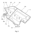
Fig. 3 is a top perspective view of a first part of the housing shown infig. 1 ; -
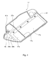
Fig. 4 is a bottom perspective view of a second part of the housing shown infig. 1 . - Referring to the accompanying Figures,
reference numeral 11 generally denotes the housing for an air filter, in a preferred embodiment of the invention intended e.g. for use in the intake system applied to the diesel cycle internal combustion engine of a vehicle. - In this embodiment,
housing 11 includes ahollow shell 13, preferably made of twoparts peripheral edge - Always referring to this exemplary embodiment of the invention,
lower part 15 ofshell 13 is divided by apartition 15c into twozones first zone 15a has an opening 23 intended to be associated with the outlet duct supplying air to the intake manifold of the engine, whilst thesecond zone 15b has anopening 25 intended to be associated with the duct for air intake from the outside. -
Upper part 17 ofshell 13 correspondingly has a pair ofwindows partition 17c, which are superimposed tozones partition 15c oflower part 15 whenshell 13 is assembled. - Shell 13 further includes a
cover 27closing openings - According to the invention,
shell 13 has associated therewith aduct 29 that can advantageously be used also in a circuit other than that of the intake system wherehousing 11 of air filter described herein is included. - More particularly, said
duct 29 can advantageously be used in the circuit for recovering the blow-by gases coming from the base of the internal combustion engine. - Said
duct 29 is preferably equipped, at itsopposite ends fast couplings 35 allowing associating the pipes, generally flexible rubber pipes, of the circuit for recovering the blow-by gases withduct 29. - According to the illustrated embodiment, a
first portion 29a ofduct 29 is formed inlower part 15 ofshell 13, and asecond portion 29b is formed inupper part 17. - Each
portion connector portions edges shell 13. - In the illustrated example, both
portions duct 29 are L-shaped and define a radialfirst section shell 13, and an axialsecond section first section shell 13.Radial sections shell 13 are moreover substantially diametrically opposite. - According to the invention, said
duct 29 is preferably integrated into therespective wall corresponding part shell 13. - Preferably
duct 29, aftershell 13 has been assembled, extends without interruption. Yet,duct 29 could even be interrupted or could have windows or openings on its wall, should said duct be used for instance for the passage of cables or pipes.
Claims (14)
- A housing (11) for an air filter of an internal combustion engine, the housing comprising a shell (13) having an inlet opening (25) and an outlet opening (23) for the inflow of air to be filtered and the outflow of filtered air, respectively, and being characterised in that it further comprises at least one duct (29) associated with said shell (13).
- The housing as claimed in claim 1, wherein at least a portion of said duct (29) is integrated into the wall (43, 45) of said shell (13).
- The housing as claimed in claim 1 or 2, wherein said shell (13) is made of at least two parts (15, 17) of moulded plastics, welded together along the corresponding peripheral edge (19, 21).
- The housing as claimed in claim 3, wherein a first portion (29a) of said duct (29) is formed in a first part (15) of the shell (13), and a second portion (29b) is formed in a second part (17).
- The housing as claimed in claim 4, wherein each portion (29a, 29b) of said duct (29) is equipped with a corresponding portion of a connector (37a, 37b).
- The housing as claimed in claim 5, wherein said connector is of the male-female kind.
- The housing as claimed in claim 6, wherein said portions (29a, 29b) of the duct (29) are L-shaped and define a radial first section (39a, 39b) coming out from said shell (13), and an axial second section (41a, 41b) substantially perpendicular to the first section.
- The housing as claimed in claim 7, wherein said radial sections (39a, 39b) coming out from the shell (13) are substantially diametrically opposite
- The housing as claimed in any preceding claim, wherein said duct (29) extends without interruption.
- The housing as claimed in any preceding claim, wherein said duct (29) is equipped, at its opposite ends (31, 33), with respective fast couplings (35) allowing associating the pipes of the circuit for recovering the blow-by gases of said engine with said duct (29).
- An air filter for an internal combustion engine, characterised in that it comprises a housing as claimed in any of claims 1 to 10.
- A method of manufacturing a housing (11) for an air filter of internal combustion engines, comprising the steps of:- forming a shell (13) having an inlet opening (25) for air to be filtered and an outlet opening (23) for filtered air;- equipping said housing (11) with at least one duct (29) associated with said shell (13).
- The method as claimed in claim 12, wherein said shell (13) is made of plastic material and is formed by the steps of:- moulding a first part (15) and a second part (17) of said shell;- welding said parts (15, 17) together so as to form said shell (13).
- The method as claimed in claim 13, wherein a first portion of said duct is formed on a first part of said shell (13), and a second portion 29b is formed on a second part of said shell (13).
Applications Claiming Priority (1)
| Application Number | Priority Date | Filing Date | Title |
|---|---|---|---|
| ITTO20070493 ITTO20070493A1 (en) | 2007-07-06 | 2007-07-06 | CASE FOR AIR FILTERS OF INTERNAL COMBUSTION ENGINES AND METHOD FOR ITS REALIZATION. |
Publications (3)
| Publication Number | Publication Date |
|---|---|
| EP2011990A2 true EP2011990A2 (en) | 2009-01-07 |
| EP2011990A3 EP2011990A3 (en) | 2009-02-04 |
| EP2011990B1 EP2011990B1 (en) | 2015-07-01 |
Family
ID=39758455
Family Applications (1)
| Application Number | Title | Priority Date | Filing Date |
|---|---|---|---|
| EP08159560.5A Active EP2011990B1 (en) | 2007-07-06 | 2008-07-02 | Housing for air filters of internal combustion engines and method for its production |
Country Status (2)
| Country | Link |
|---|---|
| EP (1) | EP2011990B1 (en) |
| IT (1) | ITTO20070493A1 (en) |
Cited By (1)
| Publication number | Priority date | Publication date | Assignee | Title |
|---|---|---|---|---|
| CN104948357A (en) * | 2015-06-08 | 2015-09-30 | 南京金龙新能源汽车研究院有限公司 | Air filter installation assembly |
Citations (5)
| Publication number | Priority date | Publication date | Assignee | Title |
|---|---|---|---|---|
| FR544415A (en) | 1920-12-14 | 1922-09-22 | Westinghouse Electric & Mfg Co | Improvements to electric motor control systems |
| US4653457A (en) | 1986-03-21 | 1987-03-31 | General Motors Corporation | Air cleaner with crankcase breather assembly |
| EP0447533A1 (en) | 1989-10-02 | 1991-09-25 | Spectra Inc | TREATING IMAGES WITH HOT-MELTABLE INK. |
| EP0741242A1 (en) | 1995-05-05 | 1996-11-06 | Société Anonyme dite: REGIE NATIONALE DES USINES RENAULT | Intake air conduit element for an internal combustion engine |
| US20030226553A1 (en) | 2002-06-07 | 2003-12-11 | Hisakazu Yasui | Engine blowby gas processing system |
Family Cites Families (2)
| Publication number | Priority date | Publication date | Assignee | Title |
|---|---|---|---|---|
| FR1544415A (en) * | 1966-11-17 | 1968-10-31 | Gen Motors Ltd | Air filter for internal combustion engine |
| JP4213968B2 (en) * | 2003-02-14 | 2009-01-28 | 愛知機械工業株式会社 | Blowby gas recirculation device for internal combustion engine |
-
2007
- 2007-07-06 IT ITTO20070493 patent/ITTO20070493A1/en unknown
-
2008
- 2008-07-02 EP EP08159560.5A patent/EP2011990B1/en active Active
Patent Citations (5)
| Publication number | Priority date | Publication date | Assignee | Title |
|---|---|---|---|---|
| FR544415A (en) | 1920-12-14 | 1922-09-22 | Westinghouse Electric & Mfg Co | Improvements to electric motor control systems |
| US4653457A (en) | 1986-03-21 | 1987-03-31 | General Motors Corporation | Air cleaner with crankcase breather assembly |
| EP0447533A1 (en) | 1989-10-02 | 1991-09-25 | Spectra Inc | TREATING IMAGES WITH HOT-MELTABLE INK. |
| EP0741242A1 (en) | 1995-05-05 | 1996-11-06 | Société Anonyme dite: REGIE NATIONALE DES USINES RENAULT | Intake air conduit element for an internal combustion engine |
| US20030226553A1 (en) | 2002-06-07 | 2003-12-11 | Hisakazu Yasui | Engine blowby gas processing system |
Cited By (1)
| Publication number | Priority date | Publication date | Assignee | Title |
|---|---|---|---|---|
| CN104948357A (en) * | 2015-06-08 | 2015-09-30 | 南京金龙新能源汽车研究院有限公司 | Air filter installation assembly |
Also Published As
| Publication number | Publication date |
|---|---|
| EP2011990A3 (en) | 2009-02-04 |
| EP2011990B1 (en) | 2015-07-01 |
| ITTO20070493A1 (en) | 2009-01-07 |
Similar Documents
| Publication | Publication Date | Title |
|---|---|---|
| US7927393B2 (en) | Air cleaner element | |
| CN108472563B (en) | Filter elements and filter systems | |
| JP6203276B2 (en) | Filter cartridge with associated means for draining water and associated filters | |
| EP3647581A1 (en) | Multiple inlet vehicle air filtration system | |
| CN104981281B (en) | Filtration devices, especially air filters | |
| US10105630B2 (en) | Hollow filter element of a filter for filtering fluid, filter, filter housing, and seal of a hollow filter element | |
| CN109641165B (en) | Filter element locking mechanism for cleaning services | |
| CN105899271A (en) | Replaceable filter of a filter device, and filter device | |
| US10105629B2 (en) | Filter, hollow filter element, and filter housing of a filter, and seal of a hollow filter element | |
| WO2016167958A1 (en) | Detachable and reversible pre-cleaner for filter assembly | |
| EP3647580B1 (en) | Multiple inlet filtration system | |
| CN107398113A (en) | Filter for installation | |
| US11660561B2 (en) | Filter element with endcap having rigid reinforcing member | |
| CN207864271U (en) | Filter assemblies and the pump group part being used together with filter assemblies | |
| JP2004538133A5 (en) | ||
| US20070221585A1 (en) | Collapsible Protective Cover for a Filter | |
| EP3211189A1 (en) | Connection structure of blow-by gas hose | |
| EP2011990A2 (en) | Housing for air filters of internal combustion engines and method for its production | |
| KR20060088847A (en) | Filtration system and method with bypass valve flow control | |
| CN204709873U (en) | Liquid separator and the filter element for this liquid separator | |
| US20170067427A1 (en) | Serviceable diesel fuel filter assembly | |
| CN105032003A (en) | Fluid filter and method for producing fluid filter | |
| CN101850198A (en) | Fluid filtering part of engine, filtering shell and fuel-water filter/separator | |
| WO2017015319A1 (en) | Modular transmission side cover assembly | |
| KR20200096665A (en) | Intake filter device with air separation |
Legal Events
| Date | Code | Title | Description |
|---|---|---|---|
| PUAI | Public reference made under article 153(3) epc to a published international application that has entered the european phase |
Free format text: ORIGINAL CODE: 0009012 |
|
| PUAL | Search report despatched |
Free format text: ORIGINAL CODE: 0009013 |
|
| AK | Designated contracting states |
Kind code of ref document: A2 Designated state(s): AT BE BG CH CY CZ DE DK EE ES FI FR GB GR HR HU IE IS IT LI LT LU LV MC MT NL NO PL PT RO SE SI SK TR |
|
| AX | Request for extension of the european patent |
Extension state: AL BA MK RS |
|
| AK | Designated contracting states |
Kind code of ref document: A3 Designated state(s): AT BE BG CH CY CZ DE DK EE ES FI FR GB GR HR HU IE IS IT LI LT LU LV MC MT NL NO PL PT RO SE SI SK TR |
|
| AX | Request for extension of the european patent |
Extension state: AL BA MK RS |
|
| 17P | Request for examination filed |
Effective date: 20090803 |
|
| AKX | Designation fees paid |
Designated state(s): AT BE BG CH CY CZ DE DK EE ES FI FR GB GR HR HU IE IS IT LI LT LU LV MC MT NL NO PL PT RO SE SI SK TR |
|
| 17Q | First examination report despatched |
Effective date: 20120302 |
|
| GRAP | Despatch of communication of intention to grant a patent |
Free format text: ORIGINAL CODE: EPIDOSNIGR1 |
|
| INTG | Intention to grant announced |
Effective date: 20150119 |
|
| GRAS | Grant fee paid |
Free format text: ORIGINAL CODE: EPIDOSNIGR3 |
|
| GRAA | (expected) grant |
Free format text: ORIGINAL CODE: 0009210 |
|
| AK | Designated contracting states |
Kind code of ref document: B1 Designated state(s): AT BE BG CH CY CZ DE DK EE ES FI FR GB GR HR HU IE IS IT LI LT LU LV MC MT NL NO PL PT RO SE SI SK TR |
|
| REG | Reference to a national code |
Ref country code: GB Ref legal event code: FG4D |
|
| REG | Reference to a national code |
Ref country code: AT Ref legal event code: REF Ref document number: 734103 Country of ref document: AT Kind code of ref document: T Effective date: 20150715 Ref country code: CH Ref legal event code: EP |
|
| REG | Reference to a national code |
Ref country code: FR Ref legal event code: PLFP Year of fee payment: 8 |
|
| REG | Reference to a national code |
Ref country code: DE Ref legal event code: R096 Ref document number: 602008038756 Country of ref document: DE |
|
| REG | Reference to a national code |
Ref country code: IE Ref legal event code: FG4D |
|
| REG | Reference to a national code |
Ref country code: AT Ref legal event code: MK05 Ref document number: 734103 Country of ref document: AT Kind code of ref document: T Effective date: 20150701 |
|
| REG | Reference to a national code |
Ref country code: NL Ref legal event code: MP Effective date: 20150701 |
|
| REG | Reference to a national code |
Ref country code: LT Ref legal event code: MG4D |
|
| PG25 | Lapsed in a contracting state [announced via postgrant information from national office to epo] |
Ref country code: GR Free format text: LAPSE BECAUSE OF FAILURE TO SUBMIT A TRANSLATION OF THE DESCRIPTION OR TO PAY THE FEE WITHIN THE PRESCRIBED TIME-LIMIT Effective date: 20151002 Ref country code: LT Free format text: LAPSE BECAUSE OF FAILURE TO SUBMIT A TRANSLATION OF THE DESCRIPTION OR TO PAY THE FEE WITHIN THE PRESCRIBED TIME-LIMIT Effective date: 20150701 Ref country code: FI Free format text: LAPSE BECAUSE OF FAILURE TO SUBMIT A TRANSLATION OF THE DESCRIPTION OR TO PAY THE FEE WITHIN THE PRESCRIBED TIME-LIMIT Effective date: 20150701 Ref country code: LV Free format text: LAPSE BECAUSE OF FAILURE TO SUBMIT A TRANSLATION OF THE DESCRIPTION OR TO PAY THE FEE WITHIN THE PRESCRIBED TIME-LIMIT Effective date: 20150701 Ref country code: NO Free format text: LAPSE BECAUSE OF FAILURE TO SUBMIT A TRANSLATION OF THE DESCRIPTION OR TO PAY THE FEE WITHIN THE PRESCRIBED TIME-LIMIT Effective date: 20151001 |
|
| PG25 | Lapsed in a contracting state [announced via postgrant information from national office to epo] |
Ref country code: ES Free format text: LAPSE BECAUSE OF FAILURE TO SUBMIT A TRANSLATION OF THE DESCRIPTION OR TO PAY THE FEE WITHIN THE PRESCRIBED TIME-LIMIT Effective date: 20150701 Ref country code: PT Free format text: LAPSE BECAUSE OF FAILURE TO SUBMIT A TRANSLATION OF THE DESCRIPTION OR TO PAY THE FEE WITHIN THE PRESCRIBED TIME-LIMIT Effective date: 20151102 Ref country code: IS Free format text: LAPSE BECAUSE OF FAILURE TO SUBMIT A TRANSLATION OF THE DESCRIPTION OR TO PAY THE FEE WITHIN THE PRESCRIBED TIME-LIMIT Effective date: 20151101 Ref country code: PL Free format text: LAPSE BECAUSE OF FAILURE TO SUBMIT A TRANSLATION OF THE DESCRIPTION OR TO PAY THE FEE WITHIN THE PRESCRIBED TIME-LIMIT Effective date: 20150701 Ref country code: HR Free format text: LAPSE BECAUSE OF FAILURE TO SUBMIT A TRANSLATION OF THE DESCRIPTION OR TO PAY THE FEE WITHIN THE PRESCRIBED TIME-LIMIT Effective date: 20150701 Ref country code: SE Free format text: LAPSE BECAUSE OF FAILURE TO SUBMIT A TRANSLATION OF THE DESCRIPTION OR TO PAY THE FEE WITHIN THE PRESCRIBED TIME-LIMIT Effective date: 20150701 Ref country code: AT Free format text: LAPSE BECAUSE OF FAILURE TO SUBMIT A TRANSLATION OF THE DESCRIPTION OR TO PAY THE FEE WITHIN THE PRESCRIBED TIME-LIMIT Effective date: 20150701 |
|
| REG | Reference to a national code |
Ref country code: CH Ref legal event code: PL |
|
| PG25 | Lapsed in a contracting state [announced via postgrant information from national office to epo] |
Ref country code: MC Free format text: LAPSE BECAUSE OF FAILURE TO SUBMIT A TRANSLATION OF THE DESCRIPTION OR TO PAY THE FEE WITHIN THE PRESCRIBED TIME-LIMIT Effective date: 20150701 |
|
| REG | Reference to a national code |
Ref country code: DE Ref legal event code: R097 Ref document number: 602008038756 Country of ref document: DE |
|
| REG | Reference to a national code |
Ref country code: IE Ref legal event code: MM4A |
|
| PG25 | Lapsed in a contracting state [announced via postgrant information from national office to epo] |
Ref country code: EE Free format text: LAPSE BECAUSE OF FAILURE TO SUBMIT A TRANSLATION OF THE DESCRIPTION OR TO PAY THE FEE WITHIN THE PRESCRIBED TIME-LIMIT Effective date: 20150701 Ref country code: LI Free format text: LAPSE BECAUSE OF NON-PAYMENT OF DUE FEES Effective date: 20150731 Ref country code: CH Free format text: LAPSE BECAUSE OF NON-PAYMENT OF DUE FEES Effective date: 20150731 Ref country code: DK Free format text: LAPSE BECAUSE OF FAILURE TO SUBMIT A TRANSLATION OF THE DESCRIPTION OR TO PAY THE FEE WITHIN THE PRESCRIBED TIME-LIMIT Effective date: 20150701 Ref country code: CZ Free format text: LAPSE BECAUSE OF FAILURE TO SUBMIT A TRANSLATION OF THE DESCRIPTION OR TO PAY THE FEE WITHIN THE PRESCRIBED TIME-LIMIT Effective date: 20150701 Ref country code: SK Free format text: LAPSE BECAUSE OF FAILURE TO SUBMIT A TRANSLATION OF THE DESCRIPTION OR TO PAY THE FEE WITHIN THE PRESCRIBED TIME-LIMIT Effective date: 20150701 |
|
| PLBE | No opposition filed within time limit |
Free format text: ORIGINAL CODE: 0009261 |
|
| STAA | Information on the status of an ep patent application or granted ep patent |
Free format text: STATUS: NO OPPOSITION FILED WITHIN TIME LIMIT |
|
| PG25 | Lapsed in a contracting state [announced via postgrant information from national office to epo] |
Ref country code: RO Free format text: LAPSE BECAUSE OF FAILURE TO SUBMIT A TRANSLATION OF THE DESCRIPTION OR TO PAY THE FEE WITHIN THE PRESCRIBED TIME-LIMIT Effective date: 20150701 |
|
| 26N | No opposition filed |
Effective date: 20160404 |
|
| GBPC | Gb: european patent ceased through non-payment of renewal fee |
Effective date: 20151001 |
|
| REG | Reference to a national code |
Ref country code: FR Ref legal event code: PLFP Year of fee payment: 9 |
|
| PG25 | Lapsed in a contracting state [announced via postgrant information from national office to epo] |
Ref country code: IE Free format text: LAPSE BECAUSE OF NON-PAYMENT OF DUE FEES Effective date: 20150702 Ref country code: GB Free format text: LAPSE BECAUSE OF NON-PAYMENT OF DUE FEES Effective date: 20151001 |
|
| PG25 | Lapsed in a contracting state [announced via postgrant information from national office to epo] |
Ref country code: SI Free format text: LAPSE BECAUSE OF FAILURE TO SUBMIT A TRANSLATION OF THE DESCRIPTION OR TO PAY THE FEE WITHIN THE PRESCRIBED TIME-LIMIT Effective date: 20150701 |
|
| PG25 | Lapsed in a contracting state [announced via postgrant information from national office to epo] |
Ref country code: BE Free format text: LAPSE BECAUSE OF FAILURE TO SUBMIT A TRANSLATION OF THE DESCRIPTION OR TO PAY THE FEE WITHIN THE PRESCRIBED TIME-LIMIT Effective date: 20150701 |
|
| PG25 | Lapsed in a contracting state [announced via postgrant information from national office to epo] |
Ref country code: MT Free format text: LAPSE BECAUSE OF FAILURE TO SUBMIT A TRANSLATION OF THE DESCRIPTION OR TO PAY THE FEE WITHIN THE PRESCRIBED TIME-LIMIT Effective date: 20150701 |
|
| PG25 | Lapsed in a contracting state [announced via postgrant information from national office to epo] |
Ref country code: HU Free format text: LAPSE BECAUSE OF FAILURE TO SUBMIT A TRANSLATION OF THE DESCRIPTION OR TO PAY THE FEE WITHIN THE PRESCRIBED TIME-LIMIT; INVALID AB INITIO Effective date: 20080702 Ref country code: BG Free format text: LAPSE BECAUSE OF FAILURE TO SUBMIT A TRANSLATION OF THE DESCRIPTION OR TO PAY THE FEE WITHIN THE PRESCRIBED TIME-LIMIT Effective date: 20150701 |
|
| PG25 | Lapsed in a contracting state [announced via postgrant information from national office to epo] |
Ref country code: NL Free format text: LAPSE BECAUSE OF FAILURE TO SUBMIT A TRANSLATION OF THE DESCRIPTION OR TO PAY THE FEE WITHIN THE PRESCRIBED TIME-LIMIT Effective date: 20150701 Ref country code: CY Free format text: LAPSE BECAUSE OF FAILURE TO SUBMIT A TRANSLATION OF THE DESCRIPTION OR TO PAY THE FEE WITHIN THE PRESCRIBED TIME-LIMIT Effective date: 20150701 |
|
| REG | Reference to a national code |
Ref country code: FR Ref legal event code: PLFP Year of fee payment: 10 |
|
| PG25 | Lapsed in a contracting state [announced via postgrant information from national office to epo] |
Ref country code: LU Free format text: LAPSE BECAUSE OF NON-PAYMENT OF DUE FEES Effective date: 20150702 |
|
| REG | Reference to a national code |
Ref country code: FR Ref legal event code: PLFP Year of fee payment: 11 |
|
| PGFP | Annual fee paid to national office [announced via postgrant information from national office to epo] |
Ref country code: DE Payment date: 20250723 Year of fee payment: 18 |
|
| PGFP | Annual fee paid to national office [announced via postgrant information from national office to epo] |
Ref country code: TR Payment date: 20250702 Year of fee payment: 18 Ref country code: IT Payment date: 20250718 Year of fee payment: 18 |
|
| PGFP | Annual fee paid to national office [announced via postgrant information from national office to epo] |
Ref country code: FR Payment date: 20250725 Year of fee payment: 18 |