EP2011920A1 - Speed controlled eccentric assembly - Google Patents
Speed controlled eccentric assembly Download PDFInfo
- Publication number
- EP2011920A1 EP2011920A1 EP08015166A EP08015166A EP2011920A1 EP 2011920 A1 EP2011920 A1 EP 2011920A1 EP 08015166 A EP08015166 A EP 08015166A EP 08015166 A EP08015166 A EP 08015166A EP 2011920 A1 EP2011920 A1 EP 2011920A1
- Authority
- EP
- European Patent Office
- Prior art keywords
- counterweight
- eccentric
- axis
- fastener
- tubular section
- Prior art date
- Legal status (The legal status is an assumption and is not a legal conclusion. Google has not performed a legal analysis and makes no representation as to the accuracy of the status listed.)
- Granted
Links
- 230000005484 gravity Effects 0.000 claims description 20
- 238000005461 lubrication Methods 0.000 claims description 2
- 239000000463 material Substances 0.000 claims description 2
- 230000000694 effects Effects 0.000 description 4
- 230000003247 decreasing effect Effects 0.000 description 3
- 239000012530 fluid Substances 0.000 description 3
- 230000006835 compression Effects 0.000 description 2
- 238000007906 compression Methods 0.000 description 2
- 238000007789 sealing Methods 0.000 description 2
- 230000000712 assembly Effects 0.000 description 1
- 238000000429 assembly Methods 0.000 description 1
- 230000007423 decrease Effects 0.000 description 1
- 239000013536 elastomeric material Substances 0.000 description 1
- 238000009434 installation Methods 0.000 description 1
- 239000000314 lubricant Substances 0.000 description 1
- 230000001681 protective effect Effects 0.000 description 1
- 230000003068 static effect Effects 0.000 description 1
- 238000003466 welding Methods 0.000 description 1
Images




Classifications
-
- E—FIXED CONSTRUCTIONS
- E01—CONSTRUCTION OF ROADS, RAILWAYS, OR BRIDGES
- E01C—CONSTRUCTION OF, OR SURFACES FOR, ROADS, SPORTS GROUNDS, OR THE LIKE; MACHINES OR AUXILIARY TOOLS FOR CONSTRUCTION OR REPAIR
- E01C19/00—Machines, tools or auxiliary devices for preparing or distributing paving materials, for working the placed materials, or for forming, consolidating, or finishing the paving
- E01C19/22—Machines, tools or auxiliary devices for preparing or distributing paving materials, for working the placed materials, or for forming, consolidating, or finishing the paving for consolidating or finishing laid-down unset materials
- E01C19/23—Rollers therefor; Such rollers usable also for compacting soil
- E01C19/28—Vibrated rollers or rollers subjected to impacts, e.g. hammering blows
- E01C19/286—Vibration or impact-imparting means; Arrangement, mounting or adjustment thereof; Construction or mounting of the rolling elements, transmission or drive thereto, e.g. to vibrator mounted inside the roll
-
- B—PERFORMING OPERATIONS; TRANSPORTING
- B06—GENERATING OR TRANSMITTING MECHANICAL VIBRATIONS IN GENERAL
- B06B—METHODS OR APPARATUS FOR GENERATING OR TRANSMITTING MECHANICAL VIBRATIONS OF INFRASONIC, SONIC, OR ULTRASONIC FREQUENCY, e.g. FOR PERFORMING MECHANICAL WORK IN GENERAL
- B06B1/00—Methods or apparatus for generating mechanical vibrations of infrasonic, sonic, or ultrasonic frequency
- B06B1/10—Methods or apparatus for generating mechanical vibrations of infrasonic, sonic, or ultrasonic frequency making use of mechanical energy
- B06B1/16—Methods or apparatus for generating mechanical vibrations of infrasonic, sonic, or ultrasonic frequency making use of mechanical energy operating with systems involving rotary unbalanced masses
- B06B1/161—Adjustable systems, i.e. where amplitude or direction of frequency of vibration can be varied
- B06B1/162—Making use of masses with adjustable amount of eccentricity
- B06B1/164—Making use of masses with adjustable amount of eccentricity the amount of eccentricity being automatically variable as a function of the running condition, e.g. speed, direction
Definitions
- This invention relates to vibration compacting machines, and more particularly to an eccentric assembly for a vibration compacting machine.
- an eccentric assembly for a vibration compacting machine, the eccentric assembly comprising a substantially closed tubular section having at least one sealable through bore and being rotatable about an axis; an eccentric weight coupled within the tubular section and having a centre of gravity on a first side of the axis; a counterweight coupled within the tubular section and having a centre of gravity on a second, opposite side of the axis, the counterweight being moveable relative to the eccentric weight over a range between a first position and a second position; a fastener extending from the eccentric weight, through the counterweight and including a head member that is aligned with the through bore; a biasing member positioned about the fastener between the fastener head and the counterweight such that a biasing force biases the counterweight toward the first position, adjustment of the fastener through the through bore permitting adjustment of the biasing force; and a cap for sealingly closing the through bore.
- the eccentric assembly can generate vibrations that have a lower amplitude at high rotational speeds (i.e. frequencies). Reducing vibration amplitude at higher shaft speeds minimises wear to each of the load bearing components in the vibration compacting machine, resulting in an extended service life for the vibration compacting machine.
- the present eccentric assembly is easily and inexpensively manufactured, can be readily adapted to be used in existing vibration compacting machines and encases all critical moving components within a protective tubular section.
- the eccentric assembly includes a tubular section, an eccentric weight, and a counterweight.
- Fig. 1 illustrates a vibration compacting machine used in leveling paved or unpaved ground surfaces.
- the vibration compacting machine 8 includes a frame 12 and at least one drum assembly 14 mounted to one end of the frame 12 for rotation about a longitudinal axis 13.
- the opposite end of the frame 12 generally has a wheel assembly 11 or a second drum assembly (not shown) that, with drum assembly 14, supports the frame 12 for movement over the ground surface.
- An operator's station 9, including a steering wheel 10 or the like, is provided on the frame 12 for driving and operation of the compacting machine 8.
- the drum assembly 14 includes a drum 16 and an eccentric assembly 20 that is mounted for rotation relative to the drum 16.
- the eccentric assembly 20 rotates about an axis of rotation 21 that is substantially aligned with the longitudinal axis 13 of the drum assembly 14.
- the eccentric assembly 20 includes a moment of eccentricity such that rotation of the eccentric assembly 20 by a motor 15 creates vibrations that are transferred through the drum 16 to the ground.
- the biasing members 60 are preferably compression springs, but other structures, for example, an elastomeric material or a semi-compressible fluid, may also be used. In the case of a fluid, the shoulder members 54 would provide a sealing fit to prevent leakage of such fluid.
- the eccentric weight 30 and counterweight 40 structure can easily be changed by detaching the eccentric weight 30 from the tubular section 24, for example, by removing securing screws, and securing a different eccentric weight 30 and counterweight 40 structure within the tubular section 24.
- Each fastener 50 has a head portion 52 which overlies a portion of the shoulder member 54 such that tightening of the fastener 50 compresses the biasing member 40 within the receiving portion 47 of the bore 46.
- the counterweight 40 is thereby biased toward a first position ( Fig. 5 ) wherein the counterweight first portion 42 is received fully in the eccentric weight cavity 34. Tightening or loosening of the fastener 50 controls the compression, and corresponding biasing force, of the biasing member 60.
- the counterweight 40 is moveable over a range between the first position ( Fig. 5 ) and a second position ( Fig. 6 ) wherein the convex surface 45 of the counterweight 40 is in contact with the inner surface 25 of the tubular section 24.
Landscapes
- Engineering & Computer Science (AREA)
- Mechanical Engineering (AREA)
- Architecture (AREA)
- Civil Engineering (AREA)
- Structural Engineering (AREA)
- Apparatuses For Generation Of Mechanical Vibrations (AREA)
- Road Paving Machines (AREA)
Abstract
Description
- This invention relates to vibration compacting machines, and more particularly to an eccentric assembly for a vibration compacting machine.
- Vibration compacting machines are used in levelling paved or unpaved ground surfaces. A typical vibration compacting machine includes an eccentric assembly for generating vibrations that are transferred to a drum assembly of the compacting machine. The eccentric assembly commonly includes one or more eccentric weights that are adjustable between a plurality of discrete radial positions relative to a shaft in order to vary the amplitude of the vibrations that are generated by rotating the eccentric weight(s) about the shaft.
- One such device includes a plurality of eccentric weights that are fixed to the shaft and a corresponding number of counterweights that are coupled to the opposite side of the shaft relative to the eccentric weights. The counterweights are moveable between a retracted position and a projected position relative to the longitudinal axis of the shaft. When the counterweights are in the retracted position their effect on the eccentric weights is minimised, resulting in maximum vibration amplitude being generated by the eccentric weights. The counterweights are normally biased toward the retracted position, however as the shaft rotates the biasing force is overcome and the counterweights are moved to the projected position where the counterweights are further away from the shaft. As the counterweights move further from the shaft, the counterweights reduce the effect of the eccentric weights resulting in a lower vibration amplitude. Examples of eccentric weight assemblies are shown in
US-A-4 341 126 ,US-A-3 867 073 andDE 100 31 617 A . - One type of adjustable eccentric assembly operates by varying the rotational speed of the shaft. The eccentric assembly includes one or more eccentric weights that are biased toward the shaft. During operation of the eccentric assembly the shaft rotates, and as the rotational speed of the shaft increases, a centrifugal force overcomes the biasing force and causes the eccentric weight to move away from the shaft. The vibration amplitude increases as the eccentric weights move away from the shaft.
According to one aspect of the present invention, there is provided an eccentric assembly for a vibration compacting machine, the eccentric assembly comprising a substantially closed tubular section having at least one sealable through bore and being rotatable about an axis; an eccentric weight coupled within the tubular section and having a centre of gravity on a first side of the axis; a counterweight coupled within the tubular section and having a centre of gravity on a second, opposite side of the axis, the counterweight being moveable relative to the eccentric weight over a range between a first position and a second position; a fastener extending from the eccentric weight, through the counterweight and including a head member that is aligned with the through bore; a biasing member positioned about the fastener between the fastener head and the counterweight such that a biasing force biases the counterweight toward the first position, adjustment of the fastener through the through bore permitting adjustment of the biasing force; and a cap for sealingly closing the through bore.
According to another aspect of the present invention, there is provided an eccentric assembly for a vibration compacting machine, the eccentric assembly comprising a substantially closed tubular section rotatable about an axis; an eccentric weight coupled within the tubular section and having a centre of gravity on a first side of the axis; a counterweight coupled within the tubular section and having a bore of a given diameter, the counterweight having a centre of gravity on a second, opposite side of the axis, the counterweight being moveable relative to the eccentric weight over a range between a first position and a second position; a fastener extending from the eccentric weight through the counterweight and including a head member having a shoulder portion having a diameter substantially the same as the given diameter; a biasing member positioned in the bore about the fastener between the fastener head member and the counterweight, the fastener being tightened such that the shoulder is within the bore substantially to enclose the biasing member therein, the biasing member generating a biasing force that biases the counterweight toward the first position.
Rotating the eccentric assembly generates vibrations that can be transferred to the drum assembly of a vibration compacting machine.
The eccentric assembly can generate vibrations that have a lower amplitude at high rotational speeds (i.e. frequencies). Reducing vibration amplitude at higher shaft speeds minimises wear to each of the load bearing components in the vibration compacting machine, resulting in an extended service life for the vibration compacting machine. The present eccentric assembly is easily and inexpensively manufactured, can be readily adapted to be used in existing vibration compacting machines and encases all critical moving components within a protective tubular section.
The eccentric assembly includes a tubular section, an eccentric weight, and a counterweight. The eccentric weight is mounted within the tubular section such that as a motor rotates the eccentric assembly, the eccentric weight generates vibrations that are transferred to the drum assembly of the vibration compacting machime. The eccentric assembly also includes a counterweight that is slidably coupled to the eccentric weight. The counterweight moves over a range between a first position where the counterweight contacts the eccentric weight and a second position where the counterweight contacts the tubular section.
During operation of the vibration compacting machine, the eccentric assembly generates a maximum moment of eccentricity about an axis of rotation when the counterweight is in contact with the eccentric weight(i.e. the first position). As the rotational speed of the eccentric assembly increases, the eccentric weight and the counterweight are separated and the moment of eccentricity generated by the rotating eccentric assembly decreases.
The counterweight is preferably biased toward the first position by a spring. The counterweight will remain in the first position until the eccentric assembly is rotated at a sufficient speed to create a centrifugal force on the counterweight that overcomes the biasing force generated by the spring. Once the centrifugal force is larger than the biasing force, the counterweight moves toward the second position, thereby lowering the moment of eccentricity and decreasing the vibration amplitude.
For a better understanding of the invention and to show how the same may be carried into effect, reference will now be made, by way of example, to the accompanying drawings, in which:- -
Fig. 1 is an isometric view of a vibration compacting machine including an eccentric assembly, -
Fig. 2 is a section view of a drum assembly of the vibration compacting machine illustrated inFig. 1 taken along line 2-2, -
Fig. 3 is an isometric view of an eccentric assembly, -
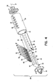
Fig. 4 is an exploded isometric view of the eccentric assembly illustrated inFig. 3 , -
Fig. 5 is a section view taken along line 5-5 inFig. 2 , illustrating the eccentric assembly in a static condition, -
Fig. 6 is a section view similar toFig. 5 , illustrating the eccentric assembly in a dynamic condition, and -
Fig. 7 is a section view taken along line 7-7 inFig. 5 . -
Fig. 1 illustrates a vibration compacting machine used in leveling paved or unpaved ground surfaces. Thevibration compacting machine 8 includes aframe 12 and at least onedrum assembly 14 mounted to one end of theframe 12 for rotation about alongitudinal axis 13. The opposite end of theframe 12 generally has awheel assembly 11 or a second drum assembly (not shown) that, withdrum assembly 14, supports theframe 12 for movement over the ground surface. An operator's station 9, including asteering wheel 10 or the like, is provided on theframe 12 for driving and operation of thecompacting machine 8. These features of thevibration compacting machine 8 are known in the art. - Referring now also to
Fig. 2 , thedrum assembly 14 includes adrum 16 and aneccentric assembly 20 that is mounted for rotation relative to thedrum 16. Theeccentric assembly 20 rotates about an axis ofrotation 21 that is substantially aligned with thelongitudinal axis 13 of thedrum assembly 14. Theeccentric assembly 20 includes a moment of eccentricity such that rotation of theeccentric assembly 20 by amotor 15 creates vibrations that are transferred through thedrum 16 to the ground. - The preferred
eccentric assembly 20 includes twoflanged journals 22 at the ends of atubular section 24. Theflanged journals 22 are coupled to bearings 17 (shown only inFig. 2 ) at each end of theeccentric assembly 20. Thebearings 17 are secured toparallel supports 19, preferably circular plates, mounted in and extending across the inner diameter of thedrum 16. Thesupports 19 are welded to an interior wall of thedrum 16 and are generally perpendicular to thelongitudinal axis 13 of thedrum 16. Themotor 15 rotates theflanged journals 22 about the axis ofrotation 21 such that theeccentric assembly 20 generates vibrations that are transferred to thedrum 14. - Referring to
Figs. 3-7 , thetubular section 24 is mounted at each end to theflanged journals 22 using fasteners that are configured in a circular bolt pattern. Thetubular section 24 is mounted to theflanged journals 22 such that the central axis of thetubular section 24 is substantially aligned with the axis ofrotation 21 of theeccentric assembly 20. Thetubular section 24 is preferably cylindrically shaped and contains cylindrical or concaveinner surface 25 that extends along its length. As best seen inFig. 4 , a plurality of fastener securingbores 26, withcorresponding caps 28, the function of which will be described hereinafter, are provided through thetubular section 24 on one side of theaxis 21. Thetubular section 24 is independently mountable and rotatable irrespective of the configuration of theeccentric weight 30 orcounterweight 40. - Referring now particularly to
Figs. 4-7 ,eccentric assembly 20 also includes aneccentric weight 30, acounterweight 40, a plurality offasteners 50 and a plurality of biasingmembers 60. Theeccentric weight 30 is fixed within thetubular section 24 such that a centre of gravity Ⓔ of theeccentric weight 30 is located on a first side of the axis of rotation 21 (below theaxis 21 inFigs. 5-7 ). The first side of the axis ofrotation 21 is preferably opposite the side of the axis ofrotation 21 along which the fastener securingbores 26 are provided (hereinafter referred to as the second side of theaxis 21, which is above theaxis 21 inFigs. 5-7 ). Theeccentric weight 30 is preferably semi-cylindrical and extends along a substantial length of thetubular section 24. Theeccentric weight 30 includes a generally planarfirst surface 32 and a convex or semi-cylindricalouter surface 33. Theeccentric weight 30 is fixed within thetubular section 24 such that thefirst surface 32 is along or on the first side of the axis ofrotation 21. In other words, as seen inFigs. 5 and 6 , thesurface 32 defines a chord of thetubular section 24. Theeccentric weight 30 may be permanently fixed, for example, via welding, or may be releasably secured, for example, via screws (not shown), to allow easy interchanging thereof. - The
convex surface 33 is similar in curvature to theinner surface 25 of thetubular section 24 such that substantially theentire surface 33 is positioned against substantially theentire surface 25. Thefirst surface 32 of theweight 30 preferably has arectangular cavity 34 extending along its length. Thecavity 34 is configured to receive a portion of thecounterweight 40 as will be described hereinafter. As best seen inFig. 4 , a plurality of fastener receiving bores 36 are provided along the bottom surface of thecavity 34. - The
counterweight 40 has a center of gravityⓉand first andsecond portions first portion 42 is configured to be received within theeccentric weight cavity 34 and has a center of gravity① which is on the first side of (below) theaxis 21 when thefirst portion 42 is received fully in the cavity 34 (Fig. 5 ). Thesecond portion 44 has a second portion center ofgravity ② and is configured such that the centers of gravityⓉ and ② are both located on the second side of (above) the axis ofrotation 21 at all times. Thesecond portion 44 of thecounterweight 40 also includes aconvex surface 45 that extends along the entire length of thecounterweight 40 and substantially defines a semi-cylindrical shape that is similar in curvature to theinner surface 25 of thetubular section 24. - The
counterweight 40 is slidably coupled to theeccentric weight 30 by at least onefastener 50 extending through abore 46 in thecounterweight 40. As shown inFigs. 4-7 , a plurality ofbores 46 are preferably provided, each bore 46 having a large-diameter receiving section 47 and a small-diameter throughsection 48. The receivingsection 47 is configured to receive and maintain one of the biasingmembers 60 positioned therein. Ashoulder member 54 or washer is positioned over the biasingmember 60 adjacent the open end of thebore 46. Theshoulder member 54 is preferably sized to substantially close the open end of thebore 46 to reduce passage of lubricants or debris that may be present in thetubular section 24. Since material will generally move to theeccentric weight 30 side of thetubular section 24 when theassembly 20 is at rest and to the tubular sectioninternal surface 25 when theassembly 20 is rotating, a sealing fit is generally not required of theshoulder member 54, but such may be provided. The biasingmembers 60 are preferably compression springs, but other structures, for example, an elastomeric material or a semi-compressible fluid, may also be used. In the case of a fluid, theshoulder members 54 would provide a sealing fit to prevent leakage of such fluid. - To couple the
counterweight 40 to theeccentric weight 30, afastener 50, preferably a threaded bolt, is inserted through theshoulder member 54, the biasingmember 60 and the throughsection 48 and secured in a corresponding eccentric weight threaded bore 36. While threaded bolts and corresponding threaded bores are preferred, other types of fastening arrangements, for example, a ratchet fit rod and catch, may also be used. Since thecounterweight 40 is coupled to theeccentric weight 30 as an independent structure and thetubular section 24 is independent of such structure, theeccentric weight 30 andcounterweight 40 structure can easily be changed by detaching theeccentric weight 30 from thetubular section 24, for example, by removing securing screws, and securing a differenteccentric weight 30 andcounterweight 40 structure within thetubular section 24. - Each
fastener 50 has ahead portion 52 which overlies a portion of theshoulder member 54 such that tightening of thefastener 50 compresses the biasingmember 40 within the receivingportion 47 of thebore 46. Thecounterweight 40 is thereby biased toward a first position (Fig. 5 ) wherein the counterweightfirst portion 42 is received fully in theeccentric weight cavity 34. Tightening or loosening of thefastener 50 controls the compression, and corresponding biasing force, of the biasingmember 60. Thecounterweight 40 is moveable over a range between the first position (Fig. 5 ) and a second position (Fig. 6 ) wherein theconvex surface 45 of thecounterweight 40 is in contact with theinner surface 25 of thetubular section 24. - It should be noted that the
inner surface 25 of thetubular section 24 and theouter surface 33 of theeccentric weight 30 are preferably is substantially surface contact along their length. Theconvex surface 45 of thecounterweight 40 and theinner surface 25 of thetubular section 24 are also preferably in surface contact when thecounterweight 40 is in the second position. However, point or line contact between any of these surface pairs is possible. Furthermore, it is not required that theeccentric weight 30 and/or thecounterweight 40 be manufactured as one continuous piece. Theeccentric weight 30 and thecounterweight 40 may consist of a plurality of smaller individual weights distributed along the length of thetubular section 24. - During operation of the
eccentric assembly 20, theeccentric weight 30 and thecounterweight 40 are initially in the first position (Fig. 5 ) with the biasingmembers 60 maintaining thefirst portion 42 of thecounterweight 40 received fully within thecavity 34 of theeccentric weight 30. In the first position, the eccentric weight and counterweight first portion centres of gravityⒺ and① are on the first side of (below) theaxis 21 and the counterweight second portion and overall centers of gravity② andⓉ are in their closest position relative to theaxis 21 such that theeccentric assembly 20 has a maximum moment of eccentricity. It will also be seen inFig. 5 that in the first position, the biasingmember 60 extends between both sides of the tubular section and thereby has a center of gravityⓈ proximate the axis ofrotation 21.
As a result, in the first position, the biasingmember 60 has a minimal effect on the moment of eccentricity. - As the
motor 15 begins rotating theflanged journals 22, theeccentric assembly 20 generates vibrations that are transferred to thedrum assembly 14 of thevibration compacting machine 8. Theeccentric assembly 20 operates in either direction of rotation, however, there is a performance advantage when the rotational direction of theeccentric assembly 20 coincides with the rotational direction of thedrum 16. - Rotation of the
eccentric assembly 20 generates a centrifugal force on thecounterweight 40 that urges thecounterweight 40 to move away from the eccentric weight 30 (upward inFigs. 5 and 6 ). When theeccentric assembly 20 is rotated at a sufficient speed, the centrifugal force acting on thecounterweight 40 overcomes the biasing force provided by the biasingmembers 60 such that thecounterweight 40 compresses the biasingmembers 60 and slides along thefasteners 50 away from the first position. As explained above, thefasteners 60 can be tightened or loosened to define the biasing force and thereby the force which must be overcome to begin movement of thecounterweight 40. Such calibration of thefasteners 60 can be performed before installation of theeccentric weight 30 andcounterweight 40 in thetubular section 40. Alternatively, thefasteners 60 can be accessed through the fastener securing bores 26 to perform field calibrations and the like. After calibration is performed through thebores 26, caps 28 are preferably inserted into thebores 26 to sealingly close such and prevent leakage of oil or other lubrication (not shown) preferably contained in thetubular section 24. - As the
counterweight 40 moves away from theeccentric weight 20, thecounterweight 40 both reduces and offsets the maximum moment of eccentricity, i.e. - as the first portion centreof gravity① moves toward theaxis 21, the maximum moment of eccentricity is reduced and as the second portion and overall centers of gravity② andⓉ move further from theaxis 21, the maximum moment of eccentricity is further offset by thecounterweight 40. Additionally, referring toFig. 6 , the biasing member centre of gravityⓈ also moves to the second side of (above) theaxis 21 to also further offset the maximum moment of eccentricity. As the speed of theeccentric assembly 20 continues to increase, thecounterweight 40 eventually moves a maximum distance away from the eccentric weight 30 (Fig. 6 ) where theconvex surface 36 of thecounterweight 40 is in contact with theinner surface 25 of thetubular section 24. - When the
counterweight 40 is the maximum distance from theeccentric weight 30, theeccentric assembly 20 has a minimum moment of eccentricity. A lower moment of eccentricity about the axis ofrotation 21 generates vibrations with lower amplitudes. Therefore, the vibration amplitude generated by theeccentric assembly 20 when thecounterweight 40 is in the second position is smaller than the vibration amplitude that is generated when thecounterweight 40 is in the first position with a complete range of decreasing amplitude as thecounterweight 40 moves from the first to the second position. The lower vibration amplitude at increased vibration frequencies reduces bearing wear and extends bearing life. - Accordingly, an operator can control the eccentric amplitude by increasing or decreasing the eccentric assembly rotational speed as desired.
Claims (7)
- An eccentric assembly (20) for a vibration compacting machine (8), the eccentric assembly (20) comprising:a substantially closed tubular section (24) having at least one sealable through bore (26) and being rotatable about an axis;an eccentric weight (30) coupled within the tubular section (24) and having a centre of gravity on a first side of the axis;a counterweight (40) coupled within the tubular section (24) and having a centre of gravity on a second, opposite side of the axis, the counterweight (40) being moveable relative to the eccentric weight (30) over a range between a first position and a second position;a fastener (50) extending from the eccentric weight (30), through the counterweight (40) and including a head member (52) that is aligned with the through bore (26);a biasing member (60) positioned about the fastener (50) between the fastener head (52) and the counterweight (40) such that a biasing force biases the counterweight (40) toward the first position, adjustment of the fastener (50) through the through bore (26) permitting adjustment of the biasing force; anda cap (28) for sealingly closing the through bore (26).
- An eccentric assembly (20) according to claim 1, wherein the fastener (50) is a threaded bolt.
- An eccentric assembly (20) according to claim 1 or 2, wherein a lubrication material is provided within the tubular section (24).
- An eccentric assembly (20) for a vibration compacting machine (8), the eccentric assembly (20) comprising:a substantially closed tubular section (24) rotatable about an axis;an eccentric weight (30) coupled within the tubular section (24) and having a centre of gravity on a first side of the axis;a counterweight (40) coupled within the tubular section (24) and having a bore (46) of a given diameter, the counterweight (40) having a centre of gravity on a second, opposite side of the axis, the counterweight (40) being moveable relative to the eccentric weight (30) over a range between a first position and a second position;a fastener (50) extending from the eccentric weight (30), through the counterweight (40) and including a head member (52) having a shoulder portion (54) having a diameter substantially the same as the given diameter;a biasing member (60) positioned in the bore (46) about the fastener (50) between the fastener head member (52) and the counterweight (40), the fastener (50) being tightened such that the shoulder (54) is within the bore (46) substantially to enclose the biasing member (60) therein, the biasing member (60) generating a biasing force that biases the counterweight (40) toward the first position.
- An eccentric assembly (20) according to claim 4, wherein the eccentric weight (30) includes a cavity (34) beginning on the first side of the axis and opening toward the second side of the axis and the counterweight (40) has first and second portions (42, 44) with the bore (46) extending into both portions (42, 44), each portion (42, 44) and the biasing member (60) having a centre of gravity, the portions (42, 44) being configured such that in the first position, the first portion (42) extends into the cavity (34) such that the first portion (42) centre of gravity is on the first side of the axis, the second portion (44) centre of gravity is on the second side of the axis and the biasing member (60) centre of gravity is along or on the first side of the axis.
- An eccentric assembly (20) according to claim 4 or 5, wherein the fastener (50) is adjustable and adjustment of the fastener (50) adjusts the biasing force.
- An eccentric assembly (20) according to claim 6, wherein the tubular section includes at least one sealable through bore (26) aligned with the fastener (50) for adjustment thereof.
Applications Claiming Priority (2)
| Application Number | Priority Date | Filing Date | Title |
|---|---|---|---|
| US09/901,840 US6585450B2 (en) | 2001-07-10 | 2001-07-10 | Speed controlled eccentric assembly |
| EP02746961A EP1404923B1 (en) | 2001-07-10 | 2002-07-10 | Speed controlled eccentric assembly |
Related Parent Applications (2)
| Application Number | Title | Priority Date | Filing Date |
|---|---|---|---|
| EP02746961A Division EP1404923B1 (en) | 2001-07-10 | 2002-07-10 | Speed controlled eccentric assembly |
| EP02746961.8 Division | 2002-07-10 |
Publications (2)
| Publication Number | Publication Date |
|---|---|
| EP2011920A1 true EP2011920A1 (en) | 2009-01-07 |
| EP2011920B1 EP2011920B1 (en) | 2010-09-01 |
Family
ID=25414899
Family Applications (2)
| Application Number | Title | Priority Date | Filing Date |
|---|---|---|---|
| EP08015166A Expired - Lifetime EP2011920B1 (en) | 2001-07-10 | 2002-07-10 | Speed controlled eccentric assembly |
| EP02746961A Expired - Lifetime EP1404923B1 (en) | 2001-07-10 | 2002-07-10 | Speed controlled eccentric assembly |
Family Applications After (1)
| Application Number | Title | Priority Date | Filing Date |
|---|---|---|---|
| EP02746961A Expired - Lifetime EP1404923B1 (en) | 2001-07-10 | 2002-07-10 | Speed controlled eccentric assembly |
Country Status (4)
| Country | Link |
|---|---|
| US (1) | US6585450B2 (en) |
| EP (2) | EP2011920B1 (en) |
| DE (2) | DE60237557D1 (en) |
| WO (1) | WO2003006742A1 (en) |
Families Citing this family (11)
| Publication number | Priority date | Publication date | Assignee | Title |
|---|---|---|---|---|
| SE525020C2 (en) * | 2003-03-21 | 2004-11-09 | Metso Dynapac Ab | Actuators for controlling the eccentric torque of a roller-driven eccentric shaft |
| US7066681B2 (en) * | 2004-11-17 | 2006-06-27 | M-B-W Inc. | Shaft assembly for a vibratory roller |
| DE602005003342T2 (en) * | 2005-06-23 | 2008-09-11 | Akg Acoustics Gmbh | Method for modeling a microphone |
| US7588389B1 (en) * | 2006-12-19 | 2009-09-15 | Humphrey John L | Greensroller with variable vibration amplitude |
| US20110017482A1 (en) * | 2009-07-23 | 2011-01-27 | Keith Carl A | Roller Technology |
| US20110158745A1 (en) * | 2009-12-31 | 2011-06-30 | Caterpillar Paving Products Inc. | Vibratory system for a compactor |
| WO2014175787A1 (en) * | 2013-04-25 | 2014-10-30 | Volvo Construction Equipment Ab | Assembly for vibrating a compacting drum of a compacting machine |
| US10166573B2 (en) | 2015-12-28 | 2019-01-01 | Volvo Construction Equipment Ab | Eccentric assembly for a vibration compacting machine |
| US10024004B1 (en) | 2017-02-28 | 2018-07-17 | Caterpillar Paving Products Inc. | Variable eccentricity via sliding mechanism |
| CN108374307B (en) * | 2018-03-16 | 2021-05-11 | 浙江路之友工程机械有限公司 | Impact steel wheel of road roller |
| CN113665226B (en) * | 2021-08-16 | 2022-07-12 | 清远南方制版科技有限公司 | Dynamic balance deviation correcting device and deviation correcting method applying same |
Citations (4)
| Publication number | Priority date | Publication date | Assignee | Title |
|---|---|---|---|---|
| US3867073A (en) | 1972-09-20 | 1975-02-18 | Raygo Inc | Control for fluid motor |
| US4341126A (en) | 1977-02-25 | 1982-07-27 | Thomas Hubert E | Variable amplitude vibratory apparatus |
| US4367054A (en) * | 1981-02-24 | 1983-01-04 | The Koehring Company | Vibratory roller |
| DE10031617A1 (en) | 2000-06-29 | 2002-01-17 | Wacker Werke Kg | Vibration exciter with amplitude adjustment |
Family Cites Families (15)
| Publication number | Priority date | Publication date | Assignee | Title |
|---|---|---|---|---|
| US2481174A (en) | 1949-01-03 | 1949-09-06 | Jeffrey Mfg Co | Variable unbalanced weight mechanism for mechanical vibrating screens and the like |
| US2989869A (en) * | 1957-02-25 | 1961-06-27 | Continental Oil Co | Constant force variable speed vibrator |
| CH465935A (en) | 1967-10-27 | 1968-11-30 | Meyer Fa Rudolf | Vibrator with squirrel cage motor |
| DE2127433B2 (en) * | 1971-06-03 | 1973-05-30 | Grimmer, Klaus Jürgen, Dr Ing , 4720 Beckum | UNBALANCE EXCITER FOR DRIVING A VIBRATING CHANNEL OR VIBRATING SCREEN |
| US3896677A (en) | 1974-01-18 | 1975-07-29 | Raygo Inc | Dual amplitude vibration generator |
| US4033193A (en) | 1974-03-04 | 1977-07-05 | International Combustion Australia Limited | Vibratory drive unit |
| US4176983A (en) | 1978-07-17 | 1979-12-04 | Ingersoll-Rand Company | Variable eccentric device |
| US4342523A (en) | 1981-02-24 | 1982-08-03 | Koehring Company | High-low force amplitude device |
| SE434550B (en) * | 1983-01-26 | 1984-07-30 | Dynapac Maskin Ab | DEVICE FOR STORAGE OF LARGE ECCENTER FORCES |
| US4550622A (en) | 1983-05-12 | 1985-11-05 | Ingersoll-Rand Company | Plural-amplitude vibration assembly |
| US4568218A (en) * | 1984-07-16 | 1986-02-04 | Wacker Corporation | Adjustably controllable centrifugal vibratory exciter |
| US4759659A (en) * | 1987-07-01 | 1988-07-26 | Fernand Copie | Variable vibrator system |
| US4749305A (en) * | 1987-08-31 | 1988-06-07 | Ingersoll-Rand Company | Eccentric-weight subassembly, and in combination with an earth compactor drum |
| US4830534A (en) | 1987-10-21 | 1989-05-16 | Hyster Company | Dual amplitude vibration generator for compaction apparatus |
| DE19529115A1 (en) * | 1995-08-08 | 1997-03-06 | Wacker Werke Kg | Vibration mechanism, particularly for use in soil compaction |
-
2001
- 2001-07-10 US US09/901,840 patent/US6585450B2/en not_active Expired - Lifetime
-
2002
- 2002-07-10 EP EP08015166A patent/EP2011920B1/en not_active Expired - Lifetime
- 2002-07-10 DE DE60237557T patent/DE60237557D1/en not_active Expired - Lifetime
- 2002-07-10 DE DE60231713T patent/DE60231713D1/en not_active Expired - Lifetime
- 2002-07-10 WO PCT/US2002/021815 patent/WO2003006742A1/en not_active Ceased
- 2002-07-10 EP EP02746961A patent/EP1404923B1/en not_active Expired - Lifetime
Patent Citations (4)
| Publication number | Priority date | Publication date | Assignee | Title |
|---|---|---|---|---|
| US3867073A (en) | 1972-09-20 | 1975-02-18 | Raygo Inc | Control for fluid motor |
| US4341126A (en) | 1977-02-25 | 1982-07-27 | Thomas Hubert E | Variable amplitude vibratory apparatus |
| US4367054A (en) * | 1981-02-24 | 1983-01-04 | The Koehring Company | Vibratory roller |
| DE10031617A1 (en) | 2000-06-29 | 2002-01-17 | Wacker Werke Kg | Vibration exciter with amplitude adjustment |
Also Published As
| Publication number | Publication date |
|---|---|
| EP2011920B1 (en) | 2010-09-01 |
| EP1404923A1 (en) | 2004-04-07 |
| DE60237557D1 (en) | 2010-10-14 |
| EP1404923B1 (en) | 2009-03-25 |
| DE60231713D1 (en) | 2009-05-07 |
| US20030012602A1 (en) | 2003-01-16 |
| WO2003006742A1 (en) | 2003-01-23 |
| US6585450B2 (en) | 2003-07-01 |
Similar Documents
| Publication | Publication Date | Title |
|---|---|---|
| EP2011920B1 (en) | Speed controlled eccentric assembly | |
| US4753128A (en) | Robot with spring pivot balancing mechanism | |
| DE3590411C2 (en) | Tensioner for revolving belt in e.g. vehicle engine | |
| CA2133677C (en) | Coupling for rotary-vibratory drills | |
| US9725855B2 (en) | Assembly for vibrating a compacting drum of a compacting machine | |
| RU2304241C2 (en) | Stretching apparatus of mechanical belt transmission, mechanical drive, and method for stretching of drive belt | |
| EP1008747B1 (en) | Vibration absorber for wind turbines | |
| US5702315A (en) | Autotensioner | |
| US4165466A (en) | Drive apparatus for vehicle mounted generator | |
| SE521863C2 (en) | Castor | |
| GB2120354A (en) | Apparatus for maintaining tension of an endless drive member | |
| CA2252906A1 (en) | Hanging spring supported squeeze film damping system for shaft bearing | |
| US4609055A (en) | Vibrating plate | |
| CA1046820A (en) | Reversible self-propelled plate compactor | |
| SE435685B (en) | cone Crusher | |
| US6012346A (en) | Low vibration motion translation system | |
| KR20010074865A (en) | Vibration damper on the basis of electrorheological/magnetorheological fluids for belt tensioning systems | |
| EP1358019A1 (en) | Assembly with eccentric weights in phased relationship | |
| KR920004683B1 (en) | Rotary impact device | |
| DE10214384A1 (en) | Internal combustion engine of a hand-held implement | |
| US20110013990A1 (en) | Device for producing vibrations | |
| RU2381392C2 (en) | Guiding device of shaft with oscillatory movement | |
| EP0090953B1 (en) | Hydraulic axial-piston machine | |
| DE3521460A1 (en) | UNBALANCED CONE CRUSHERS | |
| US4362431A (en) | Vibrating apparatus for vibratory compactors |
Legal Events
| Date | Code | Title | Description |
|---|---|---|---|
| PUAI | Public reference made under article 153(3) epc to a published international application that has entered the european phase |
Free format text: ORIGINAL CODE: 0009012 |
|
| 17P | Request for examination filed |
Effective date: 20080828 |
|
| AC | Divisional application: reference to earlier application |
Ref document number: 1404923 Country of ref document: EP Kind code of ref document: P |
|
| AK | Designated contracting states |
Kind code of ref document: A1 Designated state(s): AT BE BG CH CY CZ DE DK EE ES FI FR GB GR IE IT LI LU MC NL PT SE SK TR |
|
| AX | Request for extension of the european patent |
Extension state: AL LT LV MK RO SI |
|
| RAP1 | Party data changed (applicant data changed or rights of an application transferred) |
Owner name: VOLVO CONSTRUCTION EQUIPMENT AB |
|
| 17Q | First examination report despatched |
Effective date: 20090710 |
|
| AKX | Designation fees paid |
Designated state(s): DE FR GB IT SE |
|
| GRAP | Despatch of communication of intention to grant a patent |
Free format text: ORIGINAL CODE: EPIDOSNIGR1 |
|
| GRAS | Grant fee paid |
Free format text: ORIGINAL CODE: EPIDOSNIGR3 |
|
| GRAA | (expected) grant |
Free format text: ORIGINAL CODE: 0009210 |
|
| AC | Divisional application: reference to earlier application |
Ref document number: 1404923 Country of ref document: EP Kind code of ref document: P |
|
| AK | Designated contracting states |
Kind code of ref document: B1 Designated state(s): DE FR GB IT SE |
|
| REG | Reference to a national code |
Ref country code: GB Ref legal event code: FG4D |
|
| REF | Corresponds to: |
Ref document number: 60237557 Country of ref document: DE Date of ref document: 20101014 Kind code of ref document: P |
|
| REG | Reference to a national code |
Ref country code: SE Ref legal event code: TRGR |
|
| PLBE | No opposition filed within time limit |
Free format text: ORIGINAL CODE: 0009261 |
|
| STAA | Information on the status of an ep patent application or granted ep patent |
Free format text: STATUS: NO OPPOSITION FILED WITHIN TIME LIMIT |
|
| 26N | No opposition filed |
Effective date: 20110606 |
|
| REG | Reference to a national code |
Ref country code: DE Ref legal event code: R097 Ref document number: 60237557 Country of ref document: DE Effective date: 20110606 |
|
| REG | Reference to a national code |
Ref country code: FR Ref legal event code: PLFP Year of fee payment: 15 |
|
| PGFP | Annual fee paid to national office [announced via postgrant information from national office to epo] |
Ref country code: IT Payment date: 20160712 Year of fee payment: 15 |
|
| PGFP | Annual fee paid to national office [announced via postgrant information from national office to epo] |
Ref country code: FR Payment date: 20160722 Year of fee payment: 15 |
|
| PGFP | Annual fee paid to national office [announced via postgrant information from national office to epo] |
Ref country code: GB Payment date: 20170728 Year of fee payment: 16 Ref country code: DE Payment date: 20170727 Year of fee payment: 16 |
|
| PGFP | Annual fee paid to national office [announced via postgrant information from national office to epo] |
Ref country code: SE Payment date: 20170710 Year of fee payment: 16 |
|
| REG | Reference to a national code |
Ref country code: FR Ref legal event code: ST Effective date: 20180330 |
|
| PG25 | Lapsed in a contracting state [announced via postgrant information from national office to epo] |
Ref country code: FR Free format text: LAPSE BECAUSE OF NON-PAYMENT OF DUE FEES Effective date: 20170731 |
|
| PG25 | Lapsed in a contracting state [announced via postgrant information from national office to epo] |
Ref country code: IT Free format text: LAPSE BECAUSE OF NON-PAYMENT OF DUE FEES Effective date: 20170710 |
|
| REG | Reference to a national code |
Ref country code: DE Ref legal event code: R119 Ref document number: 60237557 Country of ref document: DE |
|
| GBPC | Gb: european patent ceased through non-payment of renewal fee |
Effective date: 20180710 |
|
| PG25 | Lapsed in a contracting state [announced via postgrant information from national office to epo] |
Ref country code: DE Free format text: LAPSE BECAUSE OF NON-PAYMENT OF DUE FEES Effective date: 20190201 Ref country code: GB Free format text: LAPSE BECAUSE OF NON-PAYMENT OF DUE FEES Effective date: 20180710 |
|
| PG25 | Lapsed in a contracting state [announced via postgrant information from national office to epo] |
Ref country code: SE Free format text: LAPSE BECAUSE OF NON-PAYMENT OF DUE FEES Effective date: 20180711 |