EP2011913B1 - Laundry washing machine - Google Patents
Laundry washing machine Download PDFInfo
- Publication number
- EP2011913B1 EP2011913B1 EP07111681A EP07111681A EP2011913B1 EP 2011913 B1 EP2011913 B1 EP 2011913B1 EP 07111681 A EP07111681 A EP 07111681A EP 07111681 A EP07111681 A EP 07111681A EP 2011913 B1 EP2011913 B1 EP 2011913B1
- Authority
- EP
- European Patent Office
- Prior art keywords
- machine
- product
- container
- mixing area
- metering
- Prior art date
- Legal status (The legal status is an assumption and is not a legal conclusion. Google has not performed a legal analysis and makes no representation as to the accuracy of the status listed.)
- Not-in-force
Links
Images


Classifications
-
- D—TEXTILES; PAPER
- D06—TREATMENT OF TEXTILES OR THE LIKE; LAUNDERING; FLEXIBLE MATERIALS NOT OTHERWISE PROVIDED FOR
- D06F—LAUNDERING, DRYING, IRONING, PRESSING OR FOLDING TEXTILE ARTICLES
- D06F39/00—Details of washing machines not specific to a single type of machines covered by groups D06F9/00 - D06F27/00
- D06F39/02—Devices for adding soap or other washing agents
- D06F39/022—Devices for adding soap or other washing agents in a liquid state
Definitions
- the present invention relates to a laundry washing machine.
- the present invention relates to a laundry washing machine of the type comprising a device for automatically dispensing and metering at least one laundering product.
- washing machines of the above type are practically only used professionally, on account of the highly complex design of the automatic product dispensing and metering device, which makes the machine both expensive and difficult to use.
- EP 0 196 398 discloses a device for delivering metered quantities of liquid products to ateil, comprising a plunger-type pump and a pump control means including a programmable memory of any type, such as a memory card, by means of which the number of strokes of the plunger of the pump, and consequently the quantity of liquid delivered thereby, can be determined.
- the pump is connected at its suction side to a plurality of liquid containers by a network of pipes each having a controllable valve, the opening and closing of which can be controlled by the pump control means in dependence on the programme stored in the programmable memory.
- a typicaltown for such device is an industrial washing machine which can thus receive metered quantities of liquid detergents and other additives in place of powders used conventionally without recourse to liquid metering devices of other type and greater complexity.
- DE 4 000 378 discloses a dosing apparatus adapted to feed an additive into a clothes or dishes washing machine using an electrically operated valve system, the dosing apparatus having precautions for the dosing chamber to be flushed automatically with a rinsing fluid.
- DE 3 822 246 discloses a metering device for liquids comprising a first valve placed between a reservoir for the liquid and the pump connected to the feedline, and a second valve placed between the water-inflow line and the pump.
- An optically transparent region of the feedline is provided between the pump and the tub, to which a light source and an optoelectronic switching member are assigned.
- the metering device is intended particularly for use in washing machines, dishwashers or similar appliances.
- WO 2006 043118 discloses an ejector system for adding liquid detergent to washing machines which may be annexed to the existing system of the washing machine in such a way that the user can choose at any time between washing with powder detergents or with liquid detergents.
- the Ejector System consists of an ejector, an electromagnetic valve, a non-return valve and a container (4).
- a laundry washing machine as claimed in Claim 1 and, preferably, in any one of the Claims depending directly or indirectly on Claim 1.
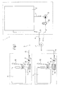
- number 1 indicates as a whole a laundry washing machine comprising a wash tub 2 housing a perforated revolving laundry drum (not shown); and an automatic dispensing and metering device 3 for feeding measured quantities of laundering products, e.g. detergent, softener, freshener, etc., into tub 2.
- laundering products e.g. detergent, softener, freshener, etc.
- device 3 comprises a water circuit 4 closed by tub 2; two inlets 5 for respective products; and metering means 6, which are interposed between inlets 5 and circuit 4, and, as explained in detail below, inject measured quantities of products into circuit 4, when water flows along circuit 4, to feed a water-product mixture into tub 2.
- circuit 4 comprises a delivery branch 7 extending from tub 2 to metering means 6 to supply metering means 6 with wash water from tub 2; and a return branch 8 extending from metering means 6 to tub 2 to feed a water-product mixture into tub 2.
- Circuit 4 also comprises a pump 9 located along delivery branch 7 to pump water from tub 2 along circuit 4 via a solenoid valve 10, which is located along delivery branch 7, downstream from pump 9, and is activated by an external signal as a function of the programmed wash cycle.
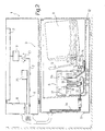
- Each inlet 5 is defined by a fast-fit connector to a respective container 11, which may be replaceable, as in the Figure 1 and 2 embodiment, or refillable, as in the Figure 3 and 4 embodiment.
- containers 11 are housed in a pull-out drawer 12 formed in a base 13 of machine 1.
- drawer 12 houses two side by side containers 11 (only one shown in Figure 2 ) defined, in the example shown, by respective disposable cans of enough product for numerous wash cycles.
- Each inlet 5 (only one shown in Figure 2 ) is defined by the mouth of a respective tank 14 connectable to relative container 11 by a tap 15, the inlet of which is connected in fluidtight manner to an opening in container 11, before container 11 is placed inside drawer 12, and the outlet of which is connected in fluidtight manner to the mouth of tank 14 to connect container 11 to tank 14.
- Tap 15 comprises a spring-operated valve normally set to a closed position (not shown), and which is set to an open position (shown in Figure 2 ) by means of an external lever 16 hand-operated by the user once tap 15 is connected to tank 14, so container 11 can be connected and disconnected easily, with no leakage, and the product can be gravity-fed into tank 14 only after tap 15 is inserted through inlet 5.
- metering means 6 are housed, together with container 11 and tank 14, inside drawer 12, and comprise, for each inlet 5, a pump 17 ( Figure 2 shows pumps 17 of both containers 11); an intake conduit 18 connecting the inlet of pump 17 to relative tank 14; and a feed conduit 19 connecting the outlet of pump 17 to a mixer 21 via a one-way valve 20.
- Mixer 21 to which both feed conduits 19 of relative pumps 17 are connected, defines a portion of circuit 4 connecting the outlet of delivery branch 7 to the inlet of return branch 8, and communicates on one side with delivery branch 7 via a one-way valve 22 to receive water from tub 2, in use, and on the other side with return branch 8 via a one-way valve 23 to feed a water-product mixture into tub 2.
- Pumps 17 are controlled, as described below, by a central control unit 25 housed in a main body of machine 1 over base 13, and connected to pumps 17 by a multipole cable 24, which, together with delivery branch 7 and return branch 8, extends from the main body of machine 1 to base 13 through an outside sleeve, and through an extensible member located inside base 13 and outside drawer 12 to permit extension of cable 24 and branches 7 and 8 when drawer 12 is pulled out of base 13.
- a central control unit 25 housed in a main body of machine 1 over base 13, and connected to pumps 17 by a multipole cable 24, which, together with delivery branch 7 and return branch 8, extends from the main body of machine 1 to base 13 through an outside sleeve, and through an extensible member located inside base 13 and outside drawer 12 to permit extension of cable 24 and branches 7 and 8 when drawer 12 is pulled out of base 13.
- device 3 For each tank 14, device 3 comprises two optical level sensors 26 connected to central control unit 25 by multipole cable 24.
- central control unit 25 activates the pump 17 connected to the detergent container 11 (hereinafter indicated 17a for the sake of clarity).
- pump 17a detergent is drawn from tank 14 along relative intake conduit 18 and injected along relative feed conduit 19 into mixer 21 at a high enough pressure to open valve 20.
- the detergent mixes with the circulating water to form a water-detergent mixture, and is fed along return branch 8 into the laundry inside tub 2.
- the detergent is metered automatically, by central control unit 25 controlling the operating time of pump 17a determined by central control unit 25 on the basis of the programmed cycle parameters, e.g. type and quantity of laundry, type of wash cycle, etc.
- central control unit 25 stops pump 17a, thus cutting off detergent supply to mixer 21.
- valve 10 is closed, and water no longer flows along circuit 4.
- sensors 26 transmit respective signals to central control unit 25, which disables respective pump 17 until container 11 is changed, and preferably also lights up a "no-product" alarm signal on a display of machine 1.
- central control unit 25 is designed to operate pumps 17 of product tanks 14 simultaneously or successively, and to keep each pump 17 operating for the time taken to dispense the required amount of the relative product.
- the two containers 11 housed inside drawer 12 are two refillable tanks (only one shown in Figure 4 ), each of which contains enough product for numerous wash cycles, is housed inside a support 27 integral with base 13, and has a tilting lid 28 to enable the user to top up the product.
- each container 11 has a tubular opening 29, which, when the container 11 is housed in support 27 ( Figure 4 ), is inserted partly inside the initial portion of a channel 30 formed in support 27 and defining said inlet 5 for the product inside container 11.
- Each opening 29 has a ball valve, which, when the container is housed in support 27 ( Figure 4 ), is held in an open position by a pin integral with support 27, and, when the container is detached from support 27 (not shown), e.g. for cleaning, closes opening 29 to prevent product leakage from the container.
- metering means 6 comprise a hydropneumatic metering device 31, in turn comprising a cylinder 32, and a piston 33 slid by compressed air inside cylinder 32. More specifically, cylinder 32 is closed at one end, and, at the opposite end, is fitted through in fluidtight sliding manner with the rod of piston 33, an end portion of which, integral with the rod, mates in fluidtight manner with the lateral wall of cylinder 32, and divides cylinder 32 internally into a first chamber communicating with the delivery side of a compressor 34, and a closed second chamber housing a spring 35 compressed between the closed end of cylinder 32 and the end portion of piston 33.
- piston 33 has an end portion, which mates in fluidtight sliding manner with the lateral wall of a tubular member to define, inside the tubular member, a variable-volume chamber 36, which, as explained in detail below, stores the measured amount of product drawn from container 11 by hydropneumatic metering device 31, pending injection into circuit 4.
- chamber 36 communicates, on one side, with channel 30 via a one-way valve 37 only allowing product flow into chamber 36, and, on the other side, with mixer 21 via a feed channel 38 and a one-way valve 39 only allowing outflow of the product from chamber 36.
- compressor 34 is housed in the main body of machine 1, and is connected to each hydropneumatic metering device 31 by a respective tube 40 to selectively feed compressed air to relative cylinders 32 via a three-position solenoid valve 41.
- an external command activates compressor 34, which feeds compressed air to cylinder 32 of container 11 of the product to be dispensed, e.g. detergent, so as to overcome the resistance of spring 35, slide piston 33 inwards of cylinder 32, and so increase the volume of chamber 36 and form a sufficiently low pressure inside chamber 36 to open valve 37 and feed the product into chamber 36.
- compressor 34 which feeds compressed air to cylinder 32 of container 11 of the product to be dispensed, e.g. detergent, so as to overcome the resistance of spring 35, slide piston 33 inwards of cylinder 32, and so increase the volume of chamber 36 and form a sufficiently low pressure inside chamber 36 to open valve 37 and feed the product into chamber 36.
- each metering means 6 - be it a pump 9 or a hydropneumatic metering device 31 - is associated with a respective container 11, and operates regardless of the presence or number of other metering means 6.
- operation of machine 1 as described above also applies, regardless of whether device 3 comprises only one inlet 5 for one container 11, or more than two inlets 5 for respective containers 11.
Abstract
Description
- The present invention relates to a laundry washing machine.
- More specifically, the present invention relates to a laundry washing machine of the type comprising a device for automatically dispensing and metering at least one laundering product.
- At present, washing machines of the above type are practically only used professionally, on account of the highly complex design of the automatic product dispensing and metering device, which makes the machine both expensive and difficult to use.
- For example
EP 0 196 398 discloses a device for delivering metered quantities of liquid products to a utiliser, comprising a plunger-type pump and a pump control means including a programmable memory of any type, such as a memory card, by means of which the number of strokes of the plunger of the pump, and consequently the quantity of liquid delivered thereby, can be determined. The pump is connected at its suction side to a plurality of liquid containers by a network of pipes each having a controllable valve, the opening and closing of which can be controlled by the pump control means in dependence on the programme stored in the programmable memory. A typical utiliser for such device is an industrial washing machine which can thus receive metered quantities of liquid detergents and other additives in place of powders used conventionally without recourse to liquid metering devices of other type and greater complexity. -
DE 4 000 378 discloses a dosing apparatus adapted to feed an additive into a clothes or dishes washing machine using an electrically operated valve system, the dosing apparatus having precautions for the dosing chamber to be flushed automatically with a rinsing fluid. -
DE 3 822 246 -
WO 2006 043118 discloses an ejector system for adding liquid detergent to washing machines which may be annexed to the existing system of the washing machine in such a way that the user can choose at any time between washing with powder detergents or with liquid detergents. The Ejector System consists of an ejector, an electromagnetic valve, a non-return valve and a container (4). - It is an object of the present invention to provide a laundry washing machine featuring an automatic product dispensing and metering device, and which, at the same time, is straightforward, economical, and particularly suitable for home use.
- According to the present invention, there is provided a laundry washing machine as claimed in
Claim 1 and, preferably, in any one of the Claims depending directly or indirectly onClaim 1. - A number of non-limiting embodiments of the present invention will be described by way of example with reference to the accompanying drawings, in which:
-
Figure 1 shows an operating block diagram of a preferred embodiment of the machine according to the present invention; -
Figure 2 shows a schematic detail of theFigure 1 machine; -
Figure 3 shows an operating block diagram of a variation of theFigure 1 machine; -
Figure 4 shows a schematic detail of theFigure 3 machine. - With reference to
Figures 1 and3 ,number 1 indicates as a whole a laundry washing machine comprising awash tub 2 housing a perforated revolving laundry drum (not shown); and an automatic dispensing andmetering device 3 for feeding measured quantities of laundering products, e.g. detergent, softener, freshener, etc., intotub 2. - More specifically,
device 3 comprises awater circuit 4 closed bytub 2; twoinlets 5 for respective products; and metering means 6, which are interposed betweeninlets 5 andcircuit 4, and, as explained in detail below, inject measured quantities of products intocircuit 4, when water flows alongcircuit 4, to feed a water-product mixture intotub 2. For this purpose,circuit 4 comprises adelivery branch 7 extending fromtub 2 to metering means 6 to supply metering means 6 with wash water fromtub 2; and areturn branch 8 extending frommetering means 6 totub 2 to feed a water-product mixture intotub 2.Circuit 4 also comprises apump 9 located alongdelivery branch 7 to pump water fromtub 2 alongcircuit 4 via asolenoid valve 10, which is located alongdelivery branch 7, downstream frompump 9, and is activated by an external signal as a function of the programmed wash cycle. - Each
inlet 5 is defined by a fast-fit connector to arespective container 11, which may be replaceable, as in theFigure 1 and2 embodiment, or refillable, as in theFigure 3 and4 embodiment. In both cases,containers 11 are housed in a pull-outdrawer 12 formed in abase 13 ofmachine 1. - More specifically, with reference to the
Figure 1 and2 example,drawer 12 houses two side by side containers 11 (only one shown inFigure 2 ) defined, in the example shown, by respective disposable cans of enough product for numerous wash cycles. Each inlet 5 (only one shown inFigure 2 ) is defined by the mouth of arespective tank 14 connectable torelative container 11 by atap 15, the inlet of which is connected in fluidtight manner to an opening incontainer 11, beforecontainer 11 is placed insidedrawer 12, and the outlet of which is connected in fluidtight manner to the mouth oftank 14 to connectcontainer 11 totank 14. -
Tap 15 comprises a spring-operated valve normally set to a closed position (not shown), and which is set to an open position (shown inFigure 2 ) by means of anexternal lever 16 hand-operated by the user oncetap 15 is connected totank 14, socontainer 11 can be connected and disconnected easily, with no leakage, and the product can be gravity-fed intotank 14 only aftertap 15 is inserted throughinlet 5. - As shown in
Figure 2 ,metering means 6 are housed, together withcontainer 11 andtank 14, insidedrawer 12, and comprise, for eachinlet 5, a pump 17 (Figure 2 showspumps 17 of both containers 11); anintake conduit 18 connecting the inlet ofpump 17 torelative tank 14; and afeed conduit 19 connecting the outlet ofpump 17 to amixer 21 via a one-way valve 20. -
Mixer 21, to which bothfeed conduits 19 ofrelative pumps 17 are connected, defines a portion ofcircuit 4 connecting the outlet ofdelivery branch 7 to the inlet ofreturn branch 8, and communicates on one side withdelivery branch 7 via a one-way valve 22 to receive water fromtub 2, in use, and on the other side withreturn branch 8 via a one-way valve 23 to feed a water-product mixture intotub 2. -
Pumps 17 are controlled, as described below, by a central control unit 25 housed in a main body ofmachine 1 overbase 13, and connected topumps 17 by amultipole cable 24, which, together withdelivery branch 7 andreturn branch 8, extends from the main body ofmachine 1 tobase 13 through an outside sleeve, and through an extensible member located insidebase 13 andoutside drawer 12 to permit extension ofcable 24 andbranches drawer 12 is pulled out ofbase 13. - For each
tank 14,device 3 comprises twooptical level sensors 26 connected to central control unit 25 bymultipole cable 24. - Operation of
machine 1 will now be described, as of the instant in which, on the basis of the programmed cycle ofmachine 1, a measured quantity of product, e.g. detergent, is to be added to the laundry. At this point, while a known external hydraulic circuit (not shown) feeds wash water intotub 2, an electric command, activated by the timer ofmachine 1, opensvalve 10 and operatespump 9, which pumps water fromtub 2 intocircuit 4 at a high enough pressure to openvalves mixer 21. As the water flows throughmixer 21,valves 20 ofrespective feed conduits 19 prevent it from flowing intofeed conduits 19 torespective pumps 17. - Once water is circulating inside
circuit 4, central control unit 25 activates thepump 17 connected to the detergent container 11 (hereinafter indicated 17a for the sake of clarity). Whenpump 17a is activated, detergent is drawn fromtank 14 alongrelative intake conduit 18 and injected alongrelative feed conduit 19 intomixer 21 at a high enough pressure to openvalve 20. - Inside
mixer 21, the detergent mixes with the circulating water to form a water-detergent mixture, and is fed alongreturn branch 8 into the laundry insidetub 2. - The detergent is metered automatically, by central control unit 25 controlling the operating time of
pump 17a determined by central control unit 25 on the basis of the programmed cycle parameters, e.g. type and quantity of laundry, type of wash cycle, etc. - Consequently, after a given time lapse corresponding to the amount of detergent to be used in the wash, central control unit 25
stops pump 17a, thus cutting off detergent supply tomixer 21. - After a further given time lapse, during which
pump 9 continues pumping water alongcircuit 4 to remove all traces of detergent frommixer 21 and to flushcircuit 4,pump 9 is also stopped,valve 10 is closed, and water no longer flows alongcircuit 4. - When
container 11 runs out and the product level insidetank 14 falls,sensors 26 transmit respective signals to central control unit 25, which disablesrespective pump 17 untilcontainer 11 is changed, and preferably also lights up a "no-product" alarm signal on a display ofmachine 1. - For the sake of clarity, the above example is limited to feeding a measured quantity of only one product, i.e. detergent, into
tub 2. - If the wash program calls for using two products simultaneously, however, central control unit 25 is designed to operate
pumps 17 ofproduct tanks 14 simultaneously or successively, and to keep eachpump 17 operating for the time taken to dispense the required amount of the relative product. - In the variation shown in
Figures 3 and4 , the twocontainers 11 housed insidedrawer 12 are two refillable tanks (only one shown inFigure 4 ), each of which contains enough product for numerous wash cycles, is housed inside asupport 27 integral withbase 13, and has a tiltinglid 28 to enable the user to top up the product. - At the bottom, each
container 11 has atubular opening 29, which, when thecontainer 11 is housed in support 27 (Figure 4 ), is inserted partly inside the initial portion of achannel 30 formed insupport 27 and defining saidinlet 5 for the product insidecontainer 11. - Each
opening 29 has a ball valve, which, when the container is housed in support 27 (Figure 4 ), is held in an open position by a pin integral withsupport 27, and, when the container is detached from support 27 (not shown), e.g. for cleaning, closes opening 29 to prevent product leakage from the container. - As shown in
Figure 4 , for eachinlet 5, metering means 6 comprise ahydropneumatic metering device 31, in turn comprising acylinder 32, and a piston 33 slid by compressed air insidecylinder 32. More specifically,cylinder 32 is closed at one end, and, at the opposite end, is fitted through in fluidtight sliding manner with the rod of piston 33, an end portion of which, integral with the rod, mates in fluidtight manner with the lateral wall ofcylinder 32, and dividescylinder 32 internally into a first chamber communicating with the delivery side of acompressor 34, and a closed second chamber housing aspring 35 compressed between the closed end ofcylinder 32 and the end portion of piston 33. - At the opposite end, piston 33 has an end portion, which mates in fluidtight sliding manner with the lateral wall of a tubular member to define, inside the tubular member, a variable-volume chamber 36, which, as explained in detail below, stores the measured amount of product drawn from
container 11 byhydropneumatic metering device 31, pending injection intocircuit 4. - More specifically, chamber 36 communicates, on one side, with
channel 30 via a one-way valve 37 only allowing product flow into chamber 36, and, on the other side, withmixer 21 via a feed channel 38 and a one-way valve 39 only allowing outflow of the product from chamber 36. - As shown in
Figures 3 and4 ,compressor 34 is housed in the main body ofmachine 1, and is connected to eachhydropneumatic metering device 31 by arespective tube 40 to selectively feed compressed air torelative cylinders 32 via a three-position solenoid valve 41. - This variation of
machine 1 operates in the same way asmachine 1 described with reference toFigures 1 and2 , with the exception of the metering mode adopted. - That is, once
pump 9 is operated and water begins to circulate incircuit 4, an external command activatescompressor 34, which feeds compressed air tocylinder 32 ofcontainer 11 of the product to be dispensed, e.g. detergent, so as to overcome the resistance ofspring 35, slide piston 33 inwards ofcylinder 32, and so increase the volume of chamber 36 and form a sufficiently low pressure inside chamber 36 to openvalve 37 and feed the product into chamber 36. - Since the amount of product drawn is proportional to the volume of chamber 36 and, therefore, to the travel of piston 33, automatic metering, in this case, is a function of the position of piston 33 inside
cylinder 32. - When
compressor 34 is deactivated,spring 35 pushes piston 33 outwards, thus rapidly reducing the volume of chamber 36 and expelling the product from the chamber at a high enough pressure to openvalve 39 and feed the product intomixer 21. - To conclude, it should be pointed out that, in the above embodiments, the number of
inlets 5 is purely indicative. In fact, as will be clear from the above description, in both embodiments, each metering means 6 - be it apump 9 or a hydropneumatic metering device 31 - is associated with arespective container 11, and operates regardless of the presence or number of other metering means 6. As such, operation ofmachine 1 as described above also applies, regardless of whetherdevice 3 comprises only oneinlet 5 for onecontainer 11, or more than twoinlets 5 forrespective containers 11.
Claims (24)
- A laundry washing machine comprising a wash tub (2), and an automatic dispensing and metering device (3) for dispensing and metering at least one laundering product drawn from a respective container (11) containing a sufficient amount of product for numerous wash cycles; said dispensing and metering device (3) comprising an inlet (5) for the product; a water circuit (4) closed by the tub (2); and product metering means (6) interposed between the inlet (5) and the circuit (4) to inject a measured amount of product into the circuit (4) when water flows along the circuit (4), the machine (1) being characterized in that said circuit (4) comprises:- a mixing area (21) communicating with an outlet of said product metering means (6);- a delivery branch (7) and a return branch (8) connected to each other at one end by the tub (2), and at the other end by the mixing area (21).
- A machine as claimed in Claim 1, wherein the inlet (5) is defined by a fast-fit connector to the container (11).
- A machine as claimed in Claim 1 or 2, wherein said mixing area (21) communicates with said outlet of said product metering means (6) via first valve means (20; 39).
- A machine as claimed in Claim 3, wherein the first valve means comprise a first one-way valve (20; 39) calibrated to allow the product into the mixing area (21).
- A machine as claimed in Claim 3 or 4, wherein the delivery branch (7) and the return branch (8) communicate with the mixing area (21) via second valve means (22, 23).
- A machine as claimed in Claim 5, wherein the second valve means (22, 23) comprise a second one-way valve (22) calibrated to allow water flow to the mixing area (21); and a third one-way valve (23) calibrated to allow outflow of a water and product mixture from the mixing area (21).
- A machine as claimed in one of Claims 1 to 6, wherein the dispensing and metering device (3) comprises a first pump (9) along the delivery branch (7).
- A machine as claimed in Claim 7, wherein the dispensing and metering device (3) comprises a two-position valve (10) located along the delivery branch (7), downstream from the first pump (9).
- A machine as claimed in Claim 7 or 8, wherein the metering means (6) comprise a second pump (17) having an inlet communicating with the container (11), and an outlet communicating with the circuit (4).
- A machine as claimed in Claims 3 and 9, wherein the first valve means (20) are located between the mixing area (21) and the outlet of the second pump (17) to allow the product into the mixing area (21).
- A machine as claimed in Claim 9 or 10, wherein the container (11) is a disposable container; and the metering means (6) comprise a product tank (14); the tank (14) having a mouth defining said inlet (5) and communicating, in use, with the relative container (11).
- A machine as claimed in Claim 11, wherein a tap (15) is fitted to the inlet (5) to connect the container (11) in fluidtight manner to the tank (14).
- A machine as claimed in Claim 12, wherein the tap (15) has a valve normally set to a closed position, and which can be set manually to an open position.
- A machine as claimed in Claim 13, and comprising a hand-operated lever (16) for moving the valve into the open position.
- A machine as claimed in any one of Claims 9 to 14, wherein the second pump (17) is time-controlled.
- A machine as claimed in one of Claims 1 to 8, wherein the metering means (6) comprise a hydropneumatic metering device (31).
- A machine as claimed in Claim 16, wherein the hydropneumatic metering device (31) comprises a compressor (34); a cylinder (32); and a piston (33) sliding inside the cylinder (32) and comprising a first end portion, which is fitted in fluidtight manner to the cylinder (32) and divides the cylinder (32) internally into a first chamber communicating with an outlet of the compressor (34), and a second chamber housing a return spring (35) of the piston (33).
- A machine as claimed in Claims 3 and 17, wherein the piston (33) comprises a second end portion outside the cylinder (32) and defining a movable wall of a variable-volume chamber (36) interposed between the container (11) and the mixing area (21).
- A machine as claimed in Claim 18, wherein the variable-volume chamber (36) communicates with the container (11) via a calibrated fourth one-way valve (37), which allows intake of the product by suction into the variable-volume chamber (36), when the volume of the variable-volume chamber (36) is increased by displacement of the piston (33).
- A machine as claimed in Claim 18 or 19, wherein the first valve means (39) are located between the mixing area (21) and the variable-volume chamber (36) to allow into the mixing area (21) the product expelled from the variable-volume chamber (36) when the volume of the variable-volume chamber (36) is reduced by return displacement of the piston (33).
- A machine as claimed in any one of the foregoing Claims, and comprising at least two inlets (5) connected to respective metering means (6).
- A machine as claimed in Claim 21, wherein said at least two metering means (6) are connected in parallel to the mixing area (21).
- A machine as claimed in any one of the foregoing Claims, and comprising a pull-out drawer (12) housing the container (11).
- A machine as claimed in Claim 23, wherein the drawer (12) also houses at least part of said metering means (6).
Priority Applications (10)
| Application Number | Priority Date | Filing Date | Title |
|---|---|---|---|
| PL07111681T PL2011913T3 (en) | 2007-07-03 | 2007-07-03 | Laundry washing machine |
| EP07111681A EP2011913B1 (en) | 2007-07-03 | 2007-07-03 | Laundry washing machine |
| ES07111681T ES2363705T3 (en) | 2007-07-03 | 2007-07-03 | COLADA WASHING MACHINE. |
| AT07111681T ATE497046T1 (en) | 2007-07-03 | 2007-07-03 | WASHING MACHINE |
| DE602007012225T DE602007012225D1 (en) | 2007-07-03 | 2007-07-03 | Washing machine |
| AU2008271488A AU2008271488A1 (en) | 2007-07-03 | 2008-02-13 | Laundry washing machine |
| RU2010116501/12A RU2467108C2 (en) | 2007-07-03 | 2008-02-13 | Washing machine |
| US12/666,210 US20100139328A1 (en) | 2007-07-03 | 2008-02-13 | Method of controlling a tumble laundry drier |
| BRPI0813790-0A2A BRPI0813790A2 (en) | 2007-07-03 | 2008-02-13 | WASHING MACHINE |
| PCT/EP2008/051741 WO2009003731A1 (en) | 2007-07-03 | 2008-02-13 | Laundry washing machine |
Applications Claiming Priority (1)
| Application Number | Priority Date | Filing Date | Title |
|---|---|---|---|
| EP07111681A EP2011913B1 (en) | 2007-07-03 | 2007-07-03 | Laundry washing machine |
Publications (2)
| Publication Number | Publication Date |
|---|---|
| EP2011913A1 EP2011913A1 (en) | 2009-01-07 |
| EP2011913B1 true EP2011913B1 (en) | 2011-01-26 |
Family
ID=38656619
Family Applications (1)
| Application Number | Title | Priority Date | Filing Date |
|---|---|---|---|
| EP07111681A Not-in-force EP2011913B1 (en) | 2007-07-03 | 2007-07-03 | Laundry washing machine |
Country Status (10)
| Country | Link |
|---|---|
| US (1) | US20100139328A1 (en) |
| EP (1) | EP2011913B1 (en) |
| AT (1) | ATE497046T1 (en) |
| AU (1) | AU2008271488A1 (en) |
| BR (1) | BRPI0813790A2 (en) |
| DE (1) | DE602007012225D1 (en) |
| ES (1) | ES2363705T3 (en) |
| PL (1) | PL2011913T3 (en) |
| RU (1) | RU2467108C2 (en) |
| WO (1) | WO2009003731A1 (en) |
Families Citing this family (19)
| Publication number | Priority date | Publication date | Assignee | Title |
|---|---|---|---|---|
| KR101482110B1 (en) * | 2008-05-23 | 2015-01-13 | 엘지전자 주식회사 | Washing machine |
| KR101491574B1 (en) * | 2008-10-31 | 2015-02-11 | 삼성전자 주식회사 | Washing Machine |
| US8555678B2 (en) | 2008-12-09 | 2013-10-15 | Lg Electronics Inc. | Washing machine system and washing method |
| EP2251480B1 (en) | 2009-05-11 | 2017-11-29 | Electrolux Home Products Corporation N.V. | Laundry washing appliance |
| PL2251481T3 (en) * | 2009-05-11 | 2019-08-30 | Electrolux Home Products Corporation N.V. | Laundry washing appliance |
| EP2540902B1 (en) * | 2011-06-30 | 2020-05-13 | Electrolux Home Products Corporation N.V. | Laundry washing machine |
| BR112014004387B1 (en) | 2011-08-31 | 2021-05-04 | Lg Electronics, Inc | garment care apparatus |
| KR101993223B1 (en) | 2012-10-10 | 2019-06-26 | 엘지전자 주식회사 | Laundry Treating Apparatus |
| WO2014121824A1 (en) * | 2013-02-06 | 2014-08-14 | Electrolux Appliances Aktiebolag | Laundry washing machine |
| PL2959050T3 (en) | 2013-02-06 | 2022-08-01 | Electrolux Appliances Aktiebolag | Laundry washing machine |
| KR102255022B1 (en) | 2013-07-03 | 2021-05-24 | 삼성전자주식회사 | Detergent automatic providing apparatus and washing machine having the same |
| TR201719293T3 (en) | 2013-07-08 | 2019-05-21 | Arcelik As | A DISHWASHER INCLUDING A LIQUID / GEL DETERGENT DOSING UNIT AND STORAGE UNIT CLEANING SYSTEM. |
| KR102296969B1 (en) * | 2014-03-21 | 2021-09-02 | 삼성전자주식회사 | Washing machine |
| DE102014105711A1 (en) * | 2014-04-23 | 2015-10-29 | Miele & Cie. Kg | Method of operating a washing machine and washing machine |
| US10914028B2 (en) | 2015-08-04 | 2021-02-09 | Whirlpool Corporation | Laundry treating appliance with stain station |
| IT201600086018A1 (en) * | 2016-08-18 | 2018-02-18 | Illinois Tool Works | AUXILIARY DEVICE FOR THE DISTRIBUTION OF WASHING LIQUIDS TO A WASHING MACHINE |
| CN108570827A (en) * | 2017-03-14 | 2018-09-25 | 青岛海尔滚筒洗衣机有限公司 | A kind of detergent box and washing machine of washing machine |
| CN114108265A (en) * | 2020-09-01 | 2022-03-01 | 博西华电器(江苏)有限公司 | Washing machine |
| US20220380962A1 (en) * | 2021-05-26 | 2022-12-01 | The Procter & Gamble Company | Supply system for laundry treatment composition |
Family Cites Families (67)
| Publication number | Priority date | Publication date | Assignee | Title |
|---|---|---|---|---|
| US2197382A (en) * | 1938-02-15 | 1940-04-16 | Eugene V Myers | Dishwashing machine |
| NL257769A (en) * | 1960-07-15 | |||
| US3683944A (en) * | 1971-01-25 | 1972-08-15 | Sybron Corp | Control apparatus for washer-sterilizer |
| US3949902A (en) * | 1973-06-11 | 1976-04-13 | Thompson Frank B | Portable dispensing bar |
| US3935719A (en) * | 1973-08-06 | 1976-02-03 | A-T-O Inc. | Recirculating |
| CH561902A5 (en) * | 1973-12-17 | 1975-05-15 | Bolla Ernesto Lino | Additive injection into rinsing and washing plant lines - double piston injection valve uses existing feed water pressure |
| US3940994A (en) * | 1974-08-01 | 1976-03-02 | Varian Associates | High pressure sample injection apparatus and method |
| US4218264A (en) * | 1979-03-09 | 1980-08-19 | Federighi George B | Dishwasher utilizing pump impeller suction for feeding detergent, sanitizing agent and rinse aid in timed sequences |
| IT8234023V0 (en) * | 1982-06-09 | 1982-06-09 | Zanussi A Spa Industrie | DISPENSER DISPENSER DEVICE FOR WASHING MACHINE. |
| IT1208525B (en) * | 1985-03-28 | 1989-07-10 | Elton Chemical Spa | COMPUTERIZED DEVICE, WITH PROGRAMMABLE MEMORY CARDS, FOR DOSING LIQUID PRODUCTS, TO BE PLACED IN INDUSTRIAL WASHING MACHINES. |
| DE3636384A1 (en) * | 1986-10-25 | 1988-04-28 | Licentia Gmbh | Dishwasher or washing machine, in particular for the household, with a metering device for liquid detergent |
| DE3822246A1 (en) * | 1988-07-01 | 1990-01-04 | Bauknecht Hausgeraete | Metering device for liquids |
| US4932227A (en) * | 1988-09-21 | 1990-06-12 | Lever Brothers Company | Apparatus and method for automatically injecting laundry treating chemicals into a commercial washing machine |
| US4981024A (en) * | 1989-02-03 | 1991-01-01 | Belco Equipment, Inc. | Apparatus, system, and method for dispensing laundry chemicals |
| US5014211A (en) * | 1989-06-16 | 1991-05-07 | Diversey Corporation | Microprocessor controlled liquid chemical delivery system and method |
| DE4000378C2 (en) * | 1990-01-09 | 1994-05-05 | Aweco Kunststofftech Geraete | Device for dosing a liquid additive for washing machines or dishwashers |
| IT225633Y1 (en) * | 1991-02-18 | 1997-01-13 | Zanussi Elettrodomestici | DISPENSER OF DETERGENTS AND OR LIQUID ADDITIVES FOR WASHING MACHINE |
| US5681400A (en) * | 1992-03-12 | 1997-10-28 | Ecolab Inc. | Self-optimizing detergent controller for controlling variable additive concentration level in a warewashing machine |
| US5564595A (en) * | 1995-02-15 | 1996-10-15 | Minissian; Kevin G. | Chemical dispensing system |
| US5746238A (en) * | 1995-03-31 | 1998-05-05 | Ecolab, Inc. | Liquid chemical dilution and dosing system |
| US5590686A (en) * | 1995-05-02 | 1997-01-07 | Dober Chemical Corp. | Liquid delivery systems |
| US5826749A (en) * | 1996-02-22 | 1998-10-27 | Nova Controls | Multiplexed system for dispensing multiple chemicals to multiple destinations |
| US5601413A (en) * | 1996-02-23 | 1997-02-11 | Great Plains Industries, Inc. | Automatic low fluid shut-off method for a pumping system |
| US5870906A (en) * | 1996-04-03 | 1999-02-16 | Denisar; Richard A. | Automatic dispensing device |
| US5782109A (en) * | 1996-05-06 | 1998-07-21 | Ecolab Inc. | Dispenser |
| DE19654090C1 (en) * | 1996-12-23 | 1998-03-05 | Henkel Ecolab Gmbh & Co Ohg | Washing machine detergent feed |
| US5758521A (en) * | 1997-02-07 | 1998-06-02 | Roberts; Perrion D. | Automatic detergent and fabric softener dispensing system |
| US5887769A (en) * | 1997-05-14 | 1999-03-30 | Kidd; Terrel G. | Disinfectant dispensing apparatus |
| US6055831A (en) * | 1997-05-31 | 2000-05-02 | Barbe; David J. | Pressure sensor control of chemical delivery system |
| US5975352A (en) * | 1997-08-28 | 1999-11-02 | Ecolab Inc. | Dispenser |
| US5897671A (en) * | 1997-11-07 | 1999-04-27 | Diversey Lever, Inc. | System and method for washing machine cycle identification and chemical dosing identification |
| US6463611B1 (en) * | 1999-04-02 | 2002-10-15 | Ecolab, Inc. | Apparatus for dispensing incompatible chemicals to a common utilization point |
| US6377868B1 (en) * | 1999-10-28 | 2002-04-23 | Ecolab Inc. | Data processing system for managing chemical product usage |
| US6403551B1 (en) * | 1999-11-10 | 2002-06-11 | Eco-Safe, L.L.C. | Autonomous cleaning apparatus and method |
| WO2001081238A1 (en) * | 2000-04-25 | 2001-11-01 | Shell Internationale Research Maatschappij B.V. | Process and machine for mixing liquids |
| US6557732B2 (en) * | 2000-07-19 | 2003-05-06 | The Procter & Gamble Company | Detergent pack |
| US7624600B2 (en) * | 2000-07-25 | 2009-12-01 | Whirlpool Corporation | Modular laundry system with horizontally arranged cabinet module |
| US20070266740A9 (en) * | 2000-07-25 | 2007-11-22 | Kendall James W | Vertical laundry module |
| US6401499B1 (en) * | 2000-07-31 | 2002-06-11 | Maytag Corporation | Air pump bulk dispenser |
| US6434977B1 (en) * | 2000-10-06 | 2002-08-20 | Ark-Les Corporation | Automatic laundry aid dispenser for washing machine |
| US6434772B1 (en) * | 2000-10-24 | 2002-08-20 | U.N.X. Incorporated | Chemical dispensing system |
| US20020092878A1 (en) * | 2001-01-16 | 2002-07-18 | Seton Ian William | Electronic dispenser |
| DE10107558A1 (en) * | 2001-02-17 | 2002-09-19 | Dornier Gmbh Lindauer | Dosing device for lubricants |
| US6418958B1 (en) * | 2001-04-02 | 2002-07-16 | Betzdearborn, Inc. | Dual solid chemical feed system |
| US6637478B2 (en) * | 2001-07-10 | 2003-10-28 | Ecolab Inc. | Fill station for a liquid dispensing system |
| US6671914B2 (en) * | 2001-12-20 | 2004-01-06 | Maytag Corporation | Chemical sharing system and method for washing appliances |
| JP4197893B2 (en) * | 2001-12-28 | 2008-12-17 | 株式会社オメガ | Method and apparatus for producing washing / cleaning sterilizing water |
| US6792637B2 (en) * | 2002-01-08 | 2004-09-21 | U.S. Chemical Corporation | Automatic detergent dispensing system for a warewasher |
| US7036175B2 (en) * | 2002-02-19 | 2006-05-02 | Maytag Corporation | Washing machine with pay activated bulk detergent dispenser |
| AU2003251390A1 (en) * | 2002-06-03 | 2003-12-19 | Steiner-Atlantic Corp. | Wrinkle deterring and textile cleaning processes and apparatuses |
| KR20030096795A (en) * | 2002-06-17 | 2003-12-31 | 삼성전자주식회사 | Detergent box of drum type washing machine |
| US20040084065A1 (en) * | 2002-11-04 | 2004-05-06 | Edelmann David Charles | Systems and methods for controlling warewasher wash cycle duration, detecting water levels and priming warewasher chemical feed lines |
| US7725970B2 (en) * | 2002-11-25 | 2010-06-01 | Robert J. Tuttle | Control system and method for supplying detergent and other fluids to multiple washing machines |
| KR20040093614A (en) * | 2003-04-30 | 2004-11-06 | 삼성전자주식회사 | Washing machine |
| US20040245899A1 (en) * | 2003-06-05 | 2004-12-09 | Cho Han Ki | Washing machine pedestal |
| KR101010689B1 (en) * | 2004-02-06 | 2011-01-24 | 엘지전자 주식회사 | Pedestal for washing machine |
| US20050183208A1 (en) * | 2004-02-20 | 2005-08-25 | The Procter & Gamble Company | Dual mode laundry apparatus and method using the same |
| HRP20040980A2 (en) * | 2004-10-18 | 2006-08-31 | Frida Darko | The ejector system for adding liquid detergent to washing machines |
| US7398787B2 (en) * | 2004-10-18 | 2008-07-15 | Unilever Home & Personal Care Usa Division Of Conopco, Inc. | Automatic dispensing device for laundry care composition |
| US7481081B2 (en) * | 2004-11-23 | 2009-01-27 | Unilever Home & Personal Care Usa Division Of Conopco, Inc. | Automatic stand-alone dispensing device for laundry care composition |
| US20060117811A1 (en) * | 2004-12-06 | 2006-06-08 | Kinnetz Roger E | Liquid detergent dispensing system for automatic washer |
| DE102006023995A1 (en) * | 2005-05-23 | 2006-12-28 | Lg Electronic Inc. | Laundry treatment device, has front cover unit arranged between main bodies for covering of gap between main bodies and designed on same height as gap, where unit has accumulation kit that is located on top side of one of bodies |
| DE102005050083B4 (en) * | 2005-10-18 | 2011-11-03 | Miele & Cie. Kg | Dosing device for liquid additive for a household appliance |
| US20070151305A1 (en) * | 2005-12-30 | 2007-07-05 | Kendall James W | Modular laundry system with vertical module |
| US7562543B2 (en) * | 2005-12-30 | 2009-07-21 | Whirlpool Corporation | Vertical laundry module with backsplash |
| US8240514B2 (en) * | 2006-03-30 | 2012-08-14 | Diversey, Inc. | Powdered and liquid chemical dispensing and distribution system |
| WO2008016683A1 (en) * | 2006-08-01 | 2008-02-07 | The Procter & Gamble Company | Receiving apparatus |
-
2007
- 2007-07-03 PL PL07111681T patent/PL2011913T3/en unknown
- 2007-07-03 ES ES07111681T patent/ES2363705T3/en active Active
- 2007-07-03 AT AT07111681T patent/ATE497046T1/en not_active IP Right Cessation
- 2007-07-03 DE DE602007012225T patent/DE602007012225D1/en active Active
- 2007-07-03 EP EP07111681A patent/EP2011913B1/en not_active Not-in-force
-
2008
- 2008-02-13 RU RU2010116501/12A patent/RU2467108C2/en not_active IP Right Cessation
- 2008-02-13 BR BRPI0813790-0A2A patent/BRPI0813790A2/en not_active IP Right Cessation
- 2008-02-13 WO PCT/EP2008/051741 patent/WO2009003731A1/en active Application Filing
- 2008-02-13 AU AU2008271488A patent/AU2008271488A1/en not_active Abandoned
- 2008-02-13 US US12/666,210 patent/US20100139328A1/en not_active Abandoned
Also Published As
| Publication number | Publication date |
|---|---|
| ATE497046T1 (en) | 2011-02-15 |
| BRPI0813790A2 (en) | 2014-12-30 |
| RU2010116501A (en) | 2011-11-10 |
| AU2008271488A1 (en) | 2009-01-08 |
| EP2011913A1 (en) | 2009-01-07 |
| DE602007012225D1 (en) | 2011-03-10 |
| US20100139328A1 (en) | 2010-06-10 |
| ES2363705T3 (en) | 2011-08-12 |
| WO2009003731A1 (en) | 2009-01-08 |
| RU2467108C2 (en) | 2012-11-20 |
| PL2011913T3 (en) | 2011-11-30 |
Similar Documents
| Publication | Publication Date | Title |
|---|---|---|
| EP2011913B1 (en) | Laundry washing machine | |
| US9506183B2 (en) | Laundry washing appliance with dosing dispenser | |
| US8171757B2 (en) | Dispensing system for liquid or viscous treating agents for use in a washing machine, and washing machine | |
| EP3460120B1 (en) | Laundry washing appliance | |
| EP3071742B1 (en) | Laundry washing machine with detergent drawer comprising a control panel | |
| US8052805B2 (en) | Method for automatically flushing a bulk dispensing system in a cleaning appliance | |
| EP2142697B1 (en) | Laundry washing machine | |
| CN109957936B (en) | Washing machine | |
| CN109957906B (en) | Washing machine | |
| US10117561B2 (en) | Dishwasher comprising a cleaning system for a liquid/gel detergent dosing unit and a receptacle unit | |
| CN101688350A (en) | Automatically controlled washing machine | |
| US3021863A (en) | Dispensing mechanism | |
| AU2017281507B2 (en) | Operating method of a laundry washing machine and laundry washing machine implementing such method | |
| WO2006043118A1 (en) | The ejector system for adding liquid detergent to washing machines | |
| RU2777547C1 (en) | Washing machine |
Legal Events
| Date | Code | Title | Description |
|---|---|---|---|
| PUAI | Public reference made under article 153(3) epc to a published international application that has entered the european phase |
Free format text: ORIGINAL CODE: 0009012 |
|
| AK | Designated contracting states |
Kind code of ref document: A1 Designated state(s): AT BE BG CH CY CZ DE DK EE ES FI FR GB GR HU IE IS IT LI LT LU LV MC MT NL PL PT RO SE SI SK TR |
|
| AX | Request for extension of the european patent |
Extension state: AL BA HR MK RS |
|
| 17P | Request for examination filed |
Effective date: 20090311 |
|
| 17Q | First examination report despatched |
Effective date: 20090408 |
|
| AKX | Designation fees paid |
Designated state(s): AT BE BG CH CY CZ DE DK EE ES FI FR GB GR HU IE IS IT LI LT LU LV MC MT NL PL PT RO SE SI SK TR |
|
| GRAP | Despatch of communication of intention to grant a patent |
Free format text: ORIGINAL CODE: EPIDOSNIGR1 |
|
| GRAS | Grant fee paid |
Free format text: ORIGINAL CODE: EPIDOSNIGR3 |
|
| GRAA | (expected) grant |
Free format text: ORIGINAL CODE: 0009210 |
|
| AK | Designated contracting states |
Kind code of ref document: B1 Designated state(s): AT BE BG CH CY CZ DE DK EE ES FI FR GB GR HU IE IS IT LI LT LU LV MC MT NL PL PT RO SE SI SK TR |
|
| REG | Reference to a national code |
Ref country code: GB Ref legal event code: FG4D |
|
| REG | Reference to a national code |
Ref country code: CH Ref legal event code: EP |
|
| REG | Reference to a national code |
Ref country code: IE Ref legal event code: FG4D |
|
| REF | Corresponds to: |
Ref document number: 602007012225 Country of ref document: DE Date of ref document: 20110310 Kind code of ref document: P |
|
| REG | Reference to a national code |
Ref country code: DE Ref legal event code: R096 Ref document number: 602007012225 Country of ref document: DE Effective date: 20110310 |
|
| RAP2 | Party data changed (patent owner data changed or rights of a patent transferred) |
Owner name: ELECTROLUX HOME PRODUCTS CORPORATION N.V. |
|
| REG | Reference to a national code |
Ref country code: NL Ref legal event code: VDEP Effective date: 20110126 |
|
| LTIE | Lt: invalidation of european patent or patent extension |
Effective date: 20110126 |
|
| RAP2 | Party data changed (patent owner data changed or rights of a patent transferred) |
Owner name: ELECTROLUX HOME PRODUCTS CORPORATION N.V. |
|
| PG25 | Lapsed in a contracting state [announced via postgrant information from national office to epo] |
Ref country code: LV Free format text: LAPSE BECAUSE OF FAILURE TO SUBMIT A TRANSLATION OF THE DESCRIPTION OR TO PAY THE FEE WITHIN THE PRESCRIBED TIME-LIMIT Effective date: 20110126 Ref country code: LT Free format text: LAPSE BECAUSE OF FAILURE TO SUBMIT A TRANSLATION OF THE DESCRIPTION OR TO PAY THE FEE WITHIN THE PRESCRIBED TIME-LIMIT Effective date: 20110126 Ref country code: GR Free format text: LAPSE BECAUSE OF FAILURE TO SUBMIT A TRANSLATION OF THE DESCRIPTION OR TO PAY THE FEE WITHIN THE PRESCRIBED TIME-LIMIT Effective date: 20110427 Ref country code: PT Free format text: LAPSE BECAUSE OF FAILURE TO SUBMIT A TRANSLATION OF THE DESCRIPTION OR TO PAY THE FEE WITHIN THE PRESCRIBED TIME-LIMIT Effective date: 20110526 Ref country code: SE Free format text: LAPSE BECAUSE OF FAILURE TO SUBMIT A TRANSLATION OF THE DESCRIPTION OR TO PAY THE FEE WITHIN THE PRESCRIBED TIME-LIMIT Effective date: 20110126 Ref country code: IS Free format text: LAPSE BECAUSE OF FAILURE TO SUBMIT A TRANSLATION OF THE DESCRIPTION OR TO PAY THE FEE WITHIN THE PRESCRIBED TIME-LIMIT Effective date: 20110526 |
|
| REG | Reference to a national code |
Ref country code: ES Ref legal event code: FG2A Ref document number: 2363705 Country of ref document: ES Kind code of ref document: T3 Effective date: 20110812 |
|
| PG25 | Lapsed in a contracting state [announced via postgrant information from national office to epo] |
Ref country code: BG Free format text: LAPSE BECAUSE OF FAILURE TO SUBMIT A TRANSLATION OF THE DESCRIPTION OR TO PAY THE FEE WITHIN THE PRESCRIBED TIME-LIMIT Effective date: 20110426 Ref country code: NL Free format text: LAPSE BECAUSE OF FAILURE TO SUBMIT A TRANSLATION OF THE DESCRIPTION OR TO PAY THE FEE WITHIN THE PRESCRIBED TIME-LIMIT Effective date: 20110126 Ref country code: AT Free format text: LAPSE BECAUSE OF FAILURE TO SUBMIT A TRANSLATION OF THE DESCRIPTION OR TO PAY THE FEE WITHIN THE PRESCRIBED TIME-LIMIT Effective date: 20110126 Ref country code: FI Free format text: LAPSE BECAUSE OF FAILURE TO SUBMIT A TRANSLATION OF THE DESCRIPTION OR TO PAY THE FEE WITHIN THE PRESCRIBED TIME-LIMIT Effective date: 20110126 Ref country code: SI Free format text: LAPSE BECAUSE OF FAILURE TO SUBMIT A TRANSLATION OF THE DESCRIPTION OR TO PAY THE FEE WITHIN THE PRESCRIBED TIME-LIMIT Effective date: 20110126 Ref country code: CY Free format text: LAPSE BECAUSE OF FAILURE TO SUBMIT A TRANSLATION OF THE DESCRIPTION OR TO PAY THE FEE WITHIN THE PRESCRIBED TIME-LIMIT Effective date: 20110126 Ref country code: BE Free format text: LAPSE BECAUSE OF FAILURE TO SUBMIT A TRANSLATION OF THE DESCRIPTION OR TO PAY THE FEE WITHIN THE PRESCRIBED TIME-LIMIT Effective date: 20110126 Ref country code: PL Free format text: LAPSE BECAUSE OF FAILURE TO SUBMIT A TRANSLATION OF THE DESCRIPTION OR TO PAY THE FEE WITHIN THE PRESCRIBED TIME-LIMIT Effective date: 20110126 |
|
| PG25 | Lapsed in a contracting state [announced via postgrant information from national office to epo] |
Ref country code: EE Free format text: LAPSE BECAUSE OF FAILURE TO SUBMIT A TRANSLATION OF THE DESCRIPTION OR TO PAY THE FEE WITHIN THE PRESCRIBED TIME-LIMIT Effective date: 20110126 Ref country code: DK Free format text: LAPSE BECAUSE OF FAILURE TO SUBMIT A TRANSLATION OF THE DESCRIPTION OR TO PAY THE FEE WITHIN THE PRESCRIBED TIME-LIMIT Effective date: 20110126 |
|
| PG25 | Lapsed in a contracting state [announced via postgrant information from national office to epo] |
Ref country code: CZ Free format text: LAPSE BECAUSE OF FAILURE TO SUBMIT A TRANSLATION OF THE DESCRIPTION OR TO PAY THE FEE WITHIN THE PRESCRIBED TIME-LIMIT Effective date: 20110126 Ref country code: RO Free format text: LAPSE BECAUSE OF FAILURE TO SUBMIT A TRANSLATION OF THE DESCRIPTION OR TO PAY THE FEE WITHIN THE PRESCRIBED TIME-LIMIT Effective date: 20110126 Ref country code: SK Free format text: LAPSE BECAUSE OF FAILURE TO SUBMIT A TRANSLATION OF THE DESCRIPTION OR TO PAY THE FEE WITHIN THE PRESCRIBED TIME-LIMIT Effective date: 20110126 |
|
| REG | Reference to a national code |
Ref country code: PL Ref legal event code: T3 |
|
| PLBE | No opposition filed within time limit |
Free format text: ORIGINAL CODE: 0009261 |
|
| STAA | Information on the status of an ep patent application or granted ep patent |
Free format text: STATUS: NO OPPOSITION FILED WITHIN TIME LIMIT |
|
| PG25 | Lapsed in a contracting state [announced via postgrant information from national office to epo] |
Ref country code: MT Free format text: LAPSE BECAUSE OF FAILURE TO SUBMIT A TRANSLATION OF THE DESCRIPTION OR TO PAY THE FEE WITHIN THE PRESCRIBED TIME-LIMIT Effective date: 20110126 |
|
| 26N | No opposition filed |
Effective date: 20111027 |
|
| REG | Reference to a national code |
Ref country code: DE Ref legal event code: R097 Ref document number: 602007012225 Country of ref document: DE Effective date: 20111027 |
|
| PG25 | Lapsed in a contracting state [announced via postgrant information from national office to epo] |
Ref country code: MC Free format text: LAPSE BECAUSE OF NON-PAYMENT OF DUE FEES Effective date: 20110731 |
|
| REG | Reference to a national code |
Ref country code: CH Ref legal event code: PL |
|
| REG | Reference to a national code |
Ref country code: IE Ref legal event code: MM4A |
|
| PG25 | Lapsed in a contracting state [announced via postgrant information from national office to epo] |
Ref country code: LI Free format text: LAPSE BECAUSE OF NON-PAYMENT OF DUE FEES Effective date: 20110731 Ref country code: CH Free format text: LAPSE BECAUSE OF NON-PAYMENT OF DUE FEES Effective date: 20110731 |
|
| PG25 | Lapsed in a contracting state [announced via postgrant information from national office to epo] |
Ref country code: IE Free format text: LAPSE BECAUSE OF NON-PAYMENT OF DUE FEES Effective date: 20110703 |
|
| PG25 | Lapsed in a contracting state [announced via postgrant information from national office to epo] |
Ref country code: LU Free format text: LAPSE BECAUSE OF NON-PAYMENT OF DUE FEES Effective date: 20110703 |
|
| PGFP | Annual fee paid to national office [announced via postgrant information from national office to epo] |
Ref country code: PL Payment date: 20130625 Year of fee payment: 7 |
|
| PG25 | Lapsed in a contracting state [announced via postgrant information from national office to epo] |
Ref country code: TR Free format text: LAPSE BECAUSE OF FAILURE TO SUBMIT A TRANSLATION OF THE DESCRIPTION OR TO PAY THE FEE WITHIN THE PRESCRIBED TIME-LIMIT Effective date: 20110126 |
|
| PG25 | Lapsed in a contracting state [announced via postgrant information from national office to epo] |
Ref country code: HU Free format text: LAPSE BECAUSE OF FAILURE TO SUBMIT A TRANSLATION OF THE DESCRIPTION OR TO PAY THE FEE WITHIN THE PRESCRIBED TIME-LIMIT Effective date: 20110126 |
|
| PGFP | Annual fee paid to national office [announced via postgrant information from national office to epo] |
Ref country code: DE Payment date: 20130722 Year of fee payment: 7 Ref country code: ES Payment date: 20130729 Year of fee payment: 7 |
|
| PGFP | Annual fee paid to national office [announced via postgrant information from national office to epo] |
Ref country code: FR Payment date: 20130722 Year of fee payment: 7 Ref country code: GB Payment date: 20130719 Year of fee payment: 7 |
|
| PGFP | Annual fee paid to national office [announced via postgrant information from national office to epo] |
Ref country code: IT Payment date: 20130725 Year of fee payment: 7 |
|
| REG | Reference to a national code |
Ref country code: DE Ref legal event code: R119 Ref document number: 602007012225 Country of ref document: DE |
|
| GBPC | Gb: european patent ceased through non-payment of renewal fee |
Effective date: 20140703 |
|
| REG | Reference to a national code |
Ref country code: FR Ref legal event code: ST Effective date: 20150331 |
|
| PG25 | Lapsed in a contracting state [announced via postgrant information from national office to epo] |
Ref country code: DE Free format text: LAPSE BECAUSE OF NON-PAYMENT OF DUE FEES Effective date: 20150203 Ref country code: IT Free format text: LAPSE BECAUSE OF NON-PAYMENT OF DUE FEES Effective date: 20140703 |
|
| REG | Reference to a national code |
Ref country code: DE Ref legal event code: R119 Ref document number: 602007012225 Country of ref document: DE Effective date: 20150203 |
|
| PG25 | Lapsed in a contracting state [announced via postgrant information from national office to epo] |
Ref country code: FR Free format text: LAPSE BECAUSE OF NON-PAYMENT OF DUE FEES Effective date: 20140731 Ref country code: GB Free format text: LAPSE BECAUSE OF NON-PAYMENT OF DUE FEES Effective date: 20140703 |
|
| REG | Reference to a national code |
Ref country code: PL Ref legal event code: LAPE |
|
| PG25 | Lapsed in a contracting state [announced via postgrant information from national office to epo] |
Ref country code: PL Free format text: LAPSE BECAUSE OF NON-PAYMENT OF DUE FEES Effective date: 20140703 |
|
| REG | Reference to a national code |
Ref country code: ES Ref legal event code: FD2A Effective date: 20160205 |
|
| PG25 | Lapsed in a contracting state [announced via postgrant information from national office to epo] |
Ref country code: ES Free format text: LAPSE BECAUSE OF NON-PAYMENT OF DUE FEES Effective date: 20140704 |