EP2011730A1 - Safety braking system - Google Patents
Safety braking system Download PDFInfo
- Publication number
- EP2011730A1 EP2011730A1 EP07111804A EP07111804A EP2011730A1 EP 2011730 A1 EP2011730 A1 EP 2011730A1 EP 07111804 A EP07111804 A EP 07111804A EP 07111804 A EP07111804 A EP 07111804A EP 2011730 A1 EP2011730 A1 EP 2011730A1
- Authority
- EP
- European Patent Office
- Prior art keywords
- brake
- wheel
- safety
- braking system
- levers
- Prior art date
- Legal status (The legal status is an assumption and is not a legal conclusion. Google has not performed a legal analysis and makes no representation as to the accuracy of the status listed.)
- Granted
Links
Images


Classifications
-
- B—PERFORMING OPERATIONS; TRANSPORTING
- B62—LAND VEHICLES FOR TRAVELLING OTHERWISE THAN ON RAILS
- B62L—BRAKES SPECIALLY ADAPTED FOR CYCLES
- B62L3/00—Brake-actuating mechanisms; Arrangements thereof
- B62L3/08—Mechanisms specially adapted for braking more than one wheel
-
- B—PERFORMING OPERATIONS; TRANSPORTING
- B60—VEHICLES IN GENERAL
- B60T—VEHICLE BRAKE CONTROL SYSTEMS OR PARTS THEREOF; BRAKE CONTROL SYSTEMS OR PARTS THEREOF, IN GENERAL; ARRANGEMENT OF BRAKING ELEMENTS ON VEHICLES IN GENERAL; PORTABLE DEVICES FOR PREVENTING UNWANTED MOVEMENT OF VEHICLES; VEHICLE MODIFICATIONS TO FACILITATE COOLING OF BRAKES
- B60T11/00—Transmitting braking action from initiating means to ultimate brake actuator without power assistance or drive or where such assistance or drive is irrelevant
- B60T11/04—Transmitting braking action from initiating means to ultimate brake actuator without power assistance or drive or where such assistance or drive is irrelevant transmitting mechanically
- B60T11/046—Using cables
Definitions
- the present invention is related to a safety braking system, and more particularly to one that effectively improve braking mechanism of a mini type or linear 2-wheel vehicle, e.g., a bike or motorcycle, upgrade safety, and minimize injuries due to improper control, application, or operation of a brake.
- a mini type or linear 2-wheel vehicle e.g., a bike or motorcycle
- a brake is a safety device, also an extremely important component for vehicles; improper application or poor design of the brake frequently results in traffic accident even causes the driver and/or a third party to sustain major hazard or loss.
- the brake operates by having linings to tightly pull or clip a brake disc or drum.
- a light-duty vehicle e.g., a bike
- it is usually designed with linings to directly pull or clip tight a rim of a wheel of the bike.
- a hand brake is usually adapted to a bike, motorcycle or other light-duty vehicle while larger vehicles usually operate mechanical brake or power aided brake.
- all these types of brakes are found with many drawbacks, and the most serious and thus most important drawback is insufficient braking force or difficulty in managing the braking force, contributing to or aggravate major traffic accident or injuries.
- a linear two-wheel bike is most popular among light-duty vehicles.
- a bike not only relied upon as a short-range transportation means, but also used as for traveling, sporting, or racing purpose provides diversified applications.
- a light-duty motorcycle is another familiar type of linear two-wheel vehicle.
- a linear two-wheel bike or motorcycle it is usually disposed with a hand brake and provided each to both of a right and a left handles.
- the left hand brake controls application of a brake for the front wheel; and the right one, the rear wheel.
- the primary purpose of the present invention is to provide safe brake, which is mounted to a bike, motorcycle or any other vehicle provided with two independent hand brakes for both wheels, that makes sure of always braking the rear wheel before braking the front wheel disregarding the left or the right hand brake is applied first for achieving safe effects by helping stabilize the frame and prevent from turning over.
- a safe brake of the present invention is designed with two stages of braking mechanism, the primary mechanism and the secondary power transmission mechanism. Both hand brakes are linked to the primary mechanism where the braking force is transferred to the secondary power transmission mechanism for the secondary power transmission mechanism to transfer braking force to both brakes on a front wheel and a rear wheels to realize the control of having applied brake to the rear wheel first before the rear wheel.
- the secondary power transmission mechanism in the safe brake of the present invention is related to a sheave comprised of two rollers. Two rollers move relatively to each other when the primary mechanism is subject to a braking force applied by a brake lever thus to cause a front wheel brake and a rear wheel brake to apply braking the front and the rear wheels in sequence.
- Each roller further includes a larger wheel and a smaller wheel with each wheel provided with a groove along its edge.
- a cable winding up the larger wheel is then connected to a lead cable engaging the rear wheel brake; and a cable winding up the smaller wheel is then connected to a lead cable engaging the front wheel brake.
- both brake rollers are not in the same diameter
- a pull force exercised by the lead cable of the rear wheel brake placed on the larger roller is faster and greater than that by the lead cable of the front wheel brake placed on the smaller roller since the perimeter of the larger roller is longer than that of the smaller roller to ensure that the rear wheel is braked before the front wheel.
- Design and construction of two relative rollers in a safety braking system of the present invention provide a type and functions of a pulley in physics to feature effort-saving; and the ratio between both rollers may vary depending on the model of the vehicle while allowing design or adjust braking force and the ratio of braking forces respectively applied on the front wheel and the rear wheel depending on the model of the vehicle.
- the roller may be directly pulled closer or farther by a brake cable of the brake lever, or the brake cable is pulled by revolution using a pinion.
- a safety braking system many improved design for the construction of a safety braking system may be realized according to the present invention.
- two arc levers of the safety braking system pivoted to each other at the center of each arc lever; one side of the arc lever is connected to the brake cable of the brake lever while the other side in relation to the pivoting point is disposed with two wheels each with groove along its edge for each arc lever.
- the cable surrounding those two wheels each with groove along its edge at the distal end of the pivoting point is connected to the lead cable of the front wheel brake.
- an amount of change in the lead cable connected to where between two wheels with groove along its edge disposed to the outer side of the arc lever is greater than that of the lead cable disposed on an inner side of the arc lever to permit the rear wheel to be braked first before the front wheel.
- a brake lever brake cable is connected to one side of the arc lever; two wheels each with a groove along its edge are disposed on each arc lever on the opposite side to the pivoting point; two wheels on one arc lever are fixed to a same point on the arc lever and hold a lead cable jointly with another two wheels with a groove along its edge to cause the lead cable to create different amount of change.
- a brake lever brake cable is connected to one side of the arc lever; two wheels each with a groove along its edge are disposed to an arc lever on the opposite side to the pivoting point; and the lead cable held by another two wheels each with a groove along its edge is fixed to another arc lever to achieve the purpose of having a time delay in applying brake respectively for the front and the rear wheel of the vehicle.
- multiple wheels each with a groove along its edge that connect the front and the rear brakes to be individually mounted to such that the position of those wheels each with a groove along its edge controlling the front wheel is closer to the pivoting point than those controlling the rear wheel is thus to produce different braking force and time delay; and a locating mechanism is provided for the rider to readjust the position of each wheel with a groove along its edge according to his/her riding behavior for improved safety.
- the present invention is adapted to a bike, a light-duty motorcycle or any other light-duty vehicle provided with both left and right brake levers to respectively control braking a front wheel and a rear wheel, and the bike is taken as an example for the purpose hereunder.
- the bike is provided with a right handlebar and a left handlebar 91 respectively mounted with a manual brake lever 92; and a brake cable 93 connects both brake levers 92 to a safety braking system 1 of the present invention.
- the safety braking system 1 is mounted to a head tube 96 or where between both handlebars 91, or coupled to a stem 94 and connected to a lead cable 951 and a lead cable 952 respectively of a front wheel brake 941 and a rear wheel brake 942. Accordingly, when either of both brake levers 92 is pulled, the rear wheel brake 942 applies first a brake on the rear wheel and then the front wheel 941 applies a brake on the front wheel.
- the safety braking system 1 mounted to the head tube 96 is comprised of two arc levers 10, 20 pivoted to each other at a pivoting point 30; two brake cables 93 are connected to one side of both arc levers 10, 20 to form a primary mechanism.
- the pivoting point 30 On the opposite side of the pivoting point 30 are respectively provided with two rollers 11, 21 to form a secondary power transmission mechanism.
- each roller 11, 21 includes a larger wheel a and smaller wheel b with each provided with a groove on its edge; both larger wheels a hold the lead cable 952 of the rear wheel brake; and both smaller wheels b hold the lead cable 951 of the front wheel brake.
- a distance between centers of both rollers 11, 21 is designated as L1 when the brake cable 93 connected to the brake lever is not yet pulled as illustrated in Fig. 4 ; when the brake cable 93 is pulled in a direction marked by an arrow G1 in Fig. 5 , a braking force is created to move the primary mechanism comprised of both arc levers 10, 20.
- the primary mechanism transfers the braking force to the secondary power transmission mechanism, and the distance between both centers of rollers 11, 21 disposed on the opposite side of both arc levers 10, 20 relatively increase to that as designated by L2.
- both of the lead cable 952 of the rear brake held by both larger wheels a of two rollers 11, 21 and the lead cable 951 of the front brake held by both smaller wheels b of two rollers 11, 21 create a pull force (as designated by arrows G2 and G3) for the secondary power transmission mechanism to respectively transfer the braking force to the front and the rear brakes; and the rear wheel brake 942 will first brake the rear wheel before the front wheel brake 941 applying a brake on the front wheel.
- a safety braking system 2 is disposed with a holding base 40 fixed to the head tube 96; an upper roller 41 and a lower roller 42 are provided on the holding base 40; the lower roller 42 may be provided as a stationary roller or a roller permitted to move downwardly; the upper roller 41 against the lower roller 42 displaces along a channel disposed on the holding base; and the brake cable 93 of the brake lever is directly connected to the upper roller 42.
- the brake cable 93 pulls the upper roller 42 to move upwardly.
- Each of both the upper and the lower rollers 41, 42 includes a larger wheel a and a smaller wheel b each having a groove along its edge; both larger wheels a hold a lead cable 952 of the rear brake and both smaller wheels b hold a lead cable 951 of the front brake; and both lead cables 951, 952 pass through a lead cable holding frame 44.
- a relative distance between both centers of the upper and the lower rollers 41, 42 is designated as L3 as illustrated in Fig. 8 when a brake cable 93 connected to a brake lever is not yet pulled.
- a brake cable 93 is pulled in a direction marked by an arrow G4 as illustrated in Fig. 9 , a braking force is created, the upper roller 41 moves upward for the relative distance between both centers of the upper and the lower rollers 41, 42 is increased up to L4 ; and the braking force is transferred to both lead cables 951, 952 respectively of the front and the rear brakes.
- both of the lead cable 952 of the rear brake held by both larger wheels a of two rollers 11, 21 and the lead cable 951 of the front brake held by both smaller wheels b of two rollers 11, 21 create a pull force (as designated by arrows G5 and G6) and the rear wheel brake 942 will first brake the rear wheel before the front wheel brake 941 applying a brake on the front wheel.
- the safety braking system 2 of the present invention is mounted to at where appropriately between the right and the left handlebars 91 or the stem 94 connecting both handlebars and the head tube; and the safety braking system 2 may be mounted horizontally as illustrated in Fig. 10 or vertically as illustrated in Fig. 6 .
- the brake cable of the brake lever may be connected to a rack, i.e., the primary mechanism; and a gear set connected to both rollers bits the rack.
- a rack i.e., the primary mechanism
- a gear set connected to both rollers bits the rack.
- Each roller includes a larger wheel and a smaller wheel with each having a groove along its edge, and a distance between both centers of two rollers relatively increases when the brake cable pulls both rollers on the rack, a variable summary design of the present invention protected by a patent.
- the safety braking system 2 mounted to the head tube 96 has two arc levers 10, 20 pivoted to each other at a pivoting point 30.
- One side of both arc levers 10, 20 is connected to a brake cable 93 of the brake lever to form a primary mechanism; on the opposite side of the pivoting point 30 are respectively provided with two rollers a, b, with each having a groove along its edge, to form a secondary power transmission mechanism.
- Both wheels a hold a lead cable 952 of the rear wheel brake and another two wheels b hold a lead cable 951 of the front wheel brake.
- a distance between both centers of two wheels a is designated as L5 and a distance between both centers of two wheels b, L6.
- a braking force is generated for the primary mechanism comprised of both arc levers to move for transferring the braking force to the secondary power transmission mechanism and both distances L5, L6 on the opposite side of both arc levers increase up to that respectively designated as L7 and L8 .
- both of the lead cable 952 of the rear brake held by both wheels a and the lead cable 951 of the front brake held by both wheels b create a pull force (as designated by arrows G8 and G9) for the secondary power transmission mechanism to respectively transfer the braking force to the front and the rear brakes; and the rear wheel brake 942 will first brake the rear wheel before the front wheel brake 941 applying a brake on the front wheel.
- a distance D1 between an axes of the wheel a and the pivoting point 30 is greater than D2, a distance between an axis of the wheel b and the pivoting point.
- a locating mechanism is disposed to both arc levers 10, 20 to allow both wheels a, b to adjust their positions on the arc levers as desired.
- multiple holes 101, 201 are provided on both arc levers 10, 20; and a locking member S penetrates through selected holes 101, 102 on both arc levers 10, 20 and those wheels each having a groove along its edge to secure both arc levers 10, 20 to those wheels.
- the locking member S may be related to a screw or a fast connector.
- a chute F and a slide V combined with and placed in the chute F are disposed on each of both arc levers.
- the locking member S may be related to a screw or a fast connector. With the locating mechanism, the rider may adjust the position of each wheel having a groove along its edge according to his/her particular riding behavior to achieve the optimal braking effects.
- Fig. 16 one wheel a and one wheel b on one arc lever are locked at a same point (concentrically) to achieve purpose of having the amount of change of the lead cable 952 become greater than that of the lead cable 951 thus to allow the rear wheel brake connected to the lead cable 952 to act first.
- Fig. 17 both ends respectively of the lead cable 951 and the lead cable 952 are directly fixed to the arc lever 20 to achieve the same purpose.
- the preferred embodiment illustrated in Figs. 16 and 17 may be provided with the same locating mechanism as that mounted to the preferred embodiment illustrated in Figs. 13 , 14 , and 15 to achieve the purpose of adjusting the position of each wheel having a groove along its edge on the arc levers.
- the safety braking system 2 of the present invention may be mounted to where appropriately between both handlebars 91, on the stem 94 that connects both handlebars 91 and the head tube vertically or horizontally.
Landscapes
- Engineering & Computer Science (AREA)
- Mechanical Engineering (AREA)
- Transportation (AREA)
- Transmission Of Braking Force In Braking Systems (AREA)
- Steering Devices For Bicycles And Motorcycles (AREA)
Abstract
Description
- The present invention is related to a safety braking system, and more particularly to one that effectively improve braking mechanism of a mini type or linear 2-wheel vehicle, e.g., a bike or motorcycle, upgrade safety, and minimize injuries due to improper control, application, or operation of a brake.
- A brake is a safety device, also an extremely important component for vehicles; improper application or poor design of the brake frequently results in traffic accident even causes the driver and/or a third party to sustain major hazard or loss.
- Essentially the brake operates by having linings to tightly pull or clip a brake disc or drum. In a light-duty vehicle, e.g., a bike, it is usually designed with linings to directly pull or clip tight a rim of a wheel of the bike. A hand brake is usually adapted to a bike, motorcycle or other light-duty vehicle while larger vehicles usually operate mechanical brake or power aided brake. However, all these types of brakes are found with many drawbacks, and the most serious and thus most important drawback is insufficient braking force or difficulty in managing the braking force, contributing to or aggravate major traffic accident or injuries.
- For being light, convenient, easy manipulation, sold at affordable price, a linear two-wheel bike is most popular among light-duty vehicles. A bike not only relied upon as a short-range transportation means, but also used as for traveling, sporting, or racing purpose provides diversified applications. A light-duty motorcycle is another familiar type of linear two-wheel vehicle.
- Upon riding on a bike or a motorcycle, weight of the vehicle is supported only on a straight line. A bike or motorcycle for being instable due to having higher center of gravity, is vulnerable to deflect or slant or even slip and fall when subject to external force or voluntary swing to left or right by its rider. In case of applying a brake directly with a front wheel without applying a brake a rear wheel of the bike or the motorcycle, the already higher center of gravity would even more forward to significantly reduce stability of the frame and the rider to frequently result in accident. Therefore, while applying a brake on a bike or a motorcycle of linear two-wheel construction, the braking must be first applied on its rear wheel before applying a brake to the front wheel for safety reason. This is particularly important for a vehicle adapted with a front shock absorber. Braking the front wheel first on riding the vehicle adapted with the front shock absorber will cause the shock absorber to sink to bring further the center of gravity of the rider who is already in a position of comparatively higher center of gravity. Leaning forward plus the acceleration force would cause the vehicle to toss around and seriously threaten the life of the rider.
- In a linear two-wheel bike or motorcycle, it is usually disposed with a hand brake and provided each to both of a right and a left handles. The left hand brake controls application of a brake for the front wheel; and the right one, the rear wheel. However, it may be the opposite case to some frames of the vehicles. That is, there is the absence of mandatory principle or standard on whether which hand brake should control which wheel, and that is totally left for the frame manufacturer, a bodywork shop or a rider to determine on discretion. This makes the vehicle particularly danger to one who is not a frequent rider or is using a brake stranger to him/her.
- Furthermore, a rider when encountered by an emergency tends to naturally apply the hand brake mounted on the side where the imminent threaten is approaching instead of braking the rear wheel first before breaking the front wheel. That makes even dangerous to the rider has to do the right action in a quick response in facing an emergency situation.
- The primary purpose of the present invention is to provide safe brake, which is mounted to a bike, motorcycle or any other vehicle provided with two independent hand brakes for both wheels, that makes sure of always braking the rear wheel before braking the front wheel disregarding the left or the right hand brake is applied first for achieving safe effects by helping stabilize the frame and prevent from turning over.
- To achieve the purpose, a safe brake of the present invention is designed with two stages of braking mechanism, the primary mechanism and the secondary power transmission mechanism. Both hand brakes are linked to the primary mechanism where the braking force is transferred to the secondary power transmission mechanism for the secondary power transmission mechanism to transfer braking force to both brakes on a front wheel and a rear wheels to realize the control of having applied brake to the rear wheel first before the rear wheel.
- The secondary power transmission mechanism in the safe brake of the present invention is related to a sheave comprised of two rollers. Two rollers move relatively to each other when the primary mechanism is subject to a braking force applied by a brake lever thus to cause a front wheel brake and a rear wheel brake to apply braking the front and the rear wheels in sequence.
- Each roller further includes a larger wheel and a smaller wheel with each wheel provided with a groove along its edge. A cable winding up the larger wheel is then connected to a lead cable engaging the rear wheel brake; and a cable winding up the smaller wheel is then connected to a lead cable engaging the front wheel brake. Accordingly, upon applying a brake, all motive forces will pull the brake roller whether the right or the left hand brake lever is exercised to cause both rollers to have relative displacement for the brake rollers to operate the brake cable to realize consistent brake control mode. Whereas both brake rollers are not in the same diameter, a pull force exercised by the lead cable of the rear wheel brake placed on the larger roller is faster and greater than that by the lead cable of the front wheel brake placed on the smaller roller since the perimeter of the larger roller is longer than that of the smaller roller to ensure that the rear wheel is braked before the front wheel.
- Design and construction of two relative rollers in a safety braking system of the present invention provide a type and functions of a pulley in physics to feature effort-saving; and the ratio between both rollers may vary depending on the model of the vehicle while allowing design or adjust braking force and the ratio of braking forces respectively applied on the front wheel and the rear wheel depending on the model of the vehicle.
- The roller may be directly pulled closer or farther by a brake cable of the brake lever, or the brake cable is pulled by revolution using a pinion.
- Furthermore, many improved design for the construction of a safety braking system may be realized according to the present invention. For example, two arc levers of the safety braking system pivoted to each other at the center of each arc lever; one side of the arc lever is connected to the brake cable of the brake lever while the other side in relation to the pivoting point is disposed with two wheels each with groove along its edge for each arc lever. The cable surrounding those two wheels each with groove along its edge at the distal end of the pivoting point is connected to the lead cable of the front wheel brake. By changing a distance between the wheel with groove along its edge and the pivoting point, an amount of change in the lead cable connected to where between two wheels with groove along its edge disposed to the outer side of the arc lever is greater than that of the lead cable disposed on an inner side of the arc lever to permit the rear wheel to be braked first before the front wheel. Alternatively, a brake lever brake cable is connected to one side of the arc lever; two wheels each with a groove along its edge are disposed on each arc lever on the opposite side to the pivoting point; two wheels on one arc lever are fixed to a same point on the arc lever and hold a lead cable jointly with another two wheels with a groove along its edge to cause the lead cable to create different amount of change. Furthermore, a brake lever brake cable is connected to one side of the arc lever; two wheels each with a groove along its edge are disposed to an arc lever on the opposite side to the pivoting point; and the lead cable held by another two wheels each with a groove along its edge is fixed to another arc lever to achieve the purpose of having a time delay in applying brake respectively for the front and the rear wheel of the vehicle.
- By providing those three types of installations, multiple wheels each with a groove along its edge that connect the front and the rear brakes to be individually mounted to such that the position of those wheels each with a groove along its edge controlling the front wheel is closer to the pivoting point than those controlling the rear wheel is thus to produce different braking force and time delay; and a locating mechanism is provided for the rider to readjust the position of each wheel with a groove along its edge according to his/her riding behavior for improved safety.
-
-
Fig. 1 is a schematic view showing a bike mounted with a safety braking system of the present invention. -
Fig. 2 is a perspective view of a first preferred embodiment of the present invention. -
Fig. 3 is a sectional view of the first preferred embodiment of the present invention. -
Fig. 4 is a floor plan of the first preferred embodiment of the present invention. -
Fig. 5 is a schematic view showing an operating status of the preferred embodiment of the present invention. -
Fig. 6 is a perspective view showing a second preferred embodiment of the present invention. -
Fig. 7 is a sectional view of the second preferred embodiment of the present invention. -
Fig. 8 is a floor plan of the second preferred embodiment of the present invention. -
Fig. 9 is a schematic view showing an operating status of the second preferred embodiment of the present invention. -
Fig. 10 is a schematic view showing that the second preferred embodiment of the present invention is laterally mounted. -
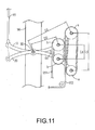
Fig. 11 is a perspective view showing a perspective view of a third preferred embodiment of the present invention. -
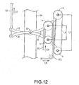
Fig. 12 is a schematic view showing the third preferred embodiment of the present invention. -
Fig. 13 is a schematic view showing a locating mechanism in the present invention. -
Fig. 14 is a schematic view showing another locating mechanism in the present invention. -
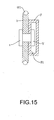
Fig. 15 is a sectional view of the locating mechanism taken fromFig. 14 . -
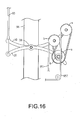
Fig. 16 is a front view showing another preferred embodiment yet of the present invention. -
Fig. 17 is a front view showing another preferred embodiment yet of the present invention. - Referring to
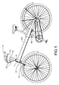
Fig. 1 , the present invention is adapted to a bike, a light-duty motorcycle or any other light-duty vehicle provided with both left and right brake levers to respectively control braking a front wheel and a rear wheel, and the bike is taken as an example for the purpose hereunder. As illustrated, the bike is provided with a right handlebar and aleft handlebar 91 respectively mounted with amanual brake lever 92; and abrake cable 93 connects bothbrake levers 92 to a safety braking system 1 of the present invention. The safety braking system 1 is mounted to ahead tube 96 or where between bothhandlebars 91, or coupled to astem 94 and connected to alead cable 951 and alead cable 952 respectively of afront wheel brake 941 and arear wheel brake 942. Accordingly, when either of both brake levers 92 is pulled, therear wheel brake 942 applies first a brake on the rear wheel and then thefront wheel 941 applies a brake on the front wheel. - In a first preferred embodiment of the safety braking system 1 of the present invention as illustrated in
Fig. 2 , the safety braking system 1 mounted to thehead tube 96 is comprised of twoarc levers pivoting point 30; twobrake cables 93 are connected to one side of both arc levers 10, 20 to form a primary mechanism. On the opposite side of thepivoting point 30 are respectively provided with tworollers - Now referring to
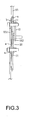
Fig. 3 , eachroller lead cable 952 of the rear wheel brake; and both smaller wheels b hold thelead cable 951 of the front wheel brake. - According to the operating status respectively illustrated in
Figs. 4 and5 , a distance between centers of bothrollers brake cable 93 connected to the brake lever is not yet pulled as illustrated inFig. 4 ; when thebrake cable 93 is pulled in a direction marked by an arrow G1 inFig. 5 , a braking force is created to move the primary mechanism comprised of both arc levers 10, 20. The primary mechanism transfers the braking force to the secondary power transmission mechanism, and the distance between both centers ofrollers lead cable 952 of the rear brake held by both larger wheels a of tworollers lead cable 951 of the front brake held by both smaller wheels b of tworollers rear wheel brake 942 will first brake the rear wheel before thefront wheel brake 941 applying a brake on the front wheel. - In another preferred embodiment of the present invention as illustrated in
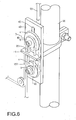
Figs. 6 and7 , asafety braking system 2 is disposed with a holdingbase 40 fixed to thehead tube 96; anupper roller 41 and alower roller 42 are provided on the holdingbase 40; thelower roller 42 may be provided as a stationary roller or a roller permitted to move downwardly; theupper roller 41 against thelower roller 42 displaces along a channel disposed on the holding base; and thebrake cable 93 of the brake lever is directly connected to theupper roller 42. When the brake lever is applied, thebrake cable 93 pulls theupper roller 42 to move upwardly. Each of both the upper and thelower rollers lead cable 952 of the rear brake and both smaller wheels b hold alead cable 951 of the front brake; and both leadcables cable holding frame 44. - According to an operating status respectively illustrated in
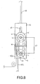
Figs. 8 and9 , a relative distance between both centers of the upper and thelower rollers Fig. 8 when abrake cable 93 connected to a brake lever is not yet pulled. When thebrake cable 93 is pulled in a direction marked by an arrow G4 as illustrated inFig. 9 , a braking force is created, theupper roller 41 moves upward for the relative distance between both centers of the upper and thelower rollers lead cables lead cable 952 of the rear brake held by both larger wheels a of tworollers lead cable 951 of the front brake held by both smaller wheels b of tworollers rear wheel brake 942 will first brake the rear wheel before thefront wheel brake 941 applying a brake on the front wheel. - Alternatively, the
safety braking system 2 of the present invention is mounted to at where appropriately between the right and theleft handlebars 91 or thestem 94 connecting both handlebars and the head tube; and thesafety braking system 2 may be mounted horizontally as illustrated inFig. 10 or vertically as illustrated inFig. 6 . - The brake cable of the brake lever may be connected to a rack, i.e., the primary mechanism; and a gear set connected to both rollers bits the rack. Each roller includes a larger wheel and a smaller wheel with each having a groove along its edge, and a distance between both centers of two rollers relatively increases when the brake cable pulls both rollers on the rack, a variable summary design of the present invention protected by a patent.
- According to another preferred embodiment yet of the present invention as illustrated in
Figs. 11 ,12 . Thesafety braking system 2 mounted to thehead tube 96 has twoarc levers pivoting point 30. One side of both arc levers 10, 20 is connected to abrake cable 93 of the brake lever to form a primary mechanism; on the opposite side of thepivoting point 30 are respectively provided with two rollers a, b, with each having a groove along its edge, to form a secondary power transmission mechanism. Both wheels a hold alead cable 952 of the rear wheel brake and another two wheels b hold alead cable 951 of the front wheel brake. As illustrated, when thebrake cable 93 connected to the brake lever is not pulled, a distance between both centers of two wheels a is designated as L5 and a distance between both centers of two wheels b, L6. When the brake lever is applied by a rider to pull he brakecable 93 in a direction marked G7 as illustrated inFig. 12 , a braking force is generated for the primary mechanism comprised of both arc levers to move for transferring the braking force to the secondary power transmission mechanism and both distances L5, L6 on the opposite side of both arc levers increase up to that respectively designated as L7 and L8. Meanwhile, both of thelead cable 952 of the rear brake held by both wheels a and thelead cable 951 of the front brake held by both wheels b create a pull force (as designated by arrows G8 and G9) for the secondary power transmission mechanism to respectively transfer the braking force to the front and the rear brakes; and therear wheel brake 942 will first brake the rear wheel before thefront wheel brake 941 applying a brake on the front wheel. In the preferred embodiment, a distance D1 between an axes of the wheel a and thepivoting point 30 is greater than D2, a distance between an axis of the wheel b and the pivoting point. According to the law of tangent of trigonometric function:


- Accordingly, when D 1 is greater than D2, the distance increased between two wheels a is greater than that between two wheels b. That is, amount of change in the length of the
lead cable 952 is greater than that of thelead cable 951, so that when both brake levers are pulled at the same time, the rear wheel brake operates first to brake. - Referring to
Figs. 13 and14 , a locating mechanism is disposed to both arc levers 10, 20 to allow both wheels a, b to adjust their positions on the arc levers as desired. As illustrated inFig. 13 ,multiple holes holes 101, 102 on both arc levers 10, 20 and those wheels each having a groove along its edge to secure both arc levers 10, 20 to those wheels. The locking member S may be related to a screw or a fast connector. Alternatively as illustrated inFigs. 14 and15 , a chute F and a slide V combined with and placed in the chute F are disposed on each of both arc levers. When a locking member S is released, the wheel slides in the chute F to reach a preset location, and the locking member S pulls closer the slide V to compress with those wheels on a wind F1 of the chute F so to locate the arc levers to those wheels. The locking member S may be related to a screw or a fast connector. With the locating mechanism, the rider may adjust the position of each wheel having a groove along its edge according to his/her particular riding behavior to achieve the optimal braking effects. - Now referring to
Fig. 16 , one wheel a and one wheel b on one arc lever are locked at a same point (concentrically) to achieve purpose of having the amount of change of thelead cable 952 become greater than that of thelead cable 951 thus to allow the rear wheel brake connected to thelead cable 952 to act first. Furthermore, as illustrated inFig. 17 , both ends respectively of thelead cable 951 and thelead cable 952 are directly fixed to thearc lever 20 to achieve the same purpose. The preferred embodiment illustrated inFigs. 16 and17 may be provided with the same locating mechanism as that mounted to the preferred embodiment illustrated inFigs. 13 ,14 , and15 to achieve the purpose of adjusting the position of each wheel having a groove along its edge on the arc levers. - The
safety braking system 2 of the present invention may be mounted to where appropriately between bothhandlebars 91, on thestem 94 that connects bothhandlebars 91 and the head tube vertically or horizontally. - It is to be noted that the preferred embodiments disclosed in the specification and the accompanying drawings are not limiting the present invention; and that any construction, installation, or characteristics that is same or similar to that of the present invention should fall within the scope of the purposes and claims of the present invention.
Claims (17)
- A safety braking system mounted to a bike, motorcycle or any other two-wheel linear type of vehicle adapted with a right and a left brake lever to respectively control applying a brake to a front wheel and a rear wheel of the vehicle, comprising a safety brake mounted to where between both brake levers and the front and the rear wheel brakes; and the safety braking system controls the rear wheel brake to apply the braking first and either brake lever and then controls the front wheel brake to apply the braking whenever either brake lever is pulled.
- The safety braking system as claimed in Claim 1, wherein the safety braking system comprising a primary mechanism and a secondary power transmission mechanism, both of the right and the left brake levers being connected to the primary mechanism; the primary mechanism transferring a braking force generated by either brake lever to the secondary power transmission mechanism; the braking force being further transferred to the front and the rear wheel brakes through the secondary power transmission mechanism; and the safety braking system controls to brake the rear wheel first before braking the front wheel.
- The safety braking system as claimed in Claim 2, wherein the secondary power transmission mechanism is related to a sheave comprised of two rollers; both rollers hold a lead cable from the front and the rear wheel brakes; both rollers move relative to each other when subject to the braking force applied by the brake lever to brake both front and rear wheels in sequence.
- The safety braking system as claimed in Claim 3, wherein each roller is comprised of a larger wheel and a smaller wheel each having a groove along its edge; the larger wheel holds a lead cable from the rear brake; and the smaller wheel holds a lead cable from the front brake.
- The safety braking system as claimed in Claim 1, wherein the safety braking system has two arc levers pivoted to each other at their centers as a pivoting point; one side of both arc levers being connected to a brake cable from the brake lever; on the opposite side of the pivoting point being respectively provided with two rollers; each roller each roller being comprised of a larger wheel and a smaller wheel each having a groove along its edge; and the larger wheel holding a lead cable from the rear brake; and the smaller wheel holding a lead cable from the front brake.
- The safety braking system as claimed in Claim 1, wherein the safety braking system is further comprised of a holding base; an upper roller and a lower roller being disposed on the holding base; the lower roller being stationary or allowed to more downward; the upper roller displacing along a channel disposed on the holding base; and the brake cable of the brake lever being directly connected to the upper roller; the brake cable pulling the upper roller to move upwardly when the brake lever is applied; each of the upper roller and the lower roller being disposed with a larger wheel and a smaller wheel with each having a groove along its edge; the larger wheel holding a lead cable from the rear brake; and the smaller wheel holding a lead cable from the front brake.
- The safety braking system as claimed in Claim 6, wherein two rollers are provided with each comprised of a larger roller and a smaller roller combined in a fashion that provides similar type of construction and efforts-saving features found with a conventional pulley, the rollers may be designed with various ratios between the larger and the smaller rollers depending on model and frame of the vehicle to adjust for a proper braking force and a ratio of braking force between that applied to the front and the rear wheel brakes.
- The safety braking system as claimed in Claim 6, wherein a lead cable holding frame is disposed to the holding base for both lead cables to penetrate through and to be secured on the holding frame.
- A safety braking system mounted to a bike, motorcycle or any other two-wheel linear type of vehicle adapted with a right and a left brake lever to respectively control applying a brake to a front wheel and a rear wheel of the vehicle, comprising a right brake lever, a left brake lever, a front wheel brake, a rear wheel brake, and a safety brake mounted to where between both brake levers and both wheel brakes; and the safety brake controls the front and the rear wheel brakes when either of both brake lever is pulled to measure of that the rear wheel brake brakes the rear wheel first before the front wheel brake brakes the front wheel.
- An improved construction of a safety braking system mounted to a bike, motorcycle or any other two-wheel linear type of vehicle adapted with a right and a left brake lever to respectively control applying a brake to a front wheel and a rear wheel of the vehicle comprising a safety brake mounted to where between both brake levers and both wheel brakes; wherein the safety brake controls the rear wheel brake to brake the rear wheel first before controlling the front wheel brake to brake the front wheel whenever either of both brake levers is pulled; the safety brake has two arc levers pivoted to each other at their centers as a pivoting point; one side of both arc levers is connected to brake cables from both brake levers; one a opposite side to the pivoting point are respectively disposed with two wheels each having a groove along its edge at each arc lever; those two wheels each having a groove along its edge that are farther from the pivoting point hold a lead cable from the rear wheel brake; and another two wheels each having a groove along its edge that are closer to the pivoting point hold a lead cable from the front wheel brake.
- An improved construction of a safety braking system mounted to a bike, motorcycle or any other two-wheel linear type of vehicle adapted with a right and a left brake lever to respectively control applying a brake to a front wheel and a rear wheel of the vehicle, wherein the safety brake has two arc levers pivoted to each other at their centers as a pivoting point; one side of both arc levers is connected to brake cables from both brake levers; two wheels with each having a groove along its edge are disposed on each of both arc levers on an opposite side to the pivoting point; and two wheels each having a groove along its edge on one arc lever are fixed to a same point on that arc lever and hold those lead cables with another two wheels each having a groove along its edge.
- An improved construction of a safety braking system mounted to a bike, motorcycle or any other two-wheel linear type of vehicle adapted with a right and a left brake lever to respectively control applying a brake to a front wheel and a rear wheel of the vehicle comprising a safety brake mounted to where between both brake levers, wherein when either brake lever is pulled, the safety brake controls the rear wheel brake to brake the rear wheel first before controlling the front wheel brake to brake the front wheel; the safety brake has two arc levers pivoted to each other at their centers as a pivoting point; one side of both arc levers is connected to brake cables from both brake levers; two wheels with each having a groove along its edge are disposed on an arc lever on an opposite side to the pivoting point; and those lead cables held by both wheels each having a groove along its edge are fixed to the other arc lever.
- The improved construction of a safety braking system as claimed in Claim 10, 11, or 12, wherein a locating mechanism is disposed to both arc levers to adjust the position of any of those wheels each having a groove along its edge.
- The improved construction of a safety braking system as claimed in Claim 13, wherein the locating mechanism contains multiple holes disposed on both arc levers and one or a plurality of locking member; and the locking member penetrates through selected holes on both arc levers and those wheels each having a groove along its edge to secure them in position.
- The improved construction of a safety braking system as claimed in Claim 14, wherein the locating mechanism is comprised of a slide disposed on both arc levers and a slider combined to and placed in the slide for those wheels each having a groove along its edge to move along the slide; and a retaining mechanism is disposed to secure the position of the wheel having a groove along its edge.
- The improved construction of a safety braking system as claimed in Claim 15, wherein the retaining mechanism contains a locking member penetrating the slider and those wheels with a groove along its edge.
- The improved construction of a safety braking system as claimed in Claim 15, wherein the locking member relates to a fast connector.
Priority Applications (2)
| Application Number | Priority Date | Filing Date | Title |
|---|---|---|---|
| ES07111804T ES2400526T3 (en) | 2007-07-05 | 2007-07-05 | Safety braking system |
| EP20070111804 EP2011730B1 (en) | 2007-07-05 | 2007-07-05 | Safety braking system |
Applications Claiming Priority (1)
| Application Number | Priority Date | Filing Date | Title |
|---|---|---|---|
| EP20070111804 EP2011730B1 (en) | 2007-07-05 | 2007-07-05 | Safety braking system |
Publications (2)
| Publication Number | Publication Date |
|---|---|
| EP2011730A1 true EP2011730A1 (en) | 2009-01-07 |
| EP2011730B1 EP2011730B1 (en) | 2012-11-28 |
Family
ID=38792728
Family Applications (1)
| Application Number | Title | Priority Date | Filing Date |
|---|---|---|---|
| EP20070111804 Not-in-force EP2011730B1 (en) | 2007-07-05 | 2007-07-05 | Safety braking system |
Country Status (2)
| Country | Link |
|---|---|
| EP (1) | EP2011730B1 (en) |
| ES (1) | ES2400526T3 (en) |
Cited By (1)
| Publication number | Priority date | Publication date | Assignee | Title |
|---|---|---|---|---|
| CN106494554A (en) * | 2016-11-16 | 2017-03-15 | 力帆实业(集团)股份有限公司 | A kind of motorcycle front and back linkage arrestment mechanism |
Citations (6)
| Publication number | Priority date | Publication date | Assignee | Title |
|---|---|---|---|---|
| FR907527A (en) * | 1944-10-27 | 1946-03-14 | Improvements to cycle brakes | |
| GB2175657A (en) * | 1985-05-07 | 1986-12-03 | Masataro Sato | A braking system for a bicycle |
| DE19951535A1 (en) * | 1998-10-26 | 2000-05-04 | Honda Motor Co Ltd | Braking arrangement for motor cycle has electronic controller that derives control signals for hydraulic actuators for actuating front and rear brakes from brake actuator sensor signals |
| EP1035009A2 (en) * | 1999-03-10 | 2000-09-13 | Chih-Chen Juan | Balanced braking system for a bicycle |
| US20030140724A1 (en) * | 2002-01-30 | 2003-07-31 | Sen-Yung Lee | Synchronous brake device |
| DE20309134U1 (en) * | 2003-06-12 | 2003-08-14 | Chun, Te Wen, Taichung | Synchronous balanced brake unit has rectangular housing with T-shaped opening in base for L-shaped slide plate which has arc-shaped slot and round hole for balance component which by screw is fastened on round hole |
-
2007
- 2007-07-05 ES ES07111804T patent/ES2400526T3/en active Active
- 2007-07-05 EP EP20070111804 patent/EP2011730B1/en not_active Not-in-force
Patent Citations (6)
| Publication number | Priority date | Publication date | Assignee | Title |
|---|---|---|---|---|
| FR907527A (en) * | 1944-10-27 | 1946-03-14 | Improvements to cycle brakes | |
| GB2175657A (en) * | 1985-05-07 | 1986-12-03 | Masataro Sato | A braking system for a bicycle |
| DE19951535A1 (en) * | 1998-10-26 | 2000-05-04 | Honda Motor Co Ltd | Braking arrangement for motor cycle has electronic controller that derives control signals for hydraulic actuators for actuating front and rear brakes from brake actuator sensor signals |
| EP1035009A2 (en) * | 1999-03-10 | 2000-09-13 | Chih-Chen Juan | Balanced braking system for a bicycle |
| US20030140724A1 (en) * | 2002-01-30 | 2003-07-31 | Sen-Yung Lee | Synchronous brake device |
| DE20309134U1 (en) * | 2003-06-12 | 2003-08-14 | Chun, Te Wen, Taichung | Synchronous balanced brake unit has rectangular housing with T-shaped opening in base for L-shaped slide plate which has arc-shaped slot and round hole for balance component which by screw is fastened on round hole |
Cited By (1)
| Publication number | Priority date | Publication date | Assignee | Title |
|---|---|---|---|---|
| CN106494554A (en) * | 2016-11-16 | 2017-03-15 | 力帆实业(集团)股份有限公司 | A kind of motorcycle front and back linkage arrestment mechanism |
Also Published As
| Publication number | Publication date |
|---|---|
| EP2011730B1 (en) | 2012-11-28 |
| ES2400526T3 (en) | 2013-04-10 |
Similar Documents
| Publication | Publication Date | Title |
|---|---|---|
| US5845539A (en) | Braking lever assembly for synchronically actuating braking mechanisms | |
| EP1035009B1 (en) | Balanced braking system for a bicycle | |
| US20100230214A1 (en) | Safe Braking Apparatus | |
| US6311805B1 (en) | Balanced braking system for a bicycle | |
| US8136638B2 (en) | Safety braking system | |
| US9180928B2 (en) | Brake system with linking effect | |
| US6725978B2 (en) | Cable joining system for cycles | |
| US8794391B2 (en) | Safety braking system | |
| EP2687432A1 (en) | Two-position control device | |
| JP2009012660A (en) | Safety braking unit | |
| EP2011730B1 (en) | Safety braking system | |
| CN101229836B (en) | Safety brake | |
| US20040079186A1 (en) | Automatic brake system modulator | |
| WO2016108247A1 (en) | Synchronized braking system | |
| EP2639123B1 (en) | Brake auxiliary device | |
| US9493146B1 (en) | Brake-aiding device | |
| CN103707987B (en) | Time difference safety brake device | |
| US10532790B2 (en) | Control device for a bicycle | |
| KR20180013347A (en) | Roller Sled | |
| CN101337545A (en) | Anti-lock and anti-skid mechanical torque braking system and method for bicycles and motor vehicles | |
| EP2857303B1 (en) | Time difference safety brake | |
| EP3127798B1 (en) | Brake-aiding device | |
| DE4340479A1 (en) | Ski kit for mounting on muscle or motor-powered two-wheeled vehicles | |
| JP3088784U (en) | Safe simultaneous braking system with adjustable braking force | |
| DE60112814T2 (en) | CROSS-DRIVEN ICE VEHICLE |
Legal Events
| Date | Code | Title | Description |
|---|---|---|---|
| PUAI | Public reference made under article 153(3) epc to a published international application that has entered the european phase |
Free format text: ORIGINAL CODE: 0009012 |
|
| AK | Designated contracting states |
Kind code of ref document: A1 Designated state(s): AT BE BG CH CY CZ DE DK EE ES FI FR GB GR HU IE IS IT LI LT LU LV MC MT NL PL PT RO SE SI SK TR |
|
| AX | Request for extension of the european patent |
Extension state: AL BA HR MK RS |
|
| 17P | Request for examination filed |
Effective date: 20090626 |
|
| 17Q | First examination report despatched |
Effective date: 20090729 |
|
| AKX | Designation fees paid |
Designated state(s): AT BE BG CH CY CZ DE DK EE ES FI FR GB GR HU IE IS IT LI LT LU LV MC MT NL PL PT RO SE SI SK TR |
|
| GRAP | Despatch of communication of intention to grant a patent |
Free format text: ORIGINAL CODE: EPIDOSNIGR1 |
|
| GRAS | Grant fee paid |
Free format text: ORIGINAL CODE: EPIDOSNIGR3 |
|
| GRAA | (expected) grant |
Free format text: ORIGINAL CODE: 0009210 |
|
| AK | Designated contracting states |
Kind code of ref document: B1 Designated state(s): AT BE BG CH CY CZ DE DK EE ES FI FR GB GR HU IE IS IT LI LT LU LV MC MT NL PL PT RO SE SI SK TR |
|
| REG | Reference to a national code |
Ref country code: GB Ref legal event code: FG4D |
|
| REG | Reference to a national code |
Ref country code: CH Ref legal event code: EP |
|
| REG | Reference to a national code |
Ref country code: AT Ref legal event code: REF Ref document number: 586012 Country of ref document: AT Kind code of ref document: T Effective date: 20121215 |
|
| REG | Reference to a national code |
Ref country code: IE Ref legal event code: FG4D |
|
| REG | Reference to a national code |
Ref country code: DE Ref legal event code: R096 Ref document number: 602007026952 Country of ref document: DE Effective date: 20130124 |
|
| REG | Reference to a national code |
Ref country code: SE Ref legal event code: TRGR |
|
| REG | Reference to a national code |
Ref country code: NL Ref legal event code: T3 |
|
| REG | Reference to a national code |
Ref country code: ES Ref legal event code: FG2A Ref document number: 2400526 Country of ref document: ES Kind code of ref document: T3 Effective date: 20130410 |
|
| REG | Reference to a national code |
Ref country code: AT Ref legal event code: MK05 Ref document number: 586012 Country of ref document: AT Kind code of ref document: T Effective date: 20121128 |
|
| REG | Reference to a national code |
Ref country code: LT Ref legal event code: MG4D |
|
| PG25 | Lapsed in a contracting state [announced via postgrant information from national office to epo] |
Ref country code: LT Free format text: LAPSE BECAUSE OF FAILURE TO SUBMIT A TRANSLATION OF THE DESCRIPTION OR TO PAY THE FEE WITHIN THE PRESCRIBED TIME-LIMIT Effective date: 20121128 |
|
| PG25 | Lapsed in a contracting state [announced via postgrant information from national office to epo] |
Ref country code: PL Free format text: LAPSE BECAUSE OF FAILURE TO SUBMIT A TRANSLATION OF THE DESCRIPTION OR TO PAY THE FEE WITHIN THE PRESCRIBED TIME-LIMIT Effective date: 20121128 Ref country code: GR Free format text: LAPSE BECAUSE OF FAILURE TO SUBMIT A TRANSLATION OF THE DESCRIPTION OR TO PAY THE FEE WITHIN THE PRESCRIBED TIME-LIMIT Effective date: 20130301 Ref country code: CY Free format text: LAPSE BECAUSE OF FAILURE TO SUBMIT A TRANSLATION OF THE DESCRIPTION OR TO PAY THE FEE WITHIN THE PRESCRIBED TIME-LIMIT Effective date: 20121128 Ref country code: LV Free format text: LAPSE BECAUSE OF FAILURE TO SUBMIT A TRANSLATION OF THE DESCRIPTION OR TO PAY THE FEE WITHIN THE PRESCRIBED TIME-LIMIT Effective date: 20121128 Ref country code: PT Free format text: LAPSE BECAUSE OF FAILURE TO SUBMIT A TRANSLATION OF THE DESCRIPTION OR TO PAY THE FEE WITHIN THE PRESCRIBED TIME-LIMIT Effective date: 20130328 Ref country code: BE Free format text: LAPSE BECAUSE OF FAILURE TO SUBMIT A TRANSLATION OF THE DESCRIPTION OR TO PAY THE FEE WITHIN THE PRESCRIBED TIME-LIMIT Effective date: 20121128 Ref country code: SI Free format text: LAPSE BECAUSE OF FAILURE TO SUBMIT A TRANSLATION OF THE DESCRIPTION OR TO PAY THE FEE WITHIN THE PRESCRIBED TIME-LIMIT Effective date: 20121128 |
|
| PG25 | Lapsed in a contracting state [announced via postgrant information from national office to epo] |
Ref country code: AT Free format text: LAPSE BECAUSE OF FAILURE TO SUBMIT A TRANSLATION OF THE DESCRIPTION OR TO PAY THE FEE WITHIN THE PRESCRIBED TIME-LIMIT Effective date: 20121128 |
|
| PG25 | Lapsed in a contracting state [announced via postgrant information from national office to epo] |
Ref country code: EE Free format text: LAPSE BECAUSE OF FAILURE TO SUBMIT A TRANSLATION OF THE DESCRIPTION OR TO PAY THE FEE WITHIN THE PRESCRIBED TIME-LIMIT Effective date: 20121128 Ref country code: BG Free format text: LAPSE BECAUSE OF FAILURE TO SUBMIT A TRANSLATION OF THE DESCRIPTION OR TO PAY THE FEE WITHIN THE PRESCRIBED TIME-LIMIT Effective date: 20130228 Ref country code: CZ Free format text: LAPSE BECAUSE OF FAILURE TO SUBMIT A TRANSLATION OF THE DESCRIPTION OR TO PAY THE FEE WITHIN THE PRESCRIBED TIME-LIMIT Effective date: 20121128 Ref country code: SK Free format text: LAPSE BECAUSE OF FAILURE TO SUBMIT A TRANSLATION OF THE DESCRIPTION OR TO PAY THE FEE WITHIN THE PRESCRIBED TIME-LIMIT Effective date: 20121128 Ref country code: DK Free format text: LAPSE BECAUSE OF FAILURE TO SUBMIT A TRANSLATION OF THE DESCRIPTION OR TO PAY THE FEE WITHIN THE PRESCRIBED TIME-LIMIT Effective date: 20121128 |
|
| PG25 | Lapsed in a contracting state [announced via postgrant information from national office to epo] |
Ref country code: RO Free format text: LAPSE BECAUSE OF FAILURE TO SUBMIT A TRANSLATION OF THE DESCRIPTION OR TO PAY THE FEE WITHIN THE PRESCRIBED TIME-LIMIT Effective date: 20121128 |
|
| PLBE | No opposition filed within time limit |
Free format text: ORIGINAL CODE: 0009261 |
|
| STAA | Information on the status of an ep patent application or granted ep patent |
Free format text: STATUS: NO OPPOSITION FILED WITHIN TIME LIMIT |
|
| 26N | No opposition filed |
Effective date: 20130829 |
|
| REG | Reference to a national code |
Ref country code: DE Ref legal event code: R097 Ref document number: 602007026952 Country of ref document: DE Effective date: 20130829 |
|
| REG | Reference to a national code |
Ref country code: IE Ref legal event code: MM4A |
|
| PG25 | Lapsed in a contracting state [announced via postgrant information from national office to epo] |
Ref country code: IE Free format text: LAPSE BECAUSE OF NON-PAYMENT OF DUE FEES Effective date: 20130705 |
|
| PG25 | Lapsed in a contracting state [announced via postgrant information from national office to epo] |
Ref country code: MT Free format text: LAPSE BECAUSE OF FAILURE TO SUBMIT A TRANSLATION OF THE DESCRIPTION OR TO PAY THE FEE WITHIN THE PRESCRIBED TIME-LIMIT Effective date: 20121128 Ref country code: TR Free format text: LAPSE BECAUSE OF FAILURE TO SUBMIT A TRANSLATION OF THE DESCRIPTION OR TO PAY THE FEE WITHIN THE PRESCRIBED TIME-LIMIT Effective date: 20121128 |
|
| PG25 | Lapsed in a contracting state [announced via postgrant information from national office to epo] |
Ref country code: HU Free format text: LAPSE BECAUSE OF FAILURE TO SUBMIT A TRANSLATION OF THE DESCRIPTION OR TO PAY THE FEE WITHIN THE PRESCRIBED TIME-LIMIT; INVALID AB INITIO Effective date: 20070705 |
|
| PG25 | Lapsed in a contracting state [announced via postgrant information from national office to epo] |
Ref country code: IS Free format text: LAPSE BECAUSE OF FAILURE TO SUBMIT A TRANSLATION OF THE DESCRIPTION OR TO PAY THE FEE WITHIN THE PRESCRIBED TIME-LIMIT Effective date: 20121128 |
|
| REG | Reference to a national code |
Ref country code: FR Ref legal event code: PLFP Year of fee payment: 10 |
|
| PGFP | Annual fee paid to national office [announced via postgrant information from national office to epo] |
Ref country code: LU Payment date: 20160726 Year of fee payment: 10 |
|
| PGFP | Annual fee paid to national office [announced via postgrant information from national office to epo] |
Ref country code: NL Payment date: 20160630 Year of fee payment: 10 |
|
| PGFP | Annual fee paid to national office [announced via postgrant information from national office to epo] |
Ref country code: MC Payment date: 20160714 Year of fee payment: 10 Ref country code: GB Payment date: 20160725 Year of fee payment: 10 Ref country code: FI Payment date: 20160718 Year of fee payment: 10 Ref country code: DE Payment date: 20160721 Year of fee payment: 10 Ref country code: CH Payment date: 20160721 Year of fee payment: 10 Ref country code: IT Payment date: 20160628 Year of fee payment: 10 |
|
| PGFP | Annual fee paid to national office [announced via postgrant information from national office to epo] |
Ref country code: FR Payment date: 20160722 Year of fee payment: 10 Ref country code: SE Payment date: 20160713 Year of fee payment: 10 |
|
| PGFP | Annual fee paid to national office [announced via postgrant information from national office to epo] |
Ref country code: ES Payment date: 20160817 Year of fee payment: 10 |
|
| REG | Reference to a national code |
Ref country code: DE Ref legal event code: R119 Ref document number: 602007026952 Country of ref document: DE |
|
| REG | Reference to a national code |
Ref country code: CH Ref legal event code: PL |
|
| REG | Reference to a national code |
Ref country code: NL Ref legal event code: MM Effective date: 20170801 |
|
| REG | Reference to a national code |
Ref country code: SE Ref legal event code: EUG |
|
| GBPC | Gb: european patent ceased through non-payment of renewal fee |
Effective date: 20170705 |
|
| REG | Reference to a national code |
Ref country code: FR Ref legal event code: ST Effective date: 20180330 |
|
| PG25 | Lapsed in a contracting state [announced via postgrant information from national office to epo] |
Ref country code: GB Free format text: LAPSE BECAUSE OF NON-PAYMENT OF DUE FEES Effective date: 20170705 Ref country code: DE Free format text: LAPSE BECAUSE OF NON-PAYMENT OF DUE FEES Effective date: 20180201 Ref country code: SE Free format text: LAPSE BECAUSE OF NON-PAYMENT OF DUE FEES Effective date: 20170706 Ref country code: CH Free format text: LAPSE BECAUSE OF NON-PAYMENT OF DUE FEES Effective date: 20170731 Ref country code: NL Free format text: LAPSE BECAUSE OF NON-PAYMENT OF DUE FEES Effective date: 20170801 Ref country code: FI Free format text: LAPSE BECAUSE OF NON-PAYMENT OF DUE FEES Effective date: 20170705 Ref country code: LI Free format text: LAPSE BECAUSE OF NON-PAYMENT OF DUE FEES Effective date: 20170731 |
|
| PG25 | Lapsed in a contracting state [announced via postgrant information from national office to epo] |
Ref country code: FR Free format text: LAPSE BECAUSE OF NON-PAYMENT OF DUE FEES Effective date: 20170731 |
|
| PG25 | Lapsed in a contracting state [announced via postgrant information from national office to epo] |
Ref country code: LU Free format text: LAPSE BECAUSE OF NON-PAYMENT OF DUE FEES Effective date: 20170705 |
|
| PG25 | Lapsed in a contracting state [announced via postgrant information from national office to epo] |
Ref country code: IT Free format text: LAPSE BECAUSE OF NON-PAYMENT OF DUE FEES Effective date: 20170705 |
|
| REG | Reference to a national code |
Ref country code: ES Ref legal event code: FD2A Effective date: 20181112 |
|
| PG25 | Lapsed in a contracting state [announced via postgrant information from national office to epo] |
Ref country code: ES Free format text: LAPSE BECAUSE OF NON-PAYMENT OF DUE FEES Effective date: 20170706 |
|
| PG25 | Lapsed in a contracting state [announced via postgrant information from national office to epo] |
Ref country code: MC Free format text: LAPSE BECAUSE OF NON-PAYMENT OF DUE FEES Effective date: 20170731 |