EP2011427A1 - Floor wiper for floor cleansing and drying machines - Google Patents
Floor wiper for floor cleansing and drying machines Download PDFInfo
- Publication number
- EP2011427A1 EP2011427A1 EP07425406A EP07425406A EP2011427A1 EP 2011427 A1 EP2011427 A1 EP 2011427A1 EP 07425406 A EP07425406 A EP 07425406A EP 07425406 A EP07425406 A EP 07425406A EP 2011427 A1 EP2011427 A1 EP 2011427A1
- Authority
- EP
- European Patent Office
- Prior art keywords
- floor
- wiper according
- floor wiper
- supporting body
- engagement
- Prior art date
- Legal status (The legal status is an assumption and is not a legal conclusion. Google has not performed a legal analysis and makes no representation as to the accuracy of the status listed.)
- Withdrawn
Links
Images


Classifications
-
- A—HUMAN NECESSITIES
- A47—FURNITURE; DOMESTIC ARTICLES OR APPLIANCES; COFFEE MILLS; SPICE MILLS; SUCTION CLEANERS IN GENERAL
- A47L—DOMESTIC WASHING OR CLEANING; SUCTION CLEANERS IN GENERAL
- A47L11/00—Machines for cleaning floors, carpets, furniture, walls, or wall coverings
- A47L11/40—Parts or details of machines not provided for in groups A47L11/02 - A47L11/38, or not restricted to one of these groups, e.g. handles, arrangements of switches, skirts, buffers, levers
- A47L11/4036—Parts or details of the surface treating tools
- A47L11/4044—Vacuuming or pick-up tools; Squeegees
-
- A—HUMAN NECESSITIES
- A47—FURNITURE; DOMESTIC ARTICLES OR APPLIANCES; COFFEE MILLS; SPICE MILLS; SUCTION CLEANERS IN GENERAL
- A47L—DOMESTIC WASHING OR CLEANING; SUCTION CLEANERS IN GENERAL
- A47L13/00—Implements for cleaning floors, carpets, furniture, walls, or wall coverings
- A47L13/10—Scrubbing; Scouring; Cleaning; Polishing
- A47L13/11—Squeegees
Definitions
- the present invention relates to a floor wiper for floor cleansing and drying machines.
- floor cleansing and drying machines are generally equipped with a floor wiper, which is arranged to the rear, along the direction of travel of the machine during use, with respect to the rotating brushes and the nozzles for dispensing the washing liquid.
- the floor wiper is designed to engage by contact the surface of the floor, so as to retain the washing liquid and the dirt that has been removed, thus allowing their collection by a suction port which dries the floor.
- the floor wiper is provided with a lip-shaped brush which is usually obtained by means of a strip of elastically yielding material, such as rubber or others, which is arranged substantially transversely to the travel direction of the machine and is supported by a supporting structure which is associated with the chassis of the machine.
- a lip-shaped brush which is usually obtained by means of a strip of elastically yielding material, such as rubber or others, which is arranged substantially transversely to the travel direction of the machine and is supported by a supporting structure which is associated with the chassis of the machine.
- Such supporting structure generally can be moved with respect to the chassis of the machine so as to allow the floor wiper to pass from a raised position, in which its brush is spaced upwardly from the floor, to a lowered position, in which the brush is pressed elastically, with its lower edge, against the floor to be cleaned, so as to be able to slide thereon during use of the machine, and vice versa.
- the floor wiper is connected detachably to the supporting structure by fixing means, which are constituted by threaded elements which can be clamped by means of wing nuts or the like to allow stable coupling between the floor wiper and the supporting structure.
- the aim of the present invention is to provide a solution to the drawbacks of the background art, by providing a floor wiper for floor cleansing and drying machines which can be fitted and removed with respect to the chassis of the machine with a small number of intuitive operations to clean it and maintain it without difficulties.
- An object of the present invention is to provide a floor wiper for floor cleansing and drying machines which can be connected securely to the machine chassis despite being easily removable from such machine.
- Another object of the present invention is to provide a floor wiper for floor cleansing and drying machines which is constructively simple to provide and has a low cost.
- the floor wiper according to the invention comprises a brush 2 which is supported by a supporting structure 3, which is connected to the chassis of a floor cleansing and drying machine, not shown for the sake of simplicity, and is designed to make sliding contact by way of its lower edge 2a with the floor to be cleaned during use of the floor cleansing and drying machine.
- the brush 2 is associated with a supporting body 4, which can be coupled detachably to the supporting structure 3 by snap-acting quick coupling means.
- such snap-acting quick coupling means comprise at least one male element, which is associated with the supporting body 4 and can engage in a female seat 5 which is provided in the supporting structure 3, and removable locking means, which are designed to engage the male element to lock it in the female seat 5 when the male element is inserted in the female seat 5.
- the male element is constituted conveniently by at least two mating pins 6, which are fixed to the supporting body 4 and can be inserted axially in corresponding female seats 5 provided in the supporting structure 3.
- such removable locking means comprise, for each mating pin 6, an engagement element 7, which is supported by the supporting structure 3 and has a locking head 7a which can engage a retention region 6a formed on the corresponding mating pin 6.
- Each engagement element 7 can move on command from an engagement position, in which it is engaged, with its locking head 7a, with the retention region 6a of the corresponding mating pin 6, so as to lock it in the corresponding female seat 5, to a disengagement position, in which it disengages from the retention region 6a of the corresponding mating pin 6 to allow the axial extraction of the latter from the corresponding female seat 5, and vice versa.
- each engagement element 7 is advantageously pivoted, with an intermediate portion, to the supporting structure 3 about an oscillation axis which is substantially parallel to the insertion direction of the corresponding mating pin 6 in the corresponding female seat 5.
- each engagement element 7 can move from the engagement position to the disengagement position in contrast with the action of elastic return means, which are constituted for example by a helical spring 8 which is interposed between the engagement element 7 and the supporting structure 3.
- the helical spring 8 in practice pushes the engagement head 7a of the engagement element 7 against the lateral surface of the corresponding mating pin 6 when the latter is inserted in the corresponding female seat 5.
- each engagement element 7 is provided, on the opposite side with respect to the locking head 7a, with an actuation portion 7b, on which it is possible to act manually to disengage the engagement element 7 from the corresponding mating pin 6, causing the passage of the engagement element 7 from the engagement position to the disengagement position.
- each mating pin 6 comprises an axial shoulder 9, which is directed away from the end of the mating pin 6 which can be inserted in the corresponding female seat 5 and can be engaged by abutment by the locking head 7a of the corresponding engagement element 7, in order to prevent axial extraction of the mating pin 6 from the corresponding female seat 5.
- the axial shoulder 9 is formed, at least partially, by a circumferential groove 10 provided on the outer lateral surface of each mating pin 6.
- the locking head 7a of each engagement element 7 is conveniently shaped complementarily with respect to the corresponding circumferential groove 10.
- each mating pin 6 further comprises a toothed protrusion 11, which protrudes from the lateral surface of the corresponding mating pin 6 and conveniently has an annular shape arranged around the axis of such mating pin.
- the toothed protrusion 11 is adapted with a front side 11a which is directed toward the end of the mating pin 6 which can be inserted in the corresponding female seat 5, which is shaped like an inclined plane with respect to the axis of the mating pin, and with an opposite abutment side 11b, which is substantially perpendicular to the axis of the mating pin 6.
- the front side 11a of the toothed protrusion 11 is adapted to engage by sliding with the locking head 7a of the corresponding engagement element 7 during the insertion of the mating pin 6 in the corresponding female seat 5, while the opposite abutment side 11b defines substantially at least one portion of the axial shoulder 9.
- the front side 11 a allows the toothed protrusion 11 to move beyond the locking head 7a of the engagement element 7, causing a rotation of the engagement element 7 about its own oscillation axis in contrast with the action of the helical spring 8, which immediately thereafter causes the engagement of the locking head with the opposite abutment side 11b of the toothed protrusion 11, thus achieving the automatic snap locking of the mating pin 6 in the corresponding female seat 5.
- the supporting structure 3 comprises a bar 12 which preferably has a flattened shape and is designed to be arranged substantially transversely to the advancement direction of the floor cleansing and drying machine.
- the female seats 5 are provided through the thickness of respective plate-like portions 13, which are associated with the bar 12, and their access opening is located at a face of the plate-like portions 13 which is directed toward the floor and therefore downwardly, so that the mating pins 6 can be inserted in the female seats 5 with an upward axial movement.
- the engagement elements 7 are advantageously pivoted on the opposite face of the plate-like portions 13.
- the bar 12 is conveniently provided with an abutment portion 14, which defines an engagement region for movement elements which are associated with the floor cleansing and drying machine and can be actuated to lift or lower the supporting structure 3 with respect to the floor, so as to be able to move the brush 2 into contact with the floor or disengage it from said floor.
- the abutment portion 14 is located advantageously in a central position of the longitudinal extension of the bar 12 and is constituted for example by a fork 15, which is fixed to the bar 12 and supports a roller 16 between its arms.
- the roller 16 is designed to engage the movement elements, which comprise for example a lifting lever 17, which passes through the fork 15 and can be actuated on command so as to rotate about an axis which is substantially parallel to the floor in order to engage the roller 16 and lift the supporting structure 3.
- the movement elements comprise for example a lifting lever 17, which passes through the fork 15 and can be actuated on command so as to rotate about an axis which is substantially parallel to the floor in order to engage the roller 16 and lift the supporting structure 3.
- the female seats 5 are arranged symmetrically, on mutually opposite sides, with respect to the abutment portion.
- the supporting body 4 preferably has a shape which is elongated substantially transversely to the advancement direction of the floor cleansing and drying machine during its use and conveniently lies along a circular arc whose concavity is directed along the advancement direction of the floor cleansing and drying machine in order to allow effective collection of the washing liquid by the brush 2.
- the brush 2 is provided by means of a strip 18 made of elastically yielding material, which is connected detachably to the supporting body 4.
- a plurality of teeth 19 are provided on the supporting body 4 and are mutually spaced along the longitudinal extension of the supporting body; such teeth can engage detachably within corresponding slots 20 provided in the strip 18.
- the locking of the strip 18 to the supporting body 4 is achieved by means of at least one pair of band-like fixing elements 21a and 21b, which are designed to face the strip 18 and can engage the supporting body 4 at one of their ends.
- the band-like fixing elements 21a and 21b can be mutually connected by means of a closure device 22, which is adapted to pull the band-like fixing elements 21a and 21b toward each other, so as to allow to lock the strip 18 between the band-like fixing elements 21a and 21b and an abutment surface 4a defined by the supporting body 4.
- the closure device 22 is constituted by a lever 24, which is pivoted to a base 25 which is fixed to one of the band-like fixing elements, which in the example shown in the figures is the one designated by the reference numeral 21b, and by a tension element 26, which is articulated, at one end, to the other band-like fixing element, i.e., the one designated by the reference numeral 21a in the figures, and engages rotatably on said pivot of the lever 24 so that by way of the oscillation of the lever 24 it is possible to apply a clamping action to the band-like fixing elements 21a, 21b.
- the strip 18 conveniently has, proximate to its longitudinal ends, two openings 27 which can be crossed by engagement tabs 28 provided at the ends of the band-like fixing elements 21a, 21b which lie opposite the ones which are connected by the closure device 22 and can engage detachably the supporting body 4.
- the band-like fixing elements 21a, 21b further have slots 23 for engagement with the teeth 19.
- at least the teeth located proximate to the longitudinal ends of the supporting body 4 preferably have a protrusion 19a which is directed away from the closure device 22 and defines an undercut region 29 with respect to a movement in the opposite direction with respect to the supporting body 4, said region being engageable by the edges of the corresponding slot 23, so as to provide a stable coupling between the band-like fixing elements 21a and 21b and the supporting body 4.
- the supporting body 4 is further provided with an intake port 30, which can be connected through a duct to a suction device, of any known type, which is associated with the floor cleansing and drying machine.
- the intake port 30 is connected to a suction chamber 31, which is open toward the floor and is defined between the strip 18 and a longitudinal delimiting wall 32 defined by the supporting body 4.
- the strip 18 is mated with the supporting body 4.
- the strip 18 is first rested against the abutment surface 4a of the supporting body 4, engaging the teeth 19 in the slots 20 of the strip 18, and is then fixed to the supporting body 4, engaging the engagement tabs 28 of the band-like fixing elements 21a, 2 1 b with the supporting body 4 and moving mutually closer the ends of the band-like fixing elements 21a, 21 b which lie opposite the engagement tabs 28 by acting on the lever 24 of the closure device 22, so as to lock the strip 18 against the abutment surface 4a of the supporting body 4.
- the supporting body 4 with the strip 18 thus coupled can be engaged with the supporting structure 3 by simply inserting the mating pins 6 in the respective female seats 5 and pushing the mating pins 6 enough to allow the toothed protrusion 11 to move beyond the locking head 7a of the engagement elements 7, which by way of the action of their return spring 8 can then move automatically to a position for engagement with the circumferential groove 10 of the mating pins 6, thus locking the mating pins 6 in the female seats 5.
- the supporting structure 3 in order to facilitate the insertion of the mating pins 6 in the female seats 5, it is preferable to arrange the supporting structure 3 in a position which is raised from the floor by way of the actuation of the lifting lever 17.
- the lifting lever 17 can be actuated so as to lower the supporting structure 3 and thus move the edge 2a of the brush 2 into contact with the floor.
- a floor wiper is provided which can be fitted to, or removed from, the floor cleansing and drying machine and disassembled into its components subject to replacement with operations which are extremely simple and very practical to perform.
- the materials used, as well as the contingent shapes and dimensions may be any according to requirements.
Landscapes
- Brushes (AREA)
Abstract
Description
- The present invention relates to a floor wiper for floor cleansing and drying machines.
- As is known, floor cleansing and drying machines are generally equipped with a floor wiper, which is arranged to the rear, along the direction of travel of the machine during use, with respect to the rotating brushes and the nozzles for dispensing the washing liquid.
- The floor wiper is designed to engage by contact the surface of the floor, so as to retain the washing liquid and the dirt that has been removed, thus allowing their collection by a suction port which dries the floor.
- Typically, the floor wiper is provided with a lip-shaped brush which is usually obtained by means of a strip of elastically yielding material, such as rubber or others, which is arranged substantially transversely to the travel direction of the machine and is supported by a supporting structure which is associated with the chassis of the machine.
- Such supporting structure generally can be moved with respect to the chassis of the machine so as to allow the floor wiper to pass from a raised position, in which its brush is spaced upwardly from the floor, to a lowered position, in which the brush is pressed elastically, with its lower edge, against the floor to be cleaned, so as to be able to slide thereon during use of the machine, and vice versa.
- To allow convenient washing of the floor wiper and any replacement of the brush once it has become worn, the floor wiper is connected detachably to the supporting structure by fixing means, which are constituted by threaded elements which can be clamped by means of wing nuts or the like to allow stable coupling between the floor wiper and the supporting structure.
- However, this solution proves to be scarcely practical, since to fit and remove the floor wiper to and from the supporting structure it is necessary to act on the threaded elements each time.
- The aim of the present invention is to provide a solution to the drawbacks of the background art, by providing a floor wiper for floor cleansing and drying machines which can be fitted and removed with respect to the chassis of the machine with a small number of intuitive operations to clean it and maintain it without difficulties.
- An object of the present invention is to provide a floor wiper for floor cleansing and drying machines which can be connected securely to the machine chassis despite being easily removable from such machine.
- Another object of the present invention is to provide a floor wiper for floor cleansing and drying machines which is constructively simple to provide and has a low cost.
- This aim and these and other objects which will become better apparent hereinafter are achieved by a floor wiper according to the invention, as defined in
claim 1. - Further characteristics and advantages of the invention will become better apparent from the description of a preferred but not exclusive embodiment of the floor wiper according to the invention, illustrated by way of non-limiting example in the accompanying drawings, wherein:
-
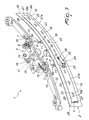
Figure 1 is a top plan view of the floor wiper according to the invention; -
Figure 2 is a perspective view of the floor wiper according to the invention; -
Figure 3 is a perspective view of the floor wiper according to the invention during assembly; -
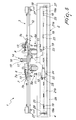
Figure 4 is a front elevation view of the floor wiper according to the invention; -
Figure 5 is a front elevation view of the floor wiper according to the invention during assembly; -
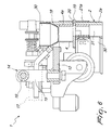
Figure 6 is a sectional view, taken along the line VI-VI ofFigure 1 ; -
Figure 7 is a sectional view, taken along the line VII-VII ofFigure 1 . - With reference to the figures, the floor wiper according to the invention, generally designated by the
reference numeral 1, comprises abrush 2 which is supported by a supportingstructure 3, which is connected to the chassis of a floor cleansing and drying machine, not shown for the sake of simplicity, and is designed to make sliding contact by way of itslower edge 2a with the floor to be cleaned during use of the floor cleansing and drying machine. - According to the invention, the
brush 2 is associated with a supportingbody 4, which can be coupled detachably to the supportingstructure 3 by snap-acting quick coupling means. - Advantageously, such snap-acting quick coupling means comprise at least one male element, which is associated with the supporting
body 4 and can engage in afemale seat 5 which is provided in the supportingstructure 3, and removable locking means, which are designed to engage the male element to lock it in thefemale seat 5 when the male element is inserted in thefemale seat 5. - As shown, the male element is constituted conveniently by at least two
mating pins 6, which are fixed to the supportingbody 4 and can be inserted axially in correspondingfemale seats 5 provided in the supportingstructure 3. - Advantageously, such removable locking means comprise, for each
mating pin 6, anengagement element 7, which is supported by the supportingstructure 3 and has alocking head 7a which can engage aretention region 6a formed on thecorresponding mating pin 6. - Each
engagement element 7 can move on command from an engagement position, in which it is engaged, with itslocking head 7a, with theretention region 6a of thecorresponding mating pin 6, so as to lock it in the correspondingfemale seat 5, to a disengagement position, in which it disengages from theretention region 6a of thecorresponding mating pin 6 to allow the axial extraction of the latter from the correspondingfemale seat 5, and vice versa. - More particularly, each
engagement element 7 is advantageously pivoted, with an intermediate portion, to the supportingstructure 3 about an oscillation axis which is substantially parallel to the insertion direction of thecorresponding mating pin 6 in the correspondingfemale seat 5. - Conveniently, each
engagement element 7 can move from the engagement position to the disengagement position in contrast with the action of elastic return means, which are constituted for example by ahelical spring 8 which is interposed between theengagement element 7 and the supportingstructure 3. Thehelical spring 8 in practice pushes theengagement head 7a of theengagement element 7 against the lateral surface of thecorresponding mating pin 6 when the latter is inserted in the correspondingfemale seat 5. - Advantageously, each
engagement element 7 is provided, on the opposite side with respect to thelocking head 7a, with anactuation portion 7b, on which it is possible to act manually to disengage theengagement element 7 from thecorresponding mating pin 6, causing the passage of theengagement element 7 from the engagement position to the disengagement position. - Conveniently, the
retention region 6a of eachmating pin 6 comprises anaxial shoulder 9, which is directed away from the end of themating pin 6 which can be inserted in the correspondingfemale seat 5 and can be engaged by abutment by thelocking head 7a of thecorresponding engagement element 7, in order to prevent axial extraction of themating pin 6 from the correspondingfemale seat 5. - Advantageously, the
axial shoulder 9 is formed, at least partially, by acircumferential groove 10 provided on the outer lateral surface of eachmating pin 6. Thelocking head 7a of eachengagement element 7 is conveniently shaped complementarily with respect to the correspondingcircumferential groove 10. - Preferably, the
retention region 6a of eachmating pin 6 further comprises atoothed protrusion 11, which protrudes from the lateral surface of thecorresponding mating pin 6 and conveniently has an annular shape arranged around the axis of such mating pin. - In particular, the
toothed protrusion 11 is adapted with afront side 11a which is directed toward the end of themating pin 6 which can be inserted in the correspondingfemale seat 5, which is shaped like an inclined plane with respect to the axis of the mating pin, and with anopposite abutment side 11b, which is substantially perpendicular to the axis of themating pin 6. - The
front side 11a of thetoothed protrusion 11 is adapted to engage by sliding with thelocking head 7a of thecorresponding engagement element 7 during the insertion of themating pin 6 in the correspondingfemale seat 5, while theopposite abutment side 11b defines substantially at least one portion of theaxial shoulder 9. - In practice, the
front side 11 a allows thetoothed protrusion 11 to move beyond thelocking head 7a of theengagement element 7, causing a rotation of theengagement element 7 about its own oscillation axis in contrast with the action of thehelical spring 8, which immediately thereafter causes the engagement of the locking head with theopposite abutment side 11b of thetoothed protrusion 11, thus achieving the automatic snap locking of themating pin 6 in the correspondingfemale seat 5. - In the example shown in the figures, the supporting
structure 3 comprises abar 12 which preferably has a flattened shape and is designed to be arranged substantially transversely to the advancement direction of the floor cleansing and drying machine. - Conveniently, the
female seats 5 are provided through the thickness of respective plate-like portions 13, which are associated with thebar 12, and their access opening is located at a face of the plate-like portions 13 which is directed toward the floor and therefore downwardly, so that themating pins 6 can be inserted in thefemale seats 5 with an upward axial movement. Theengagement elements 7 are advantageously pivoted on the opposite face of the plate-like portions 13. - As shown, the
bar 12 is conveniently provided with anabutment portion 14, which defines an engagement region for movement elements which are associated with the floor cleansing and drying machine and can be actuated to lift or lower the supportingstructure 3 with respect to the floor, so as to be able to move thebrush 2 into contact with the floor or disengage it from said floor. - The
abutment portion 14 is located advantageously in a central position of the longitudinal extension of thebar 12 and is constituted for example by afork 15, which is fixed to thebar 12 and supports aroller 16 between its arms. - In particular, the
roller 16 is designed to engage the movement elements, which comprise for example alifting lever 17, which passes through thefork 15 and can be actuated on command so as to rotate about an axis which is substantially parallel to the floor in order to engage theroller 16 and lift the supportingstructure 3. - Advantageously, the
female seats 5 are arranged symmetrically, on mutually opposite sides, with respect to the abutment portion. - As shown, the supporting
body 4 preferably has a shape which is elongated substantially transversely to the advancement direction of the floor cleansing and drying machine during its use and conveniently lies along a circular arc whose concavity is directed along the advancement direction of the floor cleansing and drying machine in order to allow effective collection of the washing liquid by thebrush 2. - Preferably, the
brush 2 is provided by means of astrip 18 made of elastically yielding material, which is connected detachably to the supportingbody 4. - Conveniently, a plurality of
teeth 19 are provided on the supportingbody 4 and are mutually spaced along the longitudinal extension of the supporting body; such teeth can engage detachably withincorresponding slots 20 provided in thestrip 18. - Advantageously, the locking of the
strip 18 to the supportingbody 4 is achieved by means of at least one pair of band-like fixing elements strip 18 and can engage the supportingbody 4 at one of their ends. - At their opposite end, the band-
like fixing elements closure device 22, which is adapted to pull the band-like fixing elements strip 18 between the band-like fixing elements abutment surface 4a defined by the supportingbody 4. - Conveniently, the
closure device 22 is constituted by alever 24, which is pivoted to abase 25 which is fixed to one of the band-like fixing elements, which in the example shown in the figures is the one designated by thereference numeral 21b, and by atension element 26, which is articulated, at one end, to the other band-like fixing element, i.e., the one designated by thereference numeral 21a in the figures, and engages rotatably on said pivot of thelever 24 so that by way of the oscillation of thelever 24 it is possible to apply a clamping action to the band-like fixing elements - As shown, the
strip 18 conveniently has, proximate to its longitudinal ends, twoopenings 27 which can be crossed byengagement tabs 28 provided at the ends of the band-like fixing elements closure device 22 and can engage detachably the supportingbody 4. - Advantageously, the band-
like fixing elements slots 23 for engagement with theteeth 19. It should be noted that at least the teeth located proximate to the longitudinal ends of the supportingbody 4 preferably have aprotrusion 19a which is directed away from theclosure device 22 and defines anundercut region 29 with respect to a movement in the opposite direction with respect to the supportingbody 4, said region being engageable by the edges of thecorresponding slot 23, so as to provide a stable coupling between the band-like fixing elements body 4. - Conveniently, the supporting
body 4 is further provided with anintake port 30, which can be connected through a duct to a suction device, of any known type, which is associated with the floor cleansing and drying machine. - As can be seen in particular in
Figures 6 and7 , theintake port 30 is connected to asuction chamber 31, which is open toward the floor and is defined between thestrip 18 and alongitudinal delimiting wall 32 defined by the supportingbody 4. - Use of the floor wiper according to the invention is as follows.
- To fit the floor wiper to the floor cleansing and drying machine, first the
strip 18 is mated with the supportingbody 4. - To do this, the
strip 18 is first rested against theabutment surface 4a of the supportingbody 4, engaging theteeth 19 in theslots 20 of thestrip 18, and is then fixed to the supportingbody 4, engaging theengagement tabs 28 of the band-like fixing elements body 4 and moving mutually closer the ends of the band-like fixing elements engagement tabs 28 by acting on thelever 24 of theclosure device 22, so as to lock thestrip 18 against theabutment surface 4a of the supportingbody 4. - At this point, the supporting
body 4 with thestrip 18 thus coupled can be engaged with the supportingstructure 3 by simply inserting themating pins 6 in the respectivefemale seats 5 and pushing themating pins 6 enough to allow thetoothed protrusion 11 to move beyond thelocking head 7a of theengagement elements 7, which by way of the action of theirreturn spring 8 can then move automatically to a position for engagement with thecircumferential groove 10 of themating pins 6, thus locking themating pins 6 in thefemale seats 5. - It should be noted that in order to facilitate the insertion of the
mating pins 6 in thefemale seats 5, it is preferable to arrange the supportingstructure 3 in a position which is raised from the floor by way of the actuation of thelifting lever 17. - Once the fitting of the floor wiper to the floor cleansing and drying machine has been completed, the
lifting lever 17 can be actuated so as to lower the supportingstructure 3 and thus move theedge 2a of thebrush 2 into contact with the floor. - To remove the floor wiper according to the invention, with the supporting
structure 3 in a position in which it is raised from the floor, it is sufficient to maneuver simultaneously, by using for example the right hand and the left hand, theengagement elements 7, turning them about their fulcrum so as to move them into a position for disengagement, with theirlocking head 7a, from thecorresponding mating pin 6, thus allowing the axial extraction of themating pins 6 from thefemale seats 5 due to the weight of the supportingbody 4. - In order to instead separate the
strip 18 from the supportingbody 4 it is sufficient to act on thelever 24 of theclosure device 22 to move mutually apart the band-like fixing elements engagement tabs 28 of the band-like fixing elements body 4, so as to free thestrip 18 from the band-like fixing elements body 4. - From what has been described above, it is thus evident that the invention achieves the intended aim and objects and in particular the fact is stressed that a floor wiper is provided which can be fitted to, or removed from, the floor cleansing and drying machine and disassembled into its components subject to replacement with operations which are extremely simple and very practical to perform.
- All the characteristics of the invention indicated above as advantageous, convenient or the like may also be omitted or be replaced with equivalents.
- The individual characteristics presented with reference to general teachings or particular embodiments may all be present in other embodiments or may replace characteristics in said other embodiments.
- The invention thus conceived is susceptible of numerous modifications and variations, all of which are within the scope of the inventive concept.
- In practice, the materials used, as well as the contingent shapes and dimensions, may be any according to requirements.
- All the details may further be replaced with other technically equivalent elements.
- Where technical features mentioned in any claim are followed by reference signs, those reference signs have been included for the sole purpose of increasing the intelligibility of the claims and accordingly such reference signs do not have any limiting effect on the interpretation of each element identified by way of example by such reference signs.
Claims (26)
- A floor wiper comprising a brush supported by a supporting structure which is connected to the chassis of a floor cleansing and drying machine and can be engaged by contact, with one of its lower edges, against the floor to be cleaned, characterized in that said brush is associated with a supporting body which can be coupled detachably to said supporting structure by snap-acting quick coupling means.
- The floor wiper, characterized in that said snap-acting quick coupling means comprise at least one male element, which is associated with said supporting body and can engage in a female seat provided in said supporting structure, and removable locking means which can engage said at least one male element to lock it in said female seat when said male element is inserted in said female seat.
- The floor wiper according to one or more of the preceding claims, characterized in that said at least one male element comprises at least two mating pins, which can be inserted axially in corresponding female seats formed in said supporting structure.
- The floor wiper according to one or more of the preceding claims, characterized in that said removable locking means comprise, for each of said mating pins, an engagement element which is supported by said supporting structure and has a locking head which can engage a retention region defined on the corresponding mating pin, said engagement element being movable on command from an engagement position, in which it is engaged, with its locking head, with said retention region of the corresponding mating pin to lock it in the corresponding female seat, to a disengagement position, in which it disengages from said retention region of the corresponding mating pin in order to allow its axial extraction from the corresponding female seat, and vice versa.
- The floor wiper according to one or more of the preceding claims, characterized in that it comprises elastic return means which contrast elastically the passage of said engagement element from said engagement position to said disengagement position.
- The floor wiper according to one or more of the preceding claims, characterized in that said engagement element is pivoted, with an intermediate portion, to said supporting structure about an oscillation axis which is substantially parallel to the direction of insertion of the corresponding mating pin in the corresponding female seat.
- The floor wiper according to one or more of the preceding claims, characterized in that said engagement element can be actuated manually at an actuation portion thereof which lies opposite said locking head.
- The floor wiper according to one or more of the preceding claims, characterized in that said retention region comprises an axial shoulder which is directed away from the end of the corresponding mating pin which can be inserted in the corresponding female seat and can be engaged by abutment by said engagement element with said locking head to prevent axial extraction of the corresponding mating pin from the corresponding female seat.
- The floor wiper according to one or more of the preceding claims, characterized in that said axial shoulder is defined at least partially by a circumferential groove provided on the outer lateral surface of said mating pins.
- The floor wiper according to one or more of the preceding claims, characterized in that said locking head has a shape which is complementary to the shape of said circumferential groove.
- The floor wiper according to one or more of the preceding claims, characterized in that said retention region comprises a toothed protrusion which protrudes from the lateral surface of said mating pins and has a front side which is shaped like an inclined plane, which is directed toward the end for insertion of said mating pins in the corresponding female seats and can be engaged slidingly by said locking head of said engagement element, upon insertion of said mating pins in the corresponding female seats, and an opposite abutment side which is substantially perpendicular to the axis of said mating pins and defines at least one portion of said axial shoulder.
- The floor wiper according to one or more of the preceding claims, characterized in that said supporting structure has a bar which is arranged substantially transversely to the advancement direction of said floor cleansing and drying machine.
- The floor wiper according to one or more of the preceding claims, characterized in that said female seats have their access opening directed toward the floor.
- The floor wiper according to one or more of the preceding claims, characterized in that said female seats are provided through the thickness of respective plate-like portions which are associated with said bar, with their access opening arranged at a face of said plate-like portions which is directed toward the floor, said engagement element being pivoted on the opposite face of said plate-like portions.
- The floor wiper according to one or more of the preceding claims, characterized in that said bar has, on the opposite face with respect to the one directed toward the floor, an abutment portion which defines an engagement region for movement elements which are associated with said floor cleansing and drying machine and can be actuated to lift or lower said supporting structure with respect to the floor.
- The floor wiper according to one or more of the preceding claims, characterized in that said abutment portion is located in a central position of the longitudinal extension of said bar, said female seats being arranged symmetrically on mutually opposite sides with respect to said abutment portion.
- The floor wiper according to one or more of the preceding claims, characterized in that said brush is constituted by a strip of elastically yielding material which is connected detachably to said supporting body.
- The floor wiper according to one or more of the preceding claims, characterized in that said supporting body has a plurality of teeth which can engage detachably in corresponding slots provided in said strip.
- The floor wiper according to one or more of the preceding claims, characterized in that it comprises at least one pair of band-like fixing elements which can face said strip and can be engaged at one of their ends with said supporting body, said band-like fixing elements being mutually connectable, at their opposite end, by means of a closure device which is adapted to pull toward each other said band-like fixing elements in order to fasten said strip between said band-like fixing elements and an abutment surface defined by said supporting body.
- The floor wiper according to one or more of the preceding claims, characterized in that said closure device comprises a lever which is pivoted to a base which is fixed to one of said band-like fixing elements, and a tension element which is articulated to the other band-like fixing element and is connected rotatably to the lever.
- The floor wiper according to one or more of the preceding claims, characterized in that said strip has, proximate to its longitudinal ends, two openings which can be crossed by engagement tabs provided at the ends of said band-like fixing elements which lie opposite the ones connected by said closure device and can engage detachably said supporting body.
- The floor wiper according to one or more of the preceding claims, characterized in that said band-like fixing elements have slots for engagement with said teeth.
- The floor wiper according to one or more of the preceding claims, characterized in that said supporting body is provided with a suction port which can be connected to a suction device which is associated with said floor cleansing and drying machine.
- The floor wiper according to one or more of the preceding claims, characterized in that said suction port is connected to a suction chamber which is open toward the floor and is defined between said strip and a longitudinal delimiting wall defined by said supporting body.
- The floor wiper according to one or more of the preceding claims, characterized in that said supporting body has a longitudinal extension substantially transversely to the travel direction of said floor cleansing and drying machine.
- The floor wiper according to one or more of the preceding claims, characterized in that said supporting body is arranged along a longitudinal circular arc-like extension with the concavity directed along the travel direction of said floor cleansing and drying machine.
Priority Applications (1)
| Application Number | Priority Date | Filing Date | Title |
|---|---|---|---|
| EP07425406A EP2011427A1 (en) | 2007-07-04 | 2007-07-04 | Floor wiper for floor cleansing and drying machines |
Applications Claiming Priority (1)
| Application Number | Priority Date | Filing Date | Title |
|---|---|---|---|
| EP07425406A EP2011427A1 (en) | 2007-07-04 | 2007-07-04 | Floor wiper for floor cleansing and drying machines |
Publications (1)
| Publication Number | Publication Date |
|---|---|
| EP2011427A1 true EP2011427A1 (en) | 2009-01-07 |
Family
ID=38805759
Family Applications (1)
| Application Number | Title | Priority Date | Filing Date |
|---|---|---|---|
| EP07425406A Withdrawn EP2011427A1 (en) | 2007-07-04 | 2007-07-04 | Floor wiper for floor cleansing and drying machines |
Country Status (1)
| Country | Link |
|---|---|
| EP (1) | EP2011427A1 (en) |
Cited By (5)
| Publication number | Priority date | Publication date | Assignee | Title |
|---|---|---|---|---|
| EP2949253A1 (en) * | 2014-05-27 | 2015-12-02 | Hako GmbH | Suction cup for a floor cleaning machine |
| WO2016034251A1 (en) * | 2014-09-05 | 2016-03-10 | Alfred Kärcher Gmbh & Co. Kg | Suction bar device for a floor cleaning machine, floor cleaning machine, and method for cleaning tile floors |
| CN106821158A (en) * | 2017-04-18 | 2017-06-13 | 上海洁驰清洁设备有限公司 | Device is taken off in a kind of water suction for floor-cleaning machine |
| EP3424397A1 (en) | 2017-07-05 | 2019-01-09 | Wetrok AG | Stripping device for a floor cleaning machine |
| CN109288459A (en) * | 2017-07-24 | 2019-02-01 | 德国福维克控股公司 | The cleaning device of oscillating plate with electric motor type driving |
Citations (6)
| Publication number | Priority date | Publication date | Assignee | Title |
|---|---|---|---|---|
| US4363152A (en) * | 1981-02-19 | 1982-12-14 | The Scott & Fetzer Company | Squeegee assembly for a scrubbing machine |
| US5706549A (en) * | 1996-06-25 | 1998-01-13 | Advance Machine Company | Rotary disc floor cleaning apparatus |
| JPH10179484A (en) * | 1996-12-20 | 1998-07-07 | Fujitsu General Ltd | Squeegee fitting device for floor surface cleaning vehicle |
| US6088873A (en) * | 1997-10-20 | 2000-07-18 | Breuer Electric Mfg. Co. | Floor cleaning machine and method |
| WO2001078909A2 (en) * | 2000-04-17 | 2001-10-25 | Tennant Company | Squeegee assembly having a non-destructive release mode |
| EP1595487A1 (en) * | 2004-05-11 | 2005-11-16 | Comac S.p.A. | Floor cleaning machine, particularly for industrial applications |
-
2007
- 2007-07-04 EP EP07425406A patent/EP2011427A1/en not_active Withdrawn
Patent Citations (6)
| Publication number | Priority date | Publication date | Assignee | Title |
|---|---|---|---|---|
| US4363152A (en) * | 1981-02-19 | 1982-12-14 | The Scott & Fetzer Company | Squeegee assembly for a scrubbing machine |
| US5706549A (en) * | 1996-06-25 | 1998-01-13 | Advance Machine Company | Rotary disc floor cleaning apparatus |
| JPH10179484A (en) * | 1996-12-20 | 1998-07-07 | Fujitsu General Ltd | Squeegee fitting device for floor surface cleaning vehicle |
| US6088873A (en) * | 1997-10-20 | 2000-07-18 | Breuer Electric Mfg. Co. | Floor cleaning machine and method |
| WO2001078909A2 (en) * | 2000-04-17 | 2001-10-25 | Tennant Company | Squeegee assembly having a non-destructive release mode |
| EP1595487A1 (en) * | 2004-05-11 | 2005-11-16 | Comac S.p.A. | Floor cleaning machine, particularly for industrial applications |
Cited By (7)
| Publication number | Priority date | Publication date | Assignee | Title |
|---|---|---|---|---|
| EP2949253A1 (en) * | 2014-05-27 | 2015-12-02 | Hako GmbH | Suction cup for a floor cleaning machine |
| WO2016034251A1 (en) * | 2014-09-05 | 2016-03-10 | Alfred Kärcher Gmbh & Co. Kg | Suction bar device for a floor cleaning machine, floor cleaning machine, and method for cleaning tile floors |
| CN106821158A (en) * | 2017-04-18 | 2017-06-13 | 上海洁驰清洁设备有限公司 | Device is taken off in a kind of water suction for floor-cleaning machine |
| EP3424397A1 (en) | 2017-07-05 | 2019-01-09 | Wetrok AG | Stripping device for a floor cleaning machine |
| CN109199257A (en) * | 2017-07-05 | 2019-01-15 | 威托克有限公司 | Scratch device for floor cleaner |
| CN109288459A (en) * | 2017-07-24 | 2019-02-01 | 德国福维克控股公司 | The cleaning device of oscillating plate with electric motor type driving |
| CN109288459B (en) * | 2017-07-24 | 2021-07-27 | 德国福维克控股公司 | Cleaning device with motor-driven vibration plate |
Similar Documents
| Publication | Publication Date | Title |
|---|---|---|
| JP5709947B2 (en) | Vacuum cleaner floor tools | |
| JP5811367B2 (en) | Vacuum cleaner floor tools | |
| JP5709948B2 (en) | Vacuum cleaner floor tools | |
| EP2011427A1 (en) | Floor wiper for floor cleansing and drying machines | |
| JP5913226B2 (en) | Vacuum cleaner floor tools | |
| US2111880A (en) | Tooth brush | |
| EP2289381B1 (en) | Vacuum cleaner accessory tool having a removable brush | |
| JP5811368B2 (en) | Vacuum cleaner floor tools | |
| EP2946713A1 (en) | Floor scrubbing machine | |
| US20120174332A1 (en) | Surface cleaning tools having end caps | |
| AU2013298315B2 (en) | A floor tool for a vacuum cleaning appliance | |
| CN105934184A (en) | Head for surface cleaning device | |
| CN107837048B (en) | Cordless floor cleaning machine | |
| JP5274606B2 (en) | Electric vacuum cleaner | |
| CN217488575U (en) | Mop with handle | |
| US1342593A (en) | Vacuum cleaning-machine | |
| KR20170116802A (en) | Roll blush type cleaner | |
| CN201185913Y (en) | Cloth-clamping type mop | |
| AU2010358610A1 (en) | Aspiration nozzle of vacuum cleaner and vacuum cleaner having same |
Legal Events
| Date | Code | Title | Description |
|---|---|---|---|
| PUAI | Public reference made under article 153(3) epc to a published international application that has entered the european phase |
Free format text: ORIGINAL CODE: 0009012 |
|
| AK | Designated contracting states |
Kind code of ref document: A1 Designated state(s): AT BE BG CH CY CZ DE DK EE ES FI FR GB GR HU IE IS IT LI LT LU LV MC MT NL PL PT RO SE SI SK TR |
|
| AX | Request for extension of the european patent |
Extension state: AL BA HR MK RS |
|
| RIN1 | Information on inventor provided before grant (corrected) |
Inventor name: CRIVELLARO, ALESSANDRO |
|
| 17P | Request for examination filed |
Effective date: 20090616 |
|
| AKX | Designation fees paid |
Designated state(s): AT BE BG CH CY CZ DE DK EE ES FI FR GB GR HU IE IS IT LI LT LU LV MC MT NL PL PT RO SE SI SK TR |
|
| 17Q | First examination report despatched |
Effective date: 20090915 |
|
| STAA | Information on the status of an ep patent application or granted ep patent |
Free format text: STATUS: THE APPLICATION IS DEEMED TO BE WITHDRAWN |
|
| 18D | Application deemed to be withdrawn |
Effective date: 20100326 |