EP2011414A1 - A head washing device - Google Patents
A head washing device Download PDFInfo
- Publication number
- EP2011414A1 EP2011414A1 EP07405191A EP07405191A EP2011414A1 EP 2011414 A1 EP2011414 A1 EP 2011414A1 EP 07405191 A EP07405191 A EP 07405191A EP 07405191 A EP07405191 A EP 07405191A EP 2011414 A1 EP2011414 A1 EP 2011414A1
- Authority
- EP
- European Patent Office
- Prior art keywords
- washing
- cleaning liquid
- user
- head
- cap
- Prior art date
- Legal status (The legal status is an assumption and is not a legal conclusion. Google has not performed a legal analysis and makes no representation as to the accuracy of the status listed.)
- Granted
Links
Images


Classifications
-
- A—HUMAN NECESSITIES
- A45—HAND OR TRAVELLING ARTICLES
- A45D—HAIRDRESSING OR SHAVING EQUIPMENT; EQUIPMENT FOR COSMETICS OR COSMETIC TREATMENTS, e.g. FOR MANICURING OR PEDICURING
- A45D19/00—Devices for washing the hair or the scalp; Similar devices for colouring the hair
- A45D19/14—Closed washing devices, e.g. washing caps
Definitions
- the present invention relates to a washing device for washing a portion of a user's head wherein said washing device discharges a cleaning liquid into a washing cap attached to a portion of the user's head so as to wash that portion of their head.
- a number of conventional washing devices for washing a portion of a user's head have been developed.
- a device in which a washing cap is attached to a portion of a user's head, cleaning liquid is discharged into the washing cap, and the user's scalp is rubbed by a brush inserted into the washing cap so that the portion of the user's head covered by the washing cap is washed is known (for example, Japanese Patent Application Laid-Open No. 2003-210240 ).
- the tips of a number of the bristles making up the brush are thicker than the pores of the scalp, and thus even when the scalp is rubbed by the brush, any oil secreted by the skin that is blocking the pores cannot be effectively removed.
- the scalp When the scalp is vigorously rubbed by the brush, the scalp may be undesirably damaged.
- the cleaning liquid which strongly dissolves the oil secreted by the skin is used, the hair and scalp may also be undesirably damaged. Therefore, the conventional head washing device detailed above cannot effectively remove any oil secreted by the skin that is blocking the pores without damaging the scalp and hair.
- a washing device for washing a portion of a user's head in accordance with the present invention includes: a discharge section which discharges a cleaning liquid into a washing cap attached to a portion of the user's head; and a recovery section which drains the cleaning liquid in the washing cap so as to recover it.
- the cleaning liquid recovered by the recovery section is again discharged from the discharge section and is circulated so as to wash the portion of the user's head covered by the washing device. Fine air bubbles called microbubbles are mixed with the cleaning liquid to be discharged from the discharge section.
- microbubbles are mixed with the cleaning liquid to be discharged into the washing cap, they can reach the pores together with the cleaning liquid because the microbubbles are at least several microns in diameter and at most several hundred microns in diameter. When the microbubbles disappear, they are compressed abruptly, and the energy released at that point is concentrated and an ultrasonic wave is generated so that oil secreted by the skin which blocks the pores can be removed effectively. Since the microbubbles hardly affect the cells of the human body, scalp and hair are not damaged.
- the discharge section has a discharge pipe which sends the cleaning liquid into the washing cap and which is detachable from the washing cap, and a nozzle mechanism which generates microbubbles may be mounted to a vicinity of the front end of the discharge pipe.
- the nozzle In order to generate microbubbles, the nozzle is used to generate air to be dissolved into the cleaning liquid.
- the nozzle mechanism which includes the nozzle, is mounted not to the side of the washing cap but to the side of the discharge pipe, it is not necessary to prepare a plurality of nozzle mechanisms even if the washing cap is replaced.
- a dispersing unit which disperses the cleaning liquid to be discharged into the washing cap in a plurality of directions inside the washing cap is provided, so as to be capable of spreading the cleaning liquid to the entire portion of the user's head covered by the washing cap in a uniform manner.
- the recovery section includes a recovery pipe that is detachable from the washing cap, where the discharge pipe is capable of being detachably connected to the recovery pipe directly without any need for the washing cap.
- a filter which removes any dirt mixed with the cleaning liquid recovered by the recovery section is housed in a transparent casing so as to form a unit.
- the filter unit may be replaceable.
- the filter can be easily replaced, and any hair that has fallen out can be observed. For this reason, the state of a portion of a user's head can be determined based on any hair or the like removed by the filter.
- the cleaning liquid with which the microbubbles are mixed is used for washing a portion of a user's head, the user's scalp and hair are not damaged, and fine indentations such as deep pores and damaged hair follicles can be securely washed.
- the main body 1 of the washing device for washing a portion of a user's head according to the present invention is shown in Fig. 1 .
- a cleaning liquid is sent out from the main body 1 via a discharge pipe 2.
- the discharge pipe 2 is connected to a washing cap 3.
- the washing cap 3 is attached to a portion of a user's body like a hat, wherein said user is usually a human.
- the person whose head is to be washed sits on a chair with the devise, and the seat backrest reclines backward to position the user in an approximately upward facing state.
- the cleaning liquid is discharged from the discharge pipe 2 into the washing cap 3 so as to wash the portion of the user's head covered by the washing cap 3.
- the cleaning liquid passes from the washing cap 3 through a recovery pipe 4 and is recovered by a filter unit 5. Hair and dirt such as dandruff are removed by the filter unit 5 and are recovered by a cartridge tank 6. Since the discharge pipe 2 is suspended in a suitable position by a suspending tool S, when the cleaning liquid is circulated, the discharge pipe 2 and the washing cap 3 do not slump downward due to weight of the cleaning liquid.
- the valve opening mechanism 61 which opens a valve within the cartridge tank 6, said cartridge tank 6 being set to the main body 1, is provided below the cartridge tank 6.
- the inside of the cartridge tank 6 is connected to a screw pump 12 via a check valve 11.
- An induction portion 12a of the screw pump 12 is connected to an air filter 14 via a check valve 13. Therefore, when the screw pump 12 is operated, a suitable amount of air as well as the cleaning liquid in the cartridge tank 6 is sucked in by the screw pump 12 via the air filter 14. Air bubbles are sheared and refined by an impeller which rotates in the screw pump 12 so that air is dissolved into the cleaning liquid.
- the cleaning liquid in which air is dissolved into is discharged together with undissolved air bubbles from a discharge portion 12b and is sent to a vapor-liquid separating tank 15.
- the dissolving of the air in the cleaning liquid is further enhanced, and any undissolved air is ejected from a relief valve 15a into the air.
- the cleaning liquid in which a lot of air has been dissolved in passes through both the vapor-liquid separating tank 15 and a heater unit 16 and is discharged from the discharge pipe 2 into the washing cap 3 (as shown in Fig. 1 ).
- the heater unit 16 checks the temperature of the cleaning liquid either continuously or periodically, and heats the cleaning liquid so that the cleaning liquid has a pre-set suitable temperature of, for example, approximately 40° Celsius.
- the filter unit 5 has a cylindrical transparent case main body 51, and an upper cover 52 and a lower cover 53 are screwed into the upper and lower portions of the case main body.
- a filter material 54 is attached to approximately half of the case main body 51.
- the filter material 54 can be easily pulled out of the case main body 51. Therefore, after the filter unit 5 has been used, the upper cover 52 and the lower cover 53 may be removed from the case main body 51 and the various respective parts of such washed.
- a new filter material 54 may then be attached so that the filter unit 5 can be reassembled as new.
- a check member 55 is used for checking the color of the recovered cleaning liquid for any unwanted material, and is made of white opaque resin.
- a space 56 is formed over its entire periphery. Since a semicircular canopy top 55a is provided over the upper end of the check member 55, the cleaning liquid which passes through the recovery pipe 4 to be recovered collides against the canopy top 55a and is allowed into the space 56. The cleaning liquid which overflows from the space 56 is filtered by the filter material 54 and is recovered into the cartridge tank 6.
- a female joining section 31 is attached to a position on the washing cap 3 corresponding to a portion of a user's forehead at the time of attaching the cap 3 to the user's head.
- a male joining section 21 provided at the front end of the discharged pipe 2 is inserted into the female joining section 31, the discharge pipe 2 is connected to the washing cap 3.
- a nozzle unit 7 which generates microbubbles is mounted into the female joining section 21.
- the nozzle unit 7 contains a plurality of orifice plates arranged in series. Every time the cleaning liquid passes through each of these orifice plates, the cleaning liquid is compressed and then expanded. The air which is dissolved in the cleaning liquid turns into microbubbles during this process, and as such, microbubbles are generated in the cleaning liquid.
- a flow dividing section 32 is mounted onto the lower-stream side of the female joining section 31.
- a plurality of flow dividing ports 32a is provided to an outer periphery of the flow dividing section 32.
- the cleaning liquid containing the microbubbles which is discharged from the nozzle unit 7 is dispersed in a plurality of directions by the flow dividing section 32 so as to be discharged into the washing cap 3.
- a male joining section 33 for drainage is mounted onto a position of the washing cap 3 corresponding to the back of the user's head at the time of attaching the washing cap 3 to such.
- a female joining section 42 formed on one end of the discharge pipe 4 is mounted onto the male joining section 33. Therefore, the cleaning liquid discharged into the washing cap 3 passes through the male joining section 33 and flows out into the recovery pipe 4.
- the male joining section 21 and the male joining section 33 have the same diameter. Therefore, the male joining section 21 of the discharge pipe 2 can be connected directly to the female joining section 42 of the recovery pipe 4 without any need for the washing cap 3.
- the cartridge tank filled with pure cleaning liquid is set into the main body 1.
- the cleaning liquid in the cartridge tank 6 flows out due to its own weight so that the height of the water in the main body 1 remains relatively constant.
- the screw pump 12 is filled with cleaning liquid, and the cleaning liquid serves as priming water.
- the discharge pipe 2 is connected directly to the recovery pipe 4 without the need for the washing cap 3.
- operation of the screw pump 12 is then initiated.
- the cleaning liquid passes from the discharge pipe 2 through the recovery pipe 4 and into the filter unit 5 and is recovered into the cartridge tank 6.
- the cleaning liquid is therefore circulated in this manner.
- the cleaning liquid is heated by the heater unit 16 during the circulation.
- the screw pump 12 operation is suspended.
- the discharge pipe 2 is then separated from the recovery pipe 4, and both pipes are connected to the washing cap 3, which is attached to the user's head.
- the washing of the user's head is then started.
- the screw pump 12 is again operated, the cleaning liquid heated to the suitable temperature is discharged from the discharge pipe 2 into the washing cap 3. A lot of microbubbles are mixed with the cleaning liquid to be discharged, and the head portion is washed by these.
- the cleaning liquid discharged into the washing cap 3 passes through the recovery pipe 4 and returns to the filter unit 5 to be filtered and recovered into the washing tank 6. This circulating cycle continues for approximately 10 minutes so that the user's head is washed.
- the discharge pipe 2 and the recovery pipe 4 are removed from the washing cap 3 and are connected to each other directly.
- the screw pump 12 is then operated for a few minutes. During this operation, any dirt and unwanted material remaining in the discharge pipe 4 is filtered by the filter unit 5.
- the washing cap is removed from the user's head which has now been washed, and the user's head may be rinsed by a shower in another location.
- the used filter unit 5 is then disassembled and washed, and a new filter material 54 is then inserted so that the filter unit 5 can be reassembled.
- the cartridge tank 6 which recovers the used cleaning liquid is removed from the main body 1, and a cartridge tank 6 which is filled with clean water is then inserted into the main body.
- the clean water is circulated so that the circulation path, including the main body 1, is washed.
- the recovery pipe 4 is connected directly to the cartridge tank 6 without first going through the filter unit 5.
- the cartridge tank 6 is replaced by another cartridge tank filled with new cleaning liquid, and a new filter unit 5 is mounted thereon. As a result, preparations have been made for the next head washing procedure.
- one flow dividing section 32 is mounted into the washing cap 3, but when a plurality of flow dividing sections is mounted, they are connected by a short duct line.
- a female joining section 31 is mounted onto a joining portion of the duct line, and the flow of the cleaning liquid with which a lot of microbubbles are mixed into is divided into a plurality of flow dividing sections 32a so that the cleaning liquid may be dispersed into the washing cap 3.
Landscapes
- Cleaning And Drying Hair (AREA)
Abstract
Description
- The present invention relates to a washing device for washing a portion of a user's head wherein said washing device discharges a cleaning liquid into a washing cap attached to a portion of the user's head so as to wash that portion of their head.
- Conventionally, much attention has been paid to the pores formed on the portion of a user's scalp which has, in particular, been washed with the intention of encouraging growth and/or an increase in the density of the user's hair. This is because various hair growth and hair thickening tonics are being developed, but when the pores of the scalp are blocked by oil secreted by the skin, the tonics can hardly reach the hair roots, and thus a hair growth effect and a hair density increase effect are somewhat inhibited.
- A number of conventional washing devices for washing a portion of a user's head have been developed. For example, a device in which a washing cap is attached to a portion of a user's head, cleaning liquid is discharged into the washing cap, and the user's scalp is rubbed by a brush inserted into the washing cap so that the portion of the user's head covered by the washing cap is washed, is known (for example, Japanese Patent Application Laid-Open No.
2003-210240 - In this conventional device, the tips of a number of the bristles making up the brush are thicker than the pores of the scalp, and thus even when the scalp is rubbed by the brush, any oil secreted by the skin that is blocking the pores cannot be effectively removed. When the scalp is vigorously rubbed by the brush, the scalp may be undesirably damaged. When the cleaning liquid which strongly dissolves the oil secreted by the skin is used, the hair and scalp may also be undesirably damaged. Therefore, the conventional head washing device detailed above cannot effectively remove any oil secreted by the skin that is blocking the pores without damaging the scalp and hair.
- A washing device for washing a portion of a user's head in accordance with the present invention includes: a discharge section which discharges a cleaning liquid into a washing cap attached to a portion of the user's head; and a recovery section which drains the cleaning liquid in the washing cap so as to recover it. The cleaning liquid recovered by the recovery section is again discharged from the discharge section and is circulated so as to wash the portion of the user's head covered by the washing device. Fine air bubbles called microbubbles are mixed with the cleaning liquid to be discharged from the discharge section.
- Since the microbubbles are mixed with the cleaning liquid to be discharged into the washing cap, they can reach the pores together with the cleaning liquid because the microbubbles are at least several microns in diameter and at most several hundred microns in diameter. When the microbubbles disappear, they are compressed abruptly, and the energy released at that point is concentrated and an ultrasonic wave is generated so that oil secreted by the skin which blocks the pores can be removed effectively. Since the microbubbles hardly affect the cells of the human body, scalp and hair are not damaged.
- The discharge section has a discharge pipe which sends the cleaning liquid into the washing cap and which is detachable from the washing cap, and a nozzle mechanism which generates microbubbles may be mounted to a vicinity of the front end of the discharge pipe.
- In order to generate microbubbles, the nozzle is used to generate air to be dissolved into the cleaning liquid. However, when the nozzle mechanism, which includes the nozzle, is mounted not to the side of the washing cap but to the side of the discharge pipe, it is not necessary to prepare a plurality of nozzle mechanisms even if the washing cap is replaced.
- A dispersing unit which disperses the cleaning liquid to be discharged into the washing cap in a plurality of directions inside the washing cap is provided, so as to be capable of spreading the cleaning liquid to the entire portion of the user's head covered by the washing cap in a uniform manner.
- The recovery section includes a recovery pipe that is detachable from the washing cap, where the discharge pipe is capable of being detachably connected to the recovery pipe directly without any need for the washing cap. As a result, the cleaning liquid can be circulated without entering the washing cap, so that the cleaning liquid can be warmed or the inside of the circulating path can be easily washed.
- A filter which removes any dirt mixed with the cleaning liquid recovered by the recovery section is housed in a transparent casing so as to form a unit. The filter unit may be replaceable.
- With such a configuration, every time a portion of a user's head is washed, the filter can be easily replaced, and any hair that has fallen out can be observed. For this reason, the state of a portion of a user's head can be determined based on any hair or the like removed by the filter.
- In the present invention, since the cleaning liquid with which the microbubbles are mixed is used for washing a portion of a user's head, the user's scalp and hair are not damaged, and fine indentations such as deep pores and damaged hair follicles can be securely washed.
-
- Fig. 1
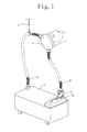
- is a diagram illustrating one configuration of a washing device in accordance with one embodiment of the present invention;
- Fig. 2
- is a diagram illustrating one configuration of the main body of the present invention;
- Fig. 3
- is a sectional view illustrating one configuration of the filter unit of the present invention; and
- Fig. 4
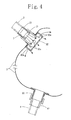
- is a diagram illustrating one configuration of the washing cap of the present invention.
- The main body 1 of the washing device for washing a portion of a user's head according to the present invention is shown in
Fig. 1 . A cleaning liquid is sent out from the main body 1 via adischarge pipe 2. Thedischarge pipe 2 is connected to awashing cap 3. Thewashing cap 3 is attached to a portion of a user's body like a hat, wherein said user is usually a human. The person whose head is to be washed sits on a chair with the devise, and the seat backrest reclines backward to position the user in an approximately upward facing state. The cleaning liquid is discharged from thedischarge pipe 2 into thewashing cap 3 so as to wash the portion of the user's head covered by thewashing cap 3. The cleaning liquid passes from thewashing cap 3 through arecovery pipe 4 and is recovered by afilter unit 5. Hair and dirt such as dandruff are removed by thefilter unit 5 and are recovered by acartridge tank 6. Since thedischarge pipe 2 is suspended in a suitable position by a suspending tool S, when the cleaning liquid is circulated, thedischarge pipe 2 and thewashing cap 3 do not slump downward due to weight of the cleaning liquid. - As shown in
Fig. 2 , thevalve opening mechanism 61 which opens a valve within thecartridge tank 6, saidcartridge tank 6 being set to the main body 1, is provided below thecartridge tank 6. When thecartridge tank 6 is set to the main body 1, as shown inFig. 2 , the inside of thecartridge tank 6 is connected to ascrew pump 12 via acheck valve 11. Aninduction portion 12a of thescrew pump 12 is connected to anair filter 14 via acheck valve 13. Therefore, when thescrew pump 12 is operated, a suitable amount of air as well as the cleaning liquid in thecartridge tank 6 is sucked in by thescrew pump 12 via theair filter 14. Air bubbles are sheared and refined by an impeller which rotates in thescrew pump 12 so that air is dissolved into the cleaning liquid. - The cleaning liquid in which air is dissolved into is discharged together with undissolved air bubbles from a
discharge portion 12b and is sent to a vapor-liquid separatingtank 15. In the vapor-liquid separatingtank 15, the dissolving of the air in the cleaning liquid is further enhanced, and any undissolved air is ejected from arelief valve 15a into the air. - The cleaning liquid in which a lot of air has been dissolved in passes through both the vapor-liquid separating
tank 15 and aheater unit 16 and is discharged from thedischarge pipe 2 into the washing cap 3 (as shown inFig. 1 ). Theheater unit 16 checks the temperature of the cleaning liquid either continuously or periodically, and heats the cleaning liquid so that the cleaning liquid has a pre-set suitable temperature of, for example, approximately 40° Celsius. - With reference to
Fig. 3 , thefilter unit 5 has a cylindrical transparent casemain body 51, and anupper cover 52 and alower cover 53 are screwed into the upper and lower portions of the case main body. Afilter material 54 is attached to approximately half of the casemain body 51. When theupper cover 52 and thelower cover 53 are removed from the casemain body 51, thefilter material 54 can be easily pulled out of the casemain body 51. Therefore, after thefilter unit 5 has been used, theupper cover 52 and thelower cover 53 may be removed from the casemain body 51 and the various respective parts of such washed. Anew filter material 54 may then be attached so that thefilter unit 5 can be reassembled as new. - A
check member 55 is used for checking the color of the recovered cleaning liquid for any unwanted material, and is made of white opaque resin. When thecheck member 55 is inserted into the casemain body 51, aspace 56 is formed over its entire periphery. Since a semicircular canopy top 55a is provided over the upper end of thecheck member 55, the cleaning liquid which passes through therecovery pipe 4 to be recovered collides against thecanopy top 55a and is allowed into thespace 56. The cleaning liquid which overflows from thespace 56 is filtered by thefilter material 54 and is recovered into thecartridge tank 6. - With reference to
Fig. 4 , afemale joining section 31 is attached to a position on thewashing cap 3 corresponding to a portion of a user's forehead at the time of attaching thecap 3 to the user's head. When amale joining section 21 provided at the front end of the dischargedpipe 2 is inserted into thefemale joining section 31, thedischarge pipe 2 is connected to thewashing cap 3. Anozzle unit 7 which generates microbubbles is mounted into thefemale joining section 21. - The
nozzle unit 7 contains a plurality of orifice plates arranged in series. Every time the cleaning liquid passes through each of these orifice plates, the cleaning liquid is compressed and then expanded. The air which is dissolved in the cleaning liquid turns into microbubbles during this process, and as such, microbubbles are generated in the cleaning liquid. - A
flow dividing section 32 is mounted onto the lower-stream side of the female joiningsection 31. A plurality offlow dividing ports 32a is provided to an outer periphery of theflow dividing section 32. The cleaning liquid containing the microbubbles which is discharged from thenozzle unit 7 is dispersed in a plurality of directions by theflow dividing section 32 so as to be discharged into thewashing cap 3. - Further to this, a
male joining section 33 for drainage is mounted onto a position of thewashing cap 3 corresponding to the back of the user's head at the time of attaching thewashing cap 3 to such. A female joiningsection 42 formed on one end of thedischarge pipe 4 is mounted onto themale joining section 33. Therefore, the cleaning liquid discharged into thewashing cap 3 passes through themale joining section 33 and flows out into therecovery pipe 4. - The
male joining section 21 and themale joining section 33 have the same diameter. Therefore, themale joining section 21 of thedischarge pipe 2 can be connected directly to thefemale joining section 42 of therecovery pipe 4 without any need for thewashing cap 3. - With the above detailed configuration, when washing is started, the cartridge tank filled with pure cleaning liquid is set into the main body 1. As a result, the cleaning liquid in the
cartridge tank 6 flows out due to its own weight so that the height of the water in the main body 1 remains relatively constant. As a result, thescrew pump 12 is filled with cleaning liquid, and the cleaning liquid serves as priming water. - The
discharge pipe 2 is connected directly to therecovery pipe 4 without the need for thewashing cap 3. In this state, operation of thescrew pump 12 is then initiated. The cleaning liquid passes from thedischarge pipe 2 through therecovery pipe 4 and into thefilter unit 5 and is recovered into thecartridge tank 6. The cleaning liquid is therefore circulated in this manner. The cleaning liquid is heated by theheater unit 16 during the circulation. When the temperature of the cleaning liquid reaches the set temperature, thescrew pump 12 operation is suspended. Thedischarge pipe 2 is then separated from therecovery pipe 4, and both pipes are connected to thewashing cap 3, which is attached to the user's head. - When all connections are completed, the washing of the user's head is then started. When the
screw pump 12 is again operated, the cleaning liquid heated to the suitable temperature is discharged from thedischarge pipe 2 into thewashing cap 3. A lot of microbubbles are mixed with the cleaning liquid to be discharged, and the head portion is washed by these. The cleaning liquid discharged into thewashing cap 3 passes through therecovery pipe 4 and returns to thefilter unit 5 to be filtered and recovered into thewashing tank 6. This circulating cycle continues for approximately 10 minutes so that the user's head is washed. - When the wash is ended, the
discharge pipe 2 and therecovery pipe 4 are removed from thewashing cap 3 and are connected to each other directly. Thescrew pump 12 is then operated for a few minutes. During this operation, any dirt and unwanted material remaining in thedischarge pipe 4 is filtered by thefilter unit 5. The washing cap is removed from the user's head which has now been washed, and the user's head may be rinsed by a shower in another location. - The used
filter unit 5 is then disassembled and washed, and anew filter material 54 is then inserted so that thefilter unit 5 can be reassembled. Thecartridge tank 6 which recovers the used cleaning liquid is removed from the main body 1, and acartridge tank 6 which is filled with clean water is then inserted into the main body. The clean water is circulated so that the circulation path, including the main body 1, is washed. At this time, therecovery pipe 4 is connected directly to thecartridge tank 6 without first going through thefilter unit 5. - When the wash using the clean water is ended, the
cartridge tank 6 is replaced by another cartridge tank filled with new cleaning liquid, and anew filter unit 5 is mounted thereon. As a result, preparations have been made for the next head washing procedure. - In the above detailed embodiment, one
flow dividing section 32 is mounted into thewashing cap 3, but when a plurality of flow dividing sections is mounted, they are connected by a short duct line. A female joiningsection 31 is mounted onto a joining portion of the duct line, and the flow of the cleaning liquid with which a lot of microbubbles are mixed into is divided into a plurality offlow dividing sections 32a so that the cleaning liquid may be dispersed into thewashing cap 3. - It should be appreciated that the present invention is not limited to the above-detailed embodiment, and various modifications may be made by those skilled in the art, and such modifications may fall within the scope of the present invention.
Claims (5)
- A washing device for washing a portion of a user's head comprising:- a discharge section which discharges a cleaning liquid into a washing cap attached to a portion of the user's head;- a recovery section which drains the cleaning liquid in the washing cap so as to recover it,wherein the cleaning liquid recovered by the recovery section is again discharged from the discharge section and is circulated so as to wash the portion of the user's head covered by the washing device, and
fine air bubbles called microbubbles are mixed with the cleaning liquid to be discharged from the discharge section. - The washing device for washing a portion of a user's head according to claim 1, wherein the discharge section includes a discharge pipe which sends the cleaning liquid to the washing cap and which is detachable from the washing cap, and a nozzle mechanism which generates the microbubbles is mounted to a vicinity of a front end of the discharge pipe.
- The washing device for washing a portion of a user's head according to claim 1, further comprising a dispersing unit which disperses the cleaning liquid to be discharged into the washing cap in a plurality of directions inside the washing cap.
- The washing device for washing a portion of a user's head according to claim 1, wherein the recovery section includes a recovery pipe that is detachable from the washing cap, where the discharge pipe can be detachably connected to the recovery pipe directly without any need for the washing cap.
- The head portion washing device according to claim 1, wherein a filter which removes any dirt mixed with the cleaning liquid recovered by the recovery section is housed in a transparent casing so as to constitute a unit, and the filter unit is replaceable.
Priority Applications (2)
| Application Number | Priority Date | Filing Date | Title |
|---|---|---|---|
| EP07405191A EP2011414B1 (en) | 2007-07-04 | 2007-07-04 | A head washing device |
| AT07405191T ATE524089T1 (en) | 2007-07-04 | 2007-07-04 | HEAD WASHING DEVICE |
Applications Claiming Priority (1)
| Application Number | Priority Date | Filing Date | Title |
|---|---|---|---|
| EP07405191A EP2011414B1 (en) | 2007-07-04 | 2007-07-04 | A head washing device |
Publications (2)
| Publication Number | Publication Date |
|---|---|
| EP2011414A1 true EP2011414A1 (en) | 2009-01-07 |
| EP2011414B1 EP2011414B1 (en) | 2011-09-14 |
Family
ID=38777258
Family Applications (1)
| Application Number | Title | Priority Date | Filing Date |
|---|---|---|---|
| EP07405191A Not-in-force EP2011414B1 (en) | 2007-07-04 | 2007-07-04 | A head washing device |
Country Status (2)
| Country | Link |
|---|---|
| EP (1) | EP2011414B1 (en) |
| AT (1) | ATE524089T1 (en) |
Cited By (1)
| Publication number | Priority date | Publication date | Assignee | Title |
|---|---|---|---|---|
| CN111136056A (en) * | 2020-01-22 | 2020-05-12 | 河南职业技术学院 | Automobile parts belt cleaning device |
Citations (4)
| Publication number | Priority date | Publication date | Assignee | Title |
|---|---|---|---|---|
| US4074369A (en) | 1976-07-08 | 1978-02-21 | Harmon Flossie G | Shampooing unit |
| EP0702912A1 (en) * | 1994-09-22 | 1996-03-27 | ORTHOSTETICA S.r.l. | Method for applying active substance to scalp and apparatus for implementing said method |
| US6024100A (en) * | 1997-06-30 | 2000-02-15 | Hochi Hiroshi | Hair restoring method and apparatus for carrying out the same |
| JP2003210240A (en) | 2002-01-22 | 2003-07-29 | Ricoh Elemex Corp | Scalp cleaner and scattering preventing hood for scalp cleaner |
-
2007
- 2007-07-04 EP EP07405191A patent/EP2011414B1/en not_active Not-in-force
- 2007-07-04 AT AT07405191T patent/ATE524089T1/en not_active IP Right Cessation
Patent Citations (4)
| Publication number | Priority date | Publication date | Assignee | Title |
|---|---|---|---|---|
| US4074369A (en) | 1976-07-08 | 1978-02-21 | Harmon Flossie G | Shampooing unit |
| EP0702912A1 (en) * | 1994-09-22 | 1996-03-27 | ORTHOSTETICA S.r.l. | Method for applying active substance to scalp and apparatus for implementing said method |
| US6024100A (en) * | 1997-06-30 | 2000-02-15 | Hochi Hiroshi | Hair restoring method and apparatus for carrying out the same |
| JP2003210240A (en) | 2002-01-22 | 2003-07-29 | Ricoh Elemex Corp | Scalp cleaner and scattering preventing hood for scalp cleaner |
Cited By (2)
| Publication number | Priority date | Publication date | Assignee | Title |
|---|---|---|---|---|
| CN111136056A (en) * | 2020-01-22 | 2020-05-12 | 河南职业技术学院 | Automobile parts belt cleaning device |
| CN111136056B (en) * | 2020-01-22 | 2022-02-08 | 河南职业技术学院 | Automobile parts belt cleaning device |
Also Published As
| Publication number | Publication date |
|---|---|
| EP2011414B1 (en) | 2011-09-14 |
| ATE524089T1 (en) | 2011-09-15 |
Similar Documents
| Publication | Publication Date | Title |
|---|---|---|
| EP3026166A1 (en) | Circulating drainage apparatus and household appliance | |
| CN106013399B (en) | a floor drain | |
| EP2011414B1 (en) | A head washing device | |
| JP6950884B2 (en) | Hydrogen gas shower water system | |
| TW201032750A (en) | Automatic hair washer | |
| CA2599179C (en) | A head washing device | |
| CN108323907A (en) | A kind of washing device for hair | |
| US7823596B2 (en) | Head washing device | |
| JP4869754B2 (en) | Head washing device | |
| KR100847696B1 (en) | Microbubble Generator | |
| JP2023513396A (en) | Apparatus for root canal preparation and simultaneous irrigation and aspiration | |
| JP2771793B2 (en) | Face wash | |
| JP6869650B2 (en) | Cleaning equipment | |
| CN208836785U (en) | A kind of Pet cleaner | |
| CN213345419U (en) | A bathtub with the function of efficiently filtering the bottom debris | |
| CN208942388U (en) | A kind of bracket and a kind of rinse-system supporting sluice gun | |
| CN209268651U (en) | Bird's nest chooses a mao device | |
| JP3008705U (en) | Cleaning device for human body by slurry | |
| JP7035307B2 (en) | Cleaning equipment | |
| CN210218245U (en) | Filter piece, water pump and bathtub | |
| JPH0824305A (en) | Device for washing human body with slurry | |
| CN108925454A (en) | A kind of Pet cleaner | |
| CN211064679U (en) | Szechwan fish culture pond convenient for removing residues | |
| CN108577998A (en) | A kind of tooth-cleaning device | |
| CN210520872U (en) | Washing type face cleaning instrument |
Legal Events
| Date | Code | Title | Description |
|---|---|---|---|
| PUAI | Public reference made under article 153(3) epc to a published international application that has entered the european phase |
Free format text: ORIGINAL CODE: 0009012 |
|
| AK | Designated contracting states |
Kind code of ref document: A1 Designated state(s): AT BE BG CH CY CZ DE DK EE ES FI FR GB GR HU IE IS IT LI LT LU LV MC MT NL PL PT RO SE SI SK TR |
|
| AX | Request for extension of the european patent |
Extension state: AL BA HR MK RS |
|
| 17P | Request for examination filed |
Effective date: 20090506 |
|
| 17Q | First examination report despatched |
Effective date: 20090608 |
|
| AKX | Designation fees paid |
Designated state(s): AT BE BG CH CY CZ DE DK EE ES FI FR GB GR HU IE IS IT LI LT LU LV MC MT NL PL PT RO SE SI SK TR |
|
| GRAP | Despatch of communication of intention to grant a patent |
Free format text: ORIGINAL CODE: EPIDOSNIGR1 |
|
| GRAS | Grant fee paid |
Free format text: ORIGINAL CODE: EPIDOSNIGR3 |
|
| RIN1 | Information on inventor provided before grant (corrected) |
Inventor name: FUJIKAWA, SUSUMU |
|
| GRAA | (expected) grant |
Free format text: ORIGINAL CODE: 0009210 |
|
| AK | Designated contracting states |
Kind code of ref document: B1 Designated state(s): AT BE BG CH CY CZ DE DK EE ES FI FR GB GR HU IE IS IT LI LT LU LV MC MT NL PL PT RO SE SI SK TR |
|
| REG | Reference to a national code |
Ref country code: GB Ref legal event code: FG4D |
|
| REG | Reference to a national code |
Ref country code: CH Ref legal event code: EP |
|
| REG | Reference to a national code |
Ref country code: IE Ref legal event code: FG4D |
|
| REG | Reference to a national code |
Ref country code: DE Ref legal event code: R096 Ref document number: 602007017157 Country of ref document: DE Effective date: 20111110 |
|
| REG | Reference to a national code |
Ref country code: NL Ref legal event code: VDEP Effective date: 20110914 |
|
| PG25 | Lapsed in a contracting state [announced via postgrant information from national office to epo] |
Ref country code: SE Free format text: LAPSE BECAUSE OF FAILURE TO SUBMIT A TRANSLATION OF THE DESCRIPTION OR TO PAY THE FEE WITHIN THE PRESCRIBED TIME-LIMIT Effective date: 20110914 Ref country code: LT Free format text: LAPSE BECAUSE OF FAILURE TO SUBMIT A TRANSLATION OF THE DESCRIPTION OR TO PAY THE FEE WITHIN THE PRESCRIBED TIME-LIMIT Effective date: 20110914 Ref country code: FI Free format text: LAPSE BECAUSE OF FAILURE TO SUBMIT A TRANSLATION OF THE DESCRIPTION OR TO PAY THE FEE WITHIN THE PRESCRIBED TIME-LIMIT Effective date: 20110914 |
|
| LTIE | Lt: invalidation of european patent or patent extension |
Effective date: 20110914 |
|
| PG25 | Lapsed in a contracting state [announced via postgrant information from national office to epo] |
Ref country code: LV Free format text: LAPSE BECAUSE OF FAILURE TO SUBMIT A TRANSLATION OF THE DESCRIPTION OR TO PAY THE FEE WITHIN THE PRESCRIBED TIME-LIMIT Effective date: 20110914 Ref country code: GR Free format text: LAPSE BECAUSE OF FAILURE TO SUBMIT A TRANSLATION OF THE DESCRIPTION OR TO PAY THE FEE WITHIN THE PRESCRIBED TIME-LIMIT Effective date: 20111215 Ref country code: AT Free format text: LAPSE BECAUSE OF FAILURE TO SUBMIT A TRANSLATION OF THE DESCRIPTION OR TO PAY THE FEE WITHIN THE PRESCRIBED TIME-LIMIT Effective date: 20110914 Ref country code: CY Free format text: LAPSE BECAUSE OF FAILURE TO SUBMIT A TRANSLATION OF THE DESCRIPTION OR TO PAY THE FEE WITHIN THE PRESCRIBED TIME-LIMIT Effective date: 20110914 Ref country code: SI Free format text: LAPSE BECAUSE OF FAILURE TO SUBMIT A TRANSLATION OF THE DESCRIPTION OR TO PAY THE FEE WITHIN THE PRESCRIBED TIME-LIMIT Effective date: 20110914 |
|
| REG | Reference to a national code |
Ref country code: AT Ref legal event code: MK05 Ref document number: 524089 Country of ref document: AT Kind code of ref document: T Effective date: 20110914 |
|
| PG25 | Lapsed in a contracting state [announced via postgrant information from national office to epo] |
Ref country code: BE Free format text: LAPSE BECAUSE OF FAILURE TO SUBMIT A TRANSLATION OF THE DESCRIPTION OR TO PAY THE FEE WITHIN THE PRESCRIBED TIME-LIMIT Effective date: 20110914 |
|
| PG25 | Lapsed in a contracting state [announced via postgrant information from national office to epo] |
Ref country code: IS Free format text: LAPSE BECAUSE OF FAILURE TO SUBMIT A TRANSLATION OF THE DESCRIPTION OR TO PAY THE FEE WITHIN THE PRESCRIBED TIME-LIMIT Effective date: 20120114 Ref country code: SK Free format text: LAPSE BECAUSE OF FAILURE TO SUBMIT A TRANSLATION OF THE DESCRIPTION OR TO PAY THE FEE WITHIN THE PRESCRIBED TIME-LIMIT Effective date: 20110914 Ref country code: CZ Free format text: LAPSE BECAUSE OF FAILURE TO SUBMIT A TRANSLATION OF THE DESCRIPTION OR TO PAY THE FEE WITHIN THE PRESCRIBED TIME-LIMIT Effective date: 20110914 |
|
| PG25 | Lapsed in a contracting state [announced via postgrant information from national office to epo] |
Ref country code: NL Free format text: LAPSE BECAUSE OF FAILURE TO SUBMIT A TRANSLATION OF THE DESCRIPTION OR TO PAY THE FEE WITHIN THE PRESCRIBED TIME-LIMIT Effective date: 20110914 Ref country code: RO Free format text: LAPSE BECAUSE OF FAILURE TO SUBMIT A TRANSLATION OF THE DESCRIPTION OR TO PAY THE FEE WITHIN THE PRESCRIBED TIME-LIMIT Effective date: 20110914 Ref country code: EE Free format text: LAPSE BECAUSE OF FAILURE TO SUBMIT A TRANSLATION OF THE DESCRIPTION OR TO PAY THE FEE WITHIN THE PRESCRIBED TIME-LIMIT Effective date: 20110914 Ref country code: PL Free format text: LAPSE BECAUSE OF FAILURE TO SUBMIT A TRANSLATION OF THE DESCRIPTION OR TO PAY THE FEE WITHIN THE PRESCRIBED TIME-LIMIT Effective date: 20110914 Ref country code: PT Free format text: LAPSE BECAUSE OF FAILURE TO SUBMIT A TRANSLATION OF THE DESCRIPTION OR TO PAY THE FEE WITHIN THE PRESCRIBED TIME-LIMIT Effective date: 20120116 Ref country code: IT Free format text: LAPSE BECAUSE OF FAILURE TO SUBMIT A TRANSLATION OF THE DESCRIPTION OR TO PAY THE FEE WITHIN THE PRESCRIBED TIME-LIMIT Effective date: 20110914 |
|
| PLBE | No opposition filed within time limit |
Free format text: ORIGINAL CODE: 0009261 |
|
| STAA | Information on the status of an ep patent application or granted ep patent |
Free format text: STATUS: NO OPPOSITION FILED WITHIN TIME LIMIT |
|
| PG25 | Lapsed in a contracting state [announced via postgrant information from national office to epo] |
Ref country code: DK Free format text: LAPSE BECAUSE OF FAILURE TO SUBMIT A TRANSLATION OF THE DESCRIPTION OR TO PAY THE FEE WITHIN THE PRESCRIBED TIME-LIMIT Effective date: 20110914 |
|
| 26N | No opposition filed |
Effective date: 20120615 |
|
| REG | Reference to a national code |
Ref country code: DE Ref legal event code: R097 Ref document number: 602007017157 Country of ref document: DE Effective date: 20120615 |
|
| PG25 | Lapsed in a contracting state [announced via postgrant information from national office to epo] |
Ref country code: MC Free format text: LAPSE BECAUSE OF NON-PAYMENT OF DUE FEES Effective date: 20120731 |
|
| REG | Reference to a national code |
Ref country code: CH Ref legal event code: PL |
|
| GBPC | Gb: european patent ceased through non-payment of renewal fee |
Effective date: 20120704 |
|
| PG25 | Lapsed in a contracting state [announced via postgrant information from national office to epo] |
Ref country code: GB Free format text: LAPSE BECAUSE OF NON-PAYMENT OF DUE FEES Effective date: 20120704 Ref country code: LI Free format text: LAPSE BECAUSE OF NON-PAYMENT OF DUE FEES Effective date: 20120731 Ref country code: CH Free format text: LAPSE BECAUSE OF NON-PAYMENT OF DUE FEES Effective date: 20120731 |
|
| REG | Reference to a national code |
Ref country code: IE Ref legal event code: MM4A |
|
| PG25 | Lapsed in a contracting state [announced via postgrant information from national office to epo] |
Ref country code: BG Free format text: LAPSE BECAUSE OF FAILURE TO SUBMIT A TRANSLATION OF THE DESCRIPTION OR TO PAY THE FEE WITHIN THE PRESCRIBED TIME-LIMIT Effective date: 20111214 |
|
| PG25 | Lapsed in a contracting state [announced via postgrant information from national office to epo] |
Ref country code: MT Free format text: LAPSE BECAUSE OF FAILURE TO SUBMIT A TRANSLATION OF THE DESCRIPTION OR TO PAY THE FEE WITHIN THE PRESCRIBED TIME-LIMIT Effective date: 20110914 Ref country code: IE Free format text: LAPSE BECAUSE OF NON-PAYMENT OF DUE FEES Effective date: 20120704 |
|
| PG25 | Lapsed in a contracting state [announced via postgrant information from national office to epo] |
Ref country code: ES Free format text: LAPSE BECAUSE OF FAILURE TO SUBMIT A TRANSLATION OF THE DESCRIPTION OR TO PAY THE FEE WITHIN THE PRESCRIBED TIME-LIMIT Effective date: 20111225 |
|
| PG25 | Lapsed in a contracting state [announced via postgrant information from national office to epo] |
Ref country code: TR Free format text: LAPSE BECAUSE OF FAILURE TO SUBMIT A TRANSLATION OF THE DESCRIPTION OR TO PAY THE FEE WITHIN THE PRESCRIBED TIME-LIMIT Effective date: 20110914 |
|
| PG25 | Lapsed in a contracting state [announced via postgrant information from national office to epo] |
Ref country code: LU Free format text: LAPSE BECAUSE OF NON-PAYMENT OF DUE FEES Effective date: 20120704 |
|
| PG25 | Lapsed in a contracting state [announced via postgrant information from national office to epo] |
Ref country code: HU Free format text: LAPSE BECAUSE OF FAILURE TO SUBMIT A TRANSLATION OF THE DESCRIPTION OR TO PAY THE FEE WITHIN THE PRESCRIBED TIME-LIMIT Effective date: 20070704 |
|
| REG | Reference to a national code |
Ref country code: FR Ref legal event code: PLFP Year of fee payment: 10 |
|
| REG | Reference to a national code |
Ref country code: FR Ref legal event code: PLFP Year of fee payment: 11 |
|
| REG | Reference to a national code |
Ref country code: FR Ref legal event code: PLFP Year of fee payment: 12 |
|
| PGFP | Annual fee paid to national office [announced via postgrant information from national office to epo] |
Ref country code: FR Payment date: 20210728 Year of fee payment: 15 |
|
| PGFP | Annual fee paid to national office [announced via postgrant information from national office to epo] |
Ref country code: DE Payment date: 20210721 Year of fee payment: 15 |
|
| REG | Reference to a national code |
Ref country code: DE Ref legal event code: R119 Ref document number: 602007017157 Country of ref document: DE |
|
| PG25 | Lapsed in a contracting state [announced via postgrant information from national office to epo] |
Ref country code: FR Free format text: LAPSE BECAUSE OF NON-PAYMENT OF DUE FEES Effective date: 20220731 |
|
| PG25 | Lapsed in a contracting state [announced via postgrant information from national office to epo] |
Ref country code: DE Free format text: LAPSE BECAUSE OF NON-PAYMENT OF DUE FEES Effective date: 20230201 |