EP2011088B1 - Contour triangulation system and method - Google Patents
Contour triangulation system and method Download PDFInfo
- Publication number
- EP2011088B1 EP2011088B1 EP07755173.7A EP07755173A EP2011088B1 EP 2011088 B1 EP2011088 B1 EP 2011088B1 EP 07755173 A EP07755173 A EP 07755173A EP 2011088 B1 EP2011088 B1 EP 2011088B1
- Authority
- EP
- European Patent Office
- Prior art keywords
- point
- surface shape
- contour
- contour lines
- contour line
- Prior art date
- Legal status (The legal status is an assumption and is not a legal conclusion. Google has not performed a legal analysis and makes no representation as to the accuracy of the status listed.)
- Active
Links
Images






Classifications
-
- G—PHYSICS
- G06—COMPUTING OR CALCULATING; COUNTING
- G06T—IMAGE DATA PROCESSING OR GENERATION, IN GENERAL
- G06T17/00—Three-dimensional [3D] modelling for computer graphics
- G06T17/20—Finite element generation, e.g. wire-frame surface description, tesselation
Definitions
- the invention relates to a system and method for constructing a surface shape from a plurality of contour lines provided on parallel or substantially parallel planes.
- CT Computed Tomography
- MRI Magnetic Resonance Imaging
- PET Positron Emission Tomography
- SPECT Single Photon Emission Computed Tomography
- ultrasound techniques make it possible to obtain cross sections of the human body.
- a suitable approach for constructing a three dimensional surface of the human anatomy is made from the contour lines of human anatomy by the triangulation of a set of contours created from parallel slices corresponding to different levels. It can be briefly described as joining points of neighboring contour lines to generate triangles. The surface is represented by tessellating those contours, in which triangular elements are obtained to delimit a polyhedron approximating the surface of interest.
- the major problem in surface triangulation is the accuracy of the reconstructed surface and the reliability and complexity of the algorithm.
- the generation of the complex surface preferably will be fast and reliable and suitable for real time application.
- Invention according to claim 1 provides a method of reconstructing a surface shape of an object from a plurality of contour lines, comprising:
- the embodiment is directed to reconstructing a complex surface from a set of parallel contour lines obtained from scanning an object, such as a bone of a patient.
- a CT scan of a patient's anatomy such as the patient's knee
- the embodiment reconstructs a 3D surface of the patient's knee, such as the outer surface of the femur and tibia bone.
- the format of the CT scan file can be obtained in any particular format that is readable by a general purpose computer, such as an Image Guidance System (IGS) format that is converted from a Digital Imaging and Communications in Medicine (DICOM) format, whereby such formats are well known to those skilled in the art.
- IGS Image Guidance System
- DICOM Digital Imaging and Communications in Medicine
- the computer may be any known computing system but is preferably a programmable, processor-based system.
- the computer may include a microprocessor, a hard drive, random access memory (RAM), read only memory (ROM), input/output (I/O) circuitry, and any other well-known computer component.
- the computer is preferably adapted for use with various types of storage devices (persistent and removable), such as, for example, a portable drive, magnetic storage (e.g., a floppy disk), solid state storage (e.g., a flash memory card), optical storage (e.g., a compact disc or CD), and/or network/Internet storage.
- the computer may comprise one or more computers, including, for example, a personal computer (e.g., an IBM-PC compatible computer) or a workstation (e.g., a SUN or Silicon Graphics workstation) operating under a Windows, UNLX, Linux, or other suitable operating system and preferably includes a graphical user interface (GUI).
- a personal computer e.g., an IBM-PC compatible computer
- a workstation e.g., a SUN or Silicon Graphics workstation
- Windows, UNLX, Linux, or other suitable operating system preferably includes a graphical user interface (GUI).
- GUI graphical user interface
- a surface construction of the raw data is made by way of the embodiment, which may be embodied in program code executable by the computer.
- a set of parallel slices (which can be in any orientation, transverse, sagittal, coronal, or oblique), also referred to herein as contour lines, are selected to encompass the entire femur or tibia bone.
- the number of slices can be determined by a trade-off of the work load of femur and tibia segmentation and the resolution of the reconstructed 3D surface.
- a manual segmentation is performed to separate the femur and tibia bone from the rest of the image.
- Any of a number of segmentation schemes can be employed to produce a set of contours in parallel planes, with one contour per plane.
- “Live Wire” segmentation (edge measurement scheme) or “Snakes” segmentation (minimization scheme) may be performed, whereby these segmentation schemes are well known to those skilled in the art.
- the output obtained from scanning an object is a series of parallel images, whereby these images are input to a contouring process (any of ones known to those skilled in the art, such as the ones described above) that produces the contour lines.
- Each contour is represented by a set of contour points.
- the 3D coordinates (x, y, z) of each contour point are saved as the input to a triangulation processing unit.
- these contour points are ordered in the counter-clockwise (CCW) direction.
- CW clockwise
- the triangulation processing unit can be embodied as program code executable by a computer.
- Contour lines can be concave in some areas, flat in other areas, and convex in yet other areas of a segmented scanned image, whereby each contour line is closed (e.g., the first point connects with the second point, the second point connects with the third point, ..., and the last point connects with the first point on the same contour line) and non-intersecting with other contour lines.
- a 'shortest distance' triangulation approach is provided by way of the triangulation processing unit of the computer, which generates a triangle strip between pairs of adjacent parallel contours.
- the 'shortest distance' triangulation approach according to the embodiment is explained in detail hereinbelow.
- a triangulation starts from point Pi on contour1 and point Qj on contour2.
- a next triangulation will pick up either Pil or Qjl to generate the triangle patch PiPilQj or PiQjQjl .
- Pil is the point on contour1 that is closest to point Pi in the CCW direction
- point Qjl is the point on contour 2 that is closest to point Qj in the CCW direction, whereby contour1 and contour2 are adjacently positioned contours.
- Vci is the vector from Pi to the centroid of contour 1
- Vcj is the vector from Qj to the centroid of contour2
- Vcil is the vector from Pil to the centroid of contour1
- Vcjl is the vector from Qjl to the centroid of contour2.
- a first step in the shortest distance scheme is the selecting of the initial points. This initial point determination is done according to the following:
- Figures 2 , 3 , 4 and 5 show the detail process of triangulation by shortest distance metric.
- the following is pseudo code that may be used for the above shortest distance triangulation method.
- k num_contour_points ⁇ 1 + num_contour_points ⁇ 2 ;
- point_i start_point1;
- point_j start_point2;
- the shortest distance solution assumes that triangulations generated by shortest distance have the closest approximation to the actual 3D surface. This is true in most cases. Thus, it generates visually a smooth surface that can approximate virtually any complex 3D surface, such as a tibia or femur of a patient's knee.
- Figure 2 shows the selection of initial points Pi and Qj with shortest distance, whereby two candidate distances PiQjl and PilQj are compared on the next step.
- Figure 3 shows the selection of Qjl as the shortest distance, which results in the generation of triangle patch PiQjQjl.
- Figure 4 shows the updating of Q j to a new position, whereby the two candidate distances PiQjl and PilQj are compared on the next step.
- the new position of Q j corresponds to the position of Q jl in the previous step, as shown in Figure 3 . If the candidate distance PiQjl is the shortest of the two distances in the second step, then the triangle patch PiQ j Qjl is generated.
- FIG. 5 shows the final pattern 500 of the generation of triangle patches between all points of contour1 and contour2, in accordance with the shortest distance approach.
- the shortest distance approach is continued for each respective contour, in order to generate a 3D shape that reasonably approximates the true shape of the object that was scanned by a CT scanner, for example.
- a 'closest orientation' triangulation approach is provided by way of the triangulation processing unit of the computer, which generates a triangle strip between pairs of adjacent parallel contours.
- the 'closest orientation' triangulation approach is explained in detail hereinbelow.
- the embodiment provides a surface shape that reasonably approximates the true surface shape of a scanned object.
- the triangulation processing unit of the embodiment can be embodied as program code executable by a computer.
- a first step in the closest orientation scheme is the selecting of the initial points. This initial point determination is done according to the following:
- Figures 6 through 9 show the detail process of triangulation by closest orientation metric.
- Figure 6 shows initial points Pi and Pj selected based on the initial point selection steps, and whereby orientation pairs ( Vci , Vcjl ) and ( Vcj , Vcil ) are compared at the step.
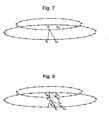
- Figure 7 shows Qjl selected by closet orientation, whereby the vector pair ( Vci , Vcjl ) had the closer orientation (larger value) in this example.
- Triangle patch PiQjQjl is thereby created, as shown in Figure 7.
- Figure 8 shows the updating of Qj to its new position (the position of Qjl in the previous step), whereby the orientation pairs pairs (Vci, Vcjl) and ( Vcj , Vcil ) are compared in this next step.
- Figure 9 shows the final pattern 900 of triangle patches generated from the two contour lines, by using the closest orientation scheme.
- the closest orientation solution generates triangulations that are evenly distributed along the orientation related to the centroid of the contour.
- the closest orientation scheme is sufficient when contours have similar shape and orientation and are mutually centered.
- the embodiment obtains scanned data scanned (e.g., data obtained from a CT scan) from a patient. From that scanned data, a triangulation scheme is performed in order to obtain a surface structure from the scanned data. In the embodiment, the shortest distance scheme is performed first. If the results of that scheme are acceptable, then the process is finished. If the results of that scheme are unacceptable, then the embodiment performs a closest orientation scheme of the same scanned data, and outputs the results as the surface contour data.
- scanned data scanned e.g., data obtained from a CT scan
- a triangulation scheme is performed in order to obtain a surface structure from the scanned data.
- the shortest distance scheme is performed first. If the results of that scheme are acceptable, then the process is finished. If the results of that scheme are unacceptable, then the embodiment performs a closest orientation scheme of the same scanned data, and outputs the results as the surface contour data.
- the closest orientation scheme will generate the correct result in this case.
- the proposed triangulation scheme combines two schemes. First, it generates a triangulation by a shortest distance solution, as explained above. If a wrong result is detected, it switches to the closest orientation solution, and regenerates the triangulations. This will guarantee that the surface is a good approximation to the actual surface and the reconstruction is correct.
- One feature of the embodiment is the determination of when the first triangulation scheme has provided a 'wrong' result. This can be done by checking the respective centroid vectors of the connected points on the two adjacent contours. If the respective centroid vectors point in directions that are at least 90 degrees different from each other, then a wrong result is detected. For example, turning now to Figure 10 , the connected point on the lower contour has a centroid vector that points from the center of the lower contour to the connected point on the lower contour, while the connected point on the upper contour has a centroid vector that points from the center of the upper contour to the connected point on the upper contour, and whereby these two centroid vectors point in 180 degree different directions.
- the first, shortest distance triangulation scheme is stopped, and the second, closest orientation triangulation scheme is then applied to obtain a surface shape from the contour lines.
- the respective centroid vectors are checked, and if they indicate an incorrect result, the embodiment stops the shortest distance scheme, erases the results, and starts the closest orientation scheme.
- the output of the triangulation scheme of the shortest distance approach and the closest orientation approach is a 'set of triangles' list.
- the coordination of three vertices are saved in memory, and are then used for surface rendering, for display on a display (e.g., computer monitor).
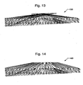
- Figure 13 shows an example of a pattern of triangles 1300 created as a result of using erroneous triangular patches of the shortest distance triangulation scheme. This could have been due to at least one pair of adjacent contour lines having much different sizes from each other, for example.
- Figure 14 shows an example of a pattern of triangles 1400 created as a result of using correct triangular patches of the closest orientation triangulation scheme for the same contours that were used to generate the pattern of triangles 1300 of Figure 13 .
- Figure 15 shows a surface shape 1500 that is generated by an objection model creating unit and displayed based on the triangle patches generated as shown in Figure 14 .
- the generation of a surface shape 1500 from triangle patches and then from stacked triangulated contours is well known in the art, and will not be discussed in this application, for sake of brevity.
- an object model creating unit 255 as shown in Figure 16 is different from conventional object model creating units in that it creates top and bottom portions of the surface shape (or model) by closing top and bottom contours of the stacked triangulated contours by using a respective centroid point as an apex of multiple triangles each formed from adjacent points on the respective top and bottom contours.
- Figure 16 shows one possible system 200 for implementing the embodiment of the invention.
- a scanning unit e.g., a CT scanner
- the scan data is then provided to a computer 205. Note that segmentation of the scan data may be performed by the scanning unit 210 or by the computer 205.
- An assigning unit 220 assigns points to each of the contour lines obtained from the scan data.
- a first triangulation computation unit 230 performs a shortest distance triangulation scheme on the scan data.
- a checking unit 250 checks for errors in the triangles generated by the first triangulation computation unit 230, as explained previously.
- a second triangulation computation unit 240 performs a closest orientation triangulation scheme on the scan data.
- the second triangulation computation unit 240 Based on whether or not the checking unit 250 has determined that an error exists in the triangle patches generated by the first triangulation computation unit 230, the second triangulation computation unit 240 will either do nothing, or will be instructed to perform its closest orientation processing on the scan data.
- the object model creating unit 255 generates a surface shape, or object model, from the triangle patches output by the first triangulation computation unit 230 or the triangle patches output by the second triangulation computation unit 240, in accordance with instructions provided by the checking unit 250.
- the output unit 260 outputs, to a display, the surface shape provided by the object model creating unit 255.
- the structure shown in Figure 16 is for the embodiment.
- embodiment of the present invention provide a contour triangulation apparatus and method in order to obtain a surface structure from scanned image data that includes plural contour lines.
- Other embodiments of the invention will be apparent to those skilled in the art from consideration of the specification and practice of the invention disclosed herein. It is intended that the specification and examples be considered as exemplary only.
Landscapes
- Physics & Mathematics (AREA)
- Engineering & Computer Science (AREA)
- Theoretical Computer Science (AREA)
- Geometry (AREA)
- Software Systems (AREA)
- General Physics & Mathematics (AREA)
- Computer Graphics (AREA)
- Apparatus For Radiation Diagnosis (AREA)
- Image Processing (AREA)
- Image Analysis (AREA)
- Measuring And Recording Apparatus For Diagnosis (AREA)
- Image Generation (AREA)
- Length Measuring Devices By Optical Means (AREA)
Description
- The invention relates to a system and method for constructing a surface shape from a plurality of contour lines provided on parallel or substantially parallel planes.
- In the area of biomedicine, acquiring an accurate three dimensional (3D) surface of the human anatomy (e.g., bones, tumors, tissues) is very helpful in image-guided therapy, such as image-guided surgery, and radiation therapy planning. Computed Tomography (CT), Magnetic Resonance Imaging (MRI), Positron Emission Tomography (PET), Single Photon Emission Computed Tomography (SPECT), and some ultrasound techniques make it possible to obtain cross sections of the human body.
- A suitable approach for constructing a three dimensional surface of the human anatomy is made from the contour lines of human anatomy by the triangulation of a set of contours created from parallel slices corresponding to different levels. It can be briefly described as joining points of neighboring contour lines to generate triangles. The surface is represented by tessellating those contours, in which triangular elements are obtained to delimit a polyhedron approximating the surface of interest. The major problem in surface triangulation is the accuracy of the reconstructed surface and the reliability and complexity of the algorithm.
- In view of the foregoing, a need exists for a contour triangulation system and method that can generate any complex surface with very good accuracy. The generation of the complex surface preferably will be fast and reliable and suitable for real time application.
- A single optimised algorithm for processing complex contour arrangements is described in Cook, P.N., Batnitzky, S. "Three-dimensional Reconstruction from Serial Sections for Medical Applications", Proc. 14th Hawaii Int. Conf. on System Sciences 1981, vol. 2, 358-389. Another algorithm is described in Christiansen, H.N., Sederberg, T.W., "Conversion of Complex Contour Line Definitions into Polygonal Element Mosaics", Proc. 5th Annual Ann. Conf. on Computer Graphics and Interactive Techniques, 1978, 187-192. This algorithm has no automated error analysis, but instead guides a user to find the solution.
- Invention according to
claim 1 provides a method of reconstructing a surface shape of an object from a plurality of contour lines, comprising: - obtaining the plurality of contour lines by scanning the object to obtain scan data and segmenting the scan data;
- assigning points to each of the plurality of contour lines obtained from the segmented scan data, wherein each of the contour lines is closed and non-intersecting with respect to others of the contour lines;
- performing a first triangulation scheme with respect to respective points on two adjacently-positioned contour lines, to determine a first surface shape for a portion of the object corresponding to the two adjacently-positioned contour lines;
- checking, but performing a computer analysis of the first surface shape, the first surface shape to determine if the first surface shape is in error;
- if the first surface shape is not in error, outputting the first surface shape for the portion of the object as determined by the first triangulation scheme, as a reconstructed surface shape for the portion of the object; and
- if the first surface shape is in error,
- performing a second triangulation scheme with respect to the respective points on the two adjacently-positioned contour lines, to determine a second surface shape for the portion of the object corresponding to the two adjacently-positioned contour lines; and
- outputting the second surface shape for the portion of the object as determined by the second triangulation scheme, as a reconstructed surface shape for the portion of the object,
- wherein the first triangulation scheme is a shortest distance scheme, and wherein the second triangulation scheme is a closest orientation scheme.
- The accompanying drawings, which are incorporated in and constitute a part of this specification, illustrate embodiments of the invention and together with the description serve to explain principles of the invention.
-
Figure 1 is a perspective view of two contours for which a shortest distance triangulation scheme is performed in accordance with the embodiment of the present invention. -
Figure 2 is a perspective view of two contours for which initial points have been selected and for which two candidate distances are compared, in accordance with the embodiment of the present invention. -
Figure 3 is a perspective view of two contours for which a first triangle patch has been generated, in accordance with the embodiment of the present invention. -
Figure 4 is a perspective view of two contours for which a next iteration in the triangle patch generation scheme is started, in accordance with the embodiment of the present invention. -
Figure 5 is a perspective view of two contours for which a plurality of triangle patches have been generated, in accordance with the embodiment of the present invention. -
Figure 6 is a perspective view of two contours for which a closest orientation triangulation scheme is performed in accordance with the embodiment of the present invention. -
Figure 7 is a perspective view of two contours for which initial points have been selected and for which two candidate closest orientation vector values are compared, in accordance with the embodiment of the present invention. -
Figure 8 is a perspective view of two contours for which a next iteration in the triangle patch generation scheme is started, in accordance with the embodiment of the present invention. -
Figure 9 is a perspective view of two contours for which a plurality of triangle patches have been generated, in accordance with the embodiment of the present invention. -
Figure 10 is a perspective view of two contours for which an erroneous triangle patch has been generated by using the shortest distance triangulation scheme. -
Figure 11 is a perspective view of two contours for which an upper contour has run out of contour points. -
Figure 12 is a perspective view of two contours for which a plurality of erroneous triangle patches have been generated by using the shortest distance triangulation scheme. -
Figure 13 shows an example of a surface shape created as a result of using erroneous triangular patches of the shortest distance triangulation scheme. -
Figure 14 shows an example of a surface shape created as a result of using correct triangular patches of the closest orientation triangulation scheme for the same contours that were used to generate the surface shape ofFigure 13 . -
Figure 15 shows a surface shape that is generated based on the triangulation patches generated as shown inFigure 14 . -
Figure 16 shows a contour triangulation system in accordance with the embodiment of the invention. - Presently preferred embodiments of the invention are illustrated in the drawings. Although this specification refers primarily to obtaining a surface image of a bone, it should be understood that the subject matter described herein is applicable to other parts of the body, such as, for example, organs, intestines or muscles.
- The embodiment is directed to reconstructing a complex surface from a set of parallel contour lines obtained from scanning an object, such as a bone of a patient. By way of example and not by way of limitation, a CT scan of a patient's anatomy, such as the patient's knee, is made, in a raw data obtaining step, with the scanned data stored in a CT scan file. From that CT scan, the embodiment reconstructs a 3D surface of the patient's knee, such as the outer surface of the femur and tibia bone. The format of the CT scan file can be obtained in any particular format that is readable by a general purpose computer, such as an Image Guidance System (IGS) format that is converted from a Digital Imaging and Communications in Medicine (DICOM) format, whereby such formats are well known to those skilled in the art.
- The computer may be any known computing system but is preferably a programmable, processor-based system. For example, the computer may include a microprocessor, a hard drive, random access memory (RAM), read only memory (ROM), input/output (I/O) circuitry, and any other well-known computer component. The computer is preferably adapted for use with various types of storage devices (persistent and removable), such as, for example, a portable drive, magnetic storage (e.g., a floppy disk), solid state storage (e.g., a flash memory card), optical storage (e.g., a compact disc or CD), and/or network/Internet storage. The computer may comprise one or more computers, including, for example, a personal computer (e.g., an IBM-PC compatible computer) or a workstation (e.g., a SUN or Silicon Graphics workstation) operating under a Windows, UNLX, Linux, or other suitable operating system and preferably includes a graphical user interface (GUI).
- Once the raw data has been obtained and has been loaded onto the computer, or onto a memory accessible by the computer, a surface construction of the raw data is made by way of the embodiment, which may be embodied in program code executable by the computer. From the CT scan file data, a set of parallel slices (which can be in any orientation, transverse, sagittal, coronal, or oblique), also referred to herein as contour lines, are selected to encompass the entire femur or tibia bone. The number of slices can be determined by a trade-off of the work load of femur and tibia segmentation and the resolution of the reconstructed 3D surface. After the number and the position of slices are set, a manual segmentation is performed to separate the femur and tibia bone from the rest of the image. Any of a number of segmentation schemes can be employed to produce a set of contours in parallel planes, with one contour per plane. For example, "Live Wire" segmentation (edge measurement scheme) or "Snakes" segmentation (minimization scheme) may be performed, whereby these segmentation schemes are well known to those skilled in the art. The output obtained from scanning an object is a series of parallel images, whereby these images are input to a contouring process (any of ones known to those skilled in the art, such as the ones described above) that produces the contour lines. Each contour is represented by a set of contour points. The 3D coordinates (x, y, z) of each contour point are saved as the input to a triangulation processing unit. In the embodiment, these contour points are ordered in the counter-clockwise (CCW) direction. Alternatively, they can be ordered in the clockwise (CW) direction. The triangulation processing unit can be embodied as program code executable by a computer. Contour lines can be concave in some areas, flat in other areas, and convex in yet other areas of a segmented scanned image, whereby each contour line is closed (e.g., the first point connects with the second point, the second point connects with the third point, ..., and the last point connects with the first point on the same contour line) and non-intersecting with other contour lines.
- In the embodiment, a 'shortest distance' triangulation approach is provided by way of the triangulation processing unit of the computer, which generates a triangle strip between pairs of adjacent parallel contours. The 'shortest distance' triangulation approach according to the embodiment is explained in detail hereinbelow.
- Referring now to
Figure 1 , a triangulation starts from point Pi on contour1 and point Qj on contour2. A next triangulation will pick up either Pil or Qjl to generate the triangle patch PiPilQj or PiQjQjl. Pil is the point on contour1 that is closest to point Pi in the CCW direction, and point Qjl is the point oncontour 2 that is closest to point Qj in the CCW direction, whereby contour1 and contour2 are adjacently positioned contours. As shown inFigure 1 , Vci is the vector from Pi to the centroid ofcontour 1; Vcj is the vector from Qj to the centroid of contour2; Vcil is the vector from Pil to the centroid of contour1, and Vcjl is the vector from Qjl to the centroid of contour2. - A first step in the shortest distance scheme is the selecting of the initial points. This initial point determination is done according to the following:
- 1) Set the minimum distance dmin to a large number (e.g., 216 -1 for a computer using 16-bit data words).
- 2) Start from one contour point on contour1, compute the distance to each contour point on contour2, and record the shortest distance as ds.
- 3) If ds is less than dmin, set dmin to the ds. Record the position of contour points on contour1 and contour2, by storing them in a memory accessible by the computer.
- 4) Move to another contour point in contour1, repeat steps 2) and 3).
- 5) Stop when all contour points on contour1 are checked.
- Once the initial points have been determined for all points on the contours, the following shortest distance determination steps are performed.
- 1) Select the two points Pi and Qj with the closest distance on contour1 and contour2, respectively.
- 2) Compare the distance from Pi to Qjl, and the distance from Pil to Qj. If Pi and Qjl has shorter distance, then select Qjl to generate triangle patch PiQjQjl. If Pil and Qj has shorter distance, then select Pil to generate triangle patch PiPilQj. See
Figure 2 , which shows the two possible selections as dashed lines in that figure. - 3) Perform steps 1) and 2) iteratively until all contour points have been selected for triangulation.
- 4) If one contour runs out of contour points, then stay at the end point at that contour and only select the neighboring point on the other contour to generate triangle patches in next iterations.
- 5) Stop when all contour points have been selected for triangulation.
-
Figures 2 ,3 ,4 and5 show the detail process of triangulation by shortest distance metric. The following is pseudo code that may be used for the above shortest distance triangulation method.
point_i = start_point1;
point_j = start_point2;
 do {
   distance 1 = dist(point_i, point_j1);
   distance2 = dist(point_i1, point_j);
   if (distance 1 < distance2) {
     point_j = point_j1;
     generate_triangle(i,j,j1);
   } else {
     point_i = point_i1;
     generate_triangle(i,i1,j);
   }
 } while (k > 0);
- 1) Set the closest orientation Orientmax to 0.
- 2) Start from one contour i point on contour1, compute the orientation of vector Vci to each contour point j on contour2. The orientation is the dot product of vectors Vci and Vcj. Store the closest orientation as Orientclosest.
- 3) If Orientclosest is larger than Orientmax, set Orientmax to the Orientclosest. Store the position of contour points on contour1 and contour2.
- 4) Move to another contour point in contour1, and repeat steps 2) and 3).
- 5) Stop when all contour points on contour1 are checked.
- 1) This scheme starts from two points Pi and Qj with closest orientation related to the centroids of contour1 and contour2, respectively.
- 2) The next step compares the orientation of vector pair (Vci, Vcjl) and (Vcj, Vcil). If (Vci, Vcjl) has closer orientation, the next step will select Qil to generate triangle patch PiQjQjl. If (Vcj, Vcil) has closer orientation, the next step will select Pil to generate triangle patch PiPilQj.
- 3) These steps are run iteratively until all contour points are selected for triangulation.
- 4) If one contour runs out of contour points, the closest orientation scheme stays at the end point on that contour and select the neighboring point on the other contour to generate triangle patches in next iterations.
- 5) The closest orientation determination scheme stops when all contour points have been selected for triangulation.

point_i = start_point1;
point_j = start_point2;
 do {
   orient1 = orientation(vector_ci, vector_cjl);
   orient2 = orientation(vector_cil, vector_cj);
   if (orient1 > orient2) {
     point_j = point_jl;
     generate_triangle(i,j,jl);
   } else {
     point_i = point_il;
     generate_triangle(i,il,j);
   }
 } while (k > 0);
- a) For each point on the first contour line, determine a point on the second contour line that is closest to the point on the first contour line.
- b) Set a first triangle leg as a line that connects the point on the second contour line that is closest to the point on the first contour line.
- c) Compare a first distance from the point on the second contour line to an adjacent point on the first contour line that is adjacent the point on the first contour line, to a second distance from an adjacent point on the second contour line to the point on the first contour line.
- d) Based on the comparing performed in step c), set a second triangle leg as a line that connects the shorter one of the first and second distances, and set a third triangle leg as a line that connects either the point and the adjacent point on the first contour line, or the point and the adjacent point on the second contour line.
- e) Check the orientation of the centroid vector for the point on the first contour line to the centroid vector for the point on the second contour line, if orientation is larger than a predetermined value (e.g., 90 degrees), the surface shape is in error, otherwise the surface shape is correct; wherein the orientation is determined by computing the dot product of the centroid vector of the point on the first contour line with the centroid vector of the point on the second contour line, wherein the negative dot product corresponds to the orientation larger than the predetermined value (e.g., 90 degrees).
- f) Repeat steps a) through e) by moving to a next point in either a clockwise direction or a counterclockwise direction on either the first contour line or the second contour line, until all points on the first and second contour lines have been connected to another point on the other of the first and second contour lines.
Claims (14)
- A method of reconstructing a surface shape (1500) of an object from a plurality of contour lines, comprising:obtaining the plurality of contour lines by scanning the object to obtain scan data and segmenting the scan data;assigning points (Pi, Qj; Pil, Qjl) to each of the plurality of contour lines obtained from the segmented scan data, wherein each of the contour lines is closed and non-intersecting with respect to others of the contour lines;performing a first triangulation scheme with respect to respective points (Pi, Qj; Pil, Qjl) on two adjacently-positioned contour lines, to determine a first surface shape for a portion of the object corresponding to the two adjacently-positioned contour lines;checking, by performing a computer analysis of the first surface shape, the first surface shape to determine if the first surface shape is in error;if the first surface shape is not in error, outputting the first surface shape for the portion of the object as determined by the first triangulation scheme, as a reconstructed surface shape for the portion of the object; andif the first surface shape is in error,performing a second triangulation scheme with respect to the respective points (Pi. Qj; Pil, Qjl) on the two adjacently-positioned contour lines, to determine a second surface shape for the portion of the object corresponding to the two adjacently-positioned contour lines; andoutputting the second surface shape for the portion of the object as determined by the second triangulation scheme, as a reconstructed surface shape for the portion of the object,wherein the first triangulation scheme is a shortest distance scheme, and wherein the second triangulation scheme is a closest orientation scheme.
- The method according to claim 1, wherein the checking step comprises:computing respective centroid vectors (Vci, Vcil; Vcj, Vcjl) of connected points (Pi, Qj; Pil, Qjl) on two adjacent ones of the plurality of contour lines of the first surface shape;determining whether or not the respective centroid vectors (vci, Vcil; Vcj, Vcjl) computed in the computing step point in directions that are at least a predetermined angular amount different from each other; anddetermining that the first surface shape is in error when the respective centroid vectors (Vci, Vcil; Vcj, Vcjl) of the two adjacent ones of the plurality of contour lines point in directions that are at least the predetermined angular amount different from each other.
- The method according to claim 1, wherein the object includes a bone structure of a patient.
- The method according to claim 1, further comprising:creating a model of the object from multiple pairs of triangulated contours, wherein the multiple pairs of triangulated contours are stacked on top of each other.
- The method according to claim 1, wherein the checking step comprises:a) for each point (Pi, Pil) on the first contour line, determining a point (Qj, Qjl) on the second contour line that is closest to the point on the first contour line;b) setting a first triangle leg as a line that connects the point (Qj, Qjl) on the second contour line that is closest to the point (Pi, Pil) on the first contour line;c) comparing a first distance from the point (Qj, Qjl) on the second contour line to an adjacent point on the first contour line that is adjacent the point (Pi, Pil) on the first contour line, to a second distance from an adjacent point (Qj, Qjl) on the second contour line to the point (Pi, Pil) on the first contour line;d) based on the comparing step, setting a second triangle leg as a line that connects the shorter one of the first and second distances, and setting a third triangle leg as a line that connects either the point and the adjacent point on the first contour line, or the point and the adjacent point on the second contour line;e) checking the orientation of the centroid vector (Vci, Vcil) for the point on the first contour line to the centroid vector (Vcil, Vcjl) for the point on the second line, if orientation is larger than 90 degrees, the surface shape is in error, otherwise the surface shape is correct; wherein the orientation is determined by computing dot product of the centroid vector (Vci, Vcj) of the point on the first contour line with the centroid vector (Vcil, Vcjl) of the point on the second contour line, wherein the negative dot product corresponds to the orientation larger than 90 degrees;f) repeating steps a) through e) by moving to a next point in either a clockwise direction or a counterclockwise direction on either the first contour line or the second contour line, until all points on the first and second contour lines have been connected to another point on the other of the first and second contour lines.
- A computer program product executable on a computer and configured to compute a surface shape (1500) of an object, the computer program product, when executed on the computer, performing the steps of:obtaining a plurality of contour lines by scanning the object to obtain scan data and segmenting the scan data;assigning points (Pi, Qj; Pil, Qjl) to each of the plurality of contour lines obtained from the segmented scan data, wherein each of the contour lines is closed and non-intersecting with respect to others of the contour lines;performing a first triangulation scheme with respect to respective points (Pi, Qj; Pil, Qjl) on two adjacently-positioned contour lines, to determine a first surface shape for a portion of the object corresponding to the two adjacently-positioned contour lines;checking, by performing a computer analysis of the first surface shape by way of execution of the computer program product on the computer, the first surface shape to determine if the first surface shape is in error;if the first surface shape is not in error, outputting the first surface shape for the portion of the object as determined by the first triangulation scheme, as a reconstructed surface shape for the portion of the object; andif the first surface shape is in error, performing a second triangulation scheme with respect to the respective points (Pi, Qj; Pil, Qjl) on the two adjacently-positioned contour lines, to determine a second surface shape for the portion of the object corresponding to the two adjacently-positioned contour lines; andoutputting the second surface shape for the portion of the object as determined by the second triangulation scheme, as a reconstructed surface shape for the portion of the object,wherein the first triangulation scheme is a shortest distance scheme, and wherein the second triangulation scheme is a closest orientation scheme.
- The computer program product according to claim 6, further comprising:creating a model of the object from multiple pairs of triangulated contours, wherein the multiple pairs of triangulated contours are stacked on top of each other.
- The computer program product according to claim 6, wherein the checking step comprises:a) for each point (Pi, Pil) on the first contour line, determining a point (Qj, Qjl) on the second contour line that is closest to the point on the first contour line;b) setting a first triangle leg as a line that connects the point on second contour line that is closest to the point on the first contour line:c) comparing a first distance from the point on the second contour line to an adjacent point on the first contour line that is adjacent the point on the first contour line, to a second distance from an adjacent point on the second contour line to the point on the first contour line;d) based on the comparing step, setting a second triangle leg as a line that connects the shorter one of the first and second distances, and setting a third triangle leg as line that connects either the point and the adjacent point on the first contour line, or the point and the adjacent point on the second contour line;e) checking the orientation of the centroid vector (Vci, Vcil) for the point on the first contour line to the centroid vector (Vcj, Vcjl) for the point on the second line, if orientation is larger than 90 degrees, the surface shape is in error, otherwise the surface shape is correct; wherein the orientation is determined by computing dot product of the centroid vector (Vci, Vcil) of the point on the first contour line with the centroid vector (Vcj, Vcjl) of the point on the second contour line, wherein the negative dot product corresponds to the orientation larger than 90 degrees;f) repeating steps a) through e) by moving to a next point (Pi, Qj; Pil, Qjl) in either a clockwise direction or a counterclockwise direction on either the first contour line or the second contour line, until all points (Pi, Qj; Pil, Qjl) on the first and second contour lines have been connected to another point on the other of the first and second contour lines.
- The computer program product according to claim 6, wherein the checking step comprises:computing respective centroid vectors (Vci, Vcil; Vcj, Vcjl) of connected points (Pi, Qj; Pil, Qjl) on two adjacent ones of the plurality of contour lines of the first surface shape;determining whether or not the respective centriod vectors (Vci, Vcil; Vcj, Vcjl) computed in the computing step point in directions that are at least a predetermined angular amount different from each other; anddetermining that the first surface shape is in error when the respective centroid vectors (Vci, Vcil; Vcj, Vcjl) of the two adjacent ones of the plurality of contour lines point in directions that are at least the predetermined angular amount different from each other.
- The computer program product according to claim 6, wherein the object includes a bone structure of a patient.
- An apparatus (200) for reconstructing a surface shape (1500) of an object from a plurality of contour lines, comprising:a scanner unit (210) configured to obtain the plurality of contour lines by scanning the object to obtain scan data and to segment the scan data;an assigning unit (220) configured to assign points to each of the plurality of contour lines obtained from the segmented scan data, wherein each of the contour lines is closed and non-intersecting with respect to others of the contour lines;a first triangulation computation unit (230) configured to perform a first triangulation scheme with respect to respective points on two adjacently-positioned contour lines, to determine a first surface shape for a portion of the object corresponding to the two adjacently-positioned contour lines;a checking unit (250) configured to check the first surface shape to determine if the first surface shape is in error;a second triangulation computation unit (240) configured to perform, when the checking unit determines that the first surface shape is in error, a second triangulation scheme with respect to the respective points on the two adjacently-positioned contour lines, to determine a second surface shape for the portion of the object corresponding to the two adjacently-positioned contour lines; andan output and display unit (260) configured to output and display either the first surface shape as output by the first triangulation computation unit (230) or the second surface shape as output by the second triangulation computation unit (240), as a reconstructed surface shape for the portion of the object,wherein the first triangulation computation unit (230) performs a shortest distance triangulation, and wherein the second triangulation computation unit (240) performs a closest orientation triangulation.
- The apparatus according to claim 11, wherein the checking unit (250) comprises:a computing unit configured to compute respective centroid vectors of connected points on two adjacent ones of the plurality of contour lines of the first surface shape;a first determining unit configured to determine whether or not the respective centroid vectors computed in the computing step point in directions that are at least a predetermined angular amount different from each other; anda second determining unit configured to determine that the first surface shape is in error when the respective centroid vectors of the two adjacent ones of the plurality of contour lines point in directions that are at least the predetermined angular amount different from each other.
- The apparatus according to claim 11, wherein the object includes a bone structure of a patient.
- The apparatus according to claim 11, further comprising:an object model creating unit (255) configured to create a model of the object from multiple pairs of triangulated contours, wherein the multiple pairs of triangulated contours are stacked on top of each other.
Applications Claiming Priority (2)
| Application Number | Priority Date | Filing Date | Title |
|---|---|---|---|
| US11/411,951 US7623702B2 (en) | 2006-04-27 | 2006-04-27 | Contour triangulation system and method |
| PCT/US2007/008810 WO2007127047A2 (en) | 2006-04-27 | 2007-04-11 | Contour triangulation system and method |
Publications (2)
| Publication Number | Publication Date |
|---|---|
| EP2011088A2 EP2011088A2 (en) | 2009-01-07 |
| EP2011088B1 true EP2011088B1 (en) | 2015-09-16 |
Family
ID=38514952
Family Applications (1)
| Application Number | Title | Priority Date | Filing Date |
|---|---|---|---|
| EP07755173.7A Active EP2011088B1 (en) | 2006-04-27 | 2007-04-11 | Contour triangulation system and method |
Country Status (7)
| Country | Link |
|---|---|
| US (1) | US7623702B2 (en) |
| EP (1) | EP2011088B1 (en) |
| JP (1) | JP2009535693A (en) |
| CN (1) | CN101467180A (en) |
| AU (1) | AU2007243613A1 (en) |
| CA (1) | CA2650761C (en) |
| WO (1) | WO2007127047A2 (en) |
Families Citing this family (95)
| Publication number | Priority date | Publication date | Assignee | Title |
|---|---|---|---|---|
| US9289253B2 (en) | 2006-02-27 | 2016-03-22 | Biomet Manufacturing, Llc | Patient-specific shoulder guide |
| US20150335438A1 (en) | 2006-02-27 | 2015-11-26 | Biomet Manufacturing, Llc. | Patient-specific augments |
| US9345548B2 (en) | 2006-02-27 | 2016-05-24 | Biomet Manufacturing, Llc | Patient-specific pre-operative planning |
| US8473305B2 (en) | 2007-04-17 | 2013-06-25 | Biomet Manufacturing Corp. | Method and apparatus for manufacturing an implant |
| US8298237B2 (en) | 2006-06-09 | 2012-10-30 | Biomet Manufacturing Corp. | Patient-specific alignment guide for multiple incisions |
| US8070752B2 (en) | 2006-02-27 | 2011-12-06 | Biomet Manufacturing Corp. | Patient specific alignment guide and inter-operative adjustment |
| US8568487B2 (en) | 2006-02-27 | 2013-10-29 | Biomet Manufacturing, Llc | Patient-specific hip joint devices |
| US8608748B2 (en) | 2006-02-27 | 2013-12-17 | Biomet Manufacturing, Llc | Patient specific guides |
| US9918740B2 (en) | 2006-02-27 | 2018-03-20 | Biomet Manufacturing, Llc | Backup surgical instrument system and method |
| US8282646B2 (en) | 2006-02-27 | 2012-10-09 | Biomet Manufacturing Corp. | Patient specific knee alignment guide and associated method |
| US8092465B2 (en) | 2006-06-09 | 2012-01-10 | Biomet Manufacturing Corp. | Patient specific knee alignment guide and associated method |
| US8377066B2 (en) | 2006-02-27 | 2013-02-19 | Biomet Manufacturing Corp. | Patient-specific elbow guides and associated methods |
| US9173661B2 (en) | 2006-02-27 | 2015-11-03 | Biomet Manufacturing, Llc | Patient specific alignment guide with cutting surface and laser indicator |
| US8241293B2 (en) | 2006-02-27 | 2012-08-14 | Biomet Manufacturing Corp. | Patient specific high tibia osteotomy |
| US7967868B2 (en) | 2007-04-17 | 2011-06-28 | Biomet Manufacturing Corp. | Patient-modified implant and associated method |
| US8603180B2 (en) | 2006-02-27 | 2013-12-10 | Biomet Manufacturing, Llc | Patient-specific acetabular alignment guides |
| US9907659B2 (en) | 2007-04-17 | 2018-03-06 | Biomet Manufacturing, Llc | Method and apparatus for manufacturing an implant |
| US8133234B2 (en) | 2006-02-27 | 2012-03-13 | Biomet Manufacturing Corp. | Patient specific acetabular guide and method |
| US8864769B2 (en) | 2006-02-27 | 2014-10-21 | Biomet Manufacturing, Llc | Alignment guides with patient-specific anchoring elements |
| US8591516B2 (en) | 2006-02-27 | 2013-11-26 | Biomet Manufacturing, Llc | Patient-specific orthopedic instruments |
| US10278711B2 (en) | 2006-02-27 | 2019-05-07 | Biomet Manufacturing, Llc | Patient-specific femoral guide |
| US9113971B2 (en) | 2006-02-27 | 2015-08-25 | Biomet Manufacturing, Llc | Femoral acetabular impingement guide |
| US8407067B2 (en) | 2007-04-17 | 2013-03-26 | Biomet Manufacturing Corp. | Method and apparatus for manufacturing an implant |
| US8858561B2 (en) | 2006-06-09 | 2014-10-14 | Blomet Manufacturing, LLC | Patient-specific alignment guide |
| US8535387B2 (en) | 2006-02-27 | 2013-09-17 | Biomet Manufacturing, Llc | Patient-specific tools and implants |
| US9339278B2 (en) | 2006-02-27 | 2016-05-17 | Biomet Manufacturing, Llc | Patient-specific acetabular guides and associated instruments |
| US8608749B2 (en) | 2006-02-27 | 2013-12-17 | Biomet Manufacturing, Llc | Patient-specific acetabular guides and associated instruments |
| US7623702B2 (en) * | 2006-04-27 | 2009-11-24 | Mako Surgical Corp. | Contour triangulation system and method |
| DE102006022831A1 (en) * | 2006-05-16 | 2007-11-22 | Siemens Ag | Method of controlling a grinding machine and numerically controlled grinding machine |
| US9795399B2 (en) | 2006-06-09 | 2017-10-24 | Biomet Manufacturing, Llc | Patient-specific knee alignment guide and associated method |
| US8265949B2 (en) | 2007-09-27 | 2012-09-11 | Depuy Products, Inc. | Customized patient surgical plan |
| JP4437333B2 (en) * | 2007-09-28 | 2010-03-24 | ジーイー・メディカル・システムズ・グローバル・テクノロジー・カンパニー・エルエルシー | Image processing method, image processing apparatus, and program |
| US8425524B2 (en) | 2007-09-30 | 2013-04-23 | DePuy Synthes Products, LLC | Customized patient-specific multi-cutting blocks |
| US8357111B2 (en) | 2007-09-30 | 2013-01-22 | Depuy Products, Inc. | Method and system for designing patient-specific orthopaedic surgical instruments |
| US8249345B2 (en) * | 2008-06-27 | 2012-08-21 | Mako Surgical Corp. | Automatic image segmentation using contour propagation |
| US8848974B2 (en) * | 2008-09-29 | 2014-09-30 | Restoration Robotics, Inc. | Object-tracking systems and methods |
| US8170641B2 (en) | 2009-02-20 | 2012-05-01 | Biomet Manufacturing Corp. | Method of imaging an extremity of a patient |
| DE102009028503B4 (en) | 2009-08-13 | 2013-11-14 | Biomet Manufacturing Corp. | Resection template for the resection of bones, method for producing such a resection template and operation set for performing knee joint surgery |
| US8632547B2 (en) | 2010-02-26 | 2014-01-21 | Biomet Sports Medicine, Llc | Patient-specific osteotomy devices and methods |
| US9066727B2 (en) | 2010-03-04 | 2015-06-30 | Materialise Nv | Patient-specific computed tomography guides |
| EP2384714A1 (en) | 2010-05-03 | 2011-11-09 | Universitat Politècnica de Catalunya | A method for defining working space limits in robotic surgery |
| FR2963693B1 (en) | 2010-08-04 | 2013-05-03 | Medtech | PROCESS FOR AUTOMATED ACQUISITION AND ASSISTED ANATOMICAL SURFACES |
| US8463021B2 (en) * | 2010-09-16 | 2013-06-11 | Indian Institute Of Technology Kanpur | Four dimensional reconstruction and characterization system |
| US8679125B2 (en) | 2010-09-22 | 2014-03-25 | Biomet Manufacturing, Llc | Robotic guided femoral head reshaping |
| US9271744B2 (en) | 2010-09-29 | 2016-03-01 | Biomet Manufacturing, Llc | Patient-specific guide for partial acetabular socket replacement |
| US9968376B2 (en) | 2010-11-29 | 2018-05-15 | Biomet Manufacturing, Llc | Patient-specific orthopedic instruments |
| US8503753B2 (en) * | 2010-12-02 | 2013-08-06 | Kabushiki Kaisha Toshiba | System and method for triangular interpolation in image reconstruction for PET |
| US8911453B2 (en) | 2010-12-21 | 2014-12-16 | Restoration Robotics, Inc. | Methods and systems for directing movement of a tool in hair transplantation procedures |
| US9498289B2 (en) | 2010-12-21 | 2016-11-22 | Restoration Robotics, Inc. | Methods and systems for directing movement of a tool in hair transplantation procedures |
| US9241745B2 (en) | 2011-03-07 | 2016-01-26 | Biomet Manufacturing, Llc | Patient-specific femoral version guide |
| US8715289B2 (en) | 2011-04-15 | 2014-05-06 | Biomet Manufacturing, Llc | Patient-specific numerically controlled instrument |
| US9675400B2 (en) | 2011-04-19 | 2017-06-13 | Biomet Manufacturing, Llc | Patient-specific fracture fixation instrumentation and method |
| US8956364B2 (en) | 2011-04-29 | 2015-02-17 | Biomet Manufacturing, Llc | Patient-specific partial knee guides and other instruments |
| US8668700B2 (en) | 2011-04-29 | 2014-03-11 | Biomet Manufacturing, Llc | Patient-specific convertible guides |
| US8532807B2 (en) | 2011-06-06 | 2013-09-10 | Biomet Manufacturing, Llc | Pre-operative planning and manufacturing method for orthopedic procedure |
| CN102222336B (en) * | 2011-06-10 | 2013-04-10 | 复旦大学 | Three-dimensional reconstruction technology-based diaphragm surface area calculation method and system |
| US9084618B2 (en) | 2011-06-13 | 2015-07-21 | Biomet Manufacturing, Llc | Drill guides for confirming alignment of patient-specific alignment guides |
| US20130001121A1 (en) | 2011-07-01 | 2013-01-03 | Biomet Manufacturing Corp. | Backup kit for a patient-specific arthroplasty kit assembly |
| US8764760B2 (en) | 2011-07-01 | 2014-07-01 | Biomet Manufacturing, Llc | Patient-specific bone-cutting guidance instruments and methods |
| US8597365B2 (en) | 2011-08-04 | 2013-12-03 | Biomet Manufacturing, Llc | Patient-specific pelvic implants for acetabular reconstruction |
| US9066734B2 (en) | 2011-08-31 | 2015-06-30 | Biomet Manufacturing, Llc | Patient-specific sacroiliac guides and associated methods |
| US9295497B2 (en) | 2011-08-31 | 2016-03-29 | Biomet Manufacturing, Llc | Patient-specific sacroiliac and pedicle guides |
| US9386993B2 (en) | 2011-09-29 | 2016-07-12 | Biomet Manufacturing, Llc | Patient-specific femoroacetabular impingement instruments and methods |
| WO2013062848A1 (en) | 2011-10-27 | 2013-05-02 | Biomet Manufacturing Corporation | Patient-specific glenoid guides |
| US9301812B2 (en) | 2011-10-27 | 2016-04-05 | Biomet Manufacturing, Llc | Methods for patient-specific shoulder arthroplasty |
| KR20130046336A (en) | 2011-10-27 | 2013-05-07 | 삼성전자주식회사 | Multi-view device of display apparatus and contol method thereof, and display system |
| US9451973B2 (en) | 2011-10-27 | 2016-09-27 | Biomet Manufacturing, Llc | Patient specific glenoid guide |
| US9554910B2 (en) | 2011-10-27 | 2017-01-31 | Biomet Manufacturing, Llc | Patient-specific glenoid guide and implants |
| FR2983059B1 (en) | 2011-11-30 | 2014-11-28 | Medtech | ROBOTIC-ASSISTED METHOD OF POSITIONING A SURGICAL INSTRUMENT IN RELATION TO THE BODY OF A PATIENT AND DEVICE FOR CARRYING OUT SAID METHOD |
| US9237950B2 (en) | 2012-02-02 | 2016-01-19 | Biomet Manufacturing, Llc | Implant with patient-specific porous structure |
| CN102855658B (en) * | 2012-07-17 | 2015-02-18 | 天津大学 | Three-dimensional reconstruction method based on meteorological radar base data |
| US9060788B2 (en) | 2012-12-11 | 2015-06-23 | Biomet Manufacturing, Llc | Patient-specific acetabular guide for anterior approach |
| US9204977B2 (en) | 2012-12-11 | 2015-12-08 | Biomet Manufacturing, Llc | Patient-specific acetabular guide for anterior approach |
| US9839438B2 (en) | 2013-03-11 | 2017-12-12 | Biomet Manufacturing, Llc | Patient-specific glenoid guide with a reusable guide holder |
| US9579107B2 (en) | 2013-03-12 | 2017-02-28 | Biomet Manufacturing, Llc | Multi-point fit for patient specific guide |
| US9498233B2 (en) | 2013-03-13 | 2016-11-22 | Biomet Manufacturing, Llc. | Universal acetabular guide and associated hardware |
| US9826981B2 (en) | 2013-03-13 | 2017-11-28 | Biomet Manufacturing, Llc | Tangential fit of patient-specific guides |
| US9517145B2 (en) | 2013-03-15 | 2016-12-13 | Biomet Manufacturing, Llc | Guide alignment system and method |
| US20150112349A1 (en) | 2013-10-21 | 2015-04-23 | Biomet Manufacturing, Llc | Ligament Guide Registration |
| CN106062511B (en) * | 2013-12-05 | 2018-12-04 | 特林布尔有限公司 | Geodetic instrument and method of operating a geodetic instrument |
| RU2014111793A (en) * | 2014-03-27 | 2015-10-10 | ЭлЭсАй Корпорейшн | PROCESSOR OF PROCESSING IMAGES WITH RECOGNITION OF STATIC POSES OF HAND USING TRIANGULATION AND SMOOTHING OF CIRCUITS |
| US10282488B2 (en) | 2014-04-25 | 2019-05-07 | Biomet Manufacturing, Llc | HTO guide with optional guided ACL/PCL tunnels |
| US9408616B2 (en) | 2014-05-12 | 2016-08-09 | Biomet Manufacturing, Llc | Humeral cut guide |
| US9561040B2 (en) | 2014-06-03 | 2017-02-07 | Biomet Manufacturing, Llc | Patient-specific glenoid depth control |
| US9839436B2 (en) | 2014-06-03 | 2017-12-12 | Biomet Manufacturing, Llc | Patient-specific glenoid depth control |
| US9833245B2 (en) | 2014-09-29 | 2017-12-05 | Biomet Sports Medicine, Llc | Tibial tubercule osteotomy |
| US9826994B2 (en) | 2014-09-29 | 2017-11-28 | Biomet Manufacturing, Llc | Adjustable glenoid pin insertion guide |
| US9820868B2 (en) | 2015-03-30 | 2017-11-21 | Biomet Manufacturing, Llc | Method and apparatus for a pin apparatus |
| US10568647B2 (en) | 2015-06-25 | 2020-02-25 | Biomet Manufacturing, Llc | Patient-specific humeral guide designs |
| US10226262B2 (en) | 2015-06-25 | 2019-03-12 | Biomet Manufacturing, Llc | Patient-specific humeral guide designs |
| US10722310B2 (en) | 2017-03-13 | 2020-07-28 | Zimmer Biomet CMF and Thoracic, LLC | Virtual surgery planning system and method |
| US11051829B2 (en) | 2018-06-26 | 2021-07-06 | DePuy Synthes Products, Inc. | Customized patient-specific orthopaedic surgical instrument |
| US11478307B2 (en) | 2018-12-18 | 2022-10-25 | Mako Surgical Corp. | Systems and methods for fiber optic tracking |
| US11893745B2 (en) * | 2020-12-09 | 2024-02-06 | Raytheon Company | System and method for generating and displaying contours |
| CN117078891B (en) * | 2023-10-17 | 2024-01-09 | 西安第六镜网络科技有限公司 | Laser contour mesh reconstruction method and device, electronic equipment and storage medium |
Family Cites Families (10)
| Publication number | Priority date | Publication date | Assignee | Title |
|---|---|---|---|---|
| US6044170A (en) * | 1996-03-21 | 2000-03-28 | Real-Time Geometry Corporation | System and method for rapid shape digitizing and adaptive mesh generation |
| US6858826B2 (en) * | 1996-10-25 | 2005-02-22 | Waveworx Inc. | Method and apparatus for scanning three-dimensional objects |
| US6415171B1 (en) * | 1999-07-16 | 2002-07-02 | International Business Machines Corporation | System and method for fusing three-dimensional shape data on distorted images without correcting for distortion |
| US7084868B2 (en) * | 2000-04-26 | 2006-08-01 | University Of Louisville Research Foundation, Inc. | System and method for 3-D digital reconstruction of an oral cavity from a sequence of 2-D images |
| US20040017369A1 (en) * | 2002-01-22 | 2004-01-29 | Hultgren Bruce Willard | Method and apparatus for computer generation of electronic model images |
| US7324132B2 (en) * | 2003-05-06 | 2008-01-29 | Hewlett-Packard Development Company, L.P. | Imaging three-dimensional objects |
| US20060017720A1 (en) * | 2004-07-15 | 2006-01-26 | Li You F | System and method for 3D measurement and surface reconstruction |
| JP4480083B2 (en) * | 2005-02-23 | 2010-06-16 | アイシン精機株式会社 | Object recognition device |
| US7545979B2 (en) * | 2005-04-12 | 2009-06-09 | General Electric Company | Method and system for automatically segmenting organs from three dimensional computed tomography images |
| US7623702B2 (en) * | 2006-04-27 | 2009-11-24 | Mako Surgical Corp. | Contour triangulation system and method |
-
2006
- 2006-04-27 US US11/411,951 patent/US7623702B2/en active Active
-
2007
- 2007-04-11 AU AU2007243613A patent/AU2007243613A1/en not_active Abandoned
- 2007-04-11 CN CNA2007800213063A patent/CN101467180A/en active Pending
- 2007-04-11 EP EP07755173.7A patent/EP2011088B1/en active Active
- 2007-04-11 JP JP2009507706A patent/JP2009535693A/en not_active Withdrawn
- 2007-04-11 WO PCT/US2007/008810 patent/WO2007127047A2/en not_active Ceased
- 2007-04-11 CA CA2650761A patent/CA2650761C/en active Active
Also Published As
| Publication number | Publication date |
|---|---|
| WO2007127047A3 (en) | 2007-12-27 |
| JP2009535693A (en) | 2009-10-01 |
| AU2007243613A1 (en) | 2007-11-08 |
| EP2011088A2 (en) | 2009-01-07 |
| US7623702B2 (en) | 2009-11-24 |
| CA2650761A1 (en) | 2007-11-08 |
| CN101467180A (en) | 2009-06-24 |
| US20070253617A1 (en) | 2007-11-01 |
| CA2650761C (en) | 2015-06-09 |
| WO2007127047A2 (en) | 2007-11-08 |
Similar Documents
| Publication | Publication Date | Title |
|---|---|---|
| US7623702B2 (en) | Contour triangulation system and method | |
| US6362821B1 (en) | Surface model generation for visualizing three-dimensional objects using multiple elastic surface nets | |
| Kyung et al. | Perspective projection-based 3d ct reconstruction from biplanar x-rays | |
| EP2646979B1 (en) | Image registration apparatus | |
| US8543338B2 (en) | System and method for performing computerized simulations for image-guided procedures using a patient specific model | |
| JP4575157B2 (en) | Simultaneous segmentation of multiple objects or multiple objects with mesh adaptation | |
| WO2008016544A2 (en) | Region delineation, image registration and image fusion for radiation therapy | |
| JP6285434B2 (en) | Dose deformation error calculation method and system | |
| CN116524118B (en) | Multimodal rendering method based on 3D dental CBCT data and oral scan model | |
| EP4249049B1 (en) | Method and system for robust radiotherapy treatment planning for dose mapping uncertainties | |
| Balestra et al. | Articulated statistical shape model-based 2D-3D reconstruction of a hip joint | |
| CN111445479A (en) | Method and device for segmentation of regions of interest in medical images | |
| Posiewnik et al. | Utility of deformable image registration for adaptive prostate cancer treatment. Analysis and comparison of two commercially available algorithms | |
| Prümmer et al. | 2d-3d non-rigid registration using iterative reconstruction | |
| Kim et al. | Dense femur reconstruction from two x-ray images using generic 3D model with twist correction | |
| CN117338318A (en) | Three-dimensional shape data generation method, information processing device and recording medium | |
| Antila et al. | Automatic extraction of mandibular bone geometry for anatomy-based synthetization of radiographs | |
| Guéziec | Extracting surface models of the anatomy from medical images |
Legal Events
| Date | Code | Title | Description |
|---|---|---|---|
| PUAI | Public reference made under article 153(3) epc to a published international application that has entered the european phase |
Free format text: ORIGINAL CODE: 0009012 |
|
| 17P | Request for examination filed |
Effective date: 20081024 |
|
| AK | Designated contracting states |
Kind code of ref document: A2 Designated state(s): AT BE BG CH CY CZ DE DK EE ES FI FR GB GR HU IE IS IT LI LT LU LV MC MT NL PL PT RO SE SI SK TR |
|
| AX | Request for extension of the european patent |
Extension state: AL BA HR MK RS |
|
| DAX | Request for extension of the european patent (deleted) | ||
| 17Q | First examination report despatched |
Effective date: 20100205 |
|
| GRAP | Despatch of communication of intention to grant a patent |
Free format text: ORIGINAL CODE: EPIDOSNIGR1 |
|
| INTG | Intention to grant announced |
Effective date: 20150416 |
|
| GRAS | Grant fee paid |
Free format text: ORIGINAL CODE: EPIDOSNIGR3 |
|
| GRAA | (expected) grant |
Free format text: ORIGINAL CODE: 0009210 |
|
| AK | Designated contracting states |
Kind code of ref document: B1 Designated state(s): AT BE BG CH CY CZ DE DK EE ES FI FR GB GR HU IE IS IT LI LT LU LV MC MT NL PL PT RO SE SI SK TR |
|
| REG | Reference to a national code |
Ref country code: GB Ref legal event code: FG4D |
|
| REG | Reference to a national code |
Ref country code: CH Ref legal event code: EP |
|
| REG | Reference to a national code |
Ref country code: IE Ref legal event code: FG4D |
|
| REG | Reference to a national code |
Ref country code: AT Ref legal event code: REF Ref document number: 750322 Country of ref document: AT Kind code of ref document: T Effective date: 20151015 |
|
| REG | Reference to a national code |
Ref country code: DE Ref legal event code: R096 Ref document number: 602007043148 Country of ref document: DE |
|
| REG | Reference to a national code |
Ref country code: NL Ref legal event code: MP Effective date: 20150916 |
|
| PG25 | Lapsed in a contracting state [announced via postgrant information from national office to epo] |
Ref country code: GR Free format text: LAPSE BECAUSE OF FAILURE TO SUBMIT A TRANSLATION OF THE DESCRIPTION OR TO PAY THE FEE WITHIN THE PRESCRIBED TIME-LIMIT Effective date: 20151217 Ref country code: LT Free format text: LAPSE BECAUSE OF FAILURE TO SUBMIT A TRANSLATION OF THE DESCRIPTION OR TO PAY THE FEE WITHIN THE PRESCRIBED TIME-LIMIT Effective date: 20150916 Ref country code: FI Free format text: LAPSE BECAUSE OF FAILURE TO SUBMIT A TRANSLATION OF THE DESCRIPTION OR TO PAY THE FEE WITHIN THE PRESCRIBED TIME-LIMIT Effective date: 20150916 Ref country code: LV Free format text: LAPSE BECAUSE OF FAILURE TO SUBMIT A TRANSLATION OF THE DESCRIPTION OR TO PAY THE FEE WITHIN THE PRESCRIBED TIME-LIMIT Effective date: 20150916 |
|
| REG | Reference to a national code |
Ref country code: LT Ref legal event code: MG4D |
|
| REG | Reference to a national code |
Ref country code: AT Ref legal event code: MK05 Ref document number: 750322 Country of ref document: AT Kind code of ref document: T Effective date: 20150916 |
|
| PG25 | Lapsed in a contracting state [announced via postgrant information from national office to epo] |
Ref country code: SE Free format text: LAPSE BECAUSE OF FAILURE TO SUBMIT A TRANSLATION OF THE DESCRIPTION OR TO PAY THE FEE WITHIN THE PRESCRIBED TIME-LIMIT Effective date: 20150916 |
|
| REG | Reference to a national code |
Ref country code: FR Ref legal event code: PLFP Year of fee payment: 10 |
|
| PG25 | Lapsed in a contracting state [announced via postgrant information from national office to epo] |
Ref country code: NL Free format text: LAPSE BECAUSE OF FAILURE TO SUBMIT A TRANSLATION OF THE DESCRIPTION OR TO PAY THE FEE WITHIN THE PRESCRIBED TIME-LIMIT Effective date: 20150916 |
|
| PG25 | Lapsed in a contracting state [announced via postgrant information from national office to epo] |
Ref country code: EE Free format text: LAPSE BECAUSE OF FAILURE TO SUBMIT A TRANSLATION OF THE DESCRIPTION OR TO PAY THE FEE WITHIN THE PRESCRIBED TIME-LIMIT Effective date: 20150916 Ref country code: SK Free format text: LAPSE BECAUSE OF FAILURE TO SUBMIT A TRANSLATION OF THE DESCRIPTION OR TO PAY THE FEE WITHIN THE PRESCRIBED TIME-LIMIT Effective date: 20150916 Ref country code: CZ Free format text: LAPSE BECAUSE OF FAILURE TO SUBMIT A TRANSLATION OF THE DESCRIPTION OR TO PAY THE FEE WITHIN THE PRESCRIBED TIME-LIMIT Effective date: 20150916 Ref country code: IS Free format text: LAPSE BECAUSE OF FAILURE TO SUBMIT A TRANSLATION OF THE DESCRIPTION OR TO PAY THE FEE WITHIN THE PRESCRIBED TIME-LIMIT Effective date: 20160116 Ref country code: ES Free format text: LAPSE BECAUSE OF FAILURE TO SUBMIT A TRANSLATION OF THE DESCRIPTION OR TO PAY THE FEE WITHIN THE PRESCRIBED TIME-LIMIT Effective date: 20150916 |
|
| PG25 | Lapsed in a contracting state [announced via postgrant information from national office to epo] |
Ref country code: PL Free format text: LAPSE BECAUSE OF FAILURE TO SUBMIT A TRANSLATION OF THE DESCRIPTION OR TO PAY THE FEE WITHIN THE PRESCRIBED TIME-LIMIT Effective date: 20150916 Ref country code: RO Free format text: LAPSE BECAUSE OF FAILURE TO SUBMIT A TRANSLATION OF THE DESCRIPTION OR TO PAY THE FEE WITHIN THE PRESCRIBED TIME-LIMIT Effective date: 20150916 Ref country code: PT Free format text: LAPSE BECAUSE OF FAILURE TO SUBMIT A TRANSLATION OF THE DESCRIPTION OR TO PAY THE FEE WITHIN THE PRESCRIBED TIME-LIMIT Effective date: 20160118 Ref country code: AT Free format text: LAPSE BECAUSE OF FAILURE TO SUBMIT A TRANSLATION OF THE DESCRIPTION OR TO PAY THE FEE WITHIN THE PRESCRIBED TIME-LIMIT Effective date: 20150916 |
|
| REG | Reference to a national code |
Ref country code: DE Ref legal event code: R097 Ref document number: 602007043148 Country of ref document: DE |
|
| PLBE | No opposition filed within time limit |
Free format text: ORIGINAL CODE: 0009261 |
|
| STAA | Information on the status of an ep patent application or granted ep patent |
Free format text: STATUS: NO OPPOSITION FILED WITHIN TIME LIMIT |
|
| 26N | No opposition filed |
Effective date: 20160617 |
|
| PG25 | Lapsed in a contracting state [announced via postgrant information from national office to epo] |
Ref country code: BE Free format text: LAPSE BECAUSE OF NON-PAYMENT OF DUE FEES Effective date: 20160430 Ref country code: DK Free format text: LAPSE BECAUSE OF FAILURE TO SUBMIT A TRANSLATION OF THE DESCRIPTION OR TO PAY THE FEE WITHIN THE PRESCRIBED TIME-LIMIT Effective date: 20150916 |
|
| PG25 | Lapsed in a contracting state [announced via postgrant information from national office to epo] |
Ref country code: SI Free format text: LAPSE BECAUSE OF FAILURE TO SUBMIT A TRANSLATION OF THE DESCRIPTION OR TO PAY THE FEE WITHIN THE PRESCRIBED TIME-LIMIT Effective date: 20150916 |
|
| REG | Reference to a national code |
Ref country code: CH Ref legal event code: PL |
|
| PG25 | Lapsed in a contracting state [announced via postgrant information from national office to epo] |
Ref country code: LU Free format text: LAPSE BECAUSE OF FAILURE TO SUBMIT A TRANSLATION OF THE DESCRIPTION OR TO PAY THE FEE WITHIN THE PRESCRIBED TIME-LIMIT Effective date: 20160411 Ref country code: BE Free format text: LAPSE BECAUSE OF FAILURE TO SUBMIT A TRANSLATION OF THE DESCRIPTION OR TO PAY THE FEE WITHIN THE PRESCRIBED TIME-LIMIT Effective date: 20150916 |
|
| REG | Reference to a national code |
Ref country code: IE Ref legal event code: MM4A |
|
| PG25 | Lapsed in a contracting state [announced via postgrant information from national office to epo] |
Ref country code: CH Free format text: LAPSE BECAUSE OF NON-PAYMENT OF DUE FEES Effective date: 20160430 Ref country code: LI Free format text: LAPSE BECAUSE OF NON-PAYMENT OF DUE FEES Effective date: 20160430 |
|
| REG | Reference to a national code |
Ref country code: FR Ref legal event code: PLFP Year of fee payment: 11 |
|
| PG25 | Lapsed in a contracting state [announced via postgrant information from national office to epo] |
Ref country code: IE Free format text: LAPSE BECAUSE OF NON-PAYMENT OF DUE FEES Effective date: 20160411 |
|
| REG | Reference to a national code |
Ref country code: FR Ref legal event code: PLFP Year of fee payment: 12 |
|
| PG25 | Lapsed in a contracting state [announced via postgrant information from national office to epo] |
Ref country code: CY Free format text: LAPSE BECAUSE OF FAILURE TO SUBMIT A TRANSLATION OF THE DESCRIPTION OR TO PAY THE FEE WITHIN THE PRESCRIBED TIME-LIMIT Effective date: 20150916 Ref country code: HU Free format text: LAPSE BECAUSE OF FAILURE TO SUBMIT A TRANSLATION OF THE DESCRIPTION OR TO PAY THE FEE WITHIN THE PRESCRIBED TIME-LIMIT; INVALID AB INITIO Effective date: 20070411 |
|
| PG25 | Lapsed in a contracting state [announced via postgrant information from national office to epo] |
Ref country code: TR Free format text: LAPSE BECAUSE OF FAILURE TO SUBMIT A TRANSLATION OF THE DESCRIPTION OR TO PAY THE FEE WITHIN THE PRESCRIBED TIME-LIMIT Effective date: 20150916 Ref country code: MC Free format text: LAPSE BECAUSE OF FAILURE TO SUBMIT A TRANSLATION OF THE DESCRIPTION OR TO PAY THE FEE WITHIN THE PRESCRIBED TIME-LIMIT Effective date: 20150916 Ref country code: MT Free format text: LAPSE BECAUSE OF NON-PAYMENT OF DUE FEES Effective date: 20160430 |
|
| PG25 | Lapsed in a contracting state [announced via postgrant information from national office to epo] |
Ref country code: BG Free format text: LAPSE BECAUSE OF FAILURE TO SUBMIT A TRANSLATION OF THE DESCRIPTION OR TO PAY THE FEE WITHIN THE PRESCRIBED TIME-LIMIT Effective date: 20150916 |
|
| P01 | Opt-out of the competence of the unified patent court (upc) registered |
Effective date: 20230522 |
|
| PGFP | Annual fee paid to national office [announced via postgrant information from national office to epo] |
Ref country code: GB Payment date: 20260313 Year of fee payment: 20 |
|
| PGFP | Annual fee paid to national office [announced via postgrant information from national office to epo] |
Ref country code: IT Payment date: 20260320 Year of fee payment: 20 |
|
| PGFP | Annual fee paid to national office [announced via postgrant information from national office to epo] |
Ref country code: FR Payment date: 20260309 Year of fee payment: 20 |
|
| PGFP | Annual fee paid to national office [announced via postgrant information from national office to epo] |
Ref country code: DE Payment date: 20260305 Year of fee payment: 20 |