EP2010276B1 - Mehrfachmodus-mikroporationsvorrichtung - Google Patents
Mehrfachmodus-mikroporationsvorrichtung Download PDFInfo
- Publication number
- EP2010276B1 EP2010276B1 EP07756084.5A EP07756084A EP2010276B1 EP 2010276 B1 EP2010276 B1 EP 2010276B1 EP 07756084 A EP07756084 A EP 07756084A EP 2010276 B1 EP2010276 B1 EP 2010276B1
- Authority
- EP
- European Patent Office
- Prior art keywords
- micropore
- depth
- ablation material
- barrier
- treatment device
- Prior art date
- Legal status (The legal status is an assumption and is not a legal conclusion. Google has not performed a legal analysis and makes no representation as to the accuracy of the status listed.)
- Not-in-force
Links
- 239000000463 material Substances 0.000 claims description 114
- 238000002679 ablation Methods 0.000 claims description 101
- 230000004888 barrier function Effects 0.000 claims description 51
- 210000002615 epidermis Anatomy 0.000 claims description 41
- 210000001519 tissue Anatomy 0.000 claims description 33
- LFQSCWFLJHTTHZ-UHFFFAOYSA-N Ethanol Chemical compound CCO LFQSCWFLJHTTHZ-UHFFFAOYSA-N 0.000 claims description 30
- 238000010438 heat treatment Methods 0.000 claims description 24
- 102000004169 proteins and genes Human genes 0.000 claims description 21
- 108090000623 proteins and genes Proteins 0.000 claims description 21
- 239000013043 chemical agent Substances 0.000 claims description 20
- 230000028993 immune response Effects 0.000 claims description 17
- 238000007669 thermal treatment Methods 0.000 claims description 14
- 102000002812 Heat-Shock Proteins Human genes 0.000 claims description 8
- 108010004889 Heat-Shock Proteins Proteins 0.000 claims description 8
- 230000004913 activation Effects 0.000 claims description 8
- 210000003491 skin Anatomy 0.000 claims description 7
- 230000004044 response Effects 0.000 claims description 6
- 239000012212 insulator Substances 0.000 claims description 3
- 230000004936 stimulating effect Effects 0.000 claims description 2
- 210000000434 stratum corneum Anatomy 0.000 description 44
- 210000004027 cell Anatomy 0.000 description 24
- 239000013543 active substance Substances 0.000 description 23
- 230000006872 improvement Effects 0.000 description 13
- 230000001939 inductive effect Effects 0.000 description 13
- 230000001766 physiological effect Effects 0.000 description 13
- 239000000126 substance Substances 0.000 description 13
- 238000000034 method Methods 0.000 description 11
- 230000001965 increasing effect Effects 0.000 description 9
- 239000007788 liquid Substances 0.000 description 9
- 230000003213 activating effect Effects 0.000 description 7
- 230000015572 biosynthetic process Effects 0.000 description 7
- 230000008859 change Effects 0.000 description 7
- 239000003814 drug Substances 0.000 description 7
- 239000012530 fluid Substances 0.000 description 6
- 230000006698 induction Effects 0.000 description 6
- 239000000758 substrate Substances 0.000 description 6
- 210000000612 antigen-presenting cell Anatomy 0.000 description 5
- 210000000987 immune system Anatomy 0.000 description 5
- 239000011810 insulating material Substances 0.000 description 5
- 150000002894 organic compounds Chemical class 0.000 description 5
- 230000035699 permeability Effects 0.000 description 5
- 108050001049 Extracellular proteins Proteins 0.000 description 4
- PXHVJJICTQNCMI-UHFFFAOYSA-N Nickel Chemical compound [Ni] PXHVJJICTQNCMI-UHFFFAOYSA-N 0.000 description 4
- 230000001413 cellular effect Effects 0.000 description 4
- 230000006870 function Effects 0.000 description 4
- 230000000899 immune system response Effects 0.000 description 4
- 150000002484 inorganic compounds Chemical class 0.000 description 4
- 229910010272 inorganic material Inorganic materials 0.000 description 4
- 230000005291 magnetic effect Effects 0.000 description 4
- 229910052751 metal Inorganic materials 0.000 description 4
- 239000002184 metal Substances 0.000 description 4
- 231100000252 nontoxic Toxicity 0.000 description 4
- 230000003000 nontoxic effect Effects 0.000 description 4
- 230000037361 pathway Effects 0.000 description 4
- 239000007787 solid Substances 0.000 description 4
- 229940124597 therapeutic agent Drugs 0.000 description 4
- 238000012546 transfer Methods 0.000 description 4
- OKKJLVBELUTLKV-UHFFFAOYSA-N Methanol Chemical compound OC OKKJLVBELUTLKV-UHFFFAOYSA-N 0.000 description 3
- 239000012491 analyte Substances 0.000 description 3
- 238000006243 chemical reaction Methods 0.000 description 3
- KRKNYBCHXYNGOX-UHFFFAOYSA-N citric acid Chemical compound OC(=O)CC(O)(C(O)=O)CC(O)=O KRKNYBCHXYNGOX-UHFFFAOYSA-N 0.000 description 3
- 210000004207 dermis Anatomy 0.000 description 3
- 238000009792 diffusion process Methods 0.000 description 3
- 229940079593 drug Drugs 0.000 description 3
- 239000000284 extract Substances 0.000 description 3
- 238000000605 extraction Methods 0.000 description 3
- 239000007789 gas Substances 0.000 description 3
- 239000013003 healing agent Substances 0.000 description 3
- 230000000638 stimulation Effects 0.000 description 3
- 230000037317 transdermal delivery Effects 0.000 description 3
- KCXVZYZYPLLWCC-UHFFFAOYSA-N EDTA Chemical compound OC(=O)CN(CC(O)=O)CCN(CC(O)=O)CC(O)=O KCXVZYZYPLLWCC-UHFFFAOYSA-N 0.000 description 2
- XEEYBQQBJWHFJM-UHFFFAOYSA-N Iron Chemical compound [Fe] XEEYBQQBJWHFJM-UHFFFAOYSA-N 0.000 description 2
- KDLHZDBZIXYQEI-UHFFFAOYSA-N Palladium Chemical compound [Pd] KDLHZDBZIXYQEI-UHFFFAOYSA-N 0.000 description 2
- PMZURENOXWZQFD-UHFFFAOYSA-L Sodium Sulfate Chemical compound [Na+].[Na+].[O-]S([O-])(=O)=O PMZURENOXWZQFD-UHFFFAOYSA-L 0.000 description 2
- FAPWRFPIFSIZLT-UHFFFAOYSA-M Sodium chloride Chemical compound [Na+].[Cl-] FAPWRFPIFSIZLT-UHFFFAOYSA-M 0.000 description 2
- XLOMVQKBTHCTTD-UHFFFAOYSA-N Zinc monoxide Chemical compound [Zn]=O XLOMVQKBTHCTTD-UHFFFAOYSA-N 0.000 description 2
- 230000002745 absorbent Effects 0.000 description 2
- 239000002250 absorbent Substances 0.000 description 2
- 229910052782 aluminium Inorganic materials 0.000 description 2
- XAGFODPZIPBFFR-UHFFFAOYSA-N aluminium Chemical compound [Al] XAGFODPZIPBFFR-UHFFFAOYSA-N 0.000 description 2
- 230000008901 benefit Effects 0.000 description 2
- 239000003795 chemical substances by application Substances 0.000 description 2
- 230000006353 environmental stress Effects 0.000 description 2
- JYGXADMDTFJGBT-VWUMJDOOSA-N hydrocortisone Chemical compound O=C1CC[C@]2(C)[C@H]3[C@@H](O)C[C@](C)([C@@](CC4)(O)C(=O)CO)[C@@H]4[C@@H]3CCC2=C1 JYGXADMDTFJGBT-VWUMJDOOSA-N 0.000 description 2
- 238000009413 insulation Methods 0.000 description 2
- 238000005259 measurement Methods 0.000 description 2
- 230000007246 mechanism Effects 0.000 description 2
- 229910052759 nickel Inorganic materials 0.000 description 2
- 210000000056 organ Anatomy 0.000 description 2
- -1 paraffins Substances 0.000 description 2
- BASFCYQUMIYNBI-UHFFFAOYSA-N platinum Chemical compound [Pt] BASFCYQUMIYNBI-UHFFFAOYSA-N 0.000 description 2
- 108090000765 processed proteins & peptides Proteins 0.000 description 2
- 150000003839 salts Chemical class 0.000 description 2
- 230000035939 shock Effects 0.000 description 2
- 239000003053 toxin Substances 0.000 description 2
- 231100000765 toxin Toxicity 0.000 description 2
- 108700012359 toxins Proteins 0.000 description 2
- XLYOFNOQVPJJNP-UHFFFAOYSA-N water Substances O XLYOFNOQVPJJNP-UHFFFAOYSA-N 0.000 description 2
- OYPRJOBELJOOCE-UHFFFAOYSA-N Calcium Chemical compound [Ca] OYPRJOBELJOOCE-UHFFFAOYSA-N 0.000 description 1
- RYGMFSIKBFXOCR-UHFFFAOYSA-N Copper Chemical compound [Cu] RYGMFSIKBFXOCR-UHFFFAOYSA-N 0.000 description 1
- 239000004593 Epoxy Substances 0.000 description 1
- WQZGKKKJIJFFOK-GASJEMHNSA-N Glucose Natural products OC[C@H]1OC(O)[C@H](O)[C@@H](O)[C@@H]1O WQZGKKKJIJFFOK-GASJEMHNSA-N 0.000 description 1
- HTTJABKRGRZYRN-UHFFFAOYSA-N Heparin Chemical compound OC1C(NC(=O)C)C(O)OC(COS(O)(=O)=O)C1OC1C(OS(O)(=O)=O)C(O)C(OC2C(C(OS(O)(=O)=O)C(OC3C(C(O)C(O)C(O3)C(O)=O)OS(O)(=O)=O)C(CO)O2)NS(O)(=O)=O)C(C(O)=O)O1 HTTJABKRGRZYRN-UHFFFAOYSA-N 0.000 description 1
- 206010021143 Hypoxia Diseases 0.000 description 1
- 206010061218 Inflammation Diseases 0.000 description 1
- 239000000232 Lipid Bilayer Substances 0.000 description 1
- 229920000106 Liquid crystal polymer Polymers 0.000 description 1
- 239000004977 Liquid-crystal polymers (LCPs) Substances 0.000 description 1
- 229910003322 NiCu Inorganic materials 0.000 description 1
- 229910021118 PdCo Inorganic materials 0.000 description 1
- 239000004642 Polyimide Substances 0.000 description 1
- GGGMJWBVJUTTLO-UHFFFAOYSA-N [Co]=O.[Sr].[La] Chemical compound [Co]=O.[Sr].[La] GGGMJWBVJUTTLO-UHFFFAOYSA-N 0.000 description 1
- LVKVKSQVTJLPDE-UHFFFAOYSA-N [Si].[Ge].[Gd] Chemical class [Si].[Ge].[Gd] LVKVKSQVTJLPDE-UHFFFAOYSA-N 0.000 description 1
- 230000004721 adaptive immunity Effects 0.000 description 1
- 230000002411 adverse Effects 0.000 description 1
- 239000003570 air Substances 0.000 description 1
- 150000001298 alcohols Chemical class 0.000 description 1
- 150000001299 aldehydes Chemical class 0.000 description 1
- 229910045601 alloy Inorganic materials 0.000 description 1
- 239000000956 alloy Substances 0.000 description 1
- 150000001412 amines Chemical class 0.000 description 1
- 239000002260 anti-inflammatory agent Substances 0.000 description 1
- 239000003146 anticoagulant agent Substances 0.000 description 1
- 229910052785 arsenic Inorganic materials 0.000 description 1
- RQNWIZPPADIBDY-UHFFFAOYSA-N arsenic atom Chemical compound [As] RQNWIZPPADIBDY-UHFFFAOYSA-N 0.000 description 1
- QVGXLLKOCUKJST-UHFFFAOYSA-N atomic oxygen Chemical compound [O] QVGXLLKOCUKJST-UHFFFAOYSA-N 0.000 description 1
- 210000003651 basophil Anatomy 0.000 description 1
- 210000004369 blood Anatomy 0.000 description 1
- 239000008280 blood Substances 0.000 description 1
- 229910052791 calcium Inorganic materials 0.000 description 1
- 239000011575 calcium Substances 0.000 description 1
- QHFQAJHNDKBRBO-UHFFFAOYSA-L calcium chloride hexahydrate Chemical compound O.O.O.O.O.O.[Cl-].[Cl-].[Ca+2] QHFQAJHNDKBRBO-UHFFFAOYSA-L 0.000 description 1
- AXCZMVOFGPJBDE-UHFFFAOYSA-L calcium dihydroxide Chemical compound [OH-].[OH-].[Ca+2] AXCZMVOFGPJBDE-UHFFFAOYSA-L 0.000 description 1
- 239000000920 calcium hydroxide Substances 0.000 description 1
- 235000011116 calcium hydroxide Nutrition 0.000 description 1
- 238000006555 catalytic reaction Methods 0.000 description 1
- 239000003518 caustics Substances 0.000 description 1
- 230000030833 cell death Effects 0.000 description 1
- 229910010293 ceramic material Inorganic materials 0.000 description 1
- 150000001860 citric acid derivatives Chemical class 0.000 description 1
- 239000011248 coating agent Substances 0.000 description 1
- 238000000576 coating method Methods 0.000 description 1
- 229910021320 cobalt-lanthanum-strontium oxide Inorganic materials 0.000 description 1
- 238000004891 communication Methods 0.000 description 1
- 230000000295 complement effect Effects 0.000 description 1
- 150000001875 compounds Chemical class 0.000 description 1
- 229920001940 conductive polymer Polymers 0.000 description 1
- 238000010276 construction Methods 0.000 description 1
- 230000001276 controlling effect Effects 0.000 description 1
- 229910052802 copper Inorganic materials 0.000 description 1
- 239000010949 copper Substances 0.000 description 1
- 230000002596 correlated effect Effects 0.000 description 1
- 230000001351 cycling effect Effects 0.000 description 1
- 239000002619 cytotoxin Substances 0.000 description 1
- 150000004691 decahydrates Chemical class 0.000 description 1
- 230000001419 dependent effect Effects 0.000 description 1
- 238000009795 derivation Methods 0.000 description 1
- 238000010586 diagram Methods 0.000 description 1
- 235000014113 dietary fatty acids Nutrition 0.000 description 1
- 238000006073 displacement reaction Methods 0.000 description 1
- 230000002500 effect on skin Effects 0.000 description 1
- 230000000694 effects Effects 0.000 description 1
- 230000002708 enhancing effect Effects 0.000 description 1
- 210000003979 eosinophil Anatomy 0.000 description 1
- 150000002148 esters Chemical class 0.000 description 1
- 150000002170 ethers Chemical class 0.000 description 1
- 239000000194 fatty acid Substances 0.000 description 1
- 229930195729 fatty acid Natural products 0.000 description 1
- 150000004665 fatty acids Chemical class 0.000 description 1
- 239000003302 ferromagnetic material Substances 0.000 description 1
- 210000001035 gastrointestinal tract Anatomy 0.000 description 1
- 239000000499 gel Substances 0.000 description 1
- 239000008103 glucose Substances 0.000 description 1
- PCHJSUWPFVWCPO-UHFFFAOYSA-N gold Chemical compound [Au] PCHJSUWPFVWCPO-UHFFFAOYSA-N 0.000 description 1
- 229910052737 gold Inorganic materials 0.000 description 1
- 239000010931 gold Substances 0.000 description 1
- 238000003306 harvesting Methods 0.000 description 1
- 229960002897 heparin Drugs 0.000 description 1
- 229920000669 heparin Polymers 0.000 description 1
- 230000036571 hydration Effects 0.000 description 1
- 238000006703 hydration reaction Methods 0.000 description 1
- 229960000890 hydrocortisone Drugs 0.000 description 1
- 230000002209 hydrophobic effect Effects 0.000 description 1
- 230000007954 hypoxia Effects 0.000 description 1
- AMGQUBHHOARCQH-UHFFFAOYSA-N indium;oxotin Chemical compound [In].[Sn]=O AMGQUBHHOARCQH-UHFFFAOYSA-N 0.000 description 1
- 239000012678 infectious agent Substances 0.000 description 1
- 208000015181 infectious disease Diseases 0.000 description 1
- 230000004054 inflammatory process Effects 0.000 description 1
- 239000011147 inorganic material Substances 0.000 description 1
- 239000012774 insulation material Substances 0.000 description 1
- 230000008776 intercellular pathway Effects 0.000 description 1
- 230000006525 intracellular process Effects 0.000 description 1
- 229910052742 iron Inorganic materials 0.000 description 1
- UGKDIUIOSMUOAW-UHFFFAOYSA-N iron nickel Chemical compound [Fe].[Ni] UGKDIUIOSMUOAW-UHFFFAOYSA-N 0.000 description 1
- 150000002576 ketones Chemical class 0.000 description 1
- 210000001821 langerhans cell Anatomy 0.000 description 1
- 210000002664 langerhans' cell Anatomy 0.000 description 1
- 210000000265 leukocyte Anatomy 0.000 description 1
- 150000002632 lipids Chemical class 0.000 description 1
- 210000001165 lymph node Anatomy 0.000 description 1
- 210000004324 lymphatic system Anatomy 0.000 description 1
- 210000004698 lymphocyte Anatomy 0.000 description 1
- 238000004519 manufacturing process Methods 0.000 description 1
- 210000004379 membrane Anatomy 0.000 description 1
- 239000012528 membrane Substances 0.000 description 1
- 150000002739 metals Chemical class 0.000 description 1
- 239000000203 mixture Substances 0.000 description 1
- 210000001616 monocyte Anatomy 0.000 description 1
- 210000004400 mucous membrane Anatomy 0.000 description 1
- 210000000440 neutrophil Anatomy 0.000 description 1
- 239000003921 oil Substances 0.000 description 1
- 150000007524 organic acids Chemical class 0.000 description 1
- 239000011368 organic material Substances 0.000 description 1
- 239000001301 oxygen Substances 0.000 description 1
- 229910052760 oxygen Inorganic materials 0.000 description 1
- 238000001139 pH measurement Methods 0.000 description 1
- 229910052763 palladium Inorganic materials 0.000 description 1
- 244000052769 pathogen Species 0.000 description 1
- 230000035515 penetration Effects 0.000 description 1
- 229910052697 platinum Inorganic materials 0.000 description 1
- 229920001721 polyimide Polymers 0.000 description 1
- 239000004814 polyurethane Substances 0.000 description 1
- 229920002635 polyurethane Polymers 0.000 description 1
- 102000004196 processed proteins & peptides Human genes 0.000 description 1
- 230000011514 reflex Effects 0.000 description 1
- 238000000926 separation method Methods 0.000 description 1
- 239000011780 sodium chloride Substances 0.000 description 1
- 239000001488 sodium phosphate Substances 0.000 description 1
- 229910000162 sodium phosphate Inorganic materials 0.000 description 1
- 229910052938 sodium sulfate Inorganic materials 0.000 description 1
- 235000011152 sodium sulphate Nutrition 0.000 description 1
- PODWXQQNRWNDGD-UHFFFAOYSA-L sodium thiosulfate pentahydrate Chemical compound O.O.O.O.O.[Na+].[Na+].[O-]S([S-])(=O)=O PODWXQQNRWNDGD-UHFFFAOYSA-L 0.000 description 1
- 229910001256 stainless steel alloy Inorganic materials 0.000 description 1
- 210000002784 stomach Anatomy 0.000 description 1
- 210000000438 stratum basale Anatomy 0.000 description 1
- 210000000498 stratum granulosum Anatomy 0.000 description 1
- 210000000437 stratum spinosum Anatomy 0.000 description 1
- 230000035882 stress Effects 0.000 description 1
- 238000000859 sublimation Methods 0.000 description 1
- 230000008022 sublimation Effects 0.000 description 1
- 238000012360 testing method Methods 0.000 description 1
- 230000001225 therapeutic effect Effects 0.000 description 1
- RYFMWSXOAZQYPI-UHFFFAOYSA-K trisodium phosphate Chemical compound [Na+].[Na+].[Na+].[O-]P([O-])([O-])=O RYFMWSXOAZQYPI-UHFFFAOYSA-K 0.000 description 1
- ASTWEMOBIXQPPV-UHFFFAOYSA-K trisodium;phosphate;dodecahydrate Chemical compound O.O.O.O.O.O.O.O.O.O.O.O.[Na+].[Na+].[Na+].[O-]P([O-])([O-])=O ASTWEMOBIXQPPV-UHFFFAOYSA-K 0.000 description 1
- 230000003313 weakening effect Effects 0.000 description 1
- 239000011787 zinc oxide Substances 0.000 description 1
Images


Classifications
-
- A—HUMAN NECESSITIES
- A61—MEDICAL OR VETERINARY SCIENCE; HYGIENE
- A61B—DIAGNOSIS; SURGERY; IDENTIFICATION
- A61B18/00—Surgical instruments, devices or methods for transferring non-mechanical forms of energy to or from the body
- A61B18/04—Surgical instruments, devices or methods for transferring non-mechanical forms of energy to or from the body by heating
-
- A—HUMAN NECESSITIES
- A61—MEDICAL OR VETERINARY SCIENCE; HYGIENE
- A61N—ELECTROTHERAPY; MAGNETOTHERAPY; RADIATION THERAPY; ULTRASOUND THERAPY
- A61N1/00—Electrotherapy; Circuits therefor
- A61N1/02—Details
- A61N1/04—Electrodes
- A61N1/0404—Electrodes for external use
- A61N1/0408—Use-related aspects
- A61N1/0412—Specially adapted for transcutaneous electroporation, e.g. including drug reservoirs
- A61N1/0416—Anode and cathode
- A61N1/042—Material of the electrode
-
- A—HUMAN NECESSITIES
- A61—MEDICAL OR VETERINARY SCIENCE; HYGIENE
- A61N—ELECTROTHERAPY; MAGNETOTHERAPY; RADIATION THERAPY; ULTRASOUND THERAPY
- A61N1/00—Electrotherapy; Circuits therefor
- A61N1/02—Details
- A61N1/04—Electrodes
- A61N1/0404—Electrodes for external use
- A61N1/0408—Use-related aspects
- A61N1/0412—Specially adapted for transcutaneous electroporation, e.g. including drug reservoirs
- A61N1/0416—Anode and cathode
- A61N1/0424—Shape of the electrode
-
- A—HUMAN NECESSITIES
- A61—MEDICAL OR VETERINARY SCIENCE; HYGIENE
- A61B—DIAGNOSIS; SURGERY; IDENTIFICATION
- A61B17/00—Surgical instruments, devices or methods, e.g. tourniquets
- A61B2017/00743—Type of operation; Specification of treatment sites
- A61B2017/00747—Dermatology
- A61B2017/00765—Decreasing the barrier function of skin tissue by radiated energy, e.g. using ultrasound, using laser for skin perforation
-
- A—HUMAN NECESSITIES
- A61—MEDICAL OR VETERINARY SCIENCE; HYGIENE
- A61N—ELECTROTHERAPY; MAGNETOTHERAPY; RADIATION THERAPY; ULTRASOUND THERAPY
- A61N1/00—Electrotherapy; Circuits therefor
- A61N1/18—Applying electric currents by contact electrodes
- A61N1/32—Applying electric currents by contact electrodes alternating or intermittent currents
- A61N1/327—Applying electric currents by contact electrodes alternating or intermittent currents for enhancing the absorption properties of tissue, e.g. by electroporation
Definitions
- the present disclosure is directed to a device for a transdermal delivery of a substance to a patient and, in particular, to a plural or multi-stage microporation device that delivers a substance transdermally to a patient, or extracts a substance transdermally from the patient.
- Transdermal delivery of drugs has been known for a number of years.
- the outermost layer of the skin is called the stratum corneum, which forms the top layer of the epidermis.
- the stratum corneum which forms the top layer of the epidermis.
- the viable or remaining epidermis Below the epidermis is the dermis layer of the skin.
- Known transdermal delivery of drugs has been accomplished with a patch or reservoir having an active agent therein.
- the active agent is introduced through the stratum corneum, through the viable epidermis and into the dermis where, for example, the active agent can enter the blood stream at a measured rate without destroying or weakening the drug in the gastrointestinal tract or the stomach.
- the transdermal rate of entry of the active agents through the skin largely depends on the molecular size and type of active agent being delivered and the geometry of the intercellular pathway through the stratum corneum.
- Several methods are known for enhancing or enlarging the pathway through the stratum corneum or more particularly, for creating micropores through the stratum corneum. Often if the micropore is not shaped or sized properly or if the micropore has an insufficient depth the active agent cannot reliably enter the bloodstream or be exposed to antigen presenting cells within the epidermis.
- micropore if the micropore is not shaped or sized properly, or if the micropore has an insufficient depth the active agent cannot enter the bloodstream at a sufficient rate for therapeutic effects of the active agent to take effect or cannot be properly exposed to antigen presenting cells for an effective immune response to occur. Further, pain and undesirable skin effects often correlated with the overall depth of the micropore due, in part, to undesirable increases in the width of the micropore. Therefore, a need exists for a microporation device that functions in a stage-like manner to initially form the micropore with an initial depth and then subsequently increase the initial depth and/or produce an improvement in at least one relevant physiological property of the micropore with a second disruptive event.
- the present disclosure relates to a thermal treatment device for forming a micropore in a barrier and includes at least one micro-heater having a base end and at least one post defined therein.
- the post includes an interior volume for housing an ablation material therein.
- the micro-heater is operatively associated with a power supply component configured to supply energy to the micro-heater to activate the ablation material such that the ablation material expands in response to the energy to mechanically puncture the stratum corneum to create a micropore having a first depth.
- the micro-heater is subsequently activated to enlarge the micropore to a second depth and/or initiate a tissue response by introducing a chemical into the micropore or ablating surrounding tissue.
- a chemical reaction may also stimulate a tissue response.
- the subsequent activation of the ablation material may also involve further heating the ablation material or may include a chemical reaction which enlarges the depth of the micropore.
- the first depth is about ten microns to about thirty microns and the second depth is greater than about thirty microns. In another envisioned embodiment, the first depth is in a range of about ten microns to about thirty microns and the second depth is sufficient to extend beyond thirty microns into the viable epidermis.
- the ablation material includes ethanol.
- a plurality of ablation materials having different thermal conductivities may be utilized to create micropores of varying depths, to create micropores in stages by varying the depth of the micropores with each subsequent activation and/or inducing tissue stimulation by creating a reaction with the surrounding tissue.
- the micro-heater includes an insulator material which prevents excessive heating (above about 100 degrees Centigrade) of the surrounding tissue during activation of the ablation material.
- the present disclosure also relates to a thermal treatment device for forming a micropore in a barrier which includes one or more micro-heaters each having a base end and at least one post defined therein, the post including an interior volume for housing an ablation material.
- the micro-heater is adapted to connect to a power supply component which supplies energy to the micro-heater to activate the ablation material such that the ablation material expands in response to the energy to mechanically puncture the stratum corneum to create a micropore having a first depth.
- the creation of the micropore disrupts at least one cell of at least the stratum corneum of the tissue surrounding the micropore and stimulates the tissue to provoke an immune response.
- the creation of the micropore disrupts the cells of the stratum corneum (or viable epidermis) of the tissue surrounding the micropore by displacing proteins (e.g., extra-cellular shock proteins) found within the cell.
- the micro-heater disrupts one or more cells of the stratum corneum (or the viable epidermis) of the tissue surrounding the micropore by imparting thermal energy into the micropore, the disruption forming an immune response.
- the present disclosure also relates to a method for forming a micropore in a barrier, the method including the initial step of providing at least one micro-heater housing an ablation material disposed therein having a volume.
- the micro-heater is adapted to connect to a power supply component which is configured to supply energy to the micro-heater to activate the ablation material.
- the method also includes the steps of: activating the micro-heater to transfer thermal energy to the ablation material; heating the ablation material to a predetermined temperature sufficient to rapidly increase the volume of the ablation material such that the ablation material mechanically punctures a barrier to form a micropore; and activating at least one of the micro-heater and ablation material to implement a subsequent disruptive event, the subsequent disruptive event increasing the depth of the micropore through the barrier.
- the method may also include the additional or alternate step of activating at least one of the micro-heater and ablation material to implement a subsequent disruptive event, the subsequent disruptive event stimulating an immune response in the tissue surrounding the micropore.
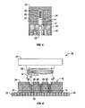
- the present disclosure relates to a microporation device 10.
- the microporation device 10 relates to a method disclosed in International PCT Patent Application No. PCT/US05/19035 to Prausnitz , et al., with an international filing date of May 31, 2005.
- the microporation device 10 is configured to mechanically advance an active agent into a barrier 12 such as mammalian skin through the stratum corneum, viable epidermis and/or the dermis, or alternatively extract a material from the barrier 12.
- the viable or remaining epidermis of the barrier 12 lies below the stratum corneum.
- This viable or remaining epidermis layer of the barrier 12 is about ten times as thick as the stratum corneum; however, diffusion is much faster due to the greater degree of hydration in the living cells of the viable or remaining epidermis.
- the viable or remaining epidermis contains Langerhans' cells, which function as antigen-presenting cells to the immune system.
- the epidermis includes four histologically distinct layers which, from the inside to the outside, are the stratum germinativum, stratum spinosum, stratum granulosum, and the stratum corneum.
- the viable or remaining epidermis is meant to describe the underlying layers excluding the stratum corneum.
- the stratum corneum includes anucleated or dead cells and is the barrier to the delivery of an active agent.
- the microporation device 10 is configured to operatively couple to one or more microprocessors 70 and includes one or more micro-heaters 16 each having a tip end 18 and a base 20.
- the tip end 18 is intended to contact the barrier 12 and be opposite the base 20.
- the microporation device 10 has the base 14 of the microporation device 10 being in contact with an insulation material 22 and a transdermal patch 24 having an active agent disposed therein.
- the microporation device 10 may be formed with the micro-heaters 16 made from one or more materials that are capable of being heated and then transferring heat to the surrounding environment.
- This material may be a single type of metal, layers of metal, conductive oxides, conductive polymers, or alloys, that include, but are not limited to, nickel, iron, ferromagnetic materials, copper, NiCu, PdCo, gadolinium-silicon-germanium alloy, aluminum, ceramic materials, electrodeposited materials, vapor deposited materials, gold, platinum, palladium outer layer coating of nickel, nickel iron, or a magnetic stainless steel alloy, indium tin oxide, lanthanum strontium cobalt oxide, and a aluminum doped zinc oxide.
- the micro-heater 16 of the microporation device 10 is a hollow post 30 made from a thermal member with the tip end 18.
- the thermal member forming the post 30 has an interior space 34 and an outer surface 36.
- the interior space has an ablation material 26 that receives energy and undergoes a rapid phase change from one initial state to another second state.
- the phase change may be from a solid to a liquid.
- the phase change may be from a liquid to a gas.
- the phase change of the ablation material 26 may be from a liquid having a first volume to a liquid having a second volume which is greater than the first volume.
- the ablation material 26 may undergo sublimation or a phase change from a solid to a gas.
- the ablation material 26 is ethanol.
- the ethanol is brought to a rapid temperature increase to increase a volume of the ethanol that will cause the ethanol to physically puncture the barrier 12, such as the stratum corneum forming a micropore 28 in the barrier 12 at a desired depth as shown in Fig. 1 .
- the ablation material 26 may be water, or water based solution.
- the ablation material 26 may be solid or a hydrated salt.
- the microporation device 10 further can be open facing the barrier 12 at the tip end 18 or have an insulating member 22 covering the hollow interior space 34 of the post 30.
- the insulating member 22 may be MYLARTM, KAPTONTM (polyimide), polyurethane, liquid crystal polymer, and epoxy or any material that provides thermal, chemical, or electromagnetic insulation, and is generally nonconductive or nonmagnetic.
- the microporation device 10 may have the thermal member of the post 30 in contact with the barrier 12 or not in physical contact with the barrier 12, and instead with the ablation material 26 in contact with the barrier 12.
- the insulating member 22 disposed on the tip end 18 of the thermal member (of the post 30) may be in contact with the barrier 12.
- Various configurations are possible and within the scope of the present disclosure.
- the micro-heaters 16 having posts 30 may be any desired shape specific for the desired application.
- the micro-heaters 16 can be disk-shaped, cone-shaped, donut-shaped, loop-shaped or still other geometry such as orthogonal, and the size of the posts 30 can vary from one micron to hundreds of microns depending on the barrier 12 and the selected ablation material 26.
- the microporation device 10 is typically connected to a power supply 40 and includes a substrate 42 and one or more micro-heaters 16 each having a thermal member in the form of a post 30 and a hollow interior 34 with an insulating material 22.
- An ablation material 26 such as an ethanol is disposed in the interior 34.
- the power supply 40 includes an alternating current energy supply component that is suitable to alter barrier permeability or to form micropores 28 in a barrier 12.
- the microporation device 10 forms micropores 28 that are a sufficient depth through the stratum corneum 44 and through a portion of the epidermis 46 (such as in the case of the skin).
- the micropores 28 may have another depth for when the barrier 12 is a mucous membrane, or an inner covering such as a lining, a membrane or a surface of an organ or organ structure.
- the microporation device 10 may include any number of micro-heaters 16 in combination with the ablation material 26 that increases the permeability of the barrier 12, for example, by forming one or more micropores 28 in the barrier 12. An active agent from the device 10 is then introduced from the substrate 42 as shown in Figs. 3 and 5 .
- the substrate 42 has a compartment or a suitable absorbent patch and the active agent is pumped or diffused through the formed micropores 28 to the mammalian body.
- the second depth "d' " is not exactly twice the depth "d”, and may be any depth known in the art that is simply greater than depth "d”.
- the power supply 40 of the microporation device 10 may include a wireless induction heating device for generating the micropores.
- This power supply component 40 is connected to an AC power source, and has an induction coil 48 which is electromechanically associated with one or more micro-heaters 16.
- the wireless energizing of the magnetic field M is indicated, and the base 14 of the device 10 is connected to the posts 30 that have the insulating material 22 connected thereto.
- the power supply component 40 comprises the coil 48, a radiofrequency generator, an amplifier and a controller (not shown) that are connected to a switch structure for controlling the coil 48. In this manner, AC current is run through the induction coil 48 to produce magnetic field M.
- the power supply components cause the energy to pass through the induction coil 48.
- the induction coil 48 emits the magnetic field "M" to heat the hollow posts 30 (or thermal member forming the posts 30).
- the posts 30 have the ablation material 26 contained therein.
- the micro-heaters 16 are heated to a desired temperature to create the micropores 28 in the barrier 12. These temperatures range from a cooled temperature, ambient temperature or room temperature to about 90 degrees Centigrade. In another embodiment, the temperature may be over about 400 degrees Centigrade while the barrier 12 is sufficiently not in contact with the micro-heaters 16 to not be heated above about 100 degrees Centigrade.
- the temperature of the posts 30 may be over about 400 degrees Centigrade while the barrier 12 is sufficiently insulated with the insulating material 22 so the micro-heaters 16 cannot heat the barrier 12 above about 100 degrees Centigrade.
- the thermal members of posts 30 are heated by inductive heating.
- the thermal members at the tip end 18 of the posts 30 have a diameter of 400 microns and the base diameter 20 of 80 microns with a metal thickness of 50 microns and a total height of 2 mm. The tip diameter has a flat end for receipt of the insulating material 22 and does not have any sharp tip that is sufficient to puncture the barrier 12.
- the posts 30 may be heated by other or alternative heating elements or systems including, ohmic or resistive heating mechanisms disposed proximate or adjacent the micro-heaters 16, microwave energy systems, by passing electrical current through the micro-heater 16, by passing electrical current across the interior space 34 of the micro-heater 16.
- the posts 30 are described as being heated by inductive heating coils.
- the power supply 40 has an input current to the coil of about 1 amp, and the resulting heating power is about 1 Watt, and 8 Watts at 200 kHz, and 2 MHz, respectively.
- the microporation device 10 of the present disclosure occurs advantageously in two or more discrete stages. The device 10 uses the multiple stages in order to create relatively deep and narrow entry into the barrier 12 and internal disruption of the barrier 12 such as the stratum corneum.
- the microporation device 10 commences operation with a first disruptive event.
- the first disruptive event may be from one or more different microporation events that relate to puncturing the stratum corneum.
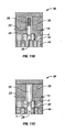
- the activation of the first disruptive event as discussed above is shown in Fig. 6 .
- Fig. 7 shows the microporation device 10 in the initial first disruptive event.
- the microporation device 10 includes power supply 40 with inductive coil 48 operatively connected to the radiofrequency generator.
- the microporation device 10 includes a number of hollow posts 30 formed in an array along the barrier 12 (e.g., 20 x 20 arranged in a generally orthogonal manner) with each of the posts 30 having the ablation material 26 disposed in the interior 34 of the post 30.
- the hollow posts 30 have the liquid ethanol being disposed therein.
- the hollow posts 30 also have the insulating material 22 with a thickness being disposed at or adjacent to the tip end 18 of the hollow posts 30.
- the inductive coil 48 upon being energized with current, heats the hollow posts 30 in a rapid manner.
- the hollow posts 30 reach a temperature of about 400 degrees Centigrade which causes the ethanol to rapidly increase in volume and move into and puncture the barrier 12 as shown.
- Fig. 7 shows the creation of the initial micropore 28.
- a rapid increase of the volume of the ethanol or other ablation material 26 causes the ethanol to increase in volume and expand outward from the hollow post 30 in a direction toward the barrier 12.
- the ablation material 26 will contact the barrier 12 forming the micropore while the microporation device 10 has sufficient insulation 22 in order to keep the temperature of the barrier 12 under about 100 degrees Centigrade at all times.
- the thermal members at the tip end 18 of the posts 30 do not thermally induce the ablation of the barrier 12.
- the ablation of the barrier 12 is not caused by any thermal conduction between the posts 30 and the barrier 12, and instead the micropore is formed by the ablation material 26 mechanically puncturing the barrier 12.
- depth of the micropore in the barrier has a first depth "d" between about 10 to about 30 micrometers which, preferably, extends through the stratum corneum 44 as shown in Fig. 4 with a diameter of the micropore or region of increased permeability being complementary to that of the hollow post 30 and the thermal member. It is envisioned that for some embodiments and for the application of some therapeutic agents this depth "d" is sufficient such that the transdermal patch 24 may contain a therapeutic agent which can be introduced through the micropore 28 having the depth "d". However, for other embodiments introducing other therapeutic agents, a depth greater than about 10 to about 30 micrometers is desired.
- the references to "diameter" for the micropore 28 is not limiting and that other non-circular, non-cylindrical or non-tubular micropores 28 may be formed and are within the scope of the present disclosure.
- the initial micropore formed may include more than one pathway through the stratum corneum 44 and collectively these pathways are considered a micropore 28 embodied in an indistinct shape.
- the disruptive event or mechanical puncturing may include any event that provides for a lipid bilayer disruption or a disorganization of the lipid bi-structure of a layer of the viable epidermis.
- the so-called disruptive event may also include any indiscriminate separation of the region of the viable epidermis to create a pathway to introduce an agent or for fluid extraction.
- Various micropore 28 configurations are possible.
- Fig. 8 shows the microporation device 10 in the second stage.
- the microporation device 10 enlarges the depth "d" of the initial depth to a second depth "d' " greater than the first depth "d” in order to provide for a narrower deeper micropore 28 relative to the prior art.
- the mechanism for enlarging the depth "d" of the micropore 28 may include a thermally activated device, a mechanically-activated device or a chemically-activated device.
- the diameter of the micropore remains substantially the same.
- the second event expands the depth of penetration of the micropore 28 beyond the stratum corneum 44 to an enhanced depth "d' ", e.g., the second event allows fluid communication into viable epidermis layer 46 (or a layer beyond the stratum corneum 44 as shown in Fig. 5 ).
- the second depth "d'" of the micropore 28 after the second stage is greater than about 30 micrometers.
- the second depth "d' " of the micropore 28 after the second stage is greater than about 40 micrometers.
- the second depth "d' " after the second stage is in a range that includes about 40 micrometers to about 60 micrometers.
- the second depth "d' " is greater than about 60 micrometers.
- the second depth "d' " after the second stage is substantially the same as the initial depth “d” and is greater than about 30 micrometers with the second event producing an improvement in at least one relevant physiological property of the micropore.
- the second depth "d'” can have any depth that is dependent upon a number of factors including the specific active agent that is desired to be introduced into the body, the ablation material 26, the configuration of the post 30, and the energy supplied from the power supply 40.
- Fig. 5 shows the second stage of the microporation device with the second depth "d' " of the micropore 28 being in the viable epidermis 46 beyond the stratum corneum layer 44.
- the second microporation event is an event that provides energy in order to disrupt the viable epidermis 46 beyond the stratum corneum layer 44 without excessively damaging or excessively enlarging the diameter of the initial micropore 28 of Fig. 7 beyond a predetermined limit.
- the inductive heating coil 48 may further heat the ablation material 26 in order to further expand the ablation material 26 and further mechanically advance the ablation material 26 into the micropore 28 thereby increasing the depth "d' " of the micropore beyond the stratum corneum 44 and/or for producing an improvement in at least one relevant physiological property of the micropore 28.
- the post 30 may include a first ablation material suitable 26 for forming the micropore 28 with the depth "d” and then a second ablation material 26' suitable for forming the enhanced or second depth "d' " and/or for producing an improvement in at least one relevant physiological property of the micropore 28.
- the first and the second ablation materials 26, 26' may both be disposed in the hollow post 30 of the microporation device 10, e.g., in a layered fashion
- the microporation device 10 also may further heat the ablation material 26 to provoke an immune system response from the cells surrounding the micropore 28.
- the ablation material 26, itself, once released into the micropore 28 may provoke the immune system response.
- the thermal energy E or the ablation material 26 may rupture cells and spill out the contents of the cells into the surrounding areas to provoke an immune response. It has been observed that thermal energy E or the ablation material 26, once imparted to the cells of the viable epidermis 46 and/or the stratum corneum 44 after the formation of the micropore 28, are sufficient to displace proteins normally found inside cells creating extra cellular proteins. Once the extra cellular proteins are displaced in the surrounding areas, the extra cellular proteins will activate the immune system.
- heat shock proteins The specific proteins that activate an immune system response are known to those skilled in the art as so-called "heat shock proteins". These heat shock proteins, which are bound to various peptides, perform functions in various intra-cellular processes during non-stressful conditions. Typically, the production of high levels of heat shock proteins occurs when cells are exposed to environmental stress conditions which may include infection, inflammation, toxins, adverse heat or cold, hypoxia or any condition that may contribute to or exacerbate cell death. In one envisioned embodiment of the present disclosure, the release of heat shock proteins concomitant with pathogens or infectious agents can promote the activation of innate and adaptive immunity.
- the secondary disruptive event may be attributed to an enlargement of the micropore 28 and/or produce an improvement in at least one relevant physiological property of the micropore 28 from a chemical agent 50 or substance that is different from, or the same as, the ablation material 26.
- the chemical agent 50 can be introduced after the formation of the micropore 28 from the hollow post 30, or subsequently after the formation of the micropore 28.
- the chemical agent 50 may be introduced from the substrate 42, the hollow post 30, or an absorbent layer being disposed closely adjacent to the therapeutic agent, on the patch 24 or from another separate location relative to the microporation device 10.
- the chemical agent 50 may be introduced or moved from a first initial location and through the micropore 28.
- the chemical agent 50 can be an organic compound or an inorganic compound that is the same as or different from the ablation material 26.
- the chemical agent 50 may be an organic acid or non-toxic corrosive substance, among many other substances, which undergoes a chemical and/or physiological reaction with the stratum corneum 44 and/or the viable epidermis 46 in order to porate the stratum corneum 44 and viable epidermis 46 to the second depth "d' " and/or produce an improvement in at least one relevant physiological property of the micropore in the second stage.
- the chemical agent 50 may simply disrupt the stratum corneum 44 or the viable epidermis 46 to allow the active agent to enter the viable epidermis 46.
- Some other examples of the chemical agent 50 may include any organic or inorganic compound that can react with, provide a catalytic reaction with, or promote diffusion of the active agent into the micropore 28 and into the viable epidermis 46.
- the chemical agent 50 can be ethanol, or another cell toxin, such as, trace metals, or arsenic.
- the chemical agent 50 can be any substance that places stress on the cells and regulates when the cells will rupture or spill out contents of the cell to provoke an immune response.
- the chemical agent 50 can be any substance that deprives the cells from oxygen to provoke an immune response, or any material that can promote high levels of heat shock proteins to be released from the cells to provoke the immune response.
- the chemical agent 50 can be released at a depth where Langerhans cells are present in the body.
- the secondary disruptive event may be thermal energy E from the inductive coil 48 and or the hollow post 30 after the expansion of the ablation material 28.
- the thermal energy E can be introduced from the hollow post 30 after the formation of the micropore 28 where the hollow post 30 would impart a quantity of thermal energy E from the hollow post 30 and into the micropore 28 for increasing the depth "d' " of the micropore 28 and/or for producing an improvement in at least one relevant physiological property of the micropore.
- the thermal energy E may be introduced from another location exclusive from the hollow post 30 such as from another coil or another discrete heating device.
- the thermal energy E may be introduced from the separate heating device and transferred from conduction or convection (from contact with the source) from a first initial location and through the micropore 28.
- the thermal energy E may be directly applied to the micropore 28 in order to increase a depth "d" of the micropore or the thermal energy E can be transferred to the ablation material 28 (in the second stage), or another organic compound or inorganic compound that is the same as or different from the ablation material 28 and that is non-toxic.
- the second heated material may be sequentially introduced into the micropore 28.
- the thermal energy E that is directly or indirectly applied to the micropore 28 contacts the surrounding lateral surfaces of the stratum corneum 44 and/or the viable epidermis 46 to enlarge the depth "d" on in order to porate to the second depth "d' " in the second stage.
- the thermal energy E can simply disrupt the stratum corneum 44, the viable epidermis 46, or other cells to assist the active agent entering the viable epidermis 46 at an increased rate of diffusion.
- Some examples may include heating the surrounding lateral surface to temperatures in excess of about 100 degrees Celsius in order to ablate and increase the depth of the micropore 28 to the second depth "d' ".
- Various other temperature gradients are possible and within the scope of the present disclosure.
- the secondary disruptive event may be thermal energy E from the inductive coil 48 and or the hollow post 30 after the rapid expansion of the ablation material 26 whereas the temperature increase is significantly less than about 100 degrees Celsius.
- the temperature is not high enough to ablate the tissue, but will promote an increase immune response.
- the thermal energy E can be introduced from the hollow post 30 after the formation of the micropore 28 where the hollow post 30 would impart a quantity of thermal energy from the hollow post 30 into the micropore 28, but not for increasing the depth of the micropore 28, and only for releasing proteins from the surrounding cells of the surrounding tissue of the micropore 28.
- thermal energy E as well as other environmental stress conditions, once imparted to the cells of the viable epidermis 46 and/or the stratum corneum 44 after the formation of the micropore 28, is sufficient to displace proteins normally found inside cells creating extra cellular proteins.
- the proteins once displaced will activate the immune system.
- the proteins thus provoke an immune response in that these proteins with their peptide complexes are detected by circulating immune system cells called antigen presenting cells.
- antigen presenting cells These proteins in the relevant cells of the viable epidermis and the stratum corneum that are displaced are called "heat shock" proteins or stress proteins.
- the antigen presenting cells of the lymphatic system Once the antigen presenting cells of the lymphatic system haven taken in the heat shock proteins complexes, they travel to the lymph nodes and an immune response is stimulated that can facilitate introducing the active agent from the patch 24 or compartment.
- Such stimulation of the immune system may include stimulation of white blood cells that can include lymphocytes, monocytes, neutrophils, eosinophils, basophils, or any combination thereof.
- toxins or ultraviolet light may be released or emitted into the micropore 28 to kill or damage a predetermined number of cells to provoke the immune response.
- the thermal energy E may be introduced from the hollow posts 30 and subsequent to the formation of the micropore 28.
- the thermal energy E may be introduced for a predetermined period of time or in a cycling arrangement that has a suitable maximum temperature to displace the proteins.
- the microporation device 10 may further comprise an additional heating device such as a heating coil that is located at another location exclusive from the hollow posts such as closely adjacent the induction coil 48, the substrate 42 or near the active agent in the patch 24.
- the thermal energy E to displace the proteins may be introduced from the separate heating device and transferred from conduction with direct contact on the micropore 28 or convection from a first initial location and through the air, liquid or gas that surrounds micropore 28.
- the thermal energy E has a suitable maximum temperature to displace the proteins.
- the thermal energy E can be transferred to the ablation material 26, or another non-toxic organic compound or inorganic compound that is the same as or different from the ablation material 26 that is introduced into the micropore 28.
- the thermal energy E to displace the cellular proteins contacts the surrounding lateral tissue surfaces of the stratum corneum 44 and/or the viable epidermis 46.
- the energy E displaces at least some proteins.
- the displacement is of a magnitude in order to stimulate the immune system response in the second stage.
- the microporation device 10 may include a second stage that includes a combination of disruptive events to increase the depth "d" of the micropore to the second depth "d' " and/or produce an improvement in at least one relevant physiological property of the micropore 28.
- the micropore 28 may be formed at the first stage.
- a combination of chemical, thermal and/or mechanical disruptive events can increase the depth of the micropore from the first depth 'd" to the second depth "d' " and/or produce an improvement in at least one relevant physiological property of the micropore 28.
- the second stage may include imparting thermal energy E to the ablation material 26 to further mechanically increase the depth of the micropore from the first depth "d" to the second depth "d' ".
- the microporation device 10 may then heat (e.g., by an inductive heating system, microwave heating system, ohmic or resistive heating systems or electrical system) the hollow posts 30 as shown in Fig. 10 so the hollow posts 30 impart thermal energy E to the micropore 28 assist the mechanical disruptive event from the first depth "d" to the second depth "d' "and/or produce an improvement in at least one relevant physiological property of the micropore 28.
- heat e.g., by an inductive heating system, microwave heating system, ohmic or resistive heating systems or electrical system
- the micropore 28 may be formed at the first stage.
- the second stage may include imparting thermal energy E to the ablation material 26 to further ablate the tissue of the stratum corneum 44 and to increase the depth of the micropore 28 from the first depth "d" to the second depth "d' "and thereafter, the microporation device 10 may then introduce a chemical agent 50 as shown in Fig. 9 to react with tissue 44, 46, and increase the depth of the micropore from the first depth "d" to the second depth "d' "and/or produce an improvement in at least one relevant physiological property of the micropore 28.
- the second stage may include imparting thermal energy E to the ablation material 26 to further ablate the tissue of the stratum corneum 44 to increase the depth of the micropore 28 from the first depth "d" to the second depth "d' ". Thereafter, the microporation device 10 may then transfer thermal energy E at a temperature that is insufficient to ablate the tissue, but sufficient to displace the cellular proteins to initiate an immune response and to assist with introducing the active agent from the device 10 to the body.
- the second stage may include plural disruptive events.
- the microporation device 10 may impart thermal energy E (as shown in Fig. 10 ) to the ablation material 26 to further ablate the tissue of the stratum corneum 44 to increase the depth of the micropore from the first depth "d" to the second depth "d' ", then introduce a chemical agent 50 (as shown in Fig. 9 ) to assist with increasing the depth of the micropore 28 from the depth "d" to the second depth "d' " (not shown) and further the microporation device 10 may then transfer thermal energy E at a temperature that is sufficient to ablate the tissue 44, 46 and/or produce an improvement in at least one relevant physiological property of the micropore 28.
- depth d is less than the second depth d' and the second depth d' is also less than the third depth d".
- any combination of plural disruptive events may be used with the microporation device 10 of the present disclosure that are sufficient to ablate, enlarge the micropore 28 or displace the cellular proteins to initiate an immune response and/or assist with introducing the active agent from the device 10 to the body at a greater flow rate.
- the micropore 28 may be formed from a number of events to achieve a predetermined depth.
- the microporation device 10 has a substrate 42, and a layer 24 for containing the active agent, and an inductive coil 48 connected to the generator (not shown).
- the microporation device 10 also has a number of hollow posts 30. Referring to an enlarged view shown as Fig. 11A , each of the hollow posts 30 has a plurality of ablation materials 26, 26' being disposed therein. Each of the ablation materials 26, 26' has a predetermined rate of volume expansion relative to the desired microporation stage.
- the hollow post 30 has a first ablation material 26 that will rapidly expand at a first temperature T.
- the hollow post 30 also has a second ablation material 26' that will rapidly expand at a second temperature T' that is greater than the first temperature T.
- the first ablation material 26 will rapidly expand and form the micropore having the first depth "d".
- the second ablation material 26' being heated to a first temperature T will remain dormant and in an initial phase.
- the second ablation material 26' may remain outside the micropore 28 for a period of time, or alternatively may enter the micropore 28.
- the temperature of the hollow posts 30 increases from being heated by the inductive heating, the temperature of the second ablation material will rise from the first temperature T to the second temperature T'.
- the first ablation material 26 and the second ablation material 26' may be two completely different inorganic or organic materials that are non-toxic or the second ablation material 26' may be a derivation of the ablation material 26.
- the first ablation material 26 may be an ethanol and the second ablation material may be an ethanol with a number of molecules or a compound that contributes with the later disruption.
- Various configurations are possible and within the present disclosure.
- the second ablation material 26' upon reaching, the second temperature T', the second ablation material 26' will undergo a volumetric increase or phase change from the initial phase to the second phase. This will cause the second ablation material 26' to mechanically increase the depth of the micropore from the initial depth "d° to a second depth "d' " with the second depth "d' " being greater than the depth "d” for a narrower deeper micropore 28.
- the second ablation material 26' may not rapidly change in volume.
- the second ablation material 26' may instead chemically react with the surrounding lateral tissue of the micropore T (shown In Fig. 11 C) to assist with the material 26' chemically reacting with the stratum corneum 42 and/or the viable epidermis 44 in order to increase the micropore 28 from the initial depth "d" to a second depth "d' " and/or produce an improvement in at least one relevant physiological property of the micropore 28.
- the second ablation material 26' may be any material for enlarging to the second depth "d' " with the second depth "d' " being greater than the depth "d” for a narrower deeper micropore 28.
- the microporation device 10 may further create an initial micropore 28 for fluid extraction rather than introducing agents into the micropore 28.
- the microporation device 10 may cause plural disruptive events through the stratum corneum 44 and remaining epidermis 46 as discussed above.
- the microporation device 10 increases a depth of the micropore 28 for increased fluid extraction from the remaining viable epidermis 46 to readily extract an analyte for testing purposes.
- the microporation device 10 can harvest fluid from the tissue for analyte measurement, ph measurement, glucose measurement, or any other analyte in the mammalian body.
- the microporation device 10 may use a vacuum or other device to create a gradient to extract fluid from the micropore 28.
- the gradient may be a pressure gradient.
- the present disclosure also relates to a method for forming a micropore in a barrier.
- the method includes the initial step of providing at least one micro-heater housing an ablation material disposed therein having a volume.
- the micro-heater is adapted to connect to a power supply component which is configured to supply energy to the micro-heater to activate the ablation material.
- the method also includes the steps of: activating the micro-heater to transfer energy to the ablation material; heating the ablation material to a predetermined temperature sufficient to rapidly increase the volume of the ablation material to form a micropore in tissue; introducing at least one anti-healing agent into the micropore to maintain the diffusivity of the tissue; and activating at least one of the micro-heater and ablation material to implement a subsequent disruptive event.
- the step of introducing at least one anti-healing agent into the micropore to maintain the diffusivity of the tissue may be included before or after the first or activating events to maintain the diffusivity of the tissue.
- Anti-healing agent may include any one or combination of the following substances: sodium chloride, calcium-based salts, anti-coagulating agents such as heparin, ethylenediaminetetraacetic acid (EDTA), citric acid, citrate salts, antiinflammatory substances such as hydrocortisone and combination thereof.
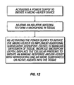
- Fig. 12 shows another envisioned method according to the present disclosure which includes the steps of: activating a power supply to initiate a micro-heater device; heating an ablative material to form a micropore in tissue (e.g., by heating the ablation material to a predetermined temperature sufficient to rapidly increase the volume of the ablation material to form a micropore in tissue); re-activating the power supply to initiate the micro-heater to implement additional subsequent disruptive events to accomplish a particular purpose or to achieve a particular result, maintain diffusivity of tissue, increase micropore depth, displace the cellular proteins to initiate an immune response and/or assist with introducing one or more substances or active agents as described above.
Claims (12)
- Wärmebehandlungseinheit (10) zum Bilden einer Mikropore (28) in einer Barriere, umfassend:wenigstens einen Mikroheizer (16) mit einem Fußende (20) und wenigstens einer darin definierten Säule (30), wobei die Säule (30) ein inneres Volumen zum Aufnehmen eines Ablationsmaterials (26) darin aufweist;eine Stromversorgungskomponente (40) in operativer Verbindung mit dem wenigstens einen Mikroheizer (16), wobei die Stromversorgungskomponente (40) dafür gestaltet ist, den Mikroheizer (16) mit Energie zu versorgen, um das Ablationsmaterial (26) zu aktivieren, so dass sich das Ablationsmaterial (26) in Antwort auf die Energie ausdehnt, um die Barriere (12) mechanisch zu durchstoßen, um eine Mikropore (28) mit einer ersten Tiefe (d) zu erzeugen; wobei die Einheit eine mehrstufige Mikroporationseinheit ist, dadurch gekennzeichnet, dass das innere Volumen der Säule (30) ein chemisches Mittel (50) enthält, das von dem Ablationsmaterial (26) verschieden ist;wobei das chemische Mittel (5) zur chemischen Umsetzung mit der Barriere (12) bereitgestellt ist, um die Mikropore (28) auf eine zweite Tiefe (d') zu vergrößern.
- Wärmebehandlungseinheit (10) gemäß Anspruch 1, wobei das chemische Mittel (50) dafür ausgelegt ist, durch die Vergrößerung der Tiefe der Mikropore (28) auf die zweite Tiefe (d') eine Gewebeantwort anzuregen.
- Wärmebehandlungseinheit (10) gemäß einem der vorstehenden Ansprüche, wobei die wenigstens eine Säule (30) eine Vielzahl verschiedener Materialien enthält, von denen jedes eine andere Wärmeleitfähigkeit aufweist, die das Ablationsmaterial (26) bei verschiedenen Stadien aktivieren, um die Tiefe der Mikropore bei entsprechend verschiedenen Stadien zu erhöhen.
- Wärmebehandlungseinheit (10) gemäß einem der vorstehenden Ansprüche, wobei das Ablationsmaterial (26) Ethanol enthält und wobei der Mikroheizer (16) ein Isolatormaterial (22) enthält, das übermäßiges Erhitzen der Barriere (12) während der Aktivierung des Ablationsmaterials (26) verhindert.
- Wärmebehandlungseinheit (10) gemäß Anspruch 4, wobei das Isolatormaterial (22) verhindert, dass die Barriere (12) etwa einhundert Grad Celsius erreicht.
- Wärmebehandlungseinheit (10) gemäß einem der vorstehenden Ansprüche, wobei die erste Tiefe (d) etwa zehn Mikrometer bis etwa dreißig Mikrometer beträgt und wobei die zweite Tiefe (d') mehr als etwa dreißig Mikrometer beträgt.
- Wärmebehandlungseinheit (10) gemäß einem der vorstehenden Ansprüche, wobei die Barriere Haut ist und wobei die erste Tiefe (d) im Bereich von etwa zehn Mikrometer bis etwa dreißig Mikrometer liegt und wobei die zweite Tiefe (d') ausreicht, um sich mehr als dreißig Mikrometer in die lebende Epidermis zu erstrecken.
- Wärmebehandlungseinheit (10) gemäß einem der vorstehenden Ansprüche, wobei das chemische Mittel (50) wenigstens eine Zelle der Epidermis des Gewebes, das die Mikropore (28) umgibt, aufbricht, wobei das Aufbrechen eine Immunantwort des Gewebes anregt.
- Wärmebehandlungseinheit (10) gemäß einem der vorstehenden Ansprüche, wobei das chemische Mittel (50) wenigstens eine Zelle der Epidermis des Gewebes, das die Mikropore (28) umgibt, aufbricht, indem es in der Zelle vorhandene Proteine verdrängt.
- Wärmebehandlungseinheit (10) gemäß Anspruch 9, wobei die Proteine Hitzeschockproteine sind.
- Wärmebehandlungseinheit (10) gemäß einem der vorstehenden Ansprüche, wobei das Ablationsmaterial (26) Ethanol enthält.
- Wärmebehandlungseinheit (10) gemäß einem der vorstehenden Ansprüche, wobei der Mikroheizer (16) wenigstens eine Zelle der Barriere (12), die die Mikropore (28) umgibt, aufbricht, indem sie Wärmeenergie in die Mikropore (28) überträgt, wobei das Aufbrechen eine Immunantwort bewirkt.
Applications Claiming Priority (2)
| Application Number | Priority Date | Filing Date | Title |
|---|---|---|---|
| US79497906P | 2006-04-26 | 2006-04-26 | |
| PCT/US2007/010185 WO2007127339A2 (en) | 2006-04-26 | 2007-04-26 | Multi-stage microporation device |
Publications (3)
| Publication Number | Publication Date |
|---|---|
| EP2010276A2 EP2010276A2 (de) | 2009-01-07 |
| EP2010276A4 EP2010276A4 (de) | 2010-11-03 |
| EP2010276B1 true EP2010276B1 (de) | 2014-01-22 |
Family
ID=38656200
Family Applications (1)
| Application Number | Title | Priority Date | Filing Date |
|---|---|---|---|
| EP07756084.5A Not-in-force EP2010276B1 (de) | 2006-04-26 | 2007-04-26 | Mehrfachmodus-mikroporationsvorrichtung |
Country Status (3)
| Country | Link |
|---|---|
| US (1) | US20080234626A1 (de) |
| EP (1) | EP2010276B1 (de) |
| WO (1) | WO2007127339A2 (de) |
Families Citing this family (9)
| Publication number | Priority date | Publication date | Assignee | Title |
|---|---|---|---|---|
| US8048089B2 (en) | 2005-12-30 | 2011-11-01 | Edge Systems Corporation | Apparatus and methods for treating the skin |
| JP5508285B2 (ja) | 2008-01-04 | 2014-05-28 | エッジ システムズ コーポレーション | 皮膚を治療するための装置および方法 |
| JP2011132208A (ja) | 2009-11-25 | 2011-07-07 | Dainichiseika Color & Chem Mfg Co Ltd | 5員環環状カーボネートポリシロキサン化合物およびその製造方法 |
| US9993664B2 (en) * | 2010-03-03 | 2018-06-12 | Lumenis Ltd. | System and methods of tissue microablation using fractional treatment patterns |
| EP2967633B1 (de) | 2013-03-15 | 2018-04-25 | Edge Systems LLC | Vorrichtungen zur hautbehandlung |
| EP4324414A2 (de) | 2014-12-23 | 2024-02-21 | HydraFacial LLC | Vorrichtungen und verfahren zur hautbehandlung mit einem rollball oder einem dochtelement |
| DE102015016822B4 (de) | 2015-12-25 | 2023-01-05 | Azur Space Solar Power Gmbh | Stapelförmige Mehrfach-Solarzelle |
| DE102016214783A1 (de) * | 2016-08-09 | 2018-02-15 | Siemens Aktiengesellschaft | Sprungantrieb sowie Schalteinrichtung mit Sprungantrieb |
| USD1016615S1 (en) | 2021-09-10 | 2024-03-05 | Hydrafacial Llc | Container for a skin treatment device |
Family Cites Families (83)
| Publication number | Priority date | Publication date | Assignee | Title |
|---|---|---|---|---|
| US1404406A (en) * | 1921-04-22 | 1922-01-24 | George W Prouty | Mechanical movement |
| US3964482A (en) * | 1971-05-17 | 1976-06-22 | Alza Corporation | Drug delivery device |
| US4500724A (en) * | 1983-07-28 | 1985-02-19 | General Electric Company | Method for making alkylhalosilanes |
| SE459662B (sv) * | 1986-03-21 | 1989-07-24 | Pharmacia Ab | Hybrid-dna-molekyl som kodar foer ett protein med samma igg specificitet som protein g, plasmid innehaallande densamma samt foerfarande foer framstaellning av proteinet |
| AU4945490A (en) * | 1989-01-06 | 1990-08-01 | Angioplasty Systems Inc. | Electrosurgical catheter for resolving atherosclerotic plaque |
| US4992723A (en) * | 1989-03-31 | 1991-02-12 | Square D Company | Fault-powered power supply |
| US5019936A (en) * | 1989-03-31 | 1991-05-28 | Square D Company | Voltage-to-frequency squared circuit |
| US5125928A (en) * | 1989-04-13 | 1992-06-30 | Everest Medical Corporation | Ablation catheter with selectively deployable electrodes |
| US5098431A (en) * | 1989-04-13 | 1992-03-24 | Everest Medical Corporation | RF ablation catheter |
| US5411947A (en) * | 1989-06-28 | 1995-05-02 | Vestar, Inc. | Method of converting a drug to an orally available form by covalently bonding a lipid to the drug |
| US5190558A (en) * | 1989-11-08 | 1993-03-02 | Nec Corporation | Method of eliminating stratum corneum from the skin and an instrument to be used therefor |
| US5080660A (en) * | 1990-05-11 | 1992-01-14 | Applied Urology, Inc. | Electrosurgical electrode |
| US5295704A (en) * | 1990-12-06 | 1994-03-22 | Flock Thomas P | Ski binding with knee flex sensor |
| US5383917A (en) * | 1991-07-05 | 1995-01-24 | Jawahar M. Desai | Device and method for multi-phase radio-frequency ablation |
| US5620481A (en) * | 1991-07-05 | 1997-04-15 | Desai; Jawahar M. | Device for multi-phase radio-frequency ablation |
| US5713845A (en) * | 1991-10-29 | 1998-02-03 | Thermolase Corporation | Laser assisted drug delivery |
| US5423803A (en) * | 1991-10-29 | 1995-06-13 | Thermotrex Corporation | Skin surface peeling process using laser |
| US6024733A (en) * | 1995-06-07 | 2000-02-15 | Arthrocare Corporation | System and method for epidermal tissue ablation |
| WO1993017640A1 (en) * | 1992-03-11 | 1993-09-16 | Phillips L Van | Alignment fixture for prosthetic device |
| US5281218A (en) * | 1992-06-05 | 1994-01-25 | Cardiac Pathways Corporation | Catheter having needle electrode for radiofrequency ablation |
| US5766211A (en) * | 1993-02-08 | 1998-06-16 | Wood; Jan | Medical device for allowing insertion and drainage into a body cavity |
| US5427585A (en) * | 1993-03-29 | 1995-06-27 | Bettinger; David S. | On-demand iontophoretic system |
| US5419312A (en) * | 1993-04-20 | 1995-05-30 | Wildflower Communications, Inc. | Multi-function endoscope apparatus |
| US5431649A (en) * | 1993-08-27 | 1995-07-11 | Medtronic, Inc. | Method and apparatus for R-F ablation |
| US6056738A (en) * | 1997-01-31 | 2000-05-02 | Transmedica International, Inc. | Interstitial fluid monitoring |
| US5458140A (en) * | 1993-11-15 | 1995-10-17 | Non-Invasive Monitoring Company (Nimco) | Enhancement of transdermal monitoring applications with ultrasound and chemical enhancers |
| US5885211A (en) * | 1993-11-15 | 1999-03-23 | Spectrix, Inc. | Microporation of human skin for monitoring the concentration of an analyte |
| US5814599A (en) * | 1995-08-04 | 1998-09-29 | Massachusetts Insitiute Of Technology | Transdermal delivery of encapsulated drugs |
| US5609151A (en) * | 1994-09-08 | 1997-03-11 | Medtronic, Inc. | Method for R-F ablation |
| US6032070A (en) * | 1995-06-07 | 2000-02-29 | University Of Arkansas | Method and apparatus for detecting electro-magnetic reflection from biological tissue |
| US6041253A (en) * | 1995-12-18 | 2000-03-21 | Massachusetts Institute Of Technology | Effect of electric field and ultrasound for transdermal drug delivery |
| US20020045890A1 (en) * | 1996-04-24 | 2002-04-18 | The Regents Of The University O F California | Opto-acoustic thrombolysis |
| US6022309A (en) * | 1996-04-24 | 2000-02-08 | The Regents Of The University Of California | Opto-acoustic thrombolysis |
| US5944687A (en) * | 1996-04-24 | 1999-08-31 | The Regents Of The University Of California | Opto-acoustic transducer for medical applications |
| SE9602496D0 (sv) * | 1996-06-20 | 1996-06-20 | Bengt Guss | Method and means for producing a fibrinogen binding protein and its use in biotechnology |
| DE69722414T2 (de) * | 1996-07-03 | 2004-05-19 | Altea Therapeutics Corp. | Mehrfache mechanische mikroperforierung von haut oder schleimhäuten |
| US6027459A (en) * | 1996-12-06 | 2000-02-22 | Abbott Laboratories | Method and apparatus for obtaining blood for diagnostic tests |
| US6063039A (en) * | 1996-12-06 | 2000-05-16 | Abbott Laboratories | Method and apparatus for obtaining blood for diagnostic tests |
| US6527716B1 (en) * | 1997-12-30 | 2003-03-04 | Altea Technologies, Inc. | Microporation of tissue for delivery of bioactive agents |
| US5897494A (en) * | 1997-01-31 | 1999-04-27 | The Board Of Trustees Of The University Of Arkansas | Vibrometer |
| US6027496A (en) * | 1997-03-25 | 2000-02-22 | Abbott Laboratories | Removal of stratum corneum by means of light |
| US6235015B1 (en) * | 1997-05-14 | 2001-05-22 | Applied Optronics Corporation | Method and apparatus for selective hair depilation using a scanned beam of light at 600 to 1000 nm |
| DE69928229T2 (de) * | 1998-02-17 | 2006-08-03 | Abbott Laboratories, Abbott Park | Gerät zum entnehmen und analysieren von interstitieller flüssigkeit |
| US6530915B1 (en) * | 1998-03-06 | 2003-03-11 | Spectrx, Inc. | Photothermal structure for biomedical applications, and method therefor |
| US6173202B1 (en) * | 1998-03-06 | 2001-01-09 | Spectrx, Inc. | Method and apparatus for enhancing flux rates of a fluid in a microporated biological tissue |
| US6022316A (en) * | 1998-03-06 | 2000-02-08 | Spectrx, Inc. | Apparatus and method for electroporation of microporated tissue for enhancing flux rates for monitoring and delivery applications |
| US6353753B1 (en) * | 1998-05-05 | 2002-03-05 | Stephen Thomas Flock | Optical imaging of deep anatomic structures |
| US6569157B1 (en) * | 1998-05-18 | 2003-05-27 | Abbott Laboratories | Removal of stratum corneum by means of light |
| US6352517B1 (en) * | 1998-06-02 | 2002-03-05 | Stephen Thomas Flock | Optical monitor of anatomical movement and uses thereof |
| ATE413899T1 (de) * | 1998-07-14 | 2008-11-15 | Altea Therapeutics Corp | Transdermale transportvorrichtung zum kontrollierten entfernen von biologischen membranen durch pyrotechnische ladung |
| CA2342801A1 (en) * | 1998-09-04 | 2000-03-16 | Powderject Research Limited | Monitoring methods using particle delivery methods |
| US6602678B2 (en) * | 1998-09-04 | 2003-08-05 | Powderject Research Limited | Non- or minimally invasive monitoring methods |
| US6148232A (en) * | 1998-11-09 | 2000-11-14 | Elecsys Ltd. | Transdermal drug delivery and analyte extraction |
| US6708060B1 (en) * | 1998-11-09 | 2004-03-16 | Transpharma Ltd. | Handheld apparatus and method for transdermal drug delivery and analyte extraction |
| US6597946B2 (en) * | 1998-11-09 | 2003-07-22 | Transpharma Ltd. | Electronic card for transdermal drug delivery and analyte extraction |
| US6233269B1 (en) * | 1998-12-16 | 2001-05-15 | Cell Robotics, Inc. | Apparatus and method for protecting components of a light source |
| US6889258B1 (en) * | 1999-03-04 | 2005-05-03 | Webtv Networks, Inc. | Automatic compiling of address filter information |
| US6389313B1 (en) * | 1999-03-26 | 2002-05-14 | Kevin S. Marchitto | Laser probes for drug permeation |
| US6532387B1 (en) * | 1999-03-26 | 2003-03-11 | Kevin S. Marchitto | Catheter for delivering electromagnetic energy for enhanced permeation of substances |
| US6673214B1 (en) * | 1999-04-09 | 2004-01-06 | Rocky Mountain Biosystems, Inc. | Energy enhanced reaction catalysis and uses thereof |
| MXPA01010404A (es) * | 1999-04-16 | 2003-07-21 | Childrens Medical Center | Peptidos moduladores de adhesion y metodos para utilizarlos. |
| WO2000064514A1 (en) * | 1999-04-22 | 2000-11-02 | Gilbert Garitano | Needleless permanent makeup and tattoo device |
| US6689380B1 (en) * | 1999-05-17 | 2004-02-10 | Kevin S. Marchitto | Remote and local controlled delivery of pharmaceutical compounds using electromagnetic energy |
| WO2000074767A2 (en) * | 1999-06-08 | 2000-12-14 | Altea Technologies, Inc. | Apparatus for microporation of biological membranes using thin film tissue interface devices, and method therefor |
| US6685699B1 (en) * | 1999-06-09 | 2004-02-03 | Spectrx, Inc. | Self-removing energy absorbing structure for thermal tissue ablation |
| US20030078499A1 (en) * | 1999-08-12 | 2003-04-24 | Eppstein Jonathan A. | Microporation of tissue for delivery of bioactive agents |
| US7133717B2 (en) * | 1999-08-25 | 2006-11-07 | Johnson & Johnson Consumer Companies, Inc. | Tissue electroperforation for enhanced drug delivery and diagnostic sampling |
| FR2799374B1 (fr) * | 1999-10-08 | 2001-12-07 | Cross Site Technologies | Seringue sans aiguille munie d'un systeme de declenchement par friction |
| FR2807946B1 (fr) * | 2000-04-19 | 2002-06-07 | Poudres & Explosifs Ste Nale | Seringue sans aiguille fonctionnant avec un chargement pyrotechnique bicomposition |
| AU2001261160A1 (en) * | 2000-05-03 | 2001-11-12 | Stephen T Flock | Prosthesis and method of making |
| US6562004B1 (en) * | 2000-06-05 | 2003-05-13 | The Massachusetts General Hospital | Transdermal delivery |
| US6706032B2 (en) * | 2000-06-08 | 2004-03-16 | Massachusetts Institute Of Technology | Localized molecular and ionic transport to and from tissues |
| US6989075B1 (en) * | 2000-11-03 | 2006-01-24 | The Procter & Gamble Company | Tension activatable substrate |
| US6554827B2 (en) * | 2000-12-11 | 2003-04-29 | Scimed Life Systems, Inc. | Radio frequency ablation system |
| US6503209B2 (en) * | 2001-05-18 | 2003-01-07 | Said I. Hakky | Non-invasive focused energy blood withdrawal and analysis system |
| US6507177B2 (en) * | 2001-06-05 | 2003-01-14 | Alcoa Fujikura Gesellschaft Mit Beschraenkter Haftung | Control circuit for the power controlled operation of a load |
| FR2827377B1 (fr) * | 2001-07-13 | 2003-12-05 | Poudres & Explosifs Ste Nale | Dispositif d'allumage pour microcharges pyrotechniques |
| US6813289B2 (en) * | 2001-07-25 | 2004-11-02 | Innotech, Usa, Inc. | Portable laser device |
| US20040030325A1 (en) * | 2001-12-05 | 2004-02-12 | Nicholas Cahir | Removable attachments for laser emitting devices |
| CA2478822C (en) * | 2002-03-11 | 2016-07-12 | Altea Therapeutics Corporation | Transdermal drug delivery patch system, method of making same and method of using same |
| US6845284B2 (en) * | 2003-02-11 | 2005-01-18 | Sara Lee Corporation | Methods and systems for designing circularly knitted garments |
| US8016811B2 (en) * | 2003-10-24 | 2011-09-13 | Altea Therapeutics Corporation | Method for transdermal delivery of permeant substances |
| US8690865B2 (en) * | 2004-05-28 | 2014-04-08 | Georgia Tech Research Corporation | Methods and devices for thermal treatment |
-
2007
- 2007-04-26 EP EP07756084.5A patent/EP2010276B1/de not_active Not-in-force
- 2007-04-26 WO PCT/US2007/010185 patent/WO2007127339A2/en active Application Filing
- 2007-04-26 US US11/796,107 patent/US20080234626A1/en not_active Abandoned
Also Published As
| Publication number | Publication date |
|---|---|
| WO2007127339A3 (en) | 2008-03-27 |
| EP2010276A4 (de) | 2010-11-03 |
| US20080234626A1 (en) | 2008-09-25 |
| EP2010276A2 (de) | 2009-01-07 |
| WO2007127339A2 (en) | 2007-11-08 |
Similar Documents
| Publication | Publication Date | Title |
|---|---|---|
| EP2010276B1 (de) | Mehrfachmodus-mikroporationsvorrichtung | |
| EP1189660B1 (de) | Vorrichtung zur mikroporation eines biologischen gewebes mittels einer filmgewebe schnittstellenvorrichtung und verfahren | |
| Daugimont et al. | Hollow microneedle arrays for intradermal drug delivery and DNA electroporation | |
| US8690865B2 (en) | Methods and devices for thermal treatment | |
| EP1955731B1 (de) | Anwendung mit monopolarem und bipolarem Strom zur transdermalen Wirkstoffverabreichung und Analytextraktion | |
| US6022316A (en) | Apparatus and method for electroporation of microporated tissue for enhancing flux rates for monitoring and delivery applications | |
| JP4700283B2 (ja) | 経皮薬物送達パッチシステム、このシステムを作製する方法およびこのシステムを使用する方法 | |
| US20090318846A1 (en) | Methods and apparatus for surface ablation | |
| JP2007516792A (ja) | 不可逆的電気穿孔による組織アブレーション | |
| WO2006124639A1 (en) | Permeabilization of biological membranes | |
| KR20160093658A (ko) | 비열 플라즈마를 사용한 dna 백신의 경피 전달 | |
| CN102631243B (zh) | 电磁热疗法的治疗器具 | |
| WO2009005568A1 (en) | Methods and apparatus for surface ablation | |
| Park et al. | Wireless thermal micro-ablation of skin for transdermal drug delivery | |
| Kurata et al. | Experimental and analytical studies on contact irreversible electroporation for superficial tumor treatment | |
| Rathod et al. | Thermal ablation for transdermal drug delivery | |
| Le | Enhancing the Low-Frequency Induction Heating Effect of Magnetic Composites for Medical Applications |
Legal Events
| Date | Code | Title | Description |
|---|---|---|---|
| PUAI | Public reference made under article 153(3) epc to a published international application that has entered the european phase |
Free format text: ORIGINAL CODE: 0009012 |
|
| 17P | Request for examination filed |
Effective date: 20080925 |
|
| AK | Designated contracting states |
Kind code of ref document: A2 Designated state(s): AT BE BG CH CY CZ DE DK EE ES FI FR GB GR HU IE IS IT LI LT LU LV MC MT NL PL PT RO SE SI SK TR |
|
| AX | Request for extension of the european patent |
Extension state: AL BA HR MK RS |
|
| DAX | Request for extension of the european patent (deleted) | ||
| A4 | Supplementary search report drawn up and despatched |
Effective date: 20101006 |
|
| RAP1 | Party data changed (applicant data changed or rights of an application transferred) |
Owner name: COVIDIEN LP |
|
| GRAP | Despatch of communication of intention to grant a patent |
Free format text: ORIGINAL CODE: EPIDOSNIGR1 |
|
| INTG | Intention to grant announced |
Effective date: 20130821 |
|
| GRAS | Grant fee paid |
Free format text: ORIGINAL CODE: EPIDOSNIGR3 |
|
| GRAA | (expected) grant |
Free format text: ORIGINAL CODE: 0009210 |
|
| AK | Designated contracting states |
Kind code of ref document: B1 Designated state(s): AT BE BG CH CY CZ DE DK EE ES FI FR GB GR HU IE IS IT LI LT LU LV MC MT NL PL PT RO SE SI SK TR |
|
| REG | Reference to a national code |
Ref country code: GB Ref legal event code: FG4D |
|
| REG | Reference to a national code |
Ref country code: CH Ref legal event code: EP |
|
| REG | Reference to a national code |
Ref country code: AT Ref legal event code: REF Ref document number: 650483 Country of ref document: AT Kind code of ref document: T Effective date: 20140215 |
|
| REG | Reference to a national code |
Ref country code: IE Ref legal event code: FG4D |
|
| REG | Reference to a national code |
Ref country code: DE Ref legal event code: R096 Ref document number: 602007034917 Country of ref document: DE Effective date: 20140306 |
|
| REG | Reference to a national code |
Ref country code: NL Ref legal event code: VDEP Effective date: 20140122 |
|
| REG | Reference to a national code |
Ref country code: AT Ref legal event code: MK05 Ref document number: 650483 Country of ref document: AT Kind code of ref document: T Effective date: 20140122 |
|
| REG | Reference to a national code |
Ref country code: LT Ref legal event code: MG4D |
|
| PG25 | Lapsed in a contracting state [announced via postgrant information from national office to epo] |
Ref country code: LT Free format text: LAPSE BECAUSE OF FAILURE TO SUBMIT A TRANSLATION OF THE DESCRIPTION OR TO PAY THE FEE WITHIN THE PRESCRIBED TIME-LIMIT Effective date: 20140122 Ref country code: IS Free format text: LAPSE BECAUSE OF FAILURE TO SUBMIT A TRANSLATION OF THE DESCRIPTION OR TO PAY THE FEE WITHIN THE PRESCRIBED TIME-LIMIT Effective date: 20140522 |
|
| PG25 | Lapsed in a contracting state [announced via postgrant information from national office to epo] |
Ref country code: FI Free format text: LAPSE BECAUSE OF FAILURE TO SUBMIT A TRANSLATION OF THE DESCRIPTION OR TO PAY THE FEE WITHIN THE PRESCRIBED TIME-LIMIT Effective date: 20140122 Ref country code: AT Free format text: LAPSE BECAUSE OF FAILURE TO SUBMIT A TRANSLATION OF THE DESCRIPTION OR TO PAY THE FEE WITHIN THE PRESCRIBED TIME-LIMIT Effective date: 20140122 Ref country code: ES Free format text: LAPSE BECAUSE OF FAILURE TO SUBMIT A TRANSLATION OF THE DESCRIPTION OR TO PAY THE FEE WITHIN THE PRESCRIBED TIME-LIMIT Effective date: 20140122 Ref country code: PT Free format text: LAPSE BECAUSE OF FAILURE TO SUBMIT A TRANSLATION OF THE DESCRIPTION OR TO PAY THE FEE WITHIN THE PRESCRIBED TIME-LIMIT Effective date: 20140522 Ref country code: NL Free format text: LAPSE BECAUSE OF FAILURE TO SUBMIT A TRANSLATION OF THE DESCRIPTION OR TO PAY THE FEE WITHIN THE PRESCRIBED TIME-LIMIT Effective date: 20140122 Ref country code: SE Free format text: LAPSE BECAUSE OF FAILURE TO SUBMIT A TRANSLATION OF THE DESCRIPTION OR TO PAY THE FEE WITHIN THE PRESCRIBED TIME-LIMIT Effective date: 20140122 Ref country code: CY Free format text: LAPSE BECAUSE OF FAILURE TO SUBMIT A TRANSLATION OF THE DESCRIPTION OR TO PAY THE FEE WITHIN THE PRESCRIBED TIME-LIMIT Effective date: 20140122 |
|
| PG25 | Lapsed in a contracting state [announced via postgrant information from national office to epo] |
Ref country code: LV Free format text: LAPSE BECAUSE OF FAILURE TO SUBMIT A TRANSLATION OF THE DESCRIPTION OR TO PAY THE FEE WITHIN THE PRESCRIBED TIME-LIMIT Effective date: 20140122 Ref country code: BE Free format text: LAPSE BECAUSE OF FAILURE TO SUBMIT A TRANSLATION OF THE DESCRIPTION OR TO PAY THE FEE WITHIN THE PRESCRIBED TIME-LIMIT Effective date: 20140122 |
|
| REG | Reference to a national code |
Ref country code: DE Ref legal event code: R097 Ref document number: 602007034917 Country of ref document: DE |
|
| PG25 | Lapsed in a contracting state [announced via postgrant information from national office to epo] |
Ref country code: EE Free format text: LAPSE BECAUSE OF FAILURE TO SUBMIT A TRANSLATION OF THE DESCRIPTION OR TO PAY THE FEE WITHIN THE PRESCRIBED TIME-LIMIT Effective date: 20140122 Ref country code: CZ Free format text: LAPSE BECAUSE OF FAILURE TO SUBMIT A TRANSLATION OF THE DESCRIPTION OR TO PAY THE FEE WITHIN THE PRESCRIBED TIME-LIMIT Effective date: 20140122 Ref country code: DK Free format text: LAPSE BECAUSE OF FAILURE TO SUBMIT A TRANSLATION OF THE DESCRIPTION OR TO PAY THE FEE WITHIN THE PRESCRIBED TIME-LIMIT Effective date: 20140122 Ref country code: RO Free format text: LAPSE BECAUSE OF FAILURE TO SUBMIT A TRANSLATION OF THE DESCRIPTION OR TO PAY THE FEE WITHIN THE PRESCRIBED TIME-LIMIT Effective date: 20140122 |
|
| REG | Reference to a national code |
Ref country code: DE Ref legal event code: R119 Ref document number: 602007034917 Country of ref document: DE |
|
| PG25 | Lapsed in a contracting state [announced via postgrant information from national office to epo] |
Ref country code: SK Free format text: LAPSE BECAUSE OF FAILURE TO SUBMIT A TRANSLATION OF THE DESCRIPTION OR TO PAY THE FEE WITHIN THE PRESCRIBED TIME-LIMIT Effective date: 20140122 Ref country code: LU Free format text: LAPSE BECAUSE OF FAILURE TO SUBMIT A TRANSLATION OF THE DESCRIPTION OR TO PAY THE FEE WITHIN THE PRESCRIBED TIME-LIMIT Effective date: 20140426 Ref country code: MC Free format text: LAPSE BECAUSE OF FAILURE TO SUBMIT A TRANSLATION OF THE DESCRIPTION OR TO PAY THE FEE WITHIN THE PRESCRIBED TIME-LIMIT Effective date: 20140122 Ref country code: PL Free format text: LAPSE BECAUSE OF FAILURE TO SUBMIT A TRANSLATION OF THE DESCRIPTION OR TO PAY THE FEE WITHIN THE PRESCRIBED TIME-LIMIT Effective date: 20140122 |
|
| PLBE | No opposition filed within time limit |
Free format text: ORIGINAL CODE: 0009261 |
|
| REG | Reference to a national code |
Ref country code: CH Ref legal event code: PL |
|
| STAA | Information on the status of an ep patent application or granted ep patent |
Free format text: STATUS: NO OPPOSITION FILED WITHIN TIME LIMIT |
|
| GBPC | Gb: european patent ceased through non-payment of renewal fee |
Effective date: 20140426 |
|
| 26N | No opposition filed |
Effective date: 20141023 |
|
| REG | Reference to a national code |
Ref country code: DE Ref legal event code: R119 Ref document number: 602007034917 Country of ref document: DE Effective date: 20141101 |
|
| REG | Reference to a national code |
Ref country code: FR Ref legal event code: ST Effective date: 20141231 |
|
| REG | Reference to a national code |
Ref country code: IE Ref legal event code: MM4A |
|
| PG25 | Lapsed in a contracting state [announced via postgrant information from national office to epo] |
Ref country code: GB Free format text: LAPSE BECAUSE OF NON-PAYMENT OF DUE FEES Effective date: 20140426 Ref country code: LI Free format text: LAPSE BECAUSE OF NON-PAYMENT OF DUE FEES Effective date: 20140430 Ref country code: DE Free format text: LAPSE BECAUSE OF NON-PAYMENT OF DUE FEES Effective date: 20141101 Ref country code: CH Free format text: LAPSE BECAUSE OF NON-PAYMENT OF DUE FEES Effective date: 20140430 |
|
| REG | Reference to a national code |
Ref country code: DE Ref legal event code: R097 Ref document number: 602007034917 Country of ref document: DE Effective date: 20141023 |
|
| PG25 | Lapsed in a contracting state [announced via postgrant information from national office to epo] |
Ref country code: FR Free format text: LAPSE BECAUSE OF NON-PAYMENT OF DUE FEES Effective date: 20140430 |
|
| PG25 | Lapsed in a contracting state [announced via postgrant information from national office to epo] |
Ref country code: IE Free format text: LAPSE BECAUSE OF NON-PAYMENT OF DUE FEES Effective date: 20140426 |
|
| PG25 | Lapsed in a contracting state [announced via postgrant information from national office to epo] |
Ref country code: SI Free format text: LAPSE BECAUSE OF FAILURE TO SUBMIT A TRANSLATION OF THE DESCRIPTION OR TO PAY THE FEE WITHIN THE PRESCRIBED TIME-LIMIT Effective date: 20140122 |
|
| PG25 | Lapsed in a contracting state [announced via postgrant information from national office to epo] |
Ref country code: MT Free format text: LAPSE BECAUSE OF FAILURE TO SUBMIT A TRANSLATION OF THE DESCRIPTION OR TO PAY THE FEE WITHIN THE PRESCRIBED TIME-LIMIT Effective date: 20140122 |
|
| PG25 | Lapsed in a contracting state [announced via postgrant information from national office to epo] |
Ref country code: BG Free format text: LAPSE BECAUSE OF FAILURE TO SUBMIT A TRANSLATION OF THE DESCRIPTION OR TO PAY THE FEE WITHIN THE PRESCRIBED TIME-LIMIT Effective date: 20140122 |
|
| PG25 | Lapsed in a contracting state [announced via postgrant information from national office to epo] |
Ref country code: GR Free format text: LAPSE BECAUSE OF FAILURE TO SUBMIT A TRANSLATION OF THE DESCRIPTION OR TO PAY THE FEE WITHIN THE PRESCRIBED TIME-LIMIT Effective date: 20140423 Ref country code: IT Free format text: LAPSE BECAUSE OF FAILURE TO SUBMIT A TRANSLATION OF THE DESCRIPTION OR TO PAY THE FEE WITHIN THE PRESCRIBED TIME-LIMIT Effective date: 20140122 |
|
| PG25 | Lapsed in a contracting state [announced via postgrant information from national office to epo] |
Ref country code: TR Free format text: LAPSE BECAUSE OF FAILURE TO SUBMIT A TRANSLATION OF THE DESCRIPTION OR TO PAY THE FEE WITHIN THE PRESCRIBED TIME-LIMIT Effective date: 20140122 Ref country code: HU Free format text: LAPSE BECAUSE OF FAILURE TO SUBMIT A TRANSLATION OF THE DESCRIPTION OR TO PAY THE FEE WITHIN THE PRESCRIBED TIME-LIMIT; INVALID AB INITIO Effective date: 20070426 |