EP2010258B1 - Dry powder inhaler - Google Patents
Dry powder inhaler Download PDFInfo
- Publication number
- EP2010258B1 EP2010258B1 EP07711576.4A EP07711576A EP2010258B1 EP 2010258 B1 EP2010258 B1 EP 2010258B1 EP 07711576 A EP07711576 A EP 07711576A EP 2010258 B1 EP2010258 B1 EP 2010258B1
- Authority
- EP
- European Patent Office
- Prior art keywords
- capsule
- mouthpiece
- dry
- powder inhaler
- basic housing
- Prior art date
- Legal status (The legal status is an assumption and is not a legal conclusion. Google has not performed a legal analysis and makes no representation as to the accuracy of the status listed.)
- Active
Links
- 229940112141 dry powder inhaler Drugs 0.000 title claims description 20
- 239000002775 capsule Substances 0.000 claims description 106
- 239000000843 powder Substances 0.000 claims description 12
- 238000003780 insertion Methods 0.000 claims description 3
- 230000037431 insertion Effects 0.000 claims description 3
- 238000007373 indentation Methods 0.000 claims 3
- 230000000994 depressogenic effect Effects 0.000 description 2
- 240000001439 Opuntia Species 0.000 description 1
- 235000004727 Opuntia ficus indica Nutrition 0.000 description 1
- 230000001419 dependent effect Effects 0.000 description 1
- 238000006073 displacement reaction Methods 0.000 description 1
- 210000003811 finger Anatomy 0.000 description 1
- 230000004941 influx Effects 0.000 description 1
- 210000003813 thumb Anatomy 0.000 description 1
Images
Classifications
-
- A—HUMAN NECESSITIES
- A61—MEDICAL OR VETERINARY SCIENCE; HYGIENE
- A61M—DEVICES FOR INTRODUCING MEDIA INTO, OR ONTO, THE BODY; DEVICES FOR TRANSDUCING BODY MEDIA OR FOR TAKING MEDIA FROM THE BODY; DEVICES FOR PRODUCING OR ENDING SLEEP OR STUPOR
- A61M15/00—Inhalators
-
- A—HUMAN NECESSITIES
- A61—MEDICAL OR VETERINARY SCIENCE; HYGIENE
- A61M—DEVICES FOR INTRODUCING MEDIA INTO, OR ONTO, THE BODY; DEVICES FOR TRANSDUCING BODY MEDIA OR FOR TAKING MEDIA FROM THE BODY; DEVICES FOR PRODUCING OR ENDING SLEEP OR STUPOR
- A61M15/00—Inhalators
- A61M15/0028—Inhalators using prepacked dosages, one for each application, e.g. capsules to be perforated or broken-up
-
- A—HUMAN NECESSITIES
- A61—MEDICAL OR VETERINARY SCIENCE; HYGIENE
- A61M—DEVICES FOR INTRODUCING MEDIA INTO, OR ONTO, THE BODY; DEVICES FOR TRANSDUCING BODY MEDIA OR FOR TAKING MEDIA FROM THE BODY; DEVICES FOR PRODUCING OR ENDING SLEEP OR STUPOR
- A61M15/00—Inhalators
- A61M15/0001—Details of inhalators; Constructional features thereof
- A61M15/0021—Mouthpieces therefor
- A61M15/0023—Mouthpieces therefor retractable
-
- A—HUMAN NECESSITIES
- A61—MEDICAL OR VETERINARY SCIENCE; HYGIENE
- A61M—DEVICES FOR INTRODUCING MEDIA INTO, OR ONTO, THE BODY; DEVICES FOR TRANSDUCING BODY MEDIA OR FOR TAKING MEDIA FROM THE BODY; DEVICES FOR PRODUCING OR ENDING SLEEP OR STUPOR
- A61M15/00—Inhalators
- A61M15/0028—Inhalators using prepacked dosages, one for each application, e.g. capsules to be perforated or broken-up
- A61M15/003—Inhalators using prepacked dosages, one for each application, e.g. capsules to be perforated or broken-up using capsules, e.g. to be perforated or broken-up
- A61M15/0033—Details of the piercing or cutting means
- A61M15/0035—Piercing means
-
- A—HUMAN NECESSITIES
- A61—MEDICAL OR VETERINARY SCIENCE; HYGIENE
- A61M—DEVICES FOR INTRODUCING MEDIA INTO, OR ONTO, THE BODY; DEVICES FOR TRANSDUCING BODY MEDIA OR FOR TAKING MEDIA FROM THE BODY; DEVICES FOR PRODUCING OR ENDING SLEEP OR STUPOR
- A61M2202/00—Special media to be introduced, removed or treated
- A61M2202/06—Solids
- A61M2202/064—Powder
Definitions
- the invention relates to a dry powder inhaler with a basic housing, with a capsule receptacle for a capsule with dry powder, with at least one with respect to the base housing movably arranged, needle or blade-like opening means for opening the capsule, and with a mouthpiece through which the dry powder of an open Capsule is inhaled.
- Such a dry powder inhaler is for example from the EP-A-1 270 034 or the US-A-2003/0000523 known.
- the opening means is attached to the mouthpiece and that the mouthpiece is movable relative to the base housing from a normal position into an opening position which opens the capsule.
- the present invention is intended to provide inhalers which are easy to handle and user-friendly.
- the invention proposes a dry powder inhaler with the features of claim 1.
- a simple and user-friendly insertion of the capsule into the capsule holder can consequently take place.
- the pivot axis about which the capsule receptacle is pivotable perpendicular to the central longitudinal axis of the mouthpiece or the base housing.
- the capsule holder then pivots laterally out of the base housing.
- the base housing on its side facing away from the mouthpiece the swiveling part encompassing or supporting the capsule receptacle, which in its non-pivoted-out normal position advantageously terminates at least substantially flush with the outside of the base housing. This ensures that in the normal position of the pivoting part, the pivoting part advantageously fits into the base housing.
- the pivot axis about which the capsule receptacle is pivotable, offset from the central longitudinal axis of the mouthpiece or the base housing is arranged. Because of this non-central arrangement of the pivot axis is achieved that even at low Aufschwenkwinkel the capsule holder is easily accessible.
- At least one spring element is provided between the housing and the mouthpiece.
- an actuating force must be provided which is greater than the spring force with which the mouthpiece is held in the normal position.
- a spring element or may be provided a plurality of spring elements.
- the provision of a plurality of spring elements, for example a plurality of mutually parallel or coaxially arranged helical springs, may have the advantage that a more uniform biasing force is provided, which counteracts jamming or jamming of the mouthpiece during transfer from the open position to the normal position.
- the mouthpiece is moved from the normal position into the open position in the axial direction with respect to the central longitudinal axis of the mouthpiece or of the base housing.
- the mouthpiece can be arranged such that it is at least partially introduced into the base housing during the transfer from the normal position into the open position.
- At least one opening in the longitudinal direction of the mouth extending needle is used as the opening means.
- the needle can be arranged such that in the normal position of the mouthpiece, the needle does not engage in the capsule receptacle. When the mouthpiece is pressed down, at least the tip of the needle then passes into the capsule receptacle, into which the corresponding capsule can be inserted.
- a substantially sleeve-like intermediate part can be used on the base housing.
- the sleeve-like intermediate part is advantageously designed so that it directs the dry powder from the capsule holder to the mouthpiece when inhaling the dry powder.
- the intermediate part may have a sieve-like structure on the side facing the capsule receptacle, which prevents the capsule housing from reaching the intermediate part or the mouthpiece during inhalation. The sieve-like structure thus retains the capsule in the capsule receptacle.
- the pivoting part as such may have in side view a U-shaped outer contour, which may extend from the front over the bottom to the back of the base housing.
- This has the advantage that swiveling out of the swiveling part can take place, for example, by gripping the front and the rear side of the swiveling part with two fingers.
- the pivoting part can be pivoted in a simple manner from the normal position in the pivot position and then, after inserting the capsule, be swung back from the pivot position in the normal position.
- the capsule receptacle can be formed integrally with the pivoting part or can be attached to the pivoting part as a separate component.
- the capsule receptacle as such advantageously has a recess formed substantially slightly larger than the capsule, to which surfaces which extend in the shape of a funnel toward the depression follow. This ensures that when inserting the capsule in the capsule holder this automatically assumes the intended position in the depression. When opening the capsule is then the capsule in the recess; a lateral deflection of the capsule upon impact of the opening means on the capsule can not be done.
- the longitudinal axis of the recess of the capsule receptacle extends obliquely to a central longitudinal plane of the base housing.
- the longitudinal axis of the recess may include an angle of approximately 45 °, for example, with the central longitudinal plane of the broad side of the base housing. Such an angle has the advantage that the capsule finds itself in the swung-capsule receptacle in the depression. Further, the capsule may after use of the inhaler be taken out of the well in a simple way.
- the capsule receptacle can also be limited by a substantially circular upper edge.
- a defined termination or connection to the capsule receptacle facing underside of the sleeve-like intermediate part can be provided.
- a suction intake for intake air during inhalation may also be provided.
- the suction inlet is advantageously arranged perpendicular to the central longitudinal axis of the housing or the mouthpiece.
- the capsule receptacle has a storage space for storing capsules. This allows a certain supply of capsules to be carried in the inhaler. It is conceivable that the storage room with swung-out capsule receptacle is accessible for inserting or removing stored or stored capsules and is not accessible when swiveled capsule holder. When transporting the inhaler with closed capsule holder, the capsules are stored in the storage room captive.
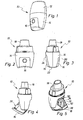
- the Indian FIG. 1 illustrated dry powder inhaler 10 includes a cover 12, a base housing 14 and a pivotally mounted on the base housing pivot member 16th
- FIGS. 2 and 3 is the inhaler 10 according to FIG. 1 shown without cover 12. Visible is a hollow mouthpiece 18 extending in the longitudinal direction of the inhaler 10, via which dry powder of an open capsule present in the inhaler can be inhaled.
- the pivot member 16 extends from the front side 20 of the base over the bottom 22 of the base toward the back 24 of the base. In side view, the pivot member 16 is thus formed U-shaped. In the in the FIGS. 1 to 3 illustrated normal position of the swivel part closes this largely flush with the outside of the base housing 14.
- the pivot member 16 is shown in a pivoted out of the base housing 14 pivot position.
- a capsule seat 26 arranged on the pivoting part 16 is accessible.
- a dry powder capsule can be inserted. After inserting the capsule, the pivoting part is swung back to its normal position.
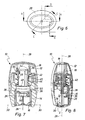
- the pivot member 16 is arranged at a value x offset from the central longitudinal axis 28 of the base housing or the mouthpiece arranged pivot axis 30 spaced.
- the pivot axis 30 also extends perpendicular to the central longitudinal axis 28.
- the pivot member 16 provides the pivotable arrangement V-shaped open pivot recesses 32 into which engage in the base 14 opposite each other and facing each other pivot pin 34.
- the capsule receptacle 26 the pivoting part 16 is fastened, has a substantially slightly larger than the male capsule formed recess 36, adjoin the funnel-like recess extending to surfaces 38.
- the recess 36 extends obliquely to the central longitudinal planes of the narrow side and broad side of the base housing and the mouthpiece, wherein the section AA in FIG. 6 along the central longitudinal plane of the broad side of the base housing 14 and the inhaler 10 extends. This is especially true FIG. 5 clear.
- the in FIG. 9 illustrated section CC according to FIG. 6 runs along the longitudinal direction of the recess.
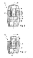
- FIGS. 9 and 10 It is clear that two opening means in the form of extending in the longitudinal direction of the mouthpiece needles 40 are arranged on the mouthpiece 18.
- the mouthpiece 18 together with the needles 40 along the longitudinal axis 28 down to the base housing depressible.
- FIG. 9 shows the normal position of the mouthpiece 18 and FIG. 10 In the depressed opening position, the needles 40 protrude into the capsule receptacle 26 and also into the recess 36 of the capsule receptacle 26.
- a capsule present in the capsule receptacle 36 is thereby perforated or opened when the mouthpiece 18 is pressed down.
- two spring elements 42, 44 are provided, which act on the mouthpiece 18 under bias in the normal position.
- a depression of the mouthpiece 18 thus takes place counter to the biasing force of the two spring elements 42, 44.
- two coaxially to each other about the central longitudinal axis 28 extending arranged spring elements 42, 44 are provided in the form of coil springs. Due to the provision of these two spring elements uniform loading of the mouthpiece 18 is achieved from the open position to the normal position. A jamming or jamming of the mouthpiece 18 during movement from the open position to the normal position is thereby counteracted. As such, the mouthpiece 18 is guided by a sleeve-like intermediate part 46 arranged on the base housing 14. The intermediate part 46 is hollow and closes the capsule receptacle 26 toward the mouthpiece 18 by means of a sieve-like structure 48.
- retaining lugs 54 are provided on the screen-like structure 48 of the intermediate part 46. These retaining lugs 54, in particular in FIG. 7 can be seen act with the mouthpiece 18 provided, radially inwardly projecting holding portions 56 together.
- the capsule receptacle In order to allow an influx of air during inhalation into the capsule receptacle 26 even in the pivoted-in state of the pivoting part 16, the capsule receptacle has, at its essentially circular upper edge 50, a suction inlet 52 which is in FIG. 5 good to see, up.
- the operation of the inhaler 10 shown in the figures is as follows: First, the pivot member 16 according to the FIGS. 4 and 5 swung out of the base housing 14. Subsequently, a dry capsule is inserted into the capsule receptacle 26 and the pivoting part is pivoted into the basic housing. Due to the in the folded state funnel-like obliquely downwardly extending surfaces 38, the capsule automatically enters the recess 36. Subsequently, to open the capsule, the mouthpiece 18 against the force of the springs 42, 44 to axially below pressed, like in FIG. 10 shown. The needles 40 open the capsule.
- the capsule is stripped on the sieve structure 48 and falls back into the capsule receptacle 36. Subsequently, the powder can be inhaled by attaching the mouth to the mouthpiece 18 and then aspirating air.
- the powder present in the capsule holder 26 is inhaled with the inhaled air through the sieve structure 48, the inside of the intermediate part 46 and the inside of the mouthpiece 18. Subsequently, the pivoting part 16 can be pivoted out of the base housing 14 and the empty capsule can be removed from the capsule receptacle 26 and disposed of.
- the capsule receptacle can be accommodated in the figures, not shown storage space. This allows a certain supply of capsules to be carried in the inhaler.
- the storage space is accessible, in particular, when the capsule receptacle is swung out for insertion or removal of capsules to be stored or stored, and is not accessible when the capsule receptacle is pivoted in.
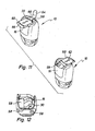
- FIGS. 11 and 12 show a variant of the inhaler 10, which in the FIG. 11 standing upside down, in which the pivoting part 16 is provided with two leading to a storage space openings 58 which are closed by a displaceably guided on the bottom 22 cap 60.
- the cap 60 can be displaced as shown by the double arrow 62 to two sides so that in each case one of the openings 58 is released, so that a capsule 64 can be removed.
- the cap 60 has stops or locking nubs, via which they are held in the closed position in which both openings 58 are closed and in the two open positions.
- the cap 60 may be provided with slightly protruding ridges 66, which facilitate a displacement of the cap, for example with the thumb.
- FIG. 12 shows the pivot member 16 in the position of use and withdrawn cap 60, from which two capsules 64 can be removed successively. Following the one opening 58, a magazine 68 for receiving a capsule 64 adjoins. It is also conceivable that in the swivel part 16, a magazine for receiving a plurality of chutes 64 is provided, which can then be output via a single opening 58 by means of a donor, not shown.
Description
Die Erfindung betrifft einen Trockenpulver-Inhalator mit einem Grundgehäuse, mit einer Kapselaufnahme für eine Kapsel mit Trockenpulver, mit wenigstens einem gegenüber dem Grundgehäuse beweglich angeordneten, nadel- oder klingenartigen Öffnungsmittel zum Öffnen der Kapsel, und mit einem Mundstück, durch welches das Trockenpulver einer geöffneten Kapsel inhalierbar ist.The invention relates to a dry powder inhaler with a basic housing, with a capsule receptacle for a capsule with dry powder, with at least one with respect to the base housing movably arranged, needle or blade-like opening means for opening the capsule, and with a mouthpiece through which the dry powder of an open Capsule is inhaled.
Ein derartiger Trockenpulver-Inhalator ist beispielsweise aus der
Bei derart bekannten Inhalatoren sind separate, mit den Öffnungsmitteln fest verbundene Betätigungsmittel vorgesehen, die zum Öffnen der Kapsel in das Grundgehäuse eingedrückt werden.In such known inhalers separate, firmly connected to the opening means actuating means are provided which are pressed to open the capsule into the base housing.
Aus der
Weitere, ähnliche Trockenpulver-Inhalator sind aus der
Aus der
Mit der vorliegenden Erfindung sollen Inhalatoren bereit gestellt werden, die einfach und bedienerfreundlich handzuhaben sind.The present invention is intended to provide inhalers which are easy to handle and user-friendly.
Zur Lösung der Aufgabe schlägt die Erfindung einen Trockenpulver-Inhalator mit den Merkmalen des Anspruchs 1 vor. Aufgrund der schwenkbaren Anordnung der Kapselaufnahme kann folglich ein einfaches und bedienerfreundliches Einführen der Kapsel in die Kapselaufnahme erfolgen. Dabei ist vorgesehen, dass die Schwenkachse, um die die Kapselaufnahme schwenkbar ist, senkrecht zur Mittellängsachse des Mundstücks oder des Grundgehäuses verläuft. Die Kapselaufnahme schwenkt dann folglich seitlich aus dem Grundgehäuse heraus. Zur schwenkbaren Anordnung der Kapselaufnahme sieht das Grundgehäuse auf seiner dem Mundstück abgewandten Seite das die Kapselaufnahme umfassende oder tragende Schwenkteil vor, das in seiner nicht ausgeschwenkten Normallage vorteilhafterweise wenigstens weitgehend bündig mit der Außenseite des Grundgehäuses abschließt. Dadurch wird erreicht, dass in der Normallage des Schwenkteils sich das Schwenkteil vorteilhafterweise in das Grundgehäuse einfügt.To solve the problem, the invention proposes a dry powder inhaler with the features of claim 1. As a result of the pivotable arrangement of the capsule holder, a simple and user-friendly insertion of the capsule into the capsule holder can consequently take place. It is provided that the pivot axis about which the capsule receptacle is pivotable, perpendicular to the central longitudinal axis of the mouthpiece or the base housing. The capsule holder then pivots laterally out of the base housing. For the pivotable arrangement of the capsule receptacle, the base housing on its side facing away from the mouthpiece, the swiveling part encompassing or supporting the capsule receptacle, which in its non-pivoted-out normal position advantageously terminates at least substantially flush with the outside of the base housing. This ensures that in the normal position of the pivoting part, the pivoting part advantageously fits into the base housing.
Vorteilhafterweise ist ferner vorgesehen, dass die Schwenkachse, um die die Kapselaufnahme schwenkbar ist, versetzt zur Mittellängsachse des Mundstücks oder des Grundgehäuses angeordnet ist. Aufgrund dieser nicht mittigen Anordnung der Schwenkachse wird erreicht, dass schon bei geringem Aufschwenkwinkel die Kapselaufnahme gut zugänglich ist.Advantageously, it is further provided that the pivot axis about which the capsule receptacle is pivotable, offset from the central longitudinal axis of the mouthpiece or the base housing is arranged. Because of this non-central arrangement of the pivot axis is achieved that even at low Aufschwenkwinkel the capsule holder is easily accessible.
Um das Mundstück aus seiner Öffnungslage wieder in seine Normallage zu bringen, kann vorgesehen sein, dass zwischen dem Gehäuse und dem Mundstück wenigstens ein Federelement vorgesehen ist. Beim Bewegen beziehungsweise Drücken des Mundstücks aus der Normallage in die Öffnungslage muss folglich eine Betätigungskraft bereitgestellt werden, die größer ist als die Federkraft, mit welcher das Mundstück in der Normallage gehalten wird. Bevorzugt kann ein Federelement oder können mehrere Federelemente vorgesehen sein. Das Vorsehen mehrerer Federelemente, beispielsweise mehrerer parallel zueinander oder koaxial ineinander angeordneter Schraubenfedern, kann den Vorteil haben, dass eine gleichmäßigere Vorspannkraft bereitgestellt wird, womit einem Verkanten oder Verklemmen des Mundstücks beim Überführen aus der Öffnungslage in die Normallage entgegen gewirkt wird.To bring the mouthpiece from its open position back to its normal position, it can be provided that at least one spring element is provided between the housing and the mouthpiece. When moving or pressing the mouthpiece from the normal position to the open position, consequently, an actuating force must be provided which is greater than the spring force with which the mouthpiece is held in the normal position. Preferably, a spring element or may be provided a plurality of spring elements. The provision of a plurality of spring elements, for example a plurality of mutually parallel or coaxially arranged helical springs, may have the advantage that a more uniform biasing force is provided, which counteracts jamming or jamming of the mouthpiece during transfer from the open position to the normal position.
Vorteilhafterweise wird das Mundstück aus der Normallage in die Öffnungslage in axialer Richtung bezüglich der Mittellängsachse des Mundstücks beziehungsweise des Grundgehäuses bewegt. Insbesondere kann das Mundstück derart angeordnet sein, dass es beim Überführen aus der Normallage in die Öffnungslage wenigstens abschnittsweise in das Grundgehäuse eingeführt wird.Advantageously, the mouthpiece is moved from the normal position into the open position in the axial direction with respect to the central longitudinal axis of the mouthpiece or of the base housing. In particular, the mouthpiece can be arranged such that it is at least partially introduced into the base housing during the transfer from the normal position into the open position.
Gemäß einer vorteilhaften Ausbildung der Erfindung kann vorgesehen sein, dass als Öffnungsmittel wenigstens eine sich in Längsrichtung des Mundstücks erstreckende Nadel Verwendung findet. Die Nadel kann dabei derart angeordnet sein, dass in der Normallage des Mundstücks die Nadel nicht in die Kapselaufnahme eingreift. Beim Niederdrücken des Mundstücks gelangt dann wenigstens die Nadelspitze in die Kapselaufnahme, in welche die entsprechende Kapsel eingelegt werden kann.According to an advantageous embodiment of the invention can be provided that at least one opening in the longitudinal direction of the mouth extending needle is used as the opening means. The needle can be arranged such that in the normal position of the mouthpiece, the needle does not engage in the capsule receptacle. When the mouthpiece is pressed down, at least the tip of the needle then passes into the capsule receptacle, into which the corresponding capsule can be inserted.
Zur Führung des Mundstücks aus seiner Normallage in die Öffnungslage kann am Grundgehäuse ein im Wesentlichen hülsenartiges Zwischenteil Verwendung finden. Hierdurch wird vorteilhafterweise über die gesamte Bewegungsbahn des Mundstücks das Mundstück geführt. Das hülsenartige Zwischenteil ist dabei vorteilhafterweise so ausgebildet, dass es beim Inhalieren des Trockenpulvers das Trockenpulver von der Kapselaufnahme zum Mundstück leitet. Dazu kann das Zwischenteil auf der der Kapselaufnahme zugewandten Seite eine siebartige Struktur aufweisen, die verhindert, dass das Kapselgehäuse beim Inhalieren in das Zwischenteil beziehungsweise in das Mundstück gelangen kann. Die siebartige Struktur hält folglich die Kapsel in der Kapselaufnahme zurück.To guide the mouthpiece from its normal position into the open position, a substantially sleeve-like intermediate part can be used on the base housing. As a result, the mouthpiece is advantageously guided over the entire movement path of the mouthpiece. The sleeve-like intermediate part is advantageously designed so that it directs the dry powder from the capsule holder to the mouthpiece when inhaling the dry powder. For this purpose, the intermediate part may have a sieve-like structure on the side facing the capsule receptacle, which prevents the capsule housing from reaching the intermediate part or the mouthpiece during inhalation. The sieve-like structure thus retains the capsule in the capsule receptacle.
Das Schwenkteil als solches kann dabei in Seitenansicht eine U-förmige Außenkontur aufweisen, die sich von der Vorderseite über die Unterseite bis zur Rückseite des Grundgehäuses erstrecken kann. Dies hat den Vorteil, dass ein Ausschwenken des Schwenkteils beispielsweise durch Greifen der Vorder- und der Rückseite des Schwenkteils mit zwei Fingern erfolgen kann. Insofern kann das Schwenkteil auf einfache Art und Weise aus der Normallage in die Schwenklage verschwenkt und anschließend, nach Einlegen der Kapsel, aus der Schwenklage in die Normallage zurückverschwenkt werden.The pivoting part as such may have in side view a U-shaped outer contour, which may extend from the front over the bottom to the back of the base housing. This has the advantage that swiveling out of the swiveling part can take place, for example, by gripping the front and the rear side of the swiveling part with two fingers. In this respect, the pivoting part can be pivoted in a simple manner from the normal position in the pivot position and then, after inserting the capsule, be swung back from the pivot position in the normal position.
Zwischen den beiden U-Schenkeln eines derartigen Schwenkteils ist dann vorteilhafterweise die Kapselaufnahme angeordnet. Die Kapselaufnahme kann dabei einteilig mit dem Schwenkteil ausgebildet sein oder auch als separates Bauteil am Schwenkteil befestigt sein.Between the two U-legs of such a pivoting part then advantageously the capsule receptacle is arranged. The capsule receptacle can be formed integrally with the pivoting part or can be attached to the pivoting part as a separate component.
Die Kapselaufnahme als solche weist vorteilhafterweise eine im Wesentlichen geringfügig größer als die Kapsel ausgebildete Vertiefung auf, an die sich trichterartig hin zur Vertiefung verlaufende Flächen anschließen. Hierdurch wird erreicht, dass beim Einlegen der Kapsel in die Kapselaufnahme diese automatisch die vorgesehene Lage in der Vertiefung einnimmt. Beim Öffnen der Kapsel befindet sich dann die Kapsel in der Vertiefung; ein seitliches Ausweichen der Kapsel beim Auftreffen der Öffnungsmittel auf die Kapsel kann dadurch nicht erfolgen.The capsule receptacle as such advantageously has a recess formed substantially slightly larger than the capsule, to which surfaces which extend in the shape of a funnel toward the depression follow. This ensures that when inserting the capsule in the capsule holder this automatically assumes the intended position in the depression. When opening the capsule is then the capsule in the recess; a lateral deflection of the capsule upon impact of the opening means on the capsule can not be done.
Vorzugsweise verläuft die Längsachse der Vertiefung der Kapselaufnahme schräg zu einer Mittellängsebene des Grundgehäuses. Die Längsachse der Vertiefung kann dabei beispielsweise mit der Mittellängsebene der Breitseite des Grundgehäuses einen Winkel von cirka 45° einschließen. Ein derartiger Winkel hat den Vorteil, dass die Kapsel in der aufgeschwenkten Kapselaufnahme selbst in die Vertiefung findet. Ferner kann die Kapsel nach Gebrauch des Inhalators auf einfache Art und Weise aus der Vertiefung herausgenommen werden.Preferably, the longitudinal axis of the recess of the capsule receptacle extends obliquely to a central longitudinal plane of the base housing. The longitudinal axis of the recess may include an angle of approximately 45 °, for example, with the central longitudinal plane of the broad side of the base housing. Such an angle has the advantage that the capsule finds itself in the swung-capsule receptacle in the depression. Further, the capsule may after use of the inhaler be taken out of the well in a simple way.
Die Kapselaufnahme kann zudem durch eine im Wesentlichen kreisrunde Oberkante begrenzt werden. Dadurch kann ein definierter Abschluss beziehungsweise Anschluss an die der Kapselaufnahme zugewandte Unterseite des hülsenartigen Zwischenteils bereitgestellt werden. Im Bereich der Oberkante der Kapselaufnahme kann zudem ein Ansaugeinlass für Ansaugluft beim Inhalieren vorgesehen sein. Der Ansaugeinlass ist dabei vorteilhafterweise senkrecht zur Mittellängsachse des Gehäuses beziehungsweise des Mundstücks angeordnet.The capsule receptacle can also be limited by a substantially circular upper edge. As a result, a defined termination or connection to the capsule receptacle facing underside of the sleeve-like intermediate part can be provided. In the region of the upper edge of the capsule receptacle, a suction intake for intake air during inhalation may also be provided. The suction inlet is advantageously arranged perpendicular to the central longitudinal axis of the housing or the mouthpiece.
Es ist zudem vorteilhaft, wenn die Kapselaufnahme einen Lagerraum zur Lagerung von Kapseln aufweist. Dadurch kann ein gewisser Vorrat von Kapseln im Inhalator mitgeführt werden. Dabei ist denkbar, dass der Lagerraum bei herausgeschwenkter Kapselaufnahme zum Einlegen bzw. Herausnehmen von zu lagernden bzw. gelagerten Kapseln zugänglich ist und bei eingeschwenkter Kapselaufnahme nicht zugänglich ist. Beim Transport des Inhalators mit geschlossener Kapselaufnahme sind die Kapseln im Lagerraum verliersicher untergebracht.It is also advantageous if the capsule receptacle has a storage space for storing capsules. This allows a certain supply of capsules to be carried in the inhaler. It is conceivable that the storage room with swung-out capsule receptacle is accessible for inserting or removing stored or stored capsules and is not accessible when swiveled capsule holder. When transporting the inhaler with closed capsule holder, the capsules are stored in the storage room captive.
Weitere Einzelheiten und vorteilhafte Ausgestaltungen der Erfindung sind den Unteransprüchen und der folgenden Beschreibung zu entnehmen, in der zwei in der Zeichnung dargestellte Ausführungsbeispiele näher beschrieben und erläutert sind.Further details and advantageous embodiments of the invention are described in the dependent claims and the following description in which two embodiments shown in the drawings are described and explained in detail.
Es zeigen:
- Figur 1
- eine perspektivische Ansicht eines erfindungsgemäßen Trockenpulver-Inhalators mit aufgesetztem Deckel;
- Figur 2
- die Vorderansicht des Inhalators gemäß
Figur 1 ohne Deckel; - Figur 3
- die Seitenansicht des Inhalators gemäß
Figur 1 ; - Figur 4
- die Ansicht des Inhalators gemäß
Figur 3 mit aufgeschwenkter Kapselaufnahme; - Figur 5
- eine perspektivische Ansicht von
Figur 4 ; - Figur 6
- eine Draufsicht auf den Inhalator gemäß
Figur 1 ; - Figur 7
- einen Schnitt entlang der Linie A-A gemäß
Figur 6 ; - Figur 8
- einen Schnitt entlang der Linie D-D gemäß
Figur 6 ; - Figur 9
- einen Schnitt entlang der Linie C-C gemäß
Figur 6 ; Figur 10- den Schnitt gemäß
Figur 9 mit niedergedrücktem Mundstück; - Figur 11
- eine Draufsicht auf die Unterseite des umgedrehten Inhalators; und
Figur 12- das Schwenkteil mit abgezogener Kappe.
- FIG. 1
- a perspective view of a dry powder inhaler according to the invention with attached lid;
- FIG. 2
- the front view of the inhaler according to
FIG. 1 lidless; - FIG. 3
- the side view of the inhaler according to
FIG. 1 ; - FIG. 4
- the view of the inhaler according to
FIG. 3 with swiveled capsule holder; - FIG. 5
- a perspective view of
FIG. 4 ; - FIG. 6
- a plan view of the inhaler according to
FIG. 1 ; - FIG. 7
- a section along the line AA according to
FIG. 6 ; - FIG. 8
- a section along the line DD according to
FIG. 6 ; - FIG. 9
- a section along the line CC according to
FIG. 6 ; - FIG. 10
- the cut according to
FIG. 9 with mouthpiece depressed - FIG. 11
- a plan view of the underside of the inverted inhaler; and
- FIG. 12
- the pivoting part with deducted cap.
Der in der
In den
Wie aus insbesondere
In den
Wie insbesondere aus den
Insbesondere aus den Schnitten der
Especially from the sections of the
Aus
Um das Mundteil 18 in der Normallage entgegen der Federkraft der Federelemente 42, 44 zu sichern, sind an der siebartigen Struktur 48 des Zwischenteils 46 nach radial außen ragende Haltenasen 54 vorgesehen. Diese Haltenasen 54, die insbesondere in
Um auch im eingeschwenkten Zustand des Schwenkteils 16 ein Einströmen von Luft beim Inhalieren in die Kapselaufnahme 26 zu ermöglichen, weist die Kapselaufnahme an ihrer im Wesentlichen kreisrunden Oberkante 50 einen Ansaugeinlass 52, der in
Der Gebrauchsablauf des in den Figuren dargestellten Inhalators 10 ist folgendermaßen: Zunächst wird das Schwenkteil 16 gemäß den
Zur Lagerung von noch zu benützenden Kapseln kann die Kapselaufnahme in den Figuren nicht dargestellten Lagerraum beherbergen. Dadurch kann ein gewisser Vorrat von Kapseln im Inhalator mitgeführt werden. Der Lagerraum ist dabei insbesondere bei herausgeschwenkter Kapselaufnahme zum Einlegen bzw. Herausnehmen von zu lagernden bzw. gelagerten Kapseln zugänglich und bei eingeschwenkter Kapselaufnahme nicht zugänglich.For storage of capsules still to be used, the capsule receptacle can be accommodated in the figures, not shown storage space. This allows a certain supply of capsules to be carried in the inhaler. The storage space is accessible, in particular, when the capsule receptacle is swung out for insertion or removal of capsules to be stored or stored, and is not accessible when the capsule receptacle is pivoted in.
Die
Die
Claims (13)
- A dry-powder inhaler (10) having a basic housing (14), having a capsule receptacle (26) for a capsule with dry powder, having at least one needle- or blade-like opening means (40), disposed movably relative to the basic housing (14), for opening the capsule, and having a mouthpiece (18) through which the dry powder can be inhaled from an opened capsule, the opening means (40) being secured to the mouthpiece (18), and the mouthpiece (18) being movable relative to the basic housing (14) from a normal position into an opening position that opens the capsule, characterized in that the basic housing (14), on its side remote from the mouthpiece (18), provides a pivoting part (16), including or bearing the capsule receptacle (26), which pivoting part is disposed pivotably about a pivot axis (30), extending perpendicular to the central longitudinal axis (28) of the mouthpiece (18) or of the basic housing (14), in such a way that in its unpivoted normal position it is at least extensively flush with the outside of the basic housing (14) and can be pivoted outward in at least some portions for the insertion of a capsule.
- The dry-powder inhaler (10) of claim 1, characterized in that between the basic housing (14) and the mouthpiece (18), a spring element (42) is provided, which keeps the mouthpiece (18) prestressed in the normal position.
- The dry-powder inhaler (10) of claim 1, characterized in that an essentially tubular intermediate part (46) for guiding the mouthpiece (18) is disposed on the basic housing (14), and the intermediate part (46) carries the dry powder from the capsule receptacle (26) to the mouthpiece upon inhalation and has a sievelike structure (48) on its side toward the capsule receptacle (26).
- The dry-powder inhaler (10) of claim 3, characterized in that between the basic housing (14) and the mouthpiece (18), a spring element (42) is provided, which keeps the mouthpiece (18) prestressed in the normal position, and because of the spring element (42), the mouthpiece is returned automatically from the opening position to the normal position and the capsule is stripped off at the sieve structure (46), so that the capsule drops back into the capsule receptacle (26).
- The dry-powder inhaler (10) of one of the foregoing claims, characterized in that the opening means (40) is embodied as at least one needle extending in the longitudinal direction of the mouthpiece (18).
- The dry-powder inhaler (10) of one of the foregoing claims, characterized in that the pivot axis (30) is offset from the central longitudinal axis (28) of the mouthpiece (18) or of the basic housing (14).
- The dry-powder inhaler (10) of one of the foregoing claims, characterized in that the pivoting part (16), in side view, has a U-shaped outer contour which extends from the front side (20), across the underside (22,) to the back side (24) of the basic housing (14).
- The dry-powder inhaler (10) of claim 7, characterized in that the capsule receptacle (26) is disposed between the two legs of the U of the pivoting part (16).
- The dry-powder inhaler (10) of one of the foregoing claims, characterized in that the capsule receptacle (26) has an indentation (36), which is essentially embodied as slightly larger than the capsule and is adjoined by faces (38) extending toward the indentation in funnel-like fashion.
- The dry-powder inhaler (10) of claim 9, characterized in that the longitudinal axis of the indentation extends obliquely to a central longitudinal plane of the basic housing.
- The dry-powder inhaler (10) of one of the foregoing claims, characterized in that the capsule receptacle (26) is bounded by an essentially circular upper edge (50).
- The dry-powder inhaler (10) of claim 11, characterized in that in the vicinity of the upper edge (50), at least one aspiration inlet (52) for aspirating air is provided.
- The dry-powder inhaler (10) of at least one of the foregoing claims, characterized in that a storage chamber for keeping capsules (64) on hand is provided in the pivoting part (16).
Priority Applications (2)
| Application Number | Priority Date | Filing Date | Title |
|---|---|---|---|
| PL07711576T PL2010258T3 (en) | 2006-02-24 | 2007-02-19 | Dry powder inhaler |
| SI200731297T SI2010258T1 (en) | 2006-02-24 | 2007-02-19 | Dry powder inhaler |
Applications Claiming Priority (2)
| Application Number | Priority Date | Filing Date | Title |
|---|---|---|---|
| DE102006010089A DE102006010089A1 (en) | 2006-02-24 | 2006-02-24 | The dry powder inhaler |
| PCT/EP2007/001408 WO2007098870A1 (en) | 2006-02-24 | 2007-02-19 | Dry powder inhaler |
Publications (2)
| Publication Number | Publication Date |
|---|---|
| EP2010258A1 EP2010258A1 (en) | 2009-01-07 |
| EP2010258B1 true EP2010258B1 (en) | 2013-07-31 |
Family
ID=37909683
Family Applications (1)
| Application Number | Title | Priority Date | Filing Date |
|---|---|---|---|
| EP07711576.4A Active EP2010258B1 (en) | 2006-02-24 | 2007-02-19 | Dry powder inhaler |
Country Status (15)
| Country | Link |
|---|---|
| US (1) | US8539946B2 (en) |
| EP (1) | EP2010258B1 (en) |
| JP (1) | JP5177891B2 (en) |
| KR (1) | KR101150000B1 (en) |
| CN (1) | CN101389367B (en) |
| AU (1) | AU2007219498B2 (en) |
| BR (1) | BRPI0710078A2 (en) |
| CA (1) | CA2644482C (en) |
| DE (1) | DE102006010089A1 (en) |
| ES (1) | ES2429188T3 (en) |
| MX (1) | MX2008010681A (en) |
| PL (1) | PL2010258T3 (en) |
| RU (1) | RU2424000C2 (en) |
| SI (1) | SI2010258T1 (en) |
| WO (1) | WO2007098870A1 (en) |
Families Citing this family (50)
| Publication number | Priority date | Publication date | Assignee | Title |
|---|---|---|---|---|
| US9006175B2 (en) | 1999-06-29 | 2015-04-14 | Mannkind Corporation | Potentiation of glucose elimination |
| EP1894591B1 (en) | 2002-03-20 | 2013-06-26 | MannKind Corporation | Cartridge for an inhalation apparatus |
| CN101010305B (en) | 2004-08-20 | 2010-08-11 | 曼金德公司 | Catalysis of diketopiperazine synthesis |
| PL2322180T3 (en) | 2004-08-23 | 2015-10-30 | Mannkind Corp | Diketopiperazine salts for drug delivery |
| GB0507711D0 (en) | 2005-04-15 | 2005-05-25 | Vectura Group Plc | Improved blister piercing |
| CN104324362B (en) | 2005-09-14 | 2018-04-24 | 曼金德公司 | Method for preparation of drug based on improving affinity of the active agent to crystalline microparticle surfaces |
| CN104383546B (en) | 2006-02-22 | 2021-03-02 | 曼金德公司 | Method for improving the pharmaceutical properties of microparticles comprising diketopiperazines and an active agent |
| EP2020249A1 (en) | 2007-08-01 | 2009-02-04 | Boehringer Ingelheim Pharma GmbH & Co. KG | Inhalator |
| DE102007040366A1 (en) * | 2007-08-17 | 2009-02-19 | Aha Kunststofftechnik Gmbh | The dry powder inhaler |
| WO2011163272A1 (en) | 2010-06-21 | 2011-12-29 | Mannkind Corporation | Dry powder drug delivery system and methods |
| HUE027246T2 (en) * | 2008-01-24 | 2016-10-28 | Vectura Delivery Devices Ltd | Inhaler |
| US8485180B2 (en) | 2008-06-13 | 2013-07-16 | Mannkind Corporation | Dry powder drug delivery system |
| DK2293833T3 (en) | 2008-06-13 | 2016-05-23 | Mannkind Corp | DRY POWDER INHALER AND MEDICINAL ADMINISTRATION SYSTEM |
| KR101628410B1 (en) | 2008-06-20 | 2016-06-08 | 맨카인드 코포레이션 | An interactive apparatus and method for real-time profiling of inhalation efforts |
| TWI494123B (en) | 2008-08-11 | 2015-08-01 | Mannkind Corp | Use of ultrarapid acting insulin |
| US8314106B2 (en) | 2008-12-29 | 2012-11-20 | Mannkind Corporation | Substituted diketopiperazine analogs for use as drug delivery agents |
| GB0901520D0 (en) | 2009-01-30 | 2009-03-11 | Vectura Delivery Devices Ltd | Inhaler |
| DK2405963T3 (en) | 2009-03-11 | 2013-12-16 | Mannkind Corp | DEVICE, SYSTEM AND PROCEDURE FOR MEASURING RESISTANCE IN AN INHALATOR |
| BRPI1013154B1 (en) | 2009-06-12 | 2020-04-07 | Mannkind Corp | MICROPARTICLES OF DICETOPIPERAZINE WITH SPECIFIC SURFACE AREAS DEFINED, DRY POWDER UNDERSTANDING THE REFERRED MICROPARTICLES, METHOD FOR FORMATION OF THE REFERENCESMICROPARTICLES AND THE FORMATION OF MICROPARTYSTEMS |
| DE102009037840B4 (en) | 2009-08-18 | 2012-08-16 | Gamptec Gmbh | Inhalation device and method for inhaling an active ingredient from a capsule |
| EP2496295A1 (en) | 2009-11-03 | 2012-09-12 | MannKind Corporation | An apparatus and method for simulating inhalation efforts |
| PT105065B (en) | 2010-04-26 | 2012-07-31 | Hovione Farmaciencia S A | A SIMPLE INHALER OF CAPSULES |
| SG194034A1 (en) | 2011-04-01 | 2013-11-29 | Mannkind Corp | Blister package for pharmaceutical cartridges |
| WO2012174472A1 (en) | 2011-06-17 | 2012-12-20 | Mannkind Corporation | High capacity diketopiperazine microparticles |
| WO2013016784A1 (en) | 2011-08-04 | 2013-02-07 | Victor Esteve | Dry powder inhaler |
| AU2012328885B2 (en) | 2011-10-24 | 2017-08-31 | Mannkind Corporation | Methods and compositions for treating pain |
| DE102012103482A1 (en) * | 2012-04-20 | 2013-10-24 | Alfred Von Schuckmann | Device for inhaling powdery substances |
| CN108057154B (en) | 2012-07-12 | 2021-04-16 | 曼金德公司 | Dry powder drug delivery system and method |
| WO2014066856A1 (en) | 2012-10-26 | 2014-05-01 | Mannkind Corporation | Inhalable influenza vaccine compositions and methods |
| GB201301192D0 (en) | 2013-01-23 | 2013-03-06 | Vectura Delivery Devices Ltd | A blister piercing element for a dry powder inhaler |
| ES2928365T3 (en) | 2013-03-15 | 2022-11-17 | Mannkind Corp | Microcrystalline diketopiperazine compositions, methods of preparation and use thereof |
| US20160158470A1 (en) * | 2013-07-16 | 2016-06-09 | Victor Esteve | Powder inhaler |
| EP3021834A1 (en) | 2013-07-18 | 2016-05-25 | MannKind Corporation | Heat-stable dry powder pharmaceutical compositions and methods |
| CN105517607A (en) | 2013-08-05 | 2016-04-20 | 曼金德公司 | Insufflation apparatus and methods |
| NO2709641T3 (en) * | 2014-03-10 | 2018-05-12 | ||
| US10307464B2 (en) | 2014-03-28 | 2019-06-04 | Mannkind Corporation | Use of ultrarapid acting insulin |
| US10561806B2 (en) | 2014-10-02 | 2020-02-18 | Mannkind Corporation | Mouthpiece cover for an inhaler |
| CN104984449B (en) * | 2015-07-30 | 2018-06-01 | 中山市美捷时包装制品有限公司 | A kind of capsule powder inhaler of turnable opening |
| USD867575S1 (en) * | 2015-11-19 | 2019-11-19 | Emphasys Importadora Exportadora e Distribuidora | Inhaler |
| CA169756S (en) | 2016-02-08 | 2017-09-01 | Nicoventures Holdings Ltd | Electronic cigarette |
| GB201605105D0 (en) | 2016-03-24 | 2016-05-11 | Nicoventures Holdings Ltd | Vapour provision apparatus |
| GB201605102D0 (en) | 2016-03-24 | 2016-05-11 | Nicoventures Holdings Ltd | Mechanical connector for electronic vapour provision system |
| GB201605100D0 (en) | 2016-03-24 | 2016-05-11 | Nicoventures Holdings Ltd | Vapour provision system |
| GB201605101D0 (en) | 2016-03-24 | 2016-05-11 | Nicoventures Holdings Ltd | Electronic vapour provision system |
| WO2018015712A1 (en) | 2016-07-22 | 2018-01-25 | Nicoventures Holdings Limited | Case for a vapour provision device |
| RU2730961C1 (en) * | 2016-12-20 | 2020-08-26 | Эмфэсиз Импортадора Эшпортадора Э Дистрибуидора Лтда. | Dry powder inhaler |
| MA48453A (en) | 2017-04-28 | 2020-03-04 | Softhale Nv | INHALATION DEVICE AND PROCESS |
| CN109821117A (en) * | 2017-11-23 | 2019-05-31 | 正大天晴药业集团股份有限公司 | Powder release device and method |
| BR112020011285A2 (en) * | 2017-12-13 | 2020-11-24 | Emphasys Importadora Exportadora E Distribuidora Ltda. | dry powder inhaler |
| USD983354S1 (en) | 2020-12-21 | 2023-04-11 | Rpc Formatec Gmbh | Inhaler |
Family Cites Families (21)
| Publication number | Priority date | Publication date | Assignee | Title |
|---|---|---|---|---|
| FR2224175B1 (en) * | 1973-04-04 | 1978-04-14 | Isf Spa | |
| GB1506131A (en) | 1976-02-04 | 1978-04-05 | Shell Bv | Preparation of dihydromyrcenol or a carboxylic ester thereof |
| GB1562732A (en) * | 1976-02-10 | 1980-03-12 | Allen & Hanburys Ltd | Device for dispensing medicaments |
| IT1230313B (en) * | 1989-07-07 | 1991-10-18 | Somova Spa | INHALER FOR CAPSULES MEDICATIONS. |
| NL9002706A (en) * | 1990-12-10 | 1992-07-01 | Pharmachemie Bv | Apparatus for use when inhaling powdered materials packaged in rod capsules. |
| IL108780A (en) * | 1993-02-27 | 1999-06-20 | Fisons Plc | Inhalation device |
| US5372128A (en) * | 1993-04-14 | 1994-12-13 | Habley Medical Technology Corporation | Fluidizing powder inhaler |
| PT101450B (en) | 1994-02-02 | 1999-11-30 | Hovione Produtos Farmaceuticos | NEW INHALATION DEVICE |
| JP3372105B2 (en) * | 1994-05-26 | 2003-01-27 | 株式会社日立ユニシアオートモティブ | Inhalation type dispenser |
| DE19637125A1 (en) | 1996-09-12 | 1998-03-19 | Schuckmann Alfred Von | Inhaler device |
| DE69829139T2 (en) * | 1997-01-30 | 2006-04-06 | Hitachi, Ltd. | MEDICATOR OF INTAKE TYPE |
| DE19704849B4 (en) | 1997-02-08 | 2011-02-17 | Ing. Erich Pfeiffer Gmbh | Discharge device for media |
| PT101988B (en) * | 1997-04-04 | 2004-02-27 | Hovione Farmaciencia Sa | SYSTEM OF ORIENTATION AND POSITIONING OF AN OBJECT |
| DE19817417A1 (en) * | 1998-04-18 | 1999-10-21 | Pfeiffer Erich Gmbh & Co Kg | Dispenser for media, especially powder |
| DE19942791A1 (en) * | 1999-09-08 | 2001-03-15 | Pfeiffer Erich Gmbh & Co Kg | Media Donor |
| US6766799B2 (en) * | 2001-04-16 | 2004-07-27 | Advanced Inhalation Research, Inc. | Inhalation device |
| EG24184A (en) * | 2001-06-15 | 2008-10-08 | Otsuka Pharma Co Ltd | Dry powder inhalation system for transpulmonary |
| ITMI20010357U1 (en) | 2001-06-28 | 2002-12-30 | Plastiape Spa | INHALER DEVICE |
| ITMI20020078A1 (en) * | 2002-01-16 | 2003-07-16 | Fabrizio Niccolai | DEVICE USABLE IN THE TREATMENT OF RESPIRATORY TRACT AFFECTIONS |
| DE102004019566A1 (en) * | 2004-04-22 | 2005-11-10 | E. Braun Gmbh | Inhaler for powder medicaments holds a powder capsule which is opened at its ends and is centrally positioned within the air channel of the inhaler |
| US7861712B2 (en) * | 2004-04-23 | 2011-01-04 | Manta Product Development | Sealed capsule including an integrated puncturing mechanism |
-
2006
- 2006-02-24 DE DE102006010089A patent/DE102006010089A1/en not_active Ceased
-
2007
- 2007-02-19 MX MX2008010681A patent/MX2008010681A/en active IP Right Grant
- 2007-02-19 PL PL07711576T patent/PL2010258T3/en unknown
- 2007-02-19 ES ES07711576T patent/ES2429188T3/en active Active
- 2007-02-19 EP EP07711576.4A patent/EP2010258B1/en active Active
- 2007-02-19 BR BRPI0710078-7A patent/BRPI0710078A2/en not_active Application Discontinuation
- 2007-02-19 WO PCT/EP2007/001408 patent/WO2007098870A1/en active Application Filing
- 2007-02-19 AU AU2007219498A patent/AU2007219498B2/en not_active Ceased
- 2007-02-19 KR KR1020087023180A patent/KR101150000B1/en active IP Right Grant
- 2007-02-19 CN CN2007800066115A patent/CN101389367B/en not_active Expired - Fee Related
- 2007-02-19 US US12/224,167 patent/US8539946B2/en active Active
- 2007-02-19 JP JP2008555680A patent/JP5177891B2/en not_active Expired - Fee Related
- 2007-02-19 RU RU2008136545/14A patent/RU2424000C2/en active IP Right Revival
- 2007-02-19 SI SI200731297T patent/SI2010258T1/en unknown
- 2007-02-19 CA CA2644482A patent/CA2644482C/en active Active
Also Published As
| Publication number | Publication date |
|---|---|
| CA2644482A1 (en) | 2007-09-07 |
| MX2008010681A (en) | 2008-11-14 |
| AU2007219498A2 (en) | 2008-10-02 |
| WO2007098870A1 (en) | 2007-09-07 |
| CN101389367A (en) | 2009-03-18 |
| RU2424000C2 (en) | 2011-07-20 |
| PL2010258T3 (en) | 2013-11-29 |
| DE102006010089A1 (en) | 2007-10-18 |
| AU2007219498B2 (en) | 2013-08-22 |
| AU2007219498A1 (en) | 2007-09-07 |
| JP2009527300A (en) | 2009-07-30 |
| ES2429188T3 (en) | 2013-11-13 |
| SI2010258T1 (en) | 2013-10-30 |
| EP2010258A1 (en) | 2009-01-07 |
| KR20090056928A (en) | 2009-06-03 |
| CN101389367B (en) | 2011-10-05 |
| WO2007098870A8 (en) | 2008-11-06 |
| US8539946B2 (en) | 2013-09-24 |
| KR101150000B1 (en) | 2012-06-01 |
| BRPI0710078A2 (en) | 2011-08-02 |
| RU2008136545A (en) | 2010-03-27 |
| CA2644482C (en) | 2014-11-18 |
| US20110120463A1 (en) | 2011-05-26 |
| JP5177891B2 (en) | 2013-04-10 |
Similar Documents
| Publication | Publication Date | Title |
|---|---|---|
| EP2010258B1 (en) | Dry powder inhaler | |
| DE60212764T2 (en) | inhaler | |
| DE1917911C3 (en) | ||
| WO2005044353A1 (en) | Powder inhaler | |
| EP0545960B1 (en) | Inhalation device without propellant gas | |
| DE2449179C3 (en) | Powdered substance inhaler | |
| DE2642174A1 (en) | DEVICE FOR DISPENSING AN AEROSOL | |
| AT400810B (en) | INHALATION DEVICE | |
| DE3625685C2 (en) | ||
| CH625127A5 (en) | ||
| DE7924612U1 (en) | INHALATION DEVICE FOR DELIVERING A POWDERED MEDICINE | |
| DE1917911B2 (en) | INHALATION DEVICE | |
| CH646064A5 (en) | INHALATOR FOR ORAL OR NASAL POWDERED MEDICINE. | |
| WO2007009872A1 (en) | Inhaler for powdery, especially medical substances | |
| EP2707067A1 (en) | Device for inhaling pulverulent substances | |
| DE102006029753A1 (en) | Inhaler for powdered substances | |
| DE7924611U1 (en) | INHALATION DEVICE FOR DELIVERING A POWDERED MEDICINE FROM A CONTAINER | |
| CH670048A5 (en) | ||
| DE602004011902T2 (en) | DONOR | |
| DE3816276A1 (en) | INHALATION DEVICE | |
| WO2009024254A2 (en) | Dry powder inhaler | |
| DE10258360A1 (en) | Chamber for accommodation of disposable capsules for powder inhalers has an inner surface with protruding elements serving as distance pieces between the capsules | |
| EP3419707B1 (en) | Inhaler | |
| WO2006027313A1 (en) | Inhaler device | |
| DE3743896A1 (en) | ERGONOMIC SPRAY CAN |
Legal Events
| Date | Code | Title | Description |
|---|---|---|---|
| PUAI | Public reference made under article 153(3) epc to a published international application that has entered the european phase |
Free format text: ORIGINAL CODE: 0009012 |
|
| 17P | Request for examination filed |
Effective date: 20080801 |
|
| AK | Designated contracting states |
Kind code of ref document: A1 Designated state(s): AT BE BG CH CY CZ DE DK EE ES FI FR GB GR HU IE IS IT LI LT LU LV MC NL PL PT RO SE SI SK TR |
|
| AX | Request for extension of the european patent |
Extension state: AL BA HR MK RS |
|
| 17Q | First examination report despatched |
Effective date: 20110224 |
|
| DAX | Request for extension of the european patent (deleted) | ||
| GRAP | Despatch of communication of intention to grant a patent |
Free format text: ORIGINAL CODE: EPIDOSNIGR1 |
|
| GRAS | Grant fee paid |
Free format text: ORIGINAL CODE: EPIDOSNIGR3 |
|
| GRAA | (expected) grant |
Free format text: ORIGINAL CODE: 0009210 |
|
| AK | Designated contracting states |
Kind code of ref document: B1 Designated state(s): AT BE BG CH CY CZ DE DK EE ES FI FR GB GR HU IE IS IT LI LT LU LV MC NL PL PT RO SE SI SK TR |
|
| RAP1 | Party data changed (applicant data changed or rights of an application transferred) |
Owner name: EMPHASYS IMPORTADORA EXPORTADORA E DISTRIBUIDORA L |
|
| REG | Reference to a national code |
Ref country code: GB Ref legal event code: FG4D Free format text: NOT ENGLISH Ref country code: CH Ref legal event code: EP |
|
| REG | Reference to a national code |
Ref country code: AT Ref legal event code: REF Ref document number: 624250 Country of ref document: AT Kind code of ref document: T Effective date: 20130815 |
|
| REG | Reference to a national code |
Ref country code: IE Ref legal event code: FG4D Free format text: LANGUAGE OF EP DOCUMENT: GERMAN |
|
| REG | Reference to a national code |
Ref country code: DE Ref legal event code: R096 Ref document number: 502007012097 Country of ref document: DE Effective date: 20130926 |
|
| REG | Reference to a national code |
Ref country code: CH Ref legal event code: NV Representative=s name: DREISS PATENTANWAELTE, DE |
|
| REG | Reference to a national code |
Ref country code: RO Ref legal event code: EPE |
|
| REG | Reference to a national code |
Ref country code: ES Ref legal event code: FG2A Ref document number: 2429188 Country of ref document: ES Kind code of ref document: T3 Effective date: 20131113 |
|
| REG | Reference to a national code |
Ref country code: NL Ref legal event code: T3 |
|
| REG | Reference to a national code |
Ref country code: PL Ref legal event code: T3 |
|
| REG | Reference to a national code |
Ref country code: LT Ref legal event code: MG4D |
|
| PG25 | Lapsed in a contracting state [announced via postgrant information from national office to epo] |
Ref country code: CY Free format text: LAPSE BECAUSE OF FAILURE TO SUBMIT A TRANSLATION OF THE DESCRIPTION OR TO PAY THE FEE WITHIN THE PRESCRIBED TIME-LIMIT Effective date: 20130619 Ref country code: PT Free format text: LAPSE BECAUSE OF FAILURE TO SUBMIT A TRANSLATION OF THE DESCRIPTION OR TO PAY THE FEE WITHIN THE PRESCRIBED TIME-LIMIT Effective date: 20131202 Ref country code: SE Free format text: LAPSE BECAUSE OF FAILURE TO SUBMIT A TRANSLATION OF THE DESCRIPTION OR TO PAY THE FEE WITHIN THE PRESCRIBED TIME-LIMIT Effective date: 20130731 Ref country code: IS Free format text: LAPSE BECAUSE OF FAILURE TO SUBMIT A TRANSLATION OF THE DESCRIPTION OR TO PAY THE FEE WITHIN THE PRESCRIBED TIME-LIMIT Effective date: 20131130 Ref country code: LT Free format text: LAPSE BECAUSE OF FAILURE TO SUBMIT A TRANSLATION OF THE DESCRIPTION OR TO PAY THE FEE WITHIN THE PRESCRIBED TIME-LIMIT Effective date: 20130731 |
|
| PG25 | Lapsed in a contracting state [announced via postgrant information from national office to epo] |
Ref country code: LV Free format text: LAPSE BECAUSE OF FAILURE TO SUBMIT A TRANSLATION OF THE DESCRIPTION OR TO PAY THE FEE WITHIN THE PRESCRIBED TIME-LIMIT Effective date: 20130731 Ref country code: GR Free format text: LAPSE BECAUSE OF FAILURE TO SUBMIT A TRANSLATION OF THE DESCRIPTION OR TO PAY THE FEE WITHIN THE PRESCRIBED TIME-LIMIT Effective date: 20131101 Ref country code: FI Free format text: LAPSE BECAUSE OF FAILURE TO SUBMIT A TRANSLATION OF THE DESCRIPTION OR TO PAY THE FEE WITHIN THE PRESCRIBED TIME-LIMIT Effective date: 20130731 |
|
| PG25 | Lapsed in a contracting state [announced via postgrant information from national office to epo] |
Ref country code: CY Free format text: LAPSE BECAUSE OF FAILURE TO SUBMIT A TRANSLATION OF THE DESCRIPTION OR TO PAY THE FEE WITHIN THE PRESCRIBED TIME-LIMIT Effective date: 20130731 |
|
| REG | Reference to a national code |
Ref country code: CH Ref legal event code: PFA Owner name: EMPHASYS IMPORTADORA EXPORTADORA E DISTRIBUIDO, BR Free format text: FORMER OWNER: EMPHASYS IMPORTADORA EXPORTADORA E DISTRIBUIDORA LTDA., BR |
|
| PG25 | Lapsed in a contracting state [announced via postgrant information from national office to epo] |
Ref country code: EE Free format text: LAPSE BECAUSE OF FAILURE TO SUBMIT A TRANSLATION OF THE DESCRIPTION OR TO PAY THE FEE WITHIN THE PRESCRIBED TIME-LIMIT Effective date: 20130731 Ref country code: DK Free format text: LAPSE BECAUSE OF FAILURE TO SUBMIT A TRANSLATION OF THE DESCRIPTION OR TO PAY THE FEE WITHIN THE PRESCRIBED TIME-LIMIT Effective date: 20130731 Ref country code: SK Free format text: LAPSE BECAUSE OF FAILURE TO SUBMIT A TRANSLATION OF THE DESCRIPTION OR TO PAY THE FEE WITHIN THE PRESCRIBED TIME-LIMIT Effective date: 20130731 |
|
| PLBE | No opposition filed within time limit |
Free format text: ORIGINAL CODE: 0009261 |
|
| STAA | Information on the status of an ep patent application or granted ep patent |
Free format text: STATUS: NO OPPOSITION FILED WITHIN TIME LIMIT |
|
| 26N | No opposition filed |
Effective date: 20140502 |
|
| REG | Reference to a national code |
Ref country code: HU Ref legal event code: AG4A Ref document number: E019713 Country of ref document: HU |
|
| REG | Reference to a national code |
Ref country code: DE Ref legal event code: R097 Ref document number: 502007012097 Country of ref document: DE Effective date: 20140502 |
|
| PG25 | Lapsed in a contracting state [announced via postgrant information from national office to epo] |
Ref country code: LU Free format text: LAPSE BECAUSE OF FAILURE TO SUBMIT A TRANSLATION OF THE DESCRIPTION OR TO PAY THE FEE WITHIN THE PRESCRIBED TIME-LIMIT Effective date: 20140219 Ref country code: MC Free format text: LAPSE BECAUSE OF FAILURE TO SUBMIT A TRANSLATION OF THE DESCRIPTION OR TO PAY THE FEE WITHIN THE PRESCRIBED TIME-LIMIT Effective date: 20130731 |
|
| REG | Reference to a national code |
Ref country code: IE Ref legal event code: MM4A |
|
| PG25 | Lapsed in a contracting state [announced via postgrant information from national office to epo] |
Ref country code: IE Free format text: LAPSE BECAUSE OF NON-PAYMENT OF DUE FEES Effective date: 20140219 |
|
| REG | Reference to a national code |
Ref country code: CH Ref legal event code: PCAR Free format text: NEW ADDRESS: FRIEDERICHSTR. 6, 70174 STUTTGART (DE) |
|
| REG | Reference to a national code |
Ref country code: CH Ref legal event code: PCAR Free format text: NEW ADDRESS: FRIEDRICHSTR. 6, 70174 STUTTGART (DE) |
|
| REG | Reference to a national code |
Ref country code: AT Ref legal event code: MM01 Ref document number: 624250 Country of ref document: AT Kind code of ref document: T Effective date: 20140219 |
|
| PG25 | Lapsed in a contracting state [announced via postgrant information from national office to epo] |
Ref country code: AT Free format text: LAPSE BECAUSE OF NON-PAYMENT OF DUE FEES Effective date: 20140219 |
|
| REG | Reference to a national code |
Ref country code: FR Ref legal event code: PLFP Year of fee payment: 10 |
|
| REG | Reference to a national code |
Ref country code: FR Ref legal event code: PLFP Year of fee payment: 11 |
|
| PGFP | Annual fee paid to national office [announced via postgrant information from national office to epo] |
Ref country code: BG Payment date: 20170216 Year of fee payment: 11 Ref country code: SI Payment date: 20170207 Year of fee payment: 11 Ref country code: CZ Payment date: 20170209 Year of fee payment: 11 Ref country code: HU Payment date: 20170207 Year of fee payment: 11 |
|
| REG | Reference to a national code |
Ref country code: FR Ref legal event code: PLFP Year of fee payment: 12 |
|
| PG25 | Lapsed in a contracting state [announced via postgrant information from national office to epo] |
Ref country code: HU Free format text: LAPSE BECAUSE OF NON-PAYMENT OF DUE FEES Effective date: 20180220 |
|
| PG25 | Lapsed in a contracting state [announced via postgrant information from national office to epo] |
Ref country code: SI Free format text: LAPSE BECAUSE OF NON-PAYMENT OF DUE FEES Effective date: 20180220 Ref country code: CZ Free format text: LAPSE BECAUSE OF NON-PAYMENT OF DUE FEES Effective date: 20180219 |
|
| REG | Reference to a national code |
Ref country code: SI Ref legal event code: KO00 Effective date: 20181008 |
|
| PG25 | Lapsed in a contracting state [announced via postgrant information from national office to epo] |
Ref country code: BG Free format text: LAPSE BECAUSE OF NON-PAYMENT OF DUE FEES Effective date: 20180903 |
|
| PGFP | Annual fee paid to national office [announced via postgrant information from national office to epo] |
Ref country code: NL Payment date: 20190219 Year of fee payment: 13 |
|
| PGFP | Annual fee paid to national office [announced via postgrant information from national office to epo] |
Ref country code: CH Payment date: 20190221 Year of fee payment: 13 Ref country code: GB Payment date: 20190227 Year of fee payment: 13 |
|
| PGFP | Annual fee paid to national office [announced via postgrant information from national office to epo] |
Ref country code: RO Payment date: 20200219 Year of fee payment: 14 Ref country code: PL Payment date: 20200205 Year of fee payment: 14 |
|
| PGFP | Annual fee paid to national office [announced via postgrant information from national office to epo] |
Ref country code: BE Payment date: 20200220 Year of fee payment: 14 |
|
| PGFP | Annual fee paid to national office [announced via postgrant information from national office to epo] |
Ref country code: FR Payment date: 20200220 Year of fee payment: 14 |
|
| REG | Reference to a national code |
Ref country code: CH Ref legal event code: PL |
|
| REG | Reference to a national code |
Ref country code: NL Ref legal event code: MM Effective date: 20200301 |
|
| GBPC | Gb: european patent ceased through non-payment of renewal fee |
Effective date: 20200219 |
|
| PG25 | Lapsed in a contracting state [announced via postgrant information from national office to epo] |
Ref country code: LI Free format text: LAPSE BECAUSE OF NON-PAYMENT OF DUE FEES Effective date: 20200229 Ref country code: CH Free format text: LAPSE BECAUSE OF NON-PAYMENT OF DUE FEES Effective date: 20200229 |
|
| PG25 | Lapsed in a contracting state [announced via postgrant information from national office to epo] |
Ref country code: NL Free format text: LAPSE BECAUSE OF NON-PAYMENT OF DUE FEES Effective date: 20200301 |
|
| PG25 | Lapsed in a contracting state [announced via postgrant information from national office to epo] |
Ref country code: GB Free format text: LAPSE BECAUSE OF NON-PAYMENT OF DUE FEES Effective date: 20200219 |
|
| REG | Reference to a national code |
Ref country code: ES Ref legal event code: FD2A Effective date: 20210707 |
|
| REG | Reference to a national code |
Ref country code: BE Ref legal event code: MM Effective date: 20210228 |
|
| PG25 | Lapsed in a contracting state [announced via postgrant information from national office to epo] |
Ref country code: RO Free format text: LAPSE BECAUSE OF NON-PAYMENT OF DUE FEES Effective date: 20210219 Ref country code: ES Free format text: LAPSE BECAUSE OF NON-PAYMENT OF DUE FEES Effective date: 20200220 |
|
| PG25 | Lapsed in a contracting state [announced via postgrant information from national office to epo] |
Ref country code: FR Free format text: LAPSE BECAUSE OF NON-PAYMENT OF DUE FEES Effective date: 20210228 |
|
| PGFP | Annual fee paid to national office [announced via postgrant information from national office to epo] |
Ref country code: IT Payment date: 20220228 Year of fee payment: 16 |
|
| PG25 | Lapsed in a contracting state [announced via postgrant information from national office to epo] |
Ref country code: BE Free format text: LAPSE BECAUSE OF NON-PAYMENT OF DUE FEES Effective date: 20210228 |
|
| PG25 | Lapsed in a contracting state [announced via postgrant information from national office to epo] |
Ref country code: PL Free format text: LAPSE BECAUSE OF NON-PAYMENT OF DUE FEES Effective date: 20210219 |
|
| PGFP | Annual fee paid to national office [announced via postgrant information from national office to epo] |
Ref country code: TR Payment date: 20230215 Year of fee payment: 17 |
|
| PGFP | Annual fee paid to national office [announced via postgrant information from national office to epo] |
Ref country code: DE Payment date: 20230412 Year of fee payment: 17 |
|
| PG25 | Lapsed in a contracting state [announced via postgrant information from national office to epo] |
Ref country code: IT Free format text: LAPSE BECAUSE OF NON-PAYMENT OF DUE FEES Effective date: 20230219 |