EP2009816A2 - System and method of communicating multiple carrier waves - Google Patents
System and method of communicating multiple carrier waves Download PDFInfo
- Publication number
- EP2009816A2 EP2009816A2 EP08157805A EP08157805A EP2009816A2 EP 2009816 A2 EP2009816 A2 EP 2009816A2 EP 08157805 A EP08157805 A EP 08157805A EP 08157805 A EP08157805 A EP 08157805A EP 2009816 A2 EP2009816 A2 EP 2009816A2
- Authority
- EP
- European Patent Office
- Prior art keywords
- carrier waves
- tuners
- receiver system
- antenna
- splitter
- Prior art date
- Legal status (The legal status is an assumption and is not a legal conclusion. Google has not performed a legal analysis and makes no representation as to the accuracy of the status listed.)
- Withdrawn
Links
- 238000000034 method Methods 0.000 title claims abstract description 21
- 238000004891 communication Methods 0.000 claims abstract description 32
- 230000005540 biological transmission Effects 0.000 description 1
- 238000006243 chemical reaction Methods 0.000 description 1
- 238000010586 diagram Methods 0.000 description 1
- 230000007613 environmental effect Effects 0.000 description 1
- 238000012986 modification Methods 0.000 description 1
- 230000004048 modification Effects 0.000 description 1
- 238000005070 sampling Methods 0.000 description 1
- 238000001228 spectrum Methods 0.000 description 1
Images

Classifications
-
- H—ELECTRICITY
- H04—ELECTRIC COMMUNICATION TECHNIQUE
- H04B—TRANSMISSION
- H04B7/00—Radio transmission systems, i.e. using radiation field
- H04B7/14—Relay systems
- H04B7/15—Active relay systems
- H04B7/185—Space-based or airborne stations; Stations for satellite systems
- H04B7/18523—Satellite systems for providing broadcast service to terrestrial stations, i.e. broadcast satellite service
-
- H—ELECTRICITY
- H04—ELECTRIC COMMUNICATION TECHNIQUE
- H04B—TRANSMISSION
- H04B7/00—Radio transmission systems, i.e. using radiation field
- H04B7/02—Diversity systems; Multi-antenna system, i.e. transmission or reception using multiple antennas
- H04B7/04—Diversity systems; Multi-antenna system, i.e. transmission or reception using multiple antennas using two or more spaced independent antennas
- H04B7/08—Diversity systems; Multi-antenna system, i.e. transmission or reception using multiple antennas using two or more spaced independent antennas at the receiving station
- H04B7/0837—Diversity systems; Multi-antenna system, i.e. transmission or reception using multiple antennas using two or more spaced independent antennas at the receiving station using pre-detection combining
-
- H—ELECTRICITY
- H04—ELECTRIC COMMUNICATION TECHNIQUE
- H04H—BROADCAST COMMUNICATION
- H04H20/00—Arrangements for broadcast or for distribution combined with broadcast
- H04H20/20—Arrangements for broadcast or distribution of identical information via plural systems
- H04H20/22—Arrangements for broadcast of identical information via plural broadcast systems
-
- H—ELECTRICITY
- H04—ELECTRIC COMMUNICATION TECHNIQUE
- H04H—BROADCAST COMMUNICATION
- H04H20/00—Arrangements for broadcast or for distribution combined with broadcast
- H04H20/28—Arrangements for simultaneous broadcast of plural pieces of information
- H04H20/33—Arrangements for simultaneous broadcast of plural pieces of information by plural channels
-
- H—ELECTRICITY
- H04—ELECTRIC COMMUNICATION TECHNIQUE
- H04H—BROADCAST COMMUNICATION
- H04H20/00—Arrangements for broadcast or for distribution combined with broadcast
- H04H20/65—Arrangements characterised by transmission systems for broadcast
- H04H20/71—Wireless systems
- H04H20/72—Wireless systems of terrestrial networks
-
- H—ELECTRICITY
- H04—ELECTRIC COMMUNICATION TECHNIQUE
- H04H—BROADCAST COMMUNICATION
- H04H20/00—Arrangements for broadcast or for distribution combined with broadcast
- H04H20/65—Arrangements characterised by transmission systems for broadcast
- H04H20/71—Wireless systems
- H04H20/74—Wireless systems of satellite networks
-
- H—ELECTRICITY
- H04—ELECTRIC COMMUNICATION TECHNIQUE
- H04H—BROADCAST COMMUNICATION
- H04H40/00—Arrangements specially adapted for receiving broadcast information
- H04H40/18—Arrangements characterised by circuits or components specially adapted for receiving
- H04H40/27—Arrangements characterised by circuits or components specially adapted for receiving specially adapted for broadcast systems covered by groups H04H20/53 - H04H20/95
- H04H40/90—Arrangements characterised by circuits or components specially adapted for receiving specially adapted for broadcast systems covered by groups H04H20/53 - H04H20/95 specially adapted for satellite broadcast receiving
Definitions
- the present invention generally relates to a system and method of communicating signals, and more particularly, to a system and method for receiving multiple carrier waves.
- the current European satellite radio system is designed to have a pan-European receiving area and individual spot beam receiving areas in and around the pan-European receiving area.
- the pan-European and spot beam receiving areas have corresponding terrestrial repeaters.
- the signals transmitted to the pan-European and spot beam receiving areas include multiple carrier waves.
- a single receiver is needed to receive a single carrier wave, and thus, when multiple carrier waves are transmitted, multiple receivers are typically used.
- a receiver system includes at least one antenna, at least one splitter, a plurality of tuners, and at least one combiner.
- the at least one antenna receives a plurality of carrier waves.
- At least one splitter is in communication with the at least one antenna, and splits the plurality of carrier waves.
- the plurality of tuners are in communication with the at least one splitter, and the split carrier waves are communicated to a separate tuner.
- the at least one combiner is in communication with the plurality of tuners, and combines an output of each of the plurality of tuners to generate an output based upon at least a portion of the received plurality of carrier waves.
- a receiver system includes a plurality of antennas, a plurality of splitters, a plurality of tuners, at least one combiner, and at least one demodulator.
- the plurality of antennas receive a plurality of carrier waves, and the plurality of antennas include at least a first antenna configured to receive at least a portion of the plurality of carrier waves that are transmitted as a satellite radio frequency (RF) signal, and a second antenna configured to receive at least a portion of the plurality of carrier waves transmitted as a terrestrial RF signal.
- the plurality of splitters are in communication with the antennas, and separate the plurality of carrier waves.
- the plurality of tuners are in communication with the splitters, and each of the separated carrier waves is communicated to a separate tuner.
- the at least one combiner is in communication with the tuners, and combines an output of the tuners.
- the at least one demodulator is in communication with the combiner and demodulates an output of the combiner to generate an output based upon at least a portion of the received plurality of carrier waves.
- a method of communicating the plurality of carrier waves that are received by a single receiver system includes the steps of transmitting the plurality of carrier waves, and receiving the plurality of carrier waves by a single receiver. The method further includes the steps of splitting the plurality of carrier waves, receiving a carrier wave by each of the plurality of tuners, down-converting a frequency of each of the separated carrier waves to a lower frequency by a plurality of tuners, and combining an output of each of the plurality of tuners to generate an output based upon at least a portion of the received plurality of carrier waves.
- Fig. 1 is a block diagram of a receiver system in accordance with one embodiment of the present invention.
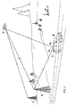
- Fig. 2 is an environmental view of a receiver system in accordance with one embodiment of the present invention.
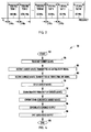
- Fig. 3 is a graph illustrating the down-conversion of a frequency of carrier waves in accordance with one embodiment of the present invention.
- Fig. 4 is a flow chart illustrating a method of communicating a plurality of carrier waves that are received by a single receiver system in accordance with one embodiment of the present invention.
- the receiver system 10 includes at least one antenna that receives a plurality of carrier waves.
- the at least one antenna includes a first antenna 12A and a second antenna 12B, where the first and second antennas 12A,12B are configured to receive different types of signals, as described in greater detail below.
- a single antenna may be employed to receive the plurality of carrier waves.
- the receiver system 10 also includes at least one splitter that is in communication with the antennas 12A,12B, and splits the received plurality of carrier waves.
- a first splitter 14A is in communication with the first antenna 12A
- a second splitter 14B is in communication with the second antenna 12B.
- the receiver system 10 includes a plurality of tuners 16 that are in communication with the first and second splitters 14A,14B, such that the split carrier waves are transmitted to a separate tuner 16.
- the tuners 16 are configured to separate the plurality of carrier waves, such that each tuner 16 processes only one carrier wave at a particular frequency.
- the receiver system 10 further includes at least one combiner 18 that is in communication with the tuners 16, and combines an output of each of the tuners 16.
- the receiver system 10 can also include a demodulator generally indicated at 20 that is in communication with the combiner 18 for demodulating the combined output of the combiner 18.
- the demodulator 20 can further include at least one analog-to-digital converter (ADC) 22 for converting the combined analog output of the combiner 18.
- ADC analog-to-digital converter
- the receiver system 10 emits an output 25 based upon the combined and demodulated signals. Thus, the output 25 is based upon at least a portion of the received plurality of carrier waves.
- the first antenna 12A is configured to receive the plurality of carrier waves that are transmitted as a satellite radio frequency (RF) signal
- the second antenna 12B is configured to receive the plurality of carrier waves that are transmitted as terrestrial RF signals.
- a transmitter 24 transmits or uplinks the satellite RF signal to a satellite 26.
- the satellite 26 then re-transmits or downlinks the satellite RF signal to the receiver system 10, which is shown located onboard a vehicle 30.
- the terrestrial repeater 28 receives the satellite RF signal from the satellite 24, and re-transmits the signal as a terrestrial RF signal.
- the first antenna 12A receives the satellite RF signal transmitted from the satellite 26, and the second antenna 12B receives the terrestrial RF signal transmitted by the terrestrial repeater 28.
- the satellite 26 is a highly elliptical orbit (HEO) satellite. It should be appreciated by those skilled in the art that more than one satellite and terrestrial repeaters may communicate signals to the receiver system 10.
- HEO highly elliptical orbit
- the signal received by the first antenna 12A is then communicated or transmitted to the first splitter 14A, and the signal received by the second antenna 12B is communicated or transmitted to the second splitter 14B.
- the first and second splitters 14A,14B split the plurality of carrier waves. It should be appreciated by those skilled in the art that any number of antennas and splitters can be used based upon the different types of signals being used to transmit the carrier waves.
- the plurality of split carrier waves are transmitted to the plurality of tuners 16, such that each tuner 16 in communication with a splitter 14A,14B receives all of the carrier waves received by the splitters 14A,14B.
- each tuner 16 filters different frequencies.
- a first tuner in communication with the second antenna 12B and the second splitter 14B can receive carrier waves at 1460 MHz and 1465 MHz
- a second tuner in communication with the second antenna 12B and second splitter 14B can filter the 1465 MHz to only process the 1460 MHz signal, and filter the 1460 MHz signal.
- the separate tuners 16 down-convert the frequency of the separated carrier wave, or the carrier wave that is not filtered, so that an output of the tuner 16 is at a lower frequency than the inputted separated carrier wave, as described in greater detail herein.
- any number of tuners 16 can be used based upon the number of carrier waves that are being received by the receiver system 10.
- the first and second splitters 14A,14B filter the carrier waves based upon which carrier wave is being communicated to each tuner 16.
- each individual tuner 16 is then transmitted or communicated to the combiner 18.
- the combiner 18 combines the output from each tuner 16, and transmits a combined output to the demodulator 20.
- the demodulator 20 then demodulates the combined output of the combiner 18 in order to produce an audio and/or video output. It should be appreciated by those skilled in the art that the demodulator 20 can also include any other desirable signal processing devices in order to produce the audio and/or video output 25.
- the receiver system 10 is configured to receive signals within the L-band frequency spectrum that typically ranges from 1450 MHz to 1490 MHz in one example.
- the receiver system 10 front end can be configured to receive the entire L-band frequencies of interest.
- the signal transmitted to the spot beam receiving areas includes two carrier waves
- the signal transmitted to the pan-European receiving area includes four carrier waves.
- the satellite RF signals are transmitted in a 1.712 MHz band
- the terrestrial RF signals are transmitted in a 1.536 MHz band.
- each tuner 16 is tuned to any of the possible L-band frequencies, and each tuner 16 has an RF local oscillator (LO) frequency that is selected in order to provide a common first intermediate frequency (IF) among the tuners 16.
- LO local oscillator
- the IF of a tuner 16 configured to receive a satellite signal from the first antenna 12A is 114.745 MHz and has an IF LO frequency of 115.713 MHz
- a second tuner 16 in communication with the first antenna 12A has an IF LO frequency of 117.499 MHz.
- the IF frequency is selected to provide the IF LO frequency.
- the satellite RF signals and terrestrial RF signals are down-converted by the tuners 16 to a lower frequency in order for the signal to fit within the baseband of the receiver system 10.
- the lower frequency allows for the signal to be communicated within the receiver system 10, and processed to produce the audio and/or video output 25.
- a tuner 16 in communication with the second antenna 12B and receives a terrestrial RF signal has an IF of .968 MHz
- a second tuner 16 in communication with the second antenna 12B has an IF of 2.704 MHz, where the signals communicated to both tuners 16 have a bandwidth of 1.536 MHz.
- the bandwidth of the second IF LO frequency signal is typically within the sampling rate of the single ADC 22, such that only one ADC 22 is needed. However, it should be appreciated by those skilled in the art that more than one ADC can be used.
- the receiver system 10 can receive signals within a spot beam receiving area, receive signals within the pan-European receiving area, detect signals within a spot beam receiving area, or a combination thereof.
- a method of communicating a plurality of carrier waves that are received by a single receiver system 10 is generally shown in Fig. 4 at reference identifier 100.
- the method 100 starts at step 102, and transmits the plurality of carrier waves by the transmitter 24 at step 104.
- the carrier waves that are transmitted as satellite RF signals are received by the first antenna 12A at step 106.
- the carrier waves that are transmitted as terrestrial RF signals are received by the second antenna 12B.
- the terrestrial repeater 28 receives a satellite RF signal from the satellite 26, and re-transmits the signal as a terrestrial RF signal that is received by the second antenna 12B.
- the method 100 then proceeds to step 110, where the received carrier waves are split by the first and second splitters 14A,14B.
- Each of the tuners 16 receives the desired carrier wave, with which the tuner 16 is configured to receive, and down-converts the frequency of the carrier waves at step 112.
- the combiner 18 combines the down-converted carrier waves that are outputted by the separate tuners 16.
- the demodulator 20 demodulates the combined output of the combiner 18 at step 116.
- the demodulator 20 then emits the audio and/or video output 25 at step 118, and the method 100 ends at step 120.
- the receiver system 10 can be located on a vehicle 30, as shown in Fig. 2 . As the vehicle 30 is mobile, the receiver system 10 can detect the signals being transmitted in a spot beam area. Further, the vehicle 30 needs only a single receiver system 10 to receive a plurality of carrier waves. However, it should be appreciated that the receiver system 10 can be used on mobile devices that are not used with the vehicle 10 and can be employed on stationary devices.
- the single receiver system 10 and method 100 allow for a plurality of carrier waves to be received without requiring multiple receivers, where a single receiver is needed for each carrier wave.
- a single receiver is needed for each carrier wave.
- the receiver system 10 can locate multiple types of signals, such as satellite RF signals and terrestrial RF signals, with which can be received.
Landscapes
- Engineering & Computer Science (AREA)
- Signal Processing (AREA)
- Computer Networks & Wireless Communication (AREA)
- Physics & Mathematics (AREA)
- Astronomy & Astrophysics (AREA)
- General Physics & Mathematics (AREA)
- Aviation & Aerospace Engineering (AREA)
- Radio Relay Systems (AREA)
- Input Circuits Of Receivers And Coupling Of Receivers And Audio Equipment (AREA)
- Circuits Of Receivers In General (AREA)
Abstract
Description
- The present invention generally relates to a system and method of communicating signals, and more particularly, to a system and method for receiving multiple carrier waves.
- There are a limited number of available frequencies for wirelessly transmitting data, and thus, the frequency bandwidths that are available for communication purposes are also limited. Since additional frequencies cannot be created, which would allow for additional communication, the available frequencies must be efficiently used. In the current European satellite radio systems, there are twenty-three (23) contiguous frequencies designated across forty megahertz (40 MHz), where only seven frequencies are designated for hybrid systems. Generally, hybrid systems include transmissions being broadcast using satellites and terrestrial transponders or terrestrial repeaters. The current European satellite radio system is constrained to frequency bandwidths of 1.712 MHz.
- Additionally, the current European satellite radio system is designed to have a pan-European receiving area and individual spot beam receiving areas in and around the pan-European receiving area. Generally, the pan-European and spot beam receiving areas have corresponding terrestrial repeaters. Typically, the signals transmitted to the pan-European and spot beam receiving areas include multiple carrier waves. Generally, a single receiver is needed to receive a single carrier wave, and thus, when multiple carrier waves are transmitted, multiple receivers are typically used.
- According to one aspect of the present invention, a receiver system includes at least one antenna, at least one splitter, a plurality of tuners, and at least one combiner. The at least one antenna receives a plurality of carrier waves. The
- at least one splitter is in communication with the at least one antenna, and splits the plurality of carrier waves. The plurality of tuners are in communication with the at least one splitter, and the split carrier waves are communicated to a separate tuner. The at least one combiner is in communication with the plurality of tuners, and combines an output of each of the plurality of tuners to generate an output based upon at least a portion of the received plurality of carrier waves.
- According to another aspect of the present invention, a receiver system includes a plurality of antennas, a plurality of splitters, a plurality of tuners, at least one combiner, and at least one demodulator. The plurality of antennas receive a plurality of carrier waves, and the plurality of antennas include at least a first antenna configured to receive at least a portion of the plurality of carrier waves that are transmitted as a satellite radio frequency (RF) signal, and a second antenna configured to receive at least a portion of the plurality of carrier waves transmitted as a terrestrial RF signal. The plurality of splitters are in communication with the antennas, and separate the plurality of carrier waves. The plurality of tuners are in communication with the splitters, and each of the separated carrier waves is communicated to a separate tuner. The at least one combiner is in communication with the tuners, and combines an output of the tuners. The at least one demodulator is in communication with the combiner and demodulates an output of the combiner to generate an output based upon at least a portion of the received plurality of carrier waves.
- According to yet another aspect of the present invention, a method of communicating the plurality of carrier waves that are received by a single receiver system includes the steps of transmitting the plurality of carrier waves, and receiving the plurality of carrier waves by a single receiver. The method further includes the steps of splitting the plurality of carrier waves, receiving a carrier wave by each of the plurality of tuners, down-converting a frequency of each of the separated carrier waves to a lower frequency by a plurality of tuners, and combining an output of each of the plurality of tuners to generate an output based upon at least a portion of the received plurality of carrier waves.
- These and other features, advantages and objects of the present invention will be further understood and appreciated by those skilled in the art by reference to the following specification, claims and appended drawings.
- The present invention will now be described, by way of example, with reference to the accompanying drawings, in which:
-
Fig. 1 is a block diagram of a receiver system in accordance with one embodiment of the present invention; -
Fig. 2 is an environmental view of a receiver system in accordance with one embodiment of the present invention; -
Fig. 3 is a graph illustrating the down-conversion of a frequency of carrier waves in accordance with one embodiment of the present invention; and -
Fig. 4 is a flow chart illustrating a method of communicating a plurality of carrier waves that are received by a single receiver system in accordance with one embodiment of the present invention. - In reference to both
Figs. 1 and2 , a receiver system is generally shown atreference identifier 10. Thereceiver system 10 includes at least one antenna that receives a plurality of carrier waves. According to one embodiment, the at least one antenna includes afirst antenna 12A and asecond antenna 12B, where the first andsecond antennas receiver system 10 also includes at least one splitter that is in communication with theantennas first splitter 14A is in communication with thefirst antenna 12A, and asecond splitter 14B is in communication with thesecond antenna 12B. - Additionally, the
receiver system 10 includes a plurality oftuners 16 that are in communication with the first andsecond splitters separate tuner 16. According to one embodiment, thetuners 16 are configured to separate the plurality of carrier waves, such that eachtuner 16 processes only one carrier wave at a particular frequency. Thereceiver system 10 further includes at least one combiner 18 that is in communication with thetuners 16, and combines an output of each of thetuners 16. Thereceiver system 10 can also include a demodulator generally indicated at 20 that is in communication with thecombiner 18 for demodulating the combined output of thecombiner 18. Thedemodulator 20 can further include at least one analog-to-digital converter (ADC) 22 for converting the combined analog output of thecombiner 18. Thereceiver system 10 emits anoutput 25 based upon the combined and demodulated signals. Thus, theoutput 25 is based upon at least a portion of the received plurality of carrier waves. - Typically, the
first antenna 12A is configured to receive the plurality of carrier waves that are transmitted as a satellite radio frequency (RF) signal, and thesecond antenna 12B is configured to receive the plurality of carrier waves that are transmitted as terrestrial RF signals. As shown inFig. 2 , atransmitter 24 transmits or uplinks the satellite RF signal to asatellite 26. Thesatellite 26 then re-transmits or downlinks the satellite RF signal to thereceiver system 10, which is shown located onboard avehicle 30. Additionally, theterrestrial repeater 28 receives the satellite RF signal from thesatellite 24, and re-transmits the signal as a terrestrial RF signal. In one embodiment, thefirst antenna 12A receives the satellite RF signal transmitted from thesatellite 26, and thesecond antenna 12B receives the terrestrial RF signal transmitted by theterrestrial repeater 28. According to a disclosed embodiment, thesatellite 26 is a highly elliptical orbit (HEO) satellite. It should be appreciated by those skilled in the art that more than one satellite and terrestrial repeaters may communicate signals to thereceiver system 10. - The signal received by the
first antenna 12A is then communicated or transmitted to thefirst splitter 14A, and the signal received by thesecond antenna 12B is communicated or transmitted to thesecond splitter 14B. The first andsecond splitters tuners 16, such that eachtuner 16 in communication with asplitter splitters - According to a disclosed embodiment, each
tuner 16 filters different frequencies. Thus, a first tuner in communication with thesecond antenna 12B and thesecond splitter 14B can receive carrier waves at 1460 MHz and 1465 MHz, and a second tuner in communication with thesecond antenna 12B andsecond splitter 14B can filter the 1465 MHz to only process the 1460 MHz signal, and filter the 1460 MHz signal. Typically, theseparate tuners 16 down-convert the frequency of the separated carrier wave, or the carrier wave that is not filtered, so that an output of thetuner 16 is at a lower frequency than the inputted separated carrier wave, as described in greater detail herein. It should further be appreciated by those skilled in the art that any number oftuners 16 can be used based upon the number of carrier waves that are being received by thereceiver system 10. According to an alternate embodiment, the first andsecond splitters tuner 16. - The output of each
individual tuner 16 is then transmitted or communicated to thecombiner 18. Thecombiner 18 combines the output from eachtuner 16, and transmits a combined output to thedemodulator 20. Thedemodulator 20 then demodulates the combined output of thecombiner 18 in order to produce an audio and/or video output. It should be appreciated by those skilled in the art that thedemodulator 20 can also include any other desirable signal processing devices in order to produce the audio and/orvideo output 25. - In reference to
Figs. 1-3 , by way of explanation and not limitation, thereceiver system 10 is configured to receive signals within the L-band frequency spectrum that typically ranges from 1450 MHz to 1490 MHz in one example. Thus, thereceiver system 10 front end can be configured to receive the entire L-band frequencies of interest. In the current European satellite radio system, the signal transmitted to the spot beam receiving areas includes two carrier waves, and the signal transmitted to the pan-European receiving area includes four carrier waves. Further, in the current European satellite radio system, the satellite RF signals are transmitted in a 1.712 MHz band, and the terrestrial RF signals are transmitted in a 1.536 MHz band. Typically, eachtuner 16 is tuned to any of the possible L-band frequencies, and eachtuner 16 has an RF local oscillator (LO) frequency that is selected in order to provide a common first intermediate frequency (IF) among thetuners 16. According to a disclosed embodiment, the IF of atuner 16 configured to receive a satellite signal from thefirst antenna 12A is 114.745 MHz and has an IF LO frequency of 115.713 MHz, and asecond tuner 16 in communication with thefirst antenna 12A has an IF LO frequency of 117.499 MHz. By having a common first IF, theindividual tuners 16 can have similar components, and thus, are not designed for specific frequencies. - As shown in
Fig. 3 , the IF frequency is selected to provide the IF LO frequency. Thus, the satellite RF signals and terrestrial RF signals are down-converted by thetuners 16 to a lower frequency in order for the signal to fit within the baseband of thereceiver system 10. The lower frequency allows for the signal to be communicated within thereceiver system 10, and processed to produce the audio and/orvideo output 25. According to a disclosed embodiment, atuner 16 in communication with thesecond antenna 12B and receives a terrestrial RF signal has an IF of .968 MHz, and asecond tuner 16 in communication with thesecond antenna 12B has an IF of 2.704 MHz, where the signals communicated to bothtuners 16 have a bandwidth of 1.536 MHz. Further, the bandwidth of the second IF LO frequency signal is typically within the sampling rate of thesingle ADC 22, such that only oneADC 22 is needed. However, it should be appreciated by those skilled in the art that more than one ADC can be used. Thus, thereceiver system 10 can receive signals within a spot beam receiving area, receive signals within the pan-European receiving area, detect signals within a spot beam receiving area, or a combination thereof. - With particular reference to
Figs. 1-2 and4 , a method of communicating a plurality of carrier waves that are received by asingle receiver system 10 is generally shown inFig. 4 atreference identifier 100. Themethod 100 starts atstep 102, and transmits the plurality of carrier waves by thetransmitter 24 atstep 104. The carrier waves that are transmitted as satellite RF signals are received by thefirst antenna 12A atstep 106. Atstep 108, the carrier waves that are transmitted as terrestrial RF signals are received by thesecond antenna 12B. Thus, theterrestrial repeater 28 receives a satellite RF signal from thesatellite 26, and re-transmits the signal as a terrestrial RF signal that is received by thesecond antenna 12B. - The
method 100 then proceeds to step 110, where the received carrier waves are split by the first andsecond splitters tuners 16 receives the desired carrier wave, with which thetuner 16 is configured to receive, and down-converts the frequency of the carrier waves atstep 112. Atstep 114, thecombiner 18 combines the down-converted carrier waves that are outputted by theseparate tuners 16. Thedemodulator 20 demodulates the combined output of thecombiner 18 atstep 116. Thedemodulator 20 then emits the audio and/orvideo output 25 atstep 118, and themethod 100 ends atstep 120. - By way of explanation and not limitation, the
receiver system 10 can be located on avehicle 30, as shown inFig. 2 . As thevehicle 30 is mobile, thereceiver system 10 can detect the signals being transmitted in a spot beam area. Further, thevehicle 30 needs only asingle receiver system 10 to receive a plurality of carrier waves. However, it should be appreciated that thereceiver system 10 can be used on mobile devices that are not used with thevehicle 10 and can be employed on stationary devices. - Advantageously, the
single receiver system 10 andmethod 100 allow for a plurality of carrier waves to be received without requiring multiple receivers, where a single receiver is needed for each carrier wave. Thus, in the current European satellite radio system, for example, where multiple carrier waves are being used in the spot beam and pan-European receiving areas, one would have to have multiple receivers for each of the carrier waves. Further, by combining the output with thecombiner 18, only asingle ADC 22 is required, and thus, being more economical than if multiple ADCs were used. Additionally, having thefirst antenna 12A andsecond antenna 12B being configured to receive different types of signals, thereceiver system 10 can locate multiple types of signals, such as satellite RF signals and terrestrial RF signals, with which can be received. - The above description is considered that of the preferred embodiments only. Modifications of the invention will occur to those skilled in the art and to those who make or use the invention. Therefore, it is understood that the embodiments shown in the drawings and described above are merely for illustrative purposes and not intended to limit the scope of the invention, which is defined by the following claims as interpreted according to the principles of patent law, including the doctrine of equivalents.
Claims (20)
- A receiver system (10) comprising:at least one antenna that receives a plurality of carrier waves;at least one splitter in communication with said at least one antenna, wherein said at least one splitter splits said plurality of carrier waves;a plurality of tuners (16) in communication with said at least one splitter, wherein said split carrier waves are communicated to a separate tuner (16) of said plurality of tuners (16); andat least one combiner (18) in communication with each of said plurality of tuners (16), wherein said at least one combiner (18) combines an output of each of said plurality of tuners (16) to generate an output based upon at least a portion of said received plurality of carrier waves.
- The receiver system (10) of claim 1 further comprising at least one demodulator (20) in communication with said at least one combiner (18), wherein said at least one demodulator (20) demodulates a combined output of the at least one combiner (18).
- The receiver system (10) of claim 2, wherein said at least one demodulator (20) comprises at least one analog-to-digital converter (ADC) (22).
- The receiver system (10) of claim 1, wherein said plurality of tuners (16) down-converts a frequency of said separated carrier wave so that said output is at a lower frequency.
- The receiver system (10) of claim 1, wherein a first antenna (12A) of said at least one antenna is configured to receive at least a portion of said plurality of carrier waves transmitted as a satellite radio frequency (RF) signal and are transmitted to a first splitter (14A) of said at least one splitter.
- The receiver system (10) of claim 1, wherein a second antenna (12B) of said at least one antenna is configured to receive at least a portion of said plurality of carrier waves transmitted as a terrestrial RF signal and are transmitted to a second splitter (14B) of said at least one splitter.
- The receiver system (10) of claim 1, wherein said plurality of tuners (16) include two to six tuners.
- The receiver system (10) of claim 1, wherein said receiver system (10) is located on a vehicle (30).
- A receiver system (10) comprising:a plurality of antennas that receive a plurality of carrier waves, wherein said plurality of antennas include at least a first antenna (12A) of said plurality of antennas configured to receive at least a portion of said plurality of carrier waves transmitted as a satellite radio frequency (RF) signal and a second antenna (12B) of said plurality of antennas configured to receive at least a portion of said plurality of carrier waves transmitted as a terrestrial RF signal;a plurality of splitters in communication with said plurality of antennas, wherein said plurality of splitters separate said plurality of carrier waves;a plurality of tuners (16) in communication with said plurality of splitters, wherein each said separated carrier wave is communicated to a separate tuner (16) of said plurality of tuners (16);at least one combiner (18) is communication with each of said plurality of tuners (16), wherein said at least one combiner (18) combines an output of each of said plurality of tuners (16); andat least one demodulator (20) in communication with said at least one combiner (18), wherein said at least one demodulator (20) combines an output of said at least one combiner (18) to generate an output based upon at least a portion of said received plurality of carrier waves.
- The receiver system (10) of claim 9, wherein said at least one demodulator (20) comprises at least one analog-to-digital converter (ADC) (22).
- The receiver system (10) of claim 9, wherein said plurality of tuners (16) down-converts a frequency of said separated carrier wave so that said output is at a lower frequency.
- The receiver system (10) of claim 9, wherein said plurality of tuners (16) include two to six tuners (16).
- The receiver system (10) of claim 9, wherein said satellite RF signal is transmitted to a first splitter (14A) of said plurality of splitters, and said terrestrial RF signal is transmitted to a second splitter (14B) of said plurality of splitters.
- The receiver system (10) of claim 9, wherein said receiver system (10) is located on a vehicle (30).
- A method of communicating a plurality of carrier waves (100) that are received by a single receiver system (10), said method (100) comprising the steps of:transmitting said plurality of carrier waves (104);receiving said plurality of carrier waves (106,108) by said single receiver;splitting said plurality of carrier waves (110);receiving a carrier wave by each of said plurality of tuners (16);down-converting (112) a frequency of each said separated carrier wave to a lower frequency by a plurality of tuners (16); andcombining (114) an output of each of said plurality of tuners (16) to generate an output based upon at least a portion of said received plurality of carrier waves.
- The method (100) of claim 15 further comprising the step of demodulating (116) said combined output by a demodulator (20).
- The method (100) of claim 16 further comprising the step of analog-to-digital converting said combined output by said demodulator (20).
- The method (100) of claim 15, wherein said plurality of carrier waves are received by a plurality of antennas that include at least a first antenna (14A) of said plurality of antennas configured to receive at least a portion of said plurality of carrier waves transmitted as a satellite radio frequency (RF) signal and a second antenna (14B) of said plurality of antennas configured to receive at least a portion of said plurality of carrier waves transmitted as a terrestrial RF signal.
- The method (100) of claim 18, wherein said plurality of carrier waves are split by a plurality of splitters that includes at least a first splitter (14A) of said plurality of splitters that receives said satellite RF signals and a second splitter (14B) of said plurality of splitters that receives said terrestrial RF signals.
- The method (100) of claim 15, wherein said receiver system (10) is located on a vehicle (30).
Applications Claiming Priority (1)
| Application Number | Priority Date | Filing Date | Title |
|---|---|---|---|
| US11/824,020 US8032100B2 (en) | 2007-06-29 | 2007-06-29 | System and method of communicating multiple carrier waves |
Publications (2)
| Publication Number | Publication Date |
|---|---|
| EP2009816A2 true EP2009816A2 (en) | 2008-12-31 |
| EP2009816A3 EP2009816A3 (en) | 2014-07-02 |
Family
ID=39639796
Family Applications (1)
| Application Number | Title | Priority Date | Filing Date |
|---|---|---|---|
| EP08157805.6A Withdrawn EP2009816A3 (en) | 2007-06-29 | 2008-06-06 | System and method of communicating multiple carrier waves |
Country Status (2)
| Country | Link |
|---|---|
| US (1) | US8032100B2 (en) |
| EP (1) | EP2009816A3 (en) |
Families Citing this family (1)
| Publication number | Priority date | Publication date | Assignee | Title |
|---|---|---|---|---|
| US12081247B2 (en) * | 2019-09-26 | 2024-09-03 | Altera Corporation | Systems and methods for electronically scanned array antennas |
Family Cites Families (28)
| Publication number | Priority date | Publication date | Assignee | Title |
|---|---|---|---|---|
| US4017859A (en) * | 1975-12-22 | 1977-04-12 | The United States Of America As Represented By The Secretary Of The Navy | Multi-path signal enhancing apparatus |
| US4347627A (en) * | 1979-02-26 | 1982-08-31 | E-Systems, Inc. | Adaptive array processor and processing method for communication system |
| DE3634439A1 (en) * | 1986-10-09 | 1988-04-14 | Blaupunkt Werke Gmbh | METHOD AND CIRCUIT FOR RECEIVING RADIO WAVES |
| US4733402A (en) * | 1987-04-23 | 1988-03-22 | Signatron, Inc. | Adaptive filter equalizer systems |
| EP0610313B1 (en) * | 1991-11-01 | 1998-02-04 | Thomson Consumer Electronics Sales GmbH | Radio transmission system and radio receiver |
| US5627879A (en) * | 1992-09-17 | 1997-05-06 | Adc Telecommunications, Inc. | Cellular communications system with centralized base stations and distributed antenna units |
| DE69327837T2 (en) * | 1992-12-01 | 2000-10-12 | Koninklijke Philips Electronics N.V., Eindhoven | Subband diversity transmission system |
| JPH08511135A (en) * | 1993-06-03 | 1996-11-19 | ドイチエ トムソン−ブラント ゲゼルシヤフト ミツト ベシユレンクテル ハフツング | Television tuner for terrestrial and satellite reception |
| US5859874A (en) * | 1994-05-09 | 1999-01-12 | Globalstar L.P. | Multipath communication system optimizer |
| US5745846A (en) * | 1995-08-07 | 1998-04-28 | Lucent Technologies, Inc. | Channelized apparatus for equalizing carrier powers of multicarrier signal |
| US5805108A (en) * | 1996-09-16 | 1998-09-08 | Trimble Navigation Limited | Apparatus and method for processing multiple frequencies in satellite navigation systems |
| JP3381580B2 (en) * | 1996-11-22 | 2003-03-04 | 株式会社豊田中央研究所 | Adaptive communication device |
| JP3657377B2 (en) * | 1996-12-27 | 2005-06-08 | 松下電器産業株式会社 | Receiver circuit |
| US6944139B1 (en) * | 1998-03-27 | 2005-09-13 | Worldspace Management Corporation | Digital broadcast system using satellite direct broadcast and terrestrial repeater |
| US6128330A (en) * | 1998-11-24 | 2000-10-03 | Linex Technology, Inc. | Efficient shadow reduction antenna system for spread spectrum |
| US6151328A (en) * | 1998-12-31 | 2000-11-21 | Lg Information & Communications Ltd. | Apparatus and method for controlling power in code division multiple access system |
| US6724827B1 (en) * | 1999-05-25 | 2004-04-20 | Xm Satellite Radio, Inc. | Low cost interoperable satellite digital audio radio service (SDARS) receiver adapted to receive signals in accordance with advantageous frequency plan |
| US6466558B1 (en) * | 1999-06-14 | 2002-10-15 | Qualcomm Incorporated | Selection mechanism for signal combining methods |
| US6285861B1 (en) * | 1999-06-14 | 2001-09-04 | Qualcomm Incorporated | Receiving station with interference signal suppression |
| US6549774B1 (en) * | 1999-11-04 | 2003-04-15 | Xm Satellite Radio Inc. | Digital audio service satellite receiver having switchable operating modes for stationary or mobile use |
| GB0117591D0 (en) * | 2001-07-18 | 2001-09-12 | Zarlink Semiconductor Ltd | Television tuner |
| US20040022326A1 (en) * | 2002-07-30 | 2004-02-05 | John Morrish | Digital audio receiver |
| US7747229B2 (en) * | 2004-11-19 | 2010-06-29 | Atc Technologies, Llc | Electronic antenna beam steering using ancillary receivers and related methods |
| US7848458B2 (en) * | 2005-02-18 | 2010-12-07 | Mitsubishi Electric Corporation | Communication apparatus |
| US7623594B2 (en) * | 2005-02-28 | 2009-11-24 | Delphi Technologies, Inc. | Satellite receiver system |
| US7778335B2 (en) * | 2005-04-22 | 2010-08-17 | Xm Satellite Radio, Inc. | Method and system for hierarchical modulation and demodulation for digital radio |
| WO2007084681A1 (en) * | 2006-01-20 | 2007-07-26 | Atc Technologies, Llc | Systems and methods for satellite forward link transmit diversity using orthogonal space coding |
| US20080287163A1 (en) * | 2007-05-17 | 2008-11-20 | Telefonaktiebolaget Lm Ericsson (Publ), | Method and apparatus for converting between a multi-sector, omni-base station configuration and a multi-sector base station configuration |
-
2007
- 2007-06-29 US US11/824,020 patent/US8032100B2/en active Active
-
2008
- 2008-06-06 EP EP08157805.6A patent/EP2009816A3/en not_active Withdrawn
Also Published As
| Publication number | Publication date |
|---|---|
| US8032100B2 (en) | 2011-10-04 |
| US20090004970A1 (en) | 2009-01-01 |
| EP2009816A3 (en) | 2014-07-02 |
Similar Documents
| Publication | Publication Date | Title |
|---|---|---|
| US8711993B2 (en) | Wideband multi-channel receiver with fixed-frequency notch filter for interference rejection | |
| US6510317B1 (en) | Satellite digital audio radio service tuner architecture for reception of satellite and terrestrial signals | |
| EP2546678B1 (en) | Multichannel, multimode, multifunction L-band radio transreceiver | |
| US20050094750A1 (en) | Demodulation apparatus and method for reducing time delay of on-channel repeater in terrestrial digital TV broadcasting system | |
| US7605757B1 (en) | Multiple signal receiver | |
| US9363116B2 (en) | Multi-standard front end using wideband data converters | |
| US6724827B1 (en) | Low cost interoperable satellite digital audio radio service (SDARS) receiver adapted to receive signals in accordance with advantageous frequency plan | |
| CN101123440A (en) | Direct RF digitalizing method for multiple RF frequency bands and receiver thereof | |
| US7756473B2 (en) | Apparatus and method of on-channel repeater | |
| US11456800B2 (en) | Systems and methods for communicating data over satellites | |
| US20090174602A1 (en) | Dvor monitor device, and dvor monitor method | |
| US7301994B2 (en) | Modulation apparatus for reducing time delay of on-channel repeater in terrestrial digital TV broadcasting system | |
| US8032100B2 (en) | System and method of communicating multiple carrier waves | |
| US7720434B2 (en) | Method and system for processing GPS and satellite digital radio signals using a shared LNA | |
| US20090221285A1 (en) | Communications system | |
| US6643509B1 (en) | Civil aviation communication system | |
| EP1830499A2 (en) | Receiver for receiving digital satellite signals and method for expanding the coverage of digital satellite radio for reception devices | |
| US6745005B1 (en) | Method and apparatus for reducing signal interference in satellite broadcast systems employing terrestrial repeater stations | |
| US20120082275A1 (en) | Combined satellite radio receiver | |
| EP2190134B1 (en) | Communication system and method of communicating signals | |
| RU2562423C2 (en) | Method and system for receiving signals from radio station | |
| KR101415476B1 (en) | Device and method for receiving signals of multi band | |
| KR101007394B1 (en) | Receiver in Frequency Division Duplex System | |
| US20070053314A1 (en) | Method and apparatus for providing satellite television and other data to mobile antennas | |
| US20080293359A1 (en) | System and method of communicating and re-using frequencies within terrestrial and satellite signal paths |
Legal Events
| Date | Code | Title | Description |
|---|---|---|---|
| PUAI | Public reference made under article 153(3) epc to a published international application that has entered the european phase |
Free format text: ORIGINAL CODE: 0009012 |
|
| AK | Designated contracting states |
Kind code of ref document: A2 Designated state(s): AT BE BG CH CY CZ DE DK EE ES FI FR GB GR HR HU IE IS IT LI LT LU LV MC MT NL NO PL PT RO SE SI SK TR |
|
| AX | Request for extension of the european patent |
Extension state: AL BA MK RS |
|
| RAP1 | Party data changed (applicant data changed or rights of an application transferred) |
Owner name: TAB TWO LIMITED LIABILITY COMPANY |
|
| PUAL | Search report despatched |
Free format text: ORIGINAL CODE: 0009013 |
|
| AK | Designated contracting states |
Kind code of ref document: A3 Designated state(s): AT BE BG CH CY CZ DE DK EE ES FI FR GB GR HR HU IE IS IT LI LT LU LV MC MT NL NO PL PT RO SE SI SK TR |
|
| AX | Request for extension of the european patent |
Extension state: AL BA MK RS |
|
| RIC1 | Information provided on ipc code assigned before grant |
Ipc: H04H 40/90 20080101ALI20140523BHEP Ipc: H04B 7/185 20060101AFI20140523BHEP Ipc: H04B 7/08 20060101ALI20140523BHEP |
|
| AKY | No designation fees paid | ||
| AXX | Extension fees paid |
Extension state: RS Extension state: AL Extension state: BA Extension state: MK |
|
| REG | Reference to a national code |
Ref country code: DE Ref legal event code: R108 |
|
| REG | Reference to a national code |
Ref country code: DE Ref legal event code: R108 Effective date: 20150311 |
|
| STAA | Information on the status of an ep patent application or granted ep patent |
Free format text: STATUS: THE APPLICATION IS DEEMED TO BE WITHDRAWN |
|
| 18D | Application deemed to be withdrawn |
Effective date: 20150106 |