EP2009734A1 - Vehicular glass-mounted Antenna and System - Google Patents
Vehicular glass-mounted Antenna and System Download PDFInfo
- Publication number
- EP2009734A1 EP2009734A1 EP08163677A EP08163677A EP2009734A1 EP 2009734 A1 EP2009734 A1 EP 2009734A1 EP 08163677 A EP08163677 A EP 08163677A EP 08163677 A EP08163677 A EP 08163677A EP 2009734 A1 EP2009734 A1 EP 2009734A1
- Authority
- EP
- European Patent Office
- Prior art keywords
- antenna
- windshield glass
- glass
- antennas
- antenna unit
- Prior art date
- Legal status (The legal status is an assumption and is not a legal conclusion. Google has not performed a legal analysis and makes no representation as to the accuracy of the status listed.)
- Withdrawn
Links
- 239000011521 glass Substances 0.000 claims abstract description 67
- 230000010363 phase shift Effects 0.000 claims abstract description 7
- 238000001465 metallisation Methods 0.000 description 19
- 230000005855 radiation Effects 0.000 description 10
- 239000002985 plastic film Substances 0.000 description 8
- 229920006255 plastic film Polymers 0.000 description 8
- 230000008878 coupling Effects 0.000 description 5
- 238000010168 coupling process Methods 0.000 description 5
- 238000005859 coupling reaction Methods 0.000 description 5
- 229910052751 metal Inorganic materials 0.000 description 5
- 239000002184 metal Substances 0.000 description 5
- 239000000463 material Substances 0.000 description 4
- 239000004033 plastic Substances 0.000 description 4
- 230000010287 polarization Effects 0.000 description 4
- 230000005540 biological transmission Effects 0.000 description 2
- 230000009977 dual effect Effects 0.000 description 2
- 230000005284 excitation Effects 0.000 description 2
- 238000000034 method Methods 0.000 description 2
- IRLPACMLTUPBCL-KQYNXXCUSA-N 5'-adenylyl sulfate Chemical compound C1=NC=2C(N)=NC=NC=2N1[C@@H]1O[C@H](COP(O)(=O)OS(O)(=O)=O)[C@@H](O)[C@H]1O IRLPACMLTUPBCL-KQYNXXCUSA-N 0.000 description 1
- BQCADISMDOOEFD-UHFFFAOYSA-N Silver Chemical compound [Ag] BQCADISMDOOEFD-UHFFFAOYSA-N 0.000 description 1
- 239000000853 adhesive Substances 0.000 description 1
- 230000001070 adhesive effect Effects 0.000 description 1
- 230000001413 cellular effect Effects 0.000 description 1
- 238000004891 communication Methods 0.000 description 1
- 230000000295 complement effect Effects 0.000 description 1
- 239000004020 conductor Substances 0.000 description 1
- 238000005336 cracking Methods 0.000 description 1
- 239000003989 dielectric material Substances 0.000 description 1
- 238000005562 fading Methods 0.000 description 1
- AMGQUBHHOARCQH-UHFFFAOYSA-N indium;oxotin Chemical compound [In].[Sn]=O AMGQUBHHOARCQH-UHFFFAOYSA-N 0.000 description 1
- 239000000203 mixture Substances 0.000 description 1
- 238000012544 monitoring process Methods 0.000 description 1
- 229910052709 silver Inorganic materials 0.000 description 1
- 239000004332 silver Substances 0.000 description 1
- 239000007787 solid Substances 0.000 description 1
- 239000013589 supplement Substances 0.000 description 1
Images

Classifications
-
- H—ELECTRICITY
- H01—ELECTRIC ELEMENTS
- H01Q—ANTENNAS, i.e. RADIO AERIALS
- H01Q1/00—Details of, or arrangements associated with, antennas
- H01Q1/12—Supports; Mounting means
- H01Q1/1271—Supports; Mounting means for mounting on windscreens
- H01Q1/1285—Supports; Mounting means for mounting on windscreens with capacitive feeding through the windscreen
-
- B—PERFORMING OPERATIONS; TRANSPORTING
- B32—LAYERED PRODUCTS
- B32B—LAYERED PRODUCTS, i.e. PRODUCTS BUILT-UP OF STRATA OF FLAT OR NON-FLAT, e.g. CELLULAR OR HONEYCOMB, FORM
- B32B17/00—Layered products essentially comprising sheet glass, or glass, slag, or like fibres
- B32B17/06—Layered products essentially comprising sheet glass, or glass, slag, or like fibres comprising glass as the main or only constituent of a layer, next to another layer of a specific material
- B32B17/10—Layered products essentially comprising sheet glass, or glass, slag, or like fibres comprising glass as the main or only constituent of a layer, next to another layer of a specific material of synthetic resin
- B32B17/10005—Layered products essentially comprising sheet glass, or glass, slag, or like fibres comprising glass as the main or only constituent of a layer, next to another layer of a specific material of synthetic resin laminated safety glass or glazing
- B32B17/10009—Layered products essentially comprising sheet glass, or glass, slag, or like fibres comprising glass as the main or only constituent of a layer, next to another layer of a specific material of synthetic resin laminated safety glass or glazing characterized by the number, the constitution or treatment of glass sheets
- B32B17/10036—Layered products essentially comprising sheet glass, or glass, slag, or like fibres comprising glass as the main or only constituent of a layer, next to another layer of a specific material of synthetic resin laminated safety glass or glazing characterized by the number, the constitution or treatment of glass sheets comprising two outer glass sheets
-
- B—PERFORMING OPERATIONS; TRANSPORTING
- B32—LAYERED PRODUCTS
- B32B—LAYERED PRODUCTS, i.e. PRODUCTS BUILT-UP OF STRATA OF FLAT OR NON-FLAT, e.g. CELLULAR OR HONEYCOMB, FORM
- B32B17/00—Layered products essentially comprising sheet glass, or glass, slag, or like fibres
- B32B17/06—Layered products essentially comprising sheet glass, or glass, slag, or like fibres comprising glass as the main or only constituent of a layer, next to another layer of a specific material
- B32B17/10—Layered products essentially comprising sheet glass, or glass, slag, or like fibres comprising glass as the main or only constituent of a layer, next to another layer of a specific material of synthetic resin
- B32B17/10005—Layered products essentially comprising sheet glass, or glass, slag, or like fibres comprising glass as the main or only constituent of a layer, next to another layer of a specific material of synthetic resin laminated safety glass or glazing
- B32B17/10165—Functional features of the laminated safety glass or glazing
- B32B17/10174—Coatings of a metallic or dielectric material on a constituent layer of glass or polymer
-
- B—PERFORMING OPERATIONS; TRANSPORTING
- B60—VEHICLES IN GENERAL
- B60C—VEHICLE TYRES; TYRE INFLATION; TYRE CHANGING; CONNECTING VALVES TO INFLATABLE ELASTIC BODIES IN GENERAL; DEVICES OR ARRANGEMENTS RELATED TO TYRES
- B60C23/00—Devices for measuring, signalling, controlling, or distributing tyre pressure or temperature, specially adapted for mounting on vehicles; Arrangement of tyre inflating devices on vehicles, e.g. of pumps or of tanks; Tyre cooling arrangements
- B60C23/02—Signalling devices actuated by tyre pressure
- B60C23/04—Signalling devices actuated by tyre pressure mounted on the wheel or tyre
- B60C23/0408—Signalling devices actuated by tyre pressure mounted on the wheel or tyre transmitting the signals by non-mechanical means from the wheel or tyre to a vehicle body mounted receiver
- B60C23/0422—Signalling devices actuated by tyre pressure mounted on the wheel or tyre transmitting the signals by non-mechanical means from the wheel or tyre to a vehicle body mounted receiver characterised by the type of signal transmission means
- B60C23/0433—Radio signals
- B60C23/0435—Vehicle body mounted circuits, e.g. transceiver or antenna fixed to central console, door, roof, mirror or fender
- B60C23/0444—Antenna structures, control or arrangements thereof, e.g. for directional antennas, diversity antenna, antenna multiplexing or antennas integrated in fenders
-
- H—ELECTRICITY
- H01—ELECTRIC ELEMENTS
- H01Q—ANTENNAS, i.e. RADIO AERIALS
- H01Q1/00—Details of, or arrangements associated with, antennas
- H01Q1/27—Adaptation for use in or on movable bodies
- H01Q1/32—Adaptation for use in or on road or rail vehicles
- H01Q1/3208—Adaptation for use in or on road or rail vehicles characterised by the application wherein the antenna is used
- H01Q1/3233—Adaptation for use in or on road or rail vehicles characterised by the application wherein the antenna is used particular used as part of a sensor or in a security system, e.g. for automotive radar, navigation systems
-
- H—ELECTRICITY
- H01—ELECTRIC ELEMENTS
- H01Q—ANTENNAS, i.e. RADIO AERIALS
- H01Q1/00—Details of, or arrangements associated with, antennas
- H01Q1/27—Adaptation for use in or on movable bodies
- H01Q1/32—Adaptation for use in or on road or rail vehicles
- H01Q1/325—Adaptation for use in or on road or rail vehicles characterised by the location of the antenna on the vehicle
-
- H—ELECTRICITY
- H01—ELECTRIC ELEMENTS
- H01Q—ANTENNAS, i.e. RADIO AERIALS
- H01Q21/00—Antenna arrays or systems
- H01Q21/24—Combinations of antenna units polarised in different directions for transmitting or receiving circularly and elliptically polarised waves or waves linearly polarised in any direction
-
- H—ELECTRICITY
- H01—ELECTRIC ELEMENTS
- H01Q—ANTENNAS, i.e. RADIO AERIALS
- H01Q9/00—Electrically-short antennas having dimensions not more than twice the operating wavelength and consisting of conductive active radiating elements
- H01Q9/04—Resonant antennas
-
- H—ELECTRICITY
- H01—ELECTRIC ELEMENTS
- H01Q—ANTENNAS, i.e. RADIO AERIALS
- H01Q9/00—Electrically-short antennas having dimensions not more than twice the operating wavelength and consisting of conductive active radiating elements
- H01Q9/04—Resonant antennas
- H01Q9/0407—Substantially flat resonant element parallel to ground plane, e.g. patch antenna
- H01Q9/0414—Substantially flat resonant element parallel to ground plane, e.g. patch antenna in a stacked or folded configuration
-
- H—ELECTRICITY
- H01—ELECTRIC ELEMENTS
- H01Q—ANTENNAS, i.e. RADIO AERIALS
- H01Q9/00—Electrically-short antennas having dimensions not more than twice the operating wavelength and consisting of conductive active radiating elements
- H01Q9/04—Resonant antennas
- H01Q9/0407—Substantially flat resonant element parallel to ground plane, e.g. patch antenna
- H01Q9/0428—Substantially flat resonant element parallel to ground plane, e.g. patch antenna radiating a circular polarised wave
Definitions
- the present invention generally relates to vehicular glass-mount antennas having improved radiation characteristics.
- AM/FM amplitude modulation / frequency modulation
- SDARS satellite digital audio radio systems
- GPS global positioning system
- DAB digital audio broadcast
- PCS/AMPS dual-band personal communication systems digital/analog mobile phone service
- RKE Remote Keyless Entry
- Tire Pressure Monitoring System antennas, and other wireless systems.
- patch antennas are employed for reception and transmission of GPS [i.e. right-hand-circular-polarization (RHCP) waves] and SDARS [i.e. left-hand-circular-polarization (LHCP) waves].
- Patch antennas may be considered to be a 'single element' antenna that incorporates performance characteristics of 'dual element' antennas that essentially receives terrestrial and satellite signals.
- SDARS for example, offer digital radio service covering a large geographic area, such as North America.
- Satellite-based digital audio radio services generally employ either geo-stationary orbit satellites or highly elliptical orbit satellites that receive uplinked programming, which, in turn, is re-broadcasted directly to digital radios in vehicles on the ground that subscribe to the service.
- SDARS also use terrestrial repeater networks via ground-based towers using different modulation and transmission techniques in urban areas to supplement the availability of satellite broadcasting service by terrestrially broadcasting the same information.
- the reception of signals from ground-based broadcast stations is termed as terrestrial coverage.
- an SDARS antenna is required to have satellite and terrestrial coverage with reception quality determined by the service providers, and each vehicle subscribing to the digital service generally includes a digital radio having a receiver and one or more antennas for receiving the digital broadcast.
- GPS antennas on the other hand, have a broad hemispherical coverage with a maximum antenna gain at the zenith (i.e. hemispherical coverage includes signals from 0 0 elevation at the earth's surface to signals from 90° elevation up at the sky).
- Emergency systems that utilize GPS such as OnStar TM , tend to have more stringent antenna specifications.
- SDARS patch antennas are operated at higher frequency bands and presently track only two satellites at a time.
- the mounting location for SDARS patch antennas makes antenna reception a sensitive issue with respect to the position of the antenna on a vehicle.
- SDARS patch antennas are typically mounted exterior to the vehicle, usually on the roof, or alternatively, inside the vehicle in a hidden location, for example, within an instrument panel.
- such as cellular telephone mast antennas have been located on the exterior surface of automotive glass and the received signals are electromagnetically coupled through the glass to the vehicle's receiver.
- Electromagnetically coupling such antennas in an SDARS application, without an external amplifier, is very difficult due to inherent loss and distorted radiation patterns associated with front windshield glass composition, which includes an intermediate plastic layer sandwiched between inner and outer glass layers. Additionally, external antennas are highly visible, prone to being damaged, and not aesthetically pleasing.
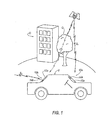
- Figure 1 illustrates a general side view of the vehicle glass mount antenna system
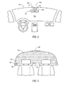
- Figure 2 illustrates a passenger compartment view of a front windshield glass mount antenna according to one embodiment of the invention
- Figure 3 illustrates a passenger compartment view of a rear glass mount antenna according to one embodiment of the invention
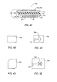
- Figure 4A illustrates a cross-sectional view of the front windshield glass mount antenna according to one embodiment of the invention
- Figure 4B illustrates a top view of an embodiment of a first element of the front windshield glass mount antenna according to Figure 4A ;
- Figure 4C illustrates a top view of an embodiment of a second element of the front windshield glass mount antenna according to Figure 4A ;
- Figure 4D illustrates a top view of another embodiment of a first element of the front windshield glass mount antenna according to Figure 4A ;
- Figure 4E illustrates a top view of another embodiment of a second element of the front windshield glass mount antenna according to Figure 4A ;
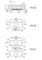
- Figure 5A illustrates a cross-sectional view of the rear windshield glass mount antenna according to one embodiment of the invention
- Figure 5B illustrates an embodiment of a schematic top view of the rear windshield glass mount antenna according to Figure 5A ;
- Figure 5C illustrates another embodiment of a schematic top view of the rear windshield glass mount antenna according to Figure 5A ;
- Figure 6A illustrates a cross-sectional view of a rear-view mirror assembly and the front windshield glass mount antenna according to one embodiment of the invention
- Figure 6B illustrates a cross-sectional view of a rear-view mirror assembly and the front windshield glass mount antenna according to another embodiment of the invention
- Figure 7A illustrates a cross-sectional view of the front windshield glass mount antenna according to another embodiment of the invention.
- Figure 7B illustrates a cross-sectional view of the front windshield glass mount antenna according to another embodiment of the invention.
- Figure 8A illustrates a cross-sectional view of the front windshield glass mount antenna according to another embodiment of the invention.
- Figure 8B illustrates a cross-sectional view of the front windshield glass mount antenna according to another embodiment of the invention.
- a vehicle includes a front windshield glass 12a and rear windshield glass 12b each including antenna units 14a, 14b, respectively.
- the antenna unit 14a is shown proximate a rear-view mirror assembly 13 at a top portion 15 of the front windshield glass 12a that meets a headliner (not shown). The location of headliner provides the shortest path to route and hide wires 16 extending from the antenna unit 14a and rear-view mirror assembly 13.
- the antenna unit 14a When implemented near the top portion 15, the antenna unit 14a should not come into direct contact with the vehicle body so as to ensure that the antenna unit 14a is not shorted out.
- the antenna unit 14b is located near a corner 18 of the rear windshield glass 12b such that defroster wires 19 are routed about the mounting location of the antenna unit 14b.
- the antenna unit 14b is shown near the corner 18, the antenna unit 14b can be located at any desirable location on the rear windshield glass, but more preferably, in a location that is less visible to the passengers and driver.
- the antenna unit 14b may be located between the rear windshield glass 12b and a rear brake light housing 21 so as to completely hide the antenna unit 14b from the passengers and driver.
- the front windshield glass 12a ( Figure 4A ) includes a layer of plastic film 11c that is sandwiched between an outer glass layer 11a and an inner glass layer 11b, whereas, conversely, the rear windshield glass 12b ( Figure 5A ) does not comprise an intermediate plastic film layer 11c, but rather a unit of glass defined by a thickness, T. Because the outer layer of glass 11a is exposed to the elements, which may undesirably result in failure and cracking, the inner layer of glass 11b is separated and shielded from the outer glass 11a by the intermediate plastic film layer 11c. Although sufficient in preventing complete physical failure of the front windshield glass 12a as described above, the plastic film layer 11c introduces losses and distorted radiation patterns related to antenna performance, which may significantly degrade the electromagnetic coupling characteristics of conventional on-glass antennas related to SDARS applications.
- the antenna unit 14a which is hereinafter referred to as an aperture coupled, slot-wave antenna 14a, provides a vehicular glass mount patch antenna while also improving electromagnetic coupling performance over conventional front windshield-mount antennas.
- the aperture coupled, slot-wave antenna 14a is essentially a two-element antenna system such that a radiation element 20a, 20bis electromagnetically coupled through the front windshield glass 12a to an excitation element 22 located on the interior surface of the front windshield glass 12a.
- the first element of the aperture coupled, slot-wave antenna 14a includes a substantially rectangular top metallization 20a (i.e. the radiation element).
- a substantially rectangular top metallization 20a i.e. the radiation element.
- the substantially rectangular top metallization 20a is linearly polarized (i.e. to receive terrestrial signals) and may include any desirable conducting material, such as, for example, a silver conducting film.
- the top metallization 20a may include an optically transparent conducting film comprising, for example, indium tin oxide, to reduce the appearance of the aperture-couple slot-wave antenna 14a located about the front windshield glass 12a.
- the second element of the aperture coupled, slot-wave antenna 14a includes a bottom portion 22 (i.e. the excitation element) that is electromagnetically coupled through at least one layer 11a-11c of the three-layered windshield glass 12a.
- the bottom portion 22 includes a substantially rectangular metal layer 24 and low noise amplifier (LNA) circuit 26.
- the metal layer 24 is further defined to include an absence of material in the form of a substantially off-centered rectangular slot 28a, according to an embodiment.
- the slot 28a in the metal layer 24 is excited by a microstrip line 30 (shown in phantom in Figure 4C ) that is carried by a dielectric material and located adjacent the LNA circuit 26.
- a microstrip line 30 shown in phantom in Figure 4C
- circular polarization is built into the antenna 14a as a result of the combination of the slot 28a and microstrip line 30, which excites electromagnetic waves received by the top metallization 20a.
- the circular polarization may be achieved by providing a substantially off-centered cross-aperture 28b in the metal layer 24b in place of the substantially rectangular slot 28a. If a cross-aperture 28b is included, the top metallization 20b is a chamfered-edge patch element 20b. In yet another alternative embodiment, circular polarization may be built into the top metallization 20a by moving the slot 28a and microstrip line 30 into the top metallization 20a.
- FIG. 6A a first implementation of the aperture-coupled slot-wave antenna 14a on the front windshield glass 12a is shown according to one embodiment of the invention.
- the aperture-coupled slot-wave antenna 14a is shown in a generally similar configuration as that in Figure 4A except that a radome 32 is located over the top metallization 20a, 20b so as to protect the top metallization 20a, 20b from the elements.
- the radome 32 is a thin, plastic element that has a low dielectric constant, which, as a result, appears transparent to electromagnetic waves received by the top metallization 20a, 20b.
- the bottom portion 22 of the slotted patch antenna array 14a is located on the passenger-compartment interior surface 23 of the glass layer 11b near an adjustment arm 25 of the rear-view mirror assembly 13.
- the bottom portion 22 may be affixed to the inner glass layer 11b by an adhesive and covered by a plastic closeout (not shown). As a result, the bottom portion 22 may be hidden by positioning the rear-view mirror assembly 13 proximate the bottom portion 22.
- the rear-view mirror assembly 13 may include a bezeled portion 27 located about the adjustment arm 25 that provides an adequate volume for housing the bottom portion 22.
- the radome 32 covers the top metallization 20a, 20b.
- the bezel 27 performs the dual function of completely hiding the bottom portion 22, but may also provide a routing of wires 16 from the bottom portion 22 with other wires 16 associated with and extending from the rear-view mirror assembly in a tube 29 to the headliner.
- another embodiment of the antenna system 10a includes bezeled portions, illustrated generally at 31 and 33, in the intermediate plastic film layer 11c.
- the bezeled portion 31 is located adjacent to the outer glass layer 11a, and conversely as shown in Figure 7B , the bezeled portion 33 is located adjacent the inner glass layer 11b.
- the glass layers 11a, 11b may each include bezeled portion, which are illustrated generally at 35 and 37.
- the bezeled portion 35 is located in the inner glass layer 11b adjacent the intermediate plastic film layer 11c, and conversely as shown in Figure 8B , the bezeled portion 37 is located in the outer glass layer 11a adjacent the intermediate plastic film layer 11c.
- the alternative embodiments illustrated in Figures 7A-8B function in eliminating the radome 32 because the top metallization 20a, 20b is protected from the elements by integrating the top metallization 20a, 20b within any one of the layers 11a-11c of the front windshield glass 12a. Additionally, the alternate embodiments illustrated in Figures 7A-8B locates the top metallization 20a, 20b closer to the bottom portion 22 to reduce the distance that the received signal has to travel via the electromagnetic coupling between the front windshield glass 12a.
- top metallization 20a,20b may include a reduced thickness such that the top metallization 20a, 20b is sandwiched between any one of the layers 11a-11c without including a bezeled portion 31, 33, 35, 37.
- top metallization 20a, 20b is sandwiched between the layers 11a-11c without the bezeled portion 31, 33, 35, 37
- the material comprising top metallization 20a, 20b and/or the layers 11a-11c may have to be altered so as to compensate for material expansion considerations.
- the alternate embodiments illustrated in Figures 7A-8B do not show the combination of a bezel 31, 33, 35, 37 used in conjunction with the mounting of the bottom portion 22 within the adjustment arm 25 of the rear-view mirror assembly 13, any one of the illustrated bezels 31, 33, 35, 37 may be used in combination with the location of the bottom portion 22 within the adjustment arm 25 as shown in Figure 6B .
- the antenna unit 14b which is hereinafter referred to as an antenna array 14b, illustrates another embodiment of a vehicular glass mount patch antenna.
- the antenna array 14b includes a 90-degree phase shift circuit 34e coupled to two patch elements 34a, 34b ( Figure 5B ), or, alternatively, four patch elements 34a-34d ( Figure 5C ), adjacent the interior surface 39 of the rear windshield glass 12b.
- a dielectric layer 38 and a bottom metal layer 36 are disposed below the patch antenna elements 34a-34d and phase shift circuit 34e.
- both embodiments illustrated in Figures 5B and 5C are essentially high-gain antennas where each antenna element 34a-34d are spatially orientated by 90-degees with respect to each other and fed through a phase network so as to provide better axial ratio and more radiation to compensate the inherent losses due to the dielectric constant of the rear windshield glass 12b.
- the antenna elements 34a-34d include symmetrically cut corners 40 to create left-hand circular polarization for the antenna array 14b, and, by including the phase shift circuit 34e, the phase difference between the antenna elements 34a-34d may be 0°, 90°, 180°, or 270°. Alternatively, if the opposing corners 42 were to be cut, the antenna array 14b would be a right-hand circular polarized antenna.
- the aperture-coupled slot array antenna 14a and the antenna array 14b include optimum designs for implementation on the front and rear windshield glass 12a, 12b, respectively, a highly optimized vehicular diversity antenna configuration may be provided.
- Table 1 data comparing the average gain of a slot antenna (i.e., antennas shown in Figures 4A-4E ) and a patch antenna ( Figures 5A-5C ) are shown for various elevation angles.
- a diversity antenna applications operate on the principle such that two or more antenna units 14a, 14b complement each other to cover the expected satellite signal, S 1 , to increase the probability of reception of the satellite signals, S 1 , when physical obstructions, O, such as tall buildings or trees impede the line of sight (LOS) of at least one of the antenna units 14a, 14b.
- the embodiment of the diversity antenna systems also allows reception from terrestrial towers using either, or both antennas 14a, 14b to overcome signal blockage or fading.
- the aperture-coupled slot array antenna 14a and the antenna array 14b are inclined as a result of being positioned on the front and rear windshield glass 12a, 12b, terrestrial signal reception, S 2 , of both antenna systems 10a, 10b is improved due to the tilt angle of the front and rear windshield glass 12a, 12b. Additionally, because the aperture-coupled slot array antenna 14a and the antenna array 14b are not located inside the vehicle, such as, for example, behind an instrument panel, signal radiation patterns do not have to contend with lossy vehicular materials.
Landscapes
- Engineering & Computer Science (AREA)
- Remote Sensing (AREA)
- Mechanical Engineering (AREA)
- Computer Security & Cryptography (AREA)
- Radar, Positioning & Navigation (AREA)
- Details Of Aerials (AREA)
- Support Of Aerials (AREA)
- Radio Transmission System (AREA)
Abstract
a rear windshield glass (12b) for a vehicle (V); and
a high-gain antenna unit (14b) including at least two first radiating elements (34a-34d), a second radiating element (36), a 90-degree phase shift circuit (34e), and a low noise amplifier coupled to the phase shift circuit (34e), wherein the at least two first radiating elements (34a-34d) receive signals through the rear windshield glass (12b).
Description
- This application claims priority to
U.S. provisional patent application serial number 60/550,280 filed March 5, 2004 - The present invention generally relates to vehicular glass-mount antennas having improved radiation characteristics.
- It is known in the art that automotive vehicles are commonly equipped with audio radios that receive and process signals relating to amplitude modulation / frequency modulation (AM/FM) antennas, satellite digital audio radio systems (SDARS) antennas, global positioning system (GPS) antennas, digital audio broadcast (DAB) antennas, dual-band personal communication systems digital/analog mobile phone service (PCS/AMPS) antennas, Remote Keyless Entry (RKE) antennas, Tire Pressure Monitoring System antennas, and other wireless systems.
- Currently, patch antennas are employed for reception and transmission of GPS [i.e. right-hand-circular-polarization (RHCP) waves] and SDARS [i.e. left-hand-circular-polarization (LHCP) waves]. Patch antennas may be considered to be a 'single element' antenna that incorporates performance characteristics of 'dual element' antennas that essentially receives terrestrial and satellite signals. SDARS, for example, offer digital radio service covering a large geographic area, such as North America. Satellite-based digital audio radio services generally employ either geo-stationary orbit satellites or highly elliptical orbit satellites that receive uplinked programming, which, in turn, is re-broadcasted directly to digital radios in vehicles on the ground that subscribe to the service. SDARS also use terrestrial repeater networks via ground-based towers using different modulation and transmission techniques in urban areas to supplement the availability of satellite broadcasting service by terrestrially broadcasting the same information. The reception of signals from ground-based broadcast stations is termed as terrestrial coverage. Hence, an SDARS antenna is required to have satellite and terrestrial coverage with reception quality determined by the service providers, and each vehicle subscribing to the digital service generally includes a digital radio having a receiver and one or more antennas for receiving the digital broadcast. GPS antennas, on the other hand, have a broad hemispherical coverage with a maximum antenna gain at the zenith (i.e. hemispherical coverage includes signals from 00 elevation at the earth's surface to signals from 90° elevation up at the sky). Emergency systems that utilize GPS, such as OnStar™, tend to have more stringent antenna specifications.
- Unlike GPS antennas which track multiple satellites at a given time, SDARS patch antennas are operated at higher frequency bands and presently track only two satellites at a time. Thus, the mounting location for SDARS patch antennas makes antenna reception a sensitive issue with respect to the position of the antenna on a vehicle. As a result, SDARS patch antennas are typically mounted exterior to the vehicle, usually on the roof, or alternatively, inside the vehicle in a hidden location, for example, within an instrument panel. In some instances, such as cellular telephone mast antennas, have been located on the exterior surface of automotive glass and the received signals are electromagnetically coupled through the glass to the vehicle's receiver. Electromagnetically coupling such antennas in an SDARS application, without an external amplifier, is very difficult due to inherent loss and distorted radiation patterns associated with front windshield glass composition, which includes an intermediate plastic layer sandwiched between inner and outer glass layers. Additionally, external antennas are highly visible, prone to being damaged, and not aesthetically pleasing.
- The inventors of the present invention have recognized these and other problems associated with glass-mount antennas. To this end, the inventors have developed an antenna system for a vehicle including a front windshield glass and a rear windshield. The present invention will now be described, by way of example, with reference to the accompanying drawings, in which:
-
Figure 1 illustrates a general side view of the vehicle glass mount antenna system; -
Figure 2 illustrates a passenger compartment view of a front windshield glass mount antenna according to one embodiment of the invention; -
Figure 3 illustrates a passenger compartment view of a rear glass mount antenna according to one embodiment of the invention; -
Figure 4A illustrates a cross-sectional view of the front windshield glass mount antenna according to one embodiment of the invention; -
Figure 4B illustrates a top view of an embodiment of a first element of the front windshield glass mount antenna according toFigure 4A ; -
Figure 4C illustrates a top view of an embodiment of a second element of the front windshield glass mount antenna according toFigure 4A ; -
Figure 4D illustrates a top view of another embodiment of a first element of the front windshield glass mount antenna according toFigure 4A ; -
Figure 4E illustrates a top view of another embodiment of a second element of the front windshield glass mount antenna according toFigure 4A ; -
Figure 5A illustrates a cross-sectional view of the rear windshield glass mount antenna according to one embodiment of the invention; -
Figure 5B illustrates an embodiment of a schematic top view of the rear windshield glass mount antenna according toFigure 5A ; -
Figure 5C illustrates another embodiment of a schematic top view of the rear windshield glass mount antenna according toFigure 5A ; -
Figure 6A illustrates a cross-sectional view of a rear-view mirror assembly and the front windshield glass mount antenna according to one embodiment of the invention; -
Figure 6B illustrates a cross-sectional view of a rear-view mirror assembly and the front windshield glass mount antenna according to another embodiment of the invention; -
Figure 7A illustrates a cross-sectional view of the front windshield glass mount antenna according to another embodiment of the invention; -
Figure 7B illustrates a cross-sectional view of the front windshield glass mount antenna according to another embodiment of the invention; -
Figure 8A illustrates a cross-sectional view of the front windshield glass mount antenna according to another embodiment of the invention; and -
Figure 8B illustrates a cross-sectional view of the front windshield glass mount antenna according to another embodiment of the invention. - The above described disadvantages are overcome and a number of advantages are realized by inventive antenna systems, which are generally illustrated at 10a, 10b in
Figures 1-3 . As illustrated inFigure 1 , a vehicle, V, includes afront windshield glass 12a andrear windshield glass 12b each includingantenna units Figure 2 , theantenna unit 14a is shown proximate a rear-view mirror assembly 13 at atop portion 15 of thefront windshield glass 12a that meets a headliner (not shown). The location of headliner provides the shortest path to route and hidewires 16 extending from theantenna unit 14a and rear-view mirror assembly 13. When implemented near thetop portion 15, theantenna unit 14a should not come into direct contact with the vehicle body so as to ensure that theantenna unit 14a is not shorted out. As seen inFigure 3 , theantenna unit 14b is located near acorner 18 of therear windshield glass 12b such thatdefroster wires 19 are routed about the mounting location of theantenna unit 14b. Although theantenna unit 14b is shown near thecorner 18, theantenna unit 14b can be located at any desirable location on the rear windshield glass, but more preferably, in a location that is less visible to the passengers and driver. For example, in an alternative embodiment, theantenna unit 14b may be located between therear windshield glass 12b and a rearbrake light housing 21 so as to completely hide theantenna unit 14b from the passengers and driver. - Referring now to
Figures 4A and5A , thefront windshield glass 12a (Figure 4A ) includes a layer ofplastic film 11c that is sandwiched between anouter glass layer 11a and aninner glass layer 11b, whereas, conversely, therear windshield glass 12b (Figure 5A ) does not comprise an intermediateplastic film layer 11c, but rather a unit of glass defined by a thickness, T. Because the outer layer ofglass 11a is exposed to the elements, which may undesirably result in failure and cracking, the inner layer ofglass 11b is separated and shielded from theouter glass 11a by the intermediateplastic film layer 11c. Although sufficient in preventing complete physical failure of thefront windshield glass 12a as described above, theplastic film layer 11c introduces losses and distorted radiation patterns related to antenna performance, which may significantly degrade the electromagnetic coupling characteristics of conventional on-glass antennas related to SDARS applications. - As seen in
Figures 4A-4E , theantenna unit 14a, which is hereinafter referred to as an aperture coupled, slot-wave antenna 14a, provides a vehicular glass mount patch antenna while also improving electromagnetic coupling performance over conventional front windshield-mount antennas. The aperture coupled, slot-wave antenna 14a is essentially a two-element antenna system such that aradiation element 20a, 20bis electromagnetically coupled through thefront windshield glass 12a to anexcitation element 22 located on the interior surface of thefront windshield glass 12a. - As illustrated in a first embodiment, the first element of the aperture coupled, slot-
wave antenna 14a includes a substantially rectangulartop metallization 20a (i.e. the radiation element). Although the term 'radiation/radiating element' is used in describing theantennas antennas top metallization 20a is linearly polarized (i.e. to receive terrestrial signals) and may include any desirable conducting material, such as, for example, a silver conducting film. In an alternative embodiment, thetop metallization 20a may include an optically transparent conducting film comprising, for example, indium tin oxide, to reduce the appearance of the aperture-couple slot-wave antenna 14a located about thefront windshield glass 12a. The second element of the aperture coupled, slot-wave antenna 14a includes a bottom portion 22 (i.e. the excitation element) that is electromagnetically coupled through at least onelayer 11a-11c of the three-layered windshield glass 12a. - The
bottom portion 22 includes a substantially rectangular metal layer 24 and low noise amplifier (LNA)circuit 26. As illustrated, the metal layer 24 is further defined to include an absence of material in the form of a substantially off-centeredrectangular slot 28a, according to an embodiment. Theslot 28a in the metal layer 24 is excited by a microstrip line 30 (shown in phantom inFigure 4C ) that is carried by a dielectric material and located adjacent theLNA circuit 26. In operation, circular polarization is built into theantenna 14a as a result of the combination of theslot 28a andmicrostrip line 30, which excites electromagnetic waves received by thetop metallization 20a. In an alternative embodiment illustrated inFigures 4D and 4E , the circular polarization may be achieved by providing a substantially off-centered cross-aperture 28b in themetal layer 24b in place of the substantiallyrectangular slot 28a. If a cross-aperture 28b is included, thetop metallization 20b is a chamfered-edge patch element 20b. In yet another alternative embodiment, circular polarization may be built into thetop metallization 20a by moving theslot 28a andmicrostrip line 30 into thetop metallization 20a. - Referring to
Figure 6A , a first implementation of the aperture-coupled slot-wave antenna 14a on thefront windshield glass 12a is shown according to one embodiment of the invention. The aperture-coupled slot-wave antenna 14a is shown in a generally similar configuration as that inFigure 4A except that aradome 32 is located over thetop metallization top metallization radome 32 is a thin, plastic element that has a low dielectric constant, which, as a result, appears transparent to electromagnetic waves received by thetop metallization wave antenna 14a, thebottom portion 22 of the slottedpatch antenna array 14a is located on the passenger-compartmentinterior surface 23 of theglass layer 11b near anadjustment arm 25 of the rear-view mirror assembly 13. Thebottom portion 22 may be affixed to theinner glass layer 11b by an adhesive and covered by a plastic closeout (not shown). As a result, thebottom portion 22 may be hidden by positioning the rear-view mirror assembly 13 proximate thebottom portion 22. - In an alternative embodiment, as seen in
Figure 6B , the rear-view mirror assembly 13 may include abezeled portion 27 located about theadjustment arm 25 that provides an adequate volume for housing thebottom portion 22. In this embodiment, theradome 32 covers thetop metallization bezel 27 performs the dual function of completely hiding thebottom portion 22, but may also provide a routing ofwires 16 from thebottom portion 22 withother wires 16 associated with and extending from the rear-view mirror assembly in atube 29 to the headliner. - As seen in
Figures 7A and 7B , another embodiment of theantenna system 10a includes bezeled portions, illustrated generally at 31 and 33, in the intermediateplastic film layer 11c. As seen inFigure 7A , thebezeled portion 31 is located adjacent to theouter glass layer 11a, and conversely as shown inFigure 7B , thebezeled portion 33 is located adjacent theinner glass layer 11b. In yet another alternative embodiment, the glass layers 11a, 11b may each include bezeled portion, which are illustrated generally at 35 and 37. As seen inFigure 8A , thebezeled portion 35 is located in theinner glass layer 11b adjacent the intermediateplastic film layer 11c, and conversely as shown inFigure 8B , thebezeled portion 37 is located in theouter glass layer 11a adjacent the intermediateplastic film layer 11c. - The alternative embodiments illustrated in
Figures 7A-8B function in eliminating theradome 32 because thetop metallization top metallization layers 11a-11c of thefront windshield glass 12a. Additionally, the alternate embodiments illustrated inFigures 7A-8B locates thetop metallization bottom portion 22 to reduce the distance that the received signal has to travel via the electromagnetic coupling between thefront windshield glass 12a. As a result, electromagnetic coupling through the intermediateplastic film layer 11c may be passed completely when the bezeled portion is located as illustrated inFigures 7B and 8A when theinner glass layer 11b orplastic layer 11c is bezeled out at 33 and 35 such that thetop metallization inner glass layer 11b. Althoughbezeled portions Figures 7A-8B , thetop metallization top metallization layers 11a-11c without including abezeled portion top metallization layers 11a-11c without thebezeled portion top metallization layers 11a-11c may have to be altered so as to compensate for material expansion considerations. Additionally, although the alternate embodiments illustrated inFigures 7A-8B do not show the combination of abezel bottom portion 22 within theadjustment arm 25 of the rear-view mirror assembly 13, any one of the illustratedbezels bottom portion 22 within theadjustment arm 25 as shown inFigure 6B . - Referring now to
Figures 5A-5C , theantenna unit 14b, which is hereinafter referred to as anantenna array 14b, illustrates another embodiment of a vehicular glass mount patch antenna. Theantenna array 14b includes a 90-degreephase shift circuit 34e coupled to twopatch elements Figure 5B ), or, alternatively, fourpatch elements 34a-34d (Figure 5C ), adjacent theinterior surface 39 of therear windshield glass 12b. As illustrated, adielectric layer 38 and abottom metal layer 36 are disposed below thepatch antenna elements 34a-34d andphase shift circuit 34e. - Both embodiments illustrated in
Figures 5B and 5C are essentially high-gain antennas where eachantenna element 34a-34d are spatially orientated by 90-degees with respect to each other and fed through a phase network so as to provide better axial ratio and more radiation to compensate the inherent losses due to the dielectric constant of therear windshield glass 12b. As illustrated, theantenna elements 34a-34d include symmetrically cutcorners 40 to create left-hand circular polarization for theantenna array 14b, and, by including thephase shift circuit 34e, the phase difference between theantenna elements 34a-34d may be 0°, 90°, 180°, or 270°. Alternatively, if the opposingcorners 42 were to be cut, theantenna array 14b would be a right-hand circular polarized antenna. - Because the aperture-coupled
slot array antenna 14a and theantenna array 14b include optimum designs for implementation on the front andrear windshield glass Figures 4A-4E ) and a patch antenna (Figures 5A-5C ) are shown for various elevation angles.Table 1 Elevation Angle Regular Patch Antenna Gain (dBic) Slot Coupled Antenna Gain (dBic) 00 -3.59 -4.21 50 -3.25 -3.75 100 -2.54 -2.98 200 -0.99 -2.14 250 -0.23 -0.66 300 0.03 -0.79 400 0.43 0.70 500 1.27 1.37 600 1.91 2.50 - Referring back to
Figure 1 , a diversity antenna applications operate on the principle such that two ormore antenna units antenna units antennas slot array antenna 14a and theantenna array 14b are inclined as a result of being positioned on the front andrear windshield glass antenna systems rear windshield glass slot array antenna 14a and theantenna array 14b are not located inside the vehicle, such as, for example, behind an instrument panel, signal radiation patterns do not have to contend with lossy vehicular materials. - The present invention has been described with reference to certain exemplary embodiments thereof. However, it will be readily apparent to those skilled in the art that it is possible to embody the invention in specific forms other than those of the exemplary embodiments described above. This may be done without departing from the spirit of the invention. The exemplary embodiments are merely illustrative and should not be considered restrictive in any way. The scope of the invention is defined by the appended claims and their equivalents, rather than by the preceding description.
Claims (4)
- An antenna system (10b) comprisinga rear windshield glass (12b) for a vehicle (V); anda high-gain antenna unit (14b) including at least two first radiating elements (34a-34d), a second radiating element (36), a 90-degree phase shift circuit (34e), and a low noise amplifier coupled to the phase shift circuit (34e), wherein the at least two first radiating elements (34a-34d) receive signals through the rear windshield glass (12b).
- An antenna system (10b) according to Claim 1, wherein the at least two first radiating elements (34a-34d) include symmetrically cut corner pairs (40) to circularly polarize the high-gain antenna unit (14b).
- An antenna system (10b) according to Claim 1, wherein the high-gain antenna unit (14b) is located on the rear windshield glass (12b) such that defroster wires (19) are routed about the high-gain antenna unit (14b).
- An antenna system (10b) according to Claim 1, wherein the high-gain antenna unit (14b) is located between the rear windshield glass (12b) and a rear brake light housing (21).
Applications Claiming Priority (3)
| Application Number | Priority Date | Filing Date | Title |
|---|---|---|---|
| US55028004P | 2004-03-05 | 2004-03-05 | |
| US11/058,647 US7675471B2 (en) | 2004-03-05 | 2005-02-15 | Vehicular glass-mount antenna and system |
| EP05732561A EP1726062B1 (en) | 2004-03-05 | 2005-02-17 | Vehicular glass-mount antenna and system |
Related Parent Applications (1)
| Application Number | Title | Priority Date | Filing Date |
|---|---|---|---|
| EP05732561A Division EP1726062B1 (en) | 2004-03-05 | 2005-02-17 | Vehicular glass-mount antenna and system |
Publications (1)
| Publication Number | Publication Date |
|---|---|
| EP2009734A1 true EP2009734A1 (en) | 2008-12-31 |
Family
ID=34914869
Family Applications (2)
| Application Number | Title | Priority Date | Filing Date |
|---|---|---|---|
| EP05732561A Expired - Lifetime EP1726062B1 (en) | 2004-03-05 | 2005-02-17 | Vehicular glass-mount antenna and system |
| EP08163677A Withdrawn EP2009734A1 (en) | 2004-03-05 | 2005-02-17 | Vehicular glass-mounted Antenna and System |
Family Applications Before (1)
| Application Number | Title | Priority Date | Filing Date |
|---|---|---|---|
| EP05732561A Expired - Lifetime EP1726062B1 (en) | 2004-03-05 | 2005-02-17 | Vehicular glass-mount antenna and system |
Country Status (4)
| Country | Link |
|---|---|
| US (1) | US7675471B2 (en) |
| EP (2) | EP1726062B1 (en) |
| AT (1) | ATE531096T1 (en) |
| WO (1) | WO2005091827A2 (en) |
Families Citing this family (22)
| Publication number | Priority date | Publication date | Assignee | Title |
|---|---|---|---|---|
| US7446707B2 (en) * | 2004-04-16 | 2008-11-04 | Micro-Ant, Inc. | Ultra-low profile vehicular antenna methods and systems |
| US7126539B2 (en) * | 2004-11-10 | 2006-10-24 | Agc Automotive Americas R&D, Inc. | Non-uniform dielectric beam steering antenna |
| GB0808056D0 (en) * | 2008-05-02 | 2008-06-11 | Pilkington Automotive D Gmbh | Retaining socket for vehicle glazing |
| KR101077044B1 (en) * | 2009-06-23 | 2011-10-27 | 주식회사 에이스테크놀로지 | Communication device for a vehicle, room mirror structure included in the same and shade band connected electrically to the room mirro structrue |
| GB0922191D0 (en) | 2009-12-21 | 2010-02-03 | Pilkington Group Ltd | Vehicle glazing |
| US8576130B2 (en) | 2010-10-22 | 2013-11-05 | Pittsburgh Glass Works, Llc | Wideband antenna |
| US8466842B2 (en) | 2010-10-22 | 2013-06-18 | Pittsburgh Glass Works, Llc | Window antenna |
| KR200470080Y1 (en) * | 2011-06-15 | 2013-11-26 | 위너콤 주식회사 | Patch antenna having extended ground for vehicle |
| DE102012012566B3 (en) * | 2012-06-23 | 2013-12-05 | Audi Ag | Composite pane for a motor vehicle and motor vehicle with such a composite pane. |
| US20150002262A1 (en) * | 2013-06-28 | 2015-01-01 | Johnson Controls Technology Company | Battery powered rear view mirror display and integrated trainable transceiver unit |
| US9653792B2 (en) | 2014-02-03 | 2017-05-16 | Pittsburgh Glass Works, Llc | Window antenna loaded with a coupled transmission line filter |
| CN107053967A (en) * | 2016-12-30 | 2017-08-18 | 上海为彪汽配制造有限公司 | Electric wave reception antenna and tire pressure monitor for tire pressure monitor |
| US11121447B2 (en) * | 2017-09-27 | 2021-09-14 | Apple Inc. | Dielectric covers for antennas |
| EP3787894B1 (en) * | 2018-05-03 | 2025-09-03 | Central Glass Company, Limited | Laminated vehicle glazing having a stiff interlayer |
| RU2764891C1 (en) * | 2018-08-29 | 2022-01-24 | Сэн-Гобэн Гласс Франс | Composite window glass |
| CN111989821A (en) | 2019-03-21 | 2020-11-24 | 法国圣戈班玻璃厂 | Vehicle glazing |
| WO2020207886A1 (en) | 2019-04-10 | 2020-10-15 | Saint-Gobain Glass France | Vehicle pane |
| KR102663936B1 (en) | 2019-05-08 | 2024-05-08 | 쌩-고벵 글래스 프랑스 | vehicle plate glass |
| CN112158056B (en) * | 2020-09-02 | 2023-06-20 | 安徽精卓光显技术有限责任公司 | Glass assembly, on-board OBU assembly, vehicle and electronic expense collection system |
| EP4443652A4 (en) * | 2022-01-12 | 2025-04-02 | Samsung Electronics Co., Ltd | ELECTRONIC DEVICE COMPRISING AN ANTENNA |
| CN114976597B (en) * | 2022-05-26 | 2024-03-01 | 福耀玻璃工业集团股份有限公司 | Vehicle-mounted glass with integrated antenna, manufacturing method and vehicle |
| US12311637B2 (en) | 2022-11-04 | 2025-05-27 | Agc Automotive Americas Co. | Laminated glazing assembly including an antenna assembly |
Citations (1)
| Publication number | Priority date | Publication date | Assignee | Title |
|---|---|---|---|---|
| US6618012B1 (en) * | 1999-06-21 | 2003-09-09 | Thomson Licensing S.A. | Device for transmitting and/or receiving signals |
Family Cites Families (16)
| Publication number | Priority date | Publication date | Assignee | Title |
|---|---|---|---|---|
| US4882592A (en) * | 1989-02-03 | 1989-11-21 | Radio Frequency Systems, Inc. | Motor vehicle antenna mount |
| GB9220414D0 (en) | 1992-09-28 | 1992-11-11 | Pilkington Plc | Patch antenna assembly |
| FR2700503B1 (en) * | 1993-01-21 | 1995-03-03 | Saint Gobain Vitrage Int | Method for manufacturing antenna glazing and antenna glazing. |
| US5742255A (en) * | 1994-07-12 | 1998-04-21 | Maxrad, Inc. | Aperture fed antenna assembly for coupling RF energy to a vertical radiator |
| JPH09130124A (en) * | 1995-08-28 | 1997-05-16 | Mazda Motor Corp | Glass antenna, antenna and its setting method |
| US5712645A (en) | 1995-10-06 | 1998-01-27 | Minnesota Mining And Manufacturing Company | Antenna adapted for placement in the window of a vehicle |
| ES2171909T3 (en) * | 1997-10-28 | 2002-09-16 | Ericsson Telefon Ab L M | CARE SEARCH ANTENNA. |
| US6538609B2 (en) * | 1999-11-10 | 2003-03-25 | Xm Satellite Radio Inc. | Glass-mountable antenna system with DC and RF coupling |
| CA2398368C (en) * | 2000-02-11 | 2005-04-19 | Ppg Industries Ohio, Inc. | Vehicle antenna |
| FR2811142B1 (en) * | 2000-06-29 | 2002-09-20 | Thomson Multimedia Sa | DEVICE FOR TRANSMITTING AND / OR RECEIVING ELECTROMAGNETIC WAVES POWERED BY A NETWORK PRODUCED IN MICRO-TAPE TECHNOLOGY |
| US6686882B2 (en) * | 2000-10-19 | 2004-02-03 | Xm Satellite Radio, Inc. | Apparatus and method for transferring DC power and RF energy through a dielectric for antenna reception |
| US6697019B1 (en) | 2002-09-13 | 2004-02-24 | Kiryung Electronics Co., Ltd. | Low-profile dual-antenna system |
| EP1543581B1 (en) * | 2002-09-17 | 2011-07-20 | PILKINGTON Automotive Deutschland GmbH | Antenna pane |
| JP2004214819A (en) * | 2002-12-27 | 2004-07-29 | Honda Motor Co Ltd | In-vehicle antenna |
| JP2004242153A (en) * | 2003-02-07 | 2004-08-26 | Honda Motor Co Ltd | In-vehicle antenna |
| US7064721B2 (en) * | 2003-06-27 | 2006-06-20 | Delphi Technologies, Inc. | Mobile satellite radio antenna system |
-
2005
- 2005-02-15 US US11/058,647 patent/US7675471B2/en not_active Expired - Lifetime
- 2005-02-17 EP EP05732561A patent/EP1726062B1/en not_active Expired - Lifetime
- 2005-02-17 EP EP08163677A patent/EP2009734A1/en not_active Withdrawn
- 2005-02-17 AT AT05732561T patent/ATE531096T1/en not_active IP Right Cessation
- 2005-02-17 WO PCT/US2005/004942 patent/WO2005091827A2/en not_active Ceased
Patent Citations (1)
| Publication number | Priority date | Publication date | Assignee | Title |
|---|---|---|---|---|
| US6618012B1 (en) * | 1999-06-21 | 2003-09-09 | Thomson Licensing S.A. | Device for transmitting and/or receiving signals |
Also Published As
| Publication number | Publication date |
|---|---|
| WO2005091827A3 (en) | 2006-08-31 |
| WO2005091827A2 (en) | 2005-10-06 |
| EP1726062A2 (en) | 2006-11-29 |
| EP1726062A4 (en) | 2008-01-23 |
| ATE531096T1 (en) | 2011-11-15 |
| US7675471B2 (en) | 2010-03-09 |
| EP1726062B1 (en) | 2011-10-26 |
| US20050195115A1 (en) | 2005-09-08 |
Similar Documents
| Publication | Publication Date | Title |
|---|---|---|
| US7190316B2 (en) | Vehicular glass-mount antenna and system | |
| EP1726062B1 (en) | Vehicular glass-mount antenna and system | |
| US7132988B2 (en) | Directional patch antenna | |
| US7253770B2 (en) | Integrated GPS and SDARS antenna | |
| EP1338058B1 (en) | Integrated multiservice car antenna | |
| EP1616368B1 (en) | Antenna system for a motor vehicle | |
| US7609216B2 (en) | Vehicle mirror housing antenna assembly | |
| US6097345A (en) | Dual band antenna for vehicles | |
| JP2005236656A (en) | Circular polarization antenna | |
| US20060097923A1 (en) | Non-uniform dielectric beam steering antenna | |
| EP1608037B1 (en) | Patch antenna with parasitic fense perimeter for improved radiation characteristics | |
| US12597695B2 (en) | Antenna for a glass roof of a vehicle | |
| US20040266344A1 (en) | Integrated AM/FM mast with single SDARS antenna |
Legal Events
| Date | Code | Title | Description |
|---|---|---|---|
| PUAI | Public reference made under article 153(3) epc to a published international application that has entered the european phase |
Free format text: ORIGINAL CODE: 0009012 |
|
| AC | Divisional application: reference to earlier application |
Ref document number: 1726062 Country of ref document: EP Kind code of ref document: P |
|
| AK | Designated contracting states |
Kind code of ref document: A1 Designated state(s): AT BE BG CH CY CZ DE DK EE ES FI FR GB GR HU IE IS IT LI LT LU MC NL PL PT RO SE SI SK TR |
|
| RIN1 | Information on inventor provided before grant (corrected) |
Inventor name: YEGIN, KORKUT Inventor name: MORRIS, DANIEL G. Inventor name: LIVENGOOD, WILLIAM R. Inventor name: SNOEYINK, RANDALL J. |
|
| 17P | Request for examination filed |
Effective date: 20090630 |
|
| 17Q | First examination report despatched |
Effective date: 20090730 |
|
| AKX | Designation fees paid |
Designated state(s): AT BE BG CH CY CZ DE DK EE ES FI FR GB GR HU IE IS IT LI LT LU MC NL PL PT RO SE SI SK TR |
|
| STAA | Information on the status of an ep patent application or granted ep patent |
Free format text: STATUS: THE APPLICATION IS DEEMED TO BE WITHDRAWN |
|
| 18D | Application deemed to be withdrawn |
Effective date: 20100210 |