EP2009625A2 - Optical disk apparatus and optical disc recording method - Google Patents
Optical disk apparatus and optical disc recording method Download PDFInfo
- Publication number
- EP2009625A2 EP2009625A2 EP08156000A EP08156000A EP2009625A2 EP 2009625 A2 EP2009625 A2 EP 2009625A2 EP 08156000 A EP08156000 A EP 08156000A EP 08156000 A EP08156000 A EP 08156000A EP 2009625 A2 EP2009625 A2 EP 2009625A2
- Authority
- EP
- European Patent Office
- Prior art keywords
- format
- optical disk
- dvd
- information
- warning
- Prior art date
- Legal status (The legal status is an assumption and is not a legal conclusion. Google has not performed a legal analysis and makes no representation as to the accuracy of the status listed.)
- Withdrawn
Links
- 230000003287 optical effect Effects 0.000 title claims abstract description 142
- 238000000034 method Methods 0.000 title claims abstract description 32
- 238000001514 detection method Methods 0.000 description 7
- 238000012545 processing Methods 0.000 description 6
- 238000010586 diagram Methods 0.000 description 4
- 230000005236 sound signal Effects 0.000 description 3
- 238000004891 communication Methods 0.000 description 2
- 230000003247 decreasing effect Effects 0.000 description 1
- 238000012217 deletion Methods 0.000 description 1
- 230000037430 deletion Effects 0.000 description 1
- 230000000694 effects Effects 0.000 description 1
- 238000005516 engineering process Methods 0.000 description 1
- 238000012986 modification Methods 0.000 description 1
- 230000004048 modification Effects 0.000 description 1
Images




Classifications
-
- G—PHYSICS
- G11—INFORMATION STORAGE
- G11B—INFORMATION STORAGE BASED ON RELATIVE MOVEMENT BETWEEN RECORD CARRIER AND TRANSDUCER
- G11B19/00—Driving, starting, stopping record carriers not specifically of filamentary or web form, or of supports therefor; Control thereof; Control of operating function ; Driving both disc and head
- G11B19/02—Control of operating function, e.g. switching from recording to reproducing
- G11B19/12—Control of operating function, e.g. switching from recording to reproducing by sensing distinguishing features of or on records, e.g. diameter end mark
- G11B19/125—Control of operating function, e.g. switching from recording to reproducing by sensing distinguishing features of or on records, e.g. diameter end mark involving the detection of carrier data format
-
- G—PHYSICS
- G11—INFORMATION STORAGE
- G11B—INFORMATION STORAGE BASED ON RELATIVE MOVEMENT BETWEEN RECORD CARRIER AND TRANSDUCER
- G11B19/00—Driving, starting, stopping record carriers not specifically of filamentary or web form, or of supports therefor; Control thereof; Control of operating function ; Driving both disc and head
- G11B19/02—Control of operating function, e.g. switching from recording to reproducing
- G11B19/04—Arrangements for preventing, inhibiting, or warning against double recording on the same blank or against other recording or reproducing malfunctions
- G11B19/041—Detection or prevention of read or write errors
-
- G—PHYSICS
- G11—INFORMATION STORAGE
- G11B—INFORMATION STORAGE BASED ON RELATIVE MOVEMENT BETWEEN RECORD CARRIER AND TRANSDUCER
- G11B2220/00—Record carriers by type
- G11B2220/20—Disc-shaped record carriers
- G11B2220/25—Disc-shaped record carriers characterised in that the disc is based on a specific recording technology
- G11B2220/2537—Optical discs
- G11B2220/2562—DVDs [digital versatile discs]; Digital video discs; MMCDs; HDCDs
-
- G—PHYSICS
- G11—INFORMATION STORAGE
- G11B—INFORMATION STORAGE BASED ON RELATIVE MOVEMENT BETWEEN RECORD CARRIER AND TRANSDUCER
- G11B2220/00—Record carriers by type
- G11B2220/20—Disc-shaped record carriers
- G11B2220/25—Disc-shaped record carriers characterised in that the disc is based on a specific recording technology
- G11B2220/2537—Optical discs
- G11B2220/2579—HD-DVDs [high definition DVDs]; AODs [advanced optical discs]
-
- G—PHYSICS
- G11—INFORMATION STORAGE
- G11B—INFORMATION STORAGE BASED ON RELATIVE MOVEMENT BETWEEN RECORD CARRIER AND TRANSDUCER
- G11B2220/00—Record carriers by type
- G11B2220/20—Disc-shaped record carriers
- G11B2220/25—Disc-shaped record carriers characterised in that the disc is based on a specific recording technology
- G11B2220/2537—Optical discs
- G11B2220/2583—Optical discs wherein two standards are used on a single disc, e.g. one DVD section and one CD section
Definitions
- One embodiment of the invention relates to an optical disk apparatus in which warning information is recorded in a second format when recording is performed in a first format and an optical disk recording method.
- Jpn. Pat. Appln. KOKAI Publication No. 2003-346428 discloses a technique in which, in the case where the recording is performed in different physical formats to the same kind of medium, the recording is performed in one of the physical formats to the optical disk in which the recording is performed in another physical format, whereby the optical disk cannot be recognized as a normal optical disk.
- An object of the invention is to provide an optical disk apparatus in which application data is not carelessly deleted by an irreproducible reproduction apparatus when the application data is recorded and an optical disk recording method.
- warning information is recorded in the medium in a format reproducible by the recording apparatus.
- An object of an embodiment of the invention is to provide an optical disk apparatus in which application data is not carelessly deleted by an irreproducible reproduction apparatus when the application data is recorded and an optical disk recording method.
- an optical disk apparatus of the embodiment is characterized by including:
- warning information is recorded in the medium in a format reproducible by the recording apparatus.
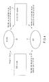
- FIGS. 1 and 2 are explanatory views showing examples of a relationship between an optical disk apparatus of the embodiment and another optical disk apparatus.
- FIG. 3 is an explanatory view showing an example of a directory file generated by the optical disk apparatus of the embodiment.
- FIG. 4 is also an explanatory view showing an example of the relationship between the optical disk apparatus of the embodiment and another optical disk apparatus.
- the information recording and reproduction apparatus 2 of the embodiment is characterized in that, when contents are recorded in a first format with the information recording and reproduction apparatus 2 which can perform recording and reproduction onto a medium D in plural first and second formats, the warning information in the second format is recorded in the medium D in order that the information recording and reproduction apparatus 1 does not mistakenly delete the contents in the first format.
- the information recording and reproduction apparatus 2 of the embodiment is characterized in that, when contents are recorded in the first format with the information recording and reproduction apparatus 2 which can perform recording and reproduction onto the medium D in the plural first and second formats, the recording of the contents is prohibited in the first format, in the case where contents in the first format do not exist on the medium D, contents in the second format exist on the medium D, and the warning information in the second format does not exist on the medium D.
- the information recording and reproduction apparatus 2 of the embodiment which can perform recording and reproduction onto the medium D in the plural first and second formats, uses a format of the same file system when recording contents in the first format and contents in the second format. Therefore, contents in the plural formats can be recorded in and reproduced from the same media D and D2.
- the information recording and reproduction apparatuses 1' and 2' of the embodiment are a DVD-VR recorder 1' and an HD DVD-VR recorder 2', respectively.
- the DVD-VR recorder 1' can access only the optical disk D which is DVD, while the HD DVD-VR recorder 2' can perform the recording and reproduction processes to both the optical disk D which is DVD and the optical disk D2 which is HD DVD.
- the information recording and reproduction apparatus 2 of the embodiment records the warning information in the second format in the optical disk D which is a legacy DVD.
- FIG. 5 is a block diagram showing an example of a configuration of an optical disk apparatus.
- the optical disk apparatus 1' of the embodiment includes the optical disk D, a control unit 3 which controls the whole operation, a buffer 5 in which a data stream read from the optical disk D is stored, an LDD 6 which controls a laser beam of an optical pickup, a PUH actuator 8 which controls an optical pickup head and a position of the optical pickup head, and a PD 10 which receives light of a detection signal detected from the optical pickup head and outputs the detection signal.
- the optical disk apparatus 1' also includes a preamplifier 12 which appropriately amplifies the detected signal, a DVD-VR processing unit 14 which decodes DVD-VR content information, a reproduction circuit 15 which processes a video signal and a sound signal which are the decoded read signal, a servo circuit 18 which controls a spindle motor 20 to a proper speed, the spindle motor 20, a detachable memory 21 in which the data stream is stored, and a communication unit 22 which obtains the data stream through a network such as the Internet.
- a preamplifier 12 which appropriately amplifies the detected signal
- a DVD-VR processing unit 14 which decodes DVD-VR content information
- a reproduction circuit 15 which processes a video signal and a sound signal which are the decoded read signal
- a servo circuit 18 which controls a spindle motor 20 to a proper speed, the spindle motor 20, a detachable memory 21 in which the data stream is stored
- a communication unit 22 which obtains the data stream through
- the laser beam emitted from the PUH (Optical Pick-Up Head) actuator 8 is focused on an information recording layer in the optical disk D rotated by the spindle motor 20 (laser beam is focused on a target recording layer by focus servo), thereby recording and reproducing the information.
- the light reflected from the optical disk D passes through an optical system of the PUH actuator 8 again, and the light is detected as an electric signal by the PD (photodetector) 10.
- the preamplifier 12 amplifies the detected electric signal, and outputs the amplified electric signal to the servo circuit 18 and the DVD-VR processing unit 14.
- the servo circuit 18 generates servo signals such as a focus signal, a tracking signal, a tilt signal, and a rotating speed signal, and outputs the servo signals to focus, tracking, and tilt actuators (not shown) in the PUH actuator 8.
- the servo circuit 18 transmits the rotating speed servo signal to a driving circuit system of the spindle motor 20 to control a linear velocity of a laser beam spot to a predetermined value on the recording layer of the optical disk.
- the control unit 3 reads data (user data) of a desired address position and records data in a desired address position based on address information.
- a recording waveform circuit (not shown) in the LDD (Laser Diode Driving Circuit) 6 modulates the recording data into a recording waveform control signal suitable to the optical disk recording. Based on the modulated signal, the LDD 6 causes the laser diode to emit the light to record information in the optical disk D.
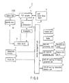
- FIG. 6 is a block diagram showing an example of a configuration of the optical disk apparatus of the embodiment.
- the optical disk apparatus 2' of the embodiment includes the optical disk D, the control unit 3 which controls the whole operation, the buffer 5 in which the data stream read from the optical disk D is stored, the LDD 6 which controls the laser beam of the optical pickup, the PUH actuator 8 which controls the optical pickup head and the position of the optical pickup head, and the PD 10 which receives the light of the detection signal detected from the optical pickup head and outputs the detection signal.
- the optical disk apparatus 2' of the embodiment also includes the preamplifier 12 which appropriately amplifies the detected signal, the DVD-VR processing unit 14 which decodes DVD-VR content information, the reproduction circuit 15 which processes the video signal and sound signal which are the decoded read signal, an HD DVD-VR processing circuit 16 which decodes HD DVD-VR content information by an AACS (Advanced Access Content System) processing, a reproduction circuit 17 which processes the video signal and sound signal which are the decoded read signal, the servo circuit 18 which controls the spindle motor 20 to a proper speed, the spindle motor 20, the detachable memory 21 in which the data stream is stored, and the communication unit 22 which obtains the data stream through the network such as the Internet.
- the preamplifier 12 which appropriately amplifies the detected signal
- the DVD-VR processing unit 14 which decodes DVD-VR content information
- the reproduction circuit 15 which processes the video signal and sound signal which are the decoded read signal
- an HD DVD-VR processing circuit 16 which decodes HD DVD-VR content information
- the optical disk apparatus 2' of the embodiment also includes a DVD-VR warning information generation unit 23 which generates DVD-VR warning information described later and a DVD-VR warning information detection unit 24 which detects the DVD-VR warning information.
- the laser beam emitted from the PUH (Optical Pick-Up Head) actuator 8 is focused on the information recording layer in the optical disk D rotated by the spindle motor 20 (laser beam is focused on the target recording layer by the focus servo), thereby recording and reproducing the information.
- the light reflected from the optical disk D passes through the optical system of the PUH actuator 8 again, and the light is detected as the electric signal by the PD (photodetector) 10.
- the preamplifier 12 amplifies the detected electric signal, and outputs the amplified electric signal to the servo circuit 18 and the DVD-VR processing unit 14.
- the servo circuit 18 generates the servo signals such as the focus signal, the tracking signal, the tilt signal, and the rotating speed signal, and outputs the servo signals to the focus, tracking, and tilt actuators (not shown) in the PUH actuator 8.
- the servo circuit 18 transmits the rotating speed servo signal to the driving circuit system of the spindle motor 20 to control the linear velocity of the laser beam spot to a predetermined value on the recording layer of the optical disk.
- the control unit 3 reads data (user data) of a desired address position and records data in a desired address position based on address information.
- the recording waveform circuit (not shown) in the LDD (Laser Diode Driving Circuit) 6 modulates the recording data into the recording waveform control signal suitable to the optical disk recording. Based on the modulated signal, the LDD 6 causes the laser diode to emit the light to record information in the optical disk D.
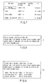
- FIG. 7 is an explanatory view showing an example of a content list shown by the optical disk apparatus of the embodiment.
- FIGS. 8 and 9 are explanatory views showing examples of a warning screen generated by the optical disk apparatus of the embodiment.
- FIGS. 10 to 12 are flowcharts showing examples of a warning title generating process performed by the optical disk apparatus of the embodiment.
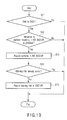
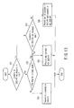
- FIG. 13 is a flowchart showing an example of a recording process performed by the optical disk apparatus of the embodiment.
- the optical disk apparatus 2' of the embodiment records the warning information such as a warning title according to the following procedure.
- the optical disk apparatus 2' is an HD DVD-VR recorder which can record and reproduce the optical disk in HD DVD-VR and DVD-VR, and can perform the recording in the HD DVD-VR format and DVD-VR format to the legacy DVD.
- the control unit 3 and the DVD-VR warning information generation unit 23 determine whether or not the recording target optical disk is the legacy DVD (Step S11).
- the control unit 3 and the DVD-VR warning information generation unit 23 determine that the recording target optical disk is the legacy DVD
- the control unit 3 and the DVD-VR warning information generation unit 23 determine whether or not an instruction to perform the recording in the HD DVD-VR format is provided (Step S12).
- the instruction to perform the recording in the HD DVD-VR format contents are recorded in the HD DVD-VR format in the optical disk D2 (Step S13).
- control unit 3 and the DVD-VR warning information detection unit 24 determine whether or not the warning information such as the warning title is already recorded in the recording target optical disk (Step S14).
- control unit 3 and the DVD-VR warning information detection unit 24 determine that the warning information such as the warning title is not recorded in the recording target optical disk
- the control unit 3 and the DVD-VR warning information generation unit 23 generate the warning information such as the warning title to record the warning information in the target optical disk (Step S15).
- FIG. 7 shows an example of the warning information such as the warning title.
- a warning title K can be displayed by the DVD-VR recorder 1' which can reproduce only contents in the DVD-VR format.
- a user can understand that contents in the HD DVD-VR format are recorded in the legacy DVD by the warning title K, although the user cannot usually recognize that contents in the HD DVD-VR format are recorded in the legacy DVD. Therefore, the warning information prevents the wrong format from deleting the contents in the HD DVD-VR format.
- the warning information has effect only by the warning title K as shown in FIG. 7 .
- a warning screen R such as "Data is recorded in first format (such as HD DVD-VR) in this disk.
- first format such as HD DVD-VR
- second format such as DVD-VR
- FIG. 8 a warning screen R
- the warning screen R is displayed as shown in FIG. 8 , which allows the user to know the existence of the contents in the HD DVD-VR format which cannot usually be recognized in the screen.
- Step S21 of a flowchart of FIG. 11 the control unit 3 and the DVD-VR warning information generation unit 23 preferably record the warning title K in a leading position on a title list of the optical disk D2 such that the user does not overlook the warning title K.
- Step S22 of a flowchart of FIG. 12 the control unit 3 and the DVD-VR warning information generation unit 23 preferably record the warning information in the DVD-VR format indicating the whole HD DVD-VR content list.
- the pieces of information such as the content title name, the recording date and time, and the time which are currently recorded in the HD DVD-VR format in the legacy DVD are simultaneously displayed as shown by a warning screen R2 of FIG. 9 . Therefore, the user can know the specific contents in the HD DVD-VR format.
- Step S14 it is necessary for the control unit 3 and the DVD-VR warning information generation unit 23 to perform the recording by replacing the HD DVD-VR content list with the already-existing warning contents in the DVD-VR format after updating the HD DVD-VR content list (Step S23).
- the optical disk apparatus 2' of the embodiment preferably restrictions are imposed on the recording format such that many recording formats are not diffused.
- the control unit 3 determines whether or not contents in the DVD-VR format are recorded in the optical disk (Step S31). When the control unit 3 determines that the contents in the DVD-VR format are recorded in the optical disk, the control unit 3 determines whether or not the warning title already exists in the optical disk (Step S32). When the control unit 3 determines that the warning title does not exist in the optical disk, the flow goes to Step S34 to preferably record only the contents in the DVD-VR format.
- Step S32 When the control unit 3 determines that the warning title already exists in Step S32, the flow goes to Step S35 to preferably record only the contents in the HD DVD-VR format.
- Step S31 When the control unit 3 determines that the contents in the DVD-VR format are not recorded in the optical disk in Step S31, the flow goes to Step S33, and the control unit 3 determines whether or not contents in the HD DVD-VR format are recorded in the optical disk. When the control unit 3 determines that the contents in the HD DVD-VR format are recorded in the optical disk, the flow goes to Step S35 to preferably record only the contents in the HD DVD-VR format.
- Step S33 When the control unit 3 determines in Step S33 that the contents in the HD DVD-VR format are not recorded in the optical disk, the flow goes to Step S36 to preferably record one of the contents in the HD DVD-VR format and the contents in the DVD-VR format.
- control unit 3 recognizes how the warning information and contents in each format are recorded in the optical disk, and the restrictions are imposed on the recording in each format, so that the recording can be performed without diffusing the many recording formats.
- the DVD-VR format and the HD DVD-VR format are described in the recording and reproduction apparatus.
- the invention is not limited to the DVD-VR format and the HD DVD-VR format, but obviously the similar warning information can be generated in other application formats to obtain the same advantage.
Landscapes
- Management Or Editing Of Information On Record Carriers (AREA)
- Optical Recording Or Reproduction (AREA)
- Signal Processing For Digital Recording And Reproducing (AREA)
Abstract
According to one embodiment, there is provided an optical disk apparatus including a recording unit (8, 6) which irradiates an optical disk (D) with a laser beam to record information in a first format and a second format, a generation unit (23) which generates warning information to an optical disk apparatus capable of performing a read process in the second format while being not capable of performing the read process in the first format, the warning information warning that information is recorded in the first format in the optical disk (D), and a control unit (3) which controls the recording unit to record the warning information in the second format in the optical disk (D) when the information is recorded in the first format in the optical disk (D).
Description
- One embodiment of the invention relates to an optical disk apparatus in which warning information is recorded in a second format when recording is performed in a first format and an optical disk recording method.
- Recently, with widespread use of a digital video technology, sometimes plural formats are used for one medium. However, confusion is possibly promoted because the recording and reproduction are performed in the plural formats. Therefore, there is known a technique for a countermeasure against the promotion of the confusion.
- Jpn. Pat. Appln. KOKAI Publication No.
2003-346428 - However, in the technique disclosed in Jpn. Pat. Appln. KOKAI Publication No.
2003-346428 - An object of the invention is to provide an optical disk apparatus in which application data is not carelessly deleted by an irreproducible reproduction apparatus when the application data is recorded and an optical disk recording method.
- One embodiment for achieving the object is an optical disk apparatus comprising:
- a recording unit which irradiates an optical disk with a laser beam to record information in a first format and a second format;
- a generation unit which generates warning information to an optical disk apparatus capable of performing a read process in the second format while being not capable of performing the read process in the first format, the warning information warning that information is recorded in the first format in the optical disk; and
- a control unit which controls the recording unit to record the warning information generated by the generation unit in the second format in the optical disk apparatus when the information is recorded in the first format in the optical disk.
- When application data is recorded in the medium, in order that a recording apparatus which cannot reproduce the application data does not mistakenly initialize and delete the application data, warning information is recorded in the medium in a format reproducible by the recording apparatus.
- The invention can be more fully understood from the following detailed description when taken in conjunction with the accompanying drawings, in which:
-
FIG. 1 is an explanatory view showing an example of a relationship between an optical disk apparatus according to an embodiment of the invention and another optical disk apparatus; -
FIG. 2 is an explanatory view showing another example of the relationship between the optical disk apparatus of the embodiment and another optical disk apparatus; -
FIG. 3 is an explanatory view showing an example of a directory file generated by the optical disk apparatus of the embodiment; -
FIG. 4 is an explanatory view showing an example of the relationship between the optical disk apparatus of the embodiment and another optical disk apparatus; -
FIG. 5 is a block diagram showing an example of a configuration of another optical disk apparatus; -
FIG. 6 is a block diagram showing an example of a configuration of the optical disk apparatus of the embodiment; -
FIG. 7 is an explanatory view showing an example of a content list shown by the optical disk apparatus of the embodiment; -
FIG. 8 is an explanatory view showing an example of a warning screen generated by the optical disk apparatus of the embodiment; -
FIG. 9 is an explanatory view showing another example of the warning screen generated by the optical disk apparatus of the embodiment; -
FIG. 10 is a flowchart showing an example of a warning title generating process performed by the optical disk apparatus of the embodiment; -
FIG. 11 is a flowchart showing another example of the warning title generating process performed by the optical disk apparatus of the embodiment; -
FIG. 12 is a flowchart showing another example of the warning title generating process performed by the optical disk apparatus of the embodiment; and -
FIG. 13 is a flowchart showing an example of a recording process performed by the optical disk apparatus of the embodiment. - An object of an embodiment of the invention is to provide an optical disk apparatus in which application data is not carelessly deleted by an irreproducible reproduction apparatus when the application data is recorded and an optical disk recording method.
- In order to solve the problem, an optical disk apparatus of the embodiment is characterized by including:
- a recording unit (8, 6) which irradiates an optical disk (D) with a laser beam to record information in a first format (HD DVD-VR) and a second format (DVD-VR);
- a generation unit (23) which generates warning information to an optical disk apparatus capable of performing a read process in the second format while being not capable of performing the read process in the first format, the warning information warning that information is recorded in the first format in the optical disk (D); and
- a control unit (3) which controls the recording unit (8, 6) to record the warning information generated by the generation unit (23) in the second format in the optical disk (D) when the information is recorded in the first format in the optical disk (D).
- Therefore, when application data is recorded in the medium, in order that a recording apparatus which cannot reproduce the application data does not mistakenly initialize and delete the application data, warning information is recorded in the medium in a format reproducible by the recording apparatus.
- An embodiment of the invention will be described in detail with reference to the drawings.
- The embodiment of the invention, as shown below, becomes effective between a one-format compatible information recording and
reproduction apparatus 1 and a plural-format compatible information recording andreproduction apparatus 2.FIGS. 1 and 2 are explanatory views showing examples of a relationship between an optical disk apparatus of the embodiment and another optical disk apparatus.FIG. 3 is an explanatory view showing an example of a directory file generated by the optical disk apparatus of the embodiment.FIG. 4 is also an explanatory view showing an example of the relationship between the optical disk apparatus of the embodiment and another optical disk apparatus. - For example, as shown in
FIG. 1 , the information recording andreproduction apparatus 2 of the embodiment is characterized in that, when contents are recorded in a first format with the information recording andreproduction apparatus 2 which can perform recording and reproduction onto a medium D in plural first and second formats, the warning information in the second format is recorded in the medium D in order that the information recording andreproduction apparatus 1 does not mistakenly delete the contents in the first format. - For example, as shown in
FIG. 2 , the information recording andreproduction apparatus 2 of the embodiment is characterized in that, when contents are recorded in the first format with the information recording andreproduction apparatus 2 which can perform recording and reproduction onto the medium D in the plural first and second formats, the recording of the contents is prohibited in the first format, in the case where contents in the first format do not exist on the medium D, contents in the second format exist on the medium D, and the warning information in the second format does not exist on the medium D. - For example, as shown in
FIG. 3 , the information recording andreproduction apparatus 2 of the embodiment, which can perform recording and reproduction onto the medium D in the plural first and second formats, uses a format of the same file system when recording contents in the first format and contents in the second format. Therefore, contents in the plural formats can be recorded in and reproduced from the same media D and D2. - For example, as shown in
FIG. 4 , the information recording and reproduction apparatuses 1' and 2' of the embodiment are a DVD-VR recorder 1' and an HD DVD-VR recorder 2', respectively. The DVD-VR recorder 1' can access only the optical disk D which is DVD, while the HD DVD-VR recorder 2' can perform the recording and reproduction processes to both the optical disk D which is DVD and the optical disk D2 which is HD DVD. - The information recording and
reproduction apparatus 2 of the embodiment records the warning information in the second format in the optical disk D which is a legacy DVD. - Examples of configurations of the information recording and
reproduction apparatuses FIGS. 5 and6 . -
FIG. 5 is a block diagram showing an example of a configuration of an optical disk apparatus. Referring toFIG. 5 , the optical disk apparatus 1' of the embodiment includes the optical disk D, acontrol unit 3 which controls the whole operation, abuffer 5 in which a data stream read from the optical disk D is stored, anLDD 6 which controls a laser beam of an optical pickup, aPUH actuator 8 which controls an optical pickup head and a position of the optical pickup head, and aPD 10 which receives light of a detection signal detected from the optical pickup head and outputs the detection signal. - As shown in
FIG. 5 , the optical disk apparatus 1' also includes apreamplifier 12 which appropriately amplifies the detected signal, a DVD-VR processing unit 14 which decodes DVD-VR content information, areproduction circuit 15 which processes a video signal and a sound signal which are the decoded read signal, aservo circuit 18 which controls aspindle motor 20 to a proper speed, thespindle motor 20, adetachable memory 21 in which the data stream is stored, and acommunication unit 22 which obtains the data stream through a network such as the Internet. - In the
optical disk apparatus 1, the laser beam emitted from the PUH (Optical Pick-Up Head)actuator 8 is focused on an information recording layer in the optical disk D rotated by the spindle motor 20 (laser beam is focused on a target recording layer by focus servo), thereby recording and reproducing the information. The light reflected from the optical disk D passes through an optical system of thePUH actuator 8 again, and the light is detected as an electric signal by the PD (photodetector) 10. - The
preamplifier 12 amplifies the detected electric signal, and outputs the amplified electric signal to theservo circuit 18 and the DVD-VR processing unit 14. Theservo circuit 18 generates servo signals such as a focus signal, a tracking signal, a tilt signal, and a rotating speed signal, and outputs the servo signals to focus, tracking, and tilt actuators (not shown) in thePUH actuator 8. Theservo circuit 18 transmits the rotating speed servo signal to a driving circuit system of thespindle motor 20 to control a linear velocity of a laser beam spot to a predetermined value on the recording layer of the optical disk. - The
control unit 3 reads data (user data) of a desired address position and records data in a desired address position based on address information. At this point, a recording waveform circuit (not shown) in the LDD (Laser Diode Driving Circuit) 6 modulates the recording data into a recording waveform control signal suitable to the optical disk recording. Based on the modulated signal, theLDD 6 causes the laser diode to emit the light to record information in the optical disk D. - Next, a configuration and an operation of a plural-format compatible optical disk apparatus will be described.
FIG. 6 is a block diagram showing an example of a configuration of the optical disk apparatus of the embodiment. - As shown in
FIG. 6 , the optical disk apparatus 2' of the embodiment includes the optical disk D, thecontrol unit 3 which controls the whole operation, thebuffer 5 in which the data stream read from the optical disk D is stored, theLDD 6 which controls the laser beam of the optical pickup, thePUH actuator 8 which controls the optical pickup head and the position of the optical pickup head, and thePD 10 which receives the light of the detection signal detected from the optical pickup head and outputs the detection signal. - As shown in
FIG. 6 , the optical disk apparatus 2' of the embodiment also includes thepreamplifier 12 which appropriately amplifies the detected signal, the DVD-VR processing unit 14 which decodes DVD-VR content information, thereproduction circuit 15 which processes the video signal and sound signal which are the decoded read signal, an HD DVD-VR processing circuit 16 which decodes HD DVD-VR content information by an AACS (Advanced Access Content System) processing, areproduction circuit 17 which processes the video signal and sound signal which are the decoded read signal, theservo circuit 18 which controls thespindle motor 20 to a proper speed, thespindle motor 20, thedetachable memory 21 in which the data stream is stored, and thecommunication unit 22 which obtains the data stream through the network such as the Internet. - As shown in
FIG. 6 , the optical disk apparatus 2' of the embodiment also includes a DVD-VR warninginformation generation unit 23 which generates DVD-VR warning information described later and a DVD-VR warning information detection unit 24 which detects the DVD-VR warning information. - In the optical disk apparatus 2' of the embodiment, the laser beam emitted from the PUH (Optical Pick-Up Head)
actuator 8 is focused on the information recording layer in the optical disk D rotated by the spindle motor 20 (laser beam is focused on the target recording layer by the focus servo), thereby recording and reproducing the information. The light reflected from the optical disk D passes through the optical system of thePUH actuator 8 again, and the light is detected as the electric signal by the PD (photodetector) 10. - The
preamplifier 12 amplifies the detected electric signal, and outputs the amplified electric signal to theservo circuit 18 and the DVD-VR processing unit 14. Theservo circuit 18 generates the servo signals such as the focus signal, the tracking signal, the tilt signal, and the rotating speed signal, and outputs the servo signals to the focus, tracking, and tilt actuators (not shown) in thePUH actuator 8. Theservo circuit 18 transmits the rotating speed servo signal to the driving circuit system of thespindle motor 20 to control the linear velocity of the laser beam spot to a predetermined value on the recording layer of the optical disk. - The
control unit 3 reads data (user data) of a desired address position and records data in a desired address position based on address information. At this point, the recording waveform circuit (not shown) in the LDD (Laser Diode Driving Circuit) 6 modulates the recording data into the recording waveform control signal suitable to the optical disk recording. Based on the modulated signal, theLDD 6 causes the laser diode to emit the light to record information in the optical disk D. - An example of a warning process performed by the optical disk apparatus 2' of the embodiment will be described with reference to a flowchart.
FIG. 7 is an explanatory view showing an example of a content list shown by the optical disk apparatus of the embodiment.FIGS. 8 and 9 are explanatory views showing examples of a warning screen generated by the optical disk apparatus of the embodiment. -
FIGS. 10 to 12 are flowcharts showing examples of a warning title generating process performed by the optical disk apparatus of the embodiment.FIG. 13 is a flowchart showing an example of a recording process performed by the optical disk apparatus of the embodiment. - Each step of the flowcharts shown in
FIGS. 10 to 13 can be replaced by a circuit block, and therefore all steps of each flowchart can be redefined as blocks. - The optical disk apparatus 2' of the embodiment records the warning information such as a warning title according to the following procedure. For example, the optical disk apparatus 2' is an HD DVD-VR recorder which can record and reproduce the optical disk in HD DVD-VR and DVD-VR, and can perform the recording in the HD DVD-VR format and DVD-VR format to the legacy DVD.
- As shown in the flowchart of
FIG. 10 , when the optical disk apparatus 2' receives a recording instruction, thecontrol unit 3 and the DVD-VR warninginformation generation unit 23 determine whether or not the recording target optical disk is the legacy DVD (Step S11). When thecontrol unit 3 and the DVD-VR warninginformation generation unit 23 determine that the recording target optical disk is the legacy DVD, thecontrol unit 3 and the DVD-VR warninginformation generation unit 23 determine whether or not an instruction to perform the recording in the HD DVD-VR format is provided (Step S12). When the instruction to perform the recording in the HD DVD-VR format is provided, contents are recorded in the HD DVD-VR format in the optical disk D2 (Step S13). Then, thecontrol unit 3 and the DVD-VR warning information detection unit 24 determine whether or not the warning information such as the warning title is already recorded in the recording target optical disk (Step S14). When thecontrol unit 3 and the DVD-VR warning information detection unit 24 determine that the warning information such as the warning title is not recorded in the recording target optical disk, thecontrol unit 3 and the DVD-VR warninginformation generation unit 23 generate the warning information such as the warning title to record the warning information in the target optical disk (Step S15). -
FIG. 7 shows an example of the warning information such as the warning title. For example, a warning title K can be displayed by the DVD-VR recorder 1' which can reproduce only contents in the DVD-VR format. A user can understand that contents in the HD DVD-VR format are recorded in the legacy DVD by the warning title K, although the user cannot usually recognize that contents in the HD DVD-VR format are recorded in the legacy DVD. Therefore, the warning information prevents the wrong format from deleting the contents in the HD DVD-VR format. - The warning information has effect only by the warning title K as shown in
FIG. 7 . Additionally, a warning screen R such as "Data is recorded in first format (such as HD DVD-VR) in this disk. Although data is not displayed on second format (such as DVD-VR) compatible player, perform deletion or initialization after contents are confirmed with first format compatible player." is preferably provided as shown inFIG. 8 . That is, when the user specifies the warning title K to perform the reproduction, the warning screen R is displayed as shown inFIG. 8 , which allows the user to know the existence of the contents in the HD DVD-VR format which cannot usually be recognized in the screen. - Furthermore, in Step S21 of a flowchart of
FIG. 11 , thecontrol unit 3 and the DVD-VR warninginformation generation unit 23 preferably record the warning title K in a leading position on a title list of the optical disk D2 such that the user does not overlook the warning title K. - Furthermore, in Step S22 of a flowchart of
FIG. 12 , thecontrol unit 3 and the DVD-VR warninginformation generation unit 23 preferably record the warning information in the DVD-VR format indicating the whole HD DVD-VR content list. Preferably the pieces of information such as the content title name, the recording date and time, and the time which are currently recorded in the HD DVD-VR format in the legacy DVD are simultaneously displayed as shown by a warning screen R2 ofFIG. 9 . Therefore, the user can know the specific contents in the HD DVD-VR format. - In the case where the warning information is included in the HD DVD-VR content list, when the warning information already exists (Step S14), it is necessary for the
control unit 3 and the DVD-VR warninginformation generation unit 23 to perform the recording by replacing the HD DVD-VR content list with the already-existing warning contents in the DVD-VR format after updating the HD DVD-VR content list (Step S23). - In the optical disk apparatus 2' of the embodiment, preferably restrictions are imposed on the recording format such that many recording formats are not diffused.
- In the optical disk apparatus 2', as shown in a flowchart of
FIG. 13 , thecontrol unit 3 determines whether or not contents in the DVD-VR format are recorded in the optical disk (Step S31). When thecontrol unit 3 determines that the contents in the DVD-VR format are recorded in the optical disk, thecontrol unit 3 determines whether or not the warning title already exists in the optical disk (Step S32). When thecontrol unit 3 determines that the warning title does not exist in the optical disk, the flow goes to Step S34 to preferably record only the contents in the DVD-VR format. - When the
control unit 3 determines that the warning title already exists in Step S32, the flow goes to Step S35 to preferably record only the contents in the HD DVD-VR format. - When the
control unit 3 determines that the contents in the DVD-VR format are not recorded in the optical disk in Step S31, the flow goes to Step S33, and thecontrol unit 3 determines whether or not contents in the HD DVD-VR format are recorded in the optical disk. When thecontrol unit 3 determines that the contents in the HD DVD-VR format are recorded in the optical disk, the flow goes to Step S35 to preferably record only the contents in the HD DVD-VR format. - When the
control unit 3 determines in Step S33 that the contents in the HD DVD-VR format are not recorded in the optical disk, the flow goes to Step S36 to preferably record one of the contents in the HD DVD-VR format and the contents in the DVD-VR format. - Thus, the
control unit 3 recognizes how the warning information and contents in each format are recorded in the optical disk, and the restrictions are imposed on the recording in each format, so that the recording can be performed without diffusing the many recording formats. - Although those skilled in the art can realize the invention by various embodiments described above, those skilled in the art can easily make various modifications of the embodiments and applies the invention to various embodiments without inventive ability. Accordingly, the invention is not limited to the embodiments, but the invention covers a wide range which is consistent with the disclosed principles and novel features.
- For example, in the embodiments, the DVD-VR format and the HD DVD-VR format are described in the recording and reproduction apparatus. However, the invention is not limited to the DVD-VR format and the HD DVD-VR format, but obviously the similar warning information can be generated in other application formats to obtain the same advantage.
Claims (10)
- An optical disk apparatus characterized by comprising:a recording unit (8, 6) which irradiates an optical disk (D) with a laser beam to record information in a first format (HD DVD-VR) and a second format (DVD-VR);a generation unit (23) which generates warning information to an optical disk apparatus capable of performing a read process in the second format while being not capable of performing the read process in the first format, the warning information warning that information is recorded in the first format in the optical disk (D); anda control unit (3) which controls the recording unit (8, 6) to record the warning information generated by the generation unit (23) in the second format in the optical disk (D) when the information is recorded in the first format in the optical disk (D).
- The optical disk apparatus according to claim 1, characterized in that, in the warning information generated by the generation unit, information indicating a warning is included in title information.
- The optical disk apparatus according to claim 1, characterized in that the first format is an HD DVD-VR format and the second format is a DVD-VR format.
- The optical disk apparatus according to claim 3, characterized in that the control unit prohibits recording in the HD DVD-VR format when contents are recorded in the DVD-VR format in the optical disk (D) while the warning information is not recorded.
- The optical disk apparatus according to claim 3, characterized in that the control unit performs only recording in the HD DVD-VR format when contents are recorded in the DVD-VR format in the optical disk (D) while the warning information is recorded.
- The optical disk apparatus according to claim 1, characterized in that the control unit records contents in the first format in a file system standard recognizable by an apparatus reproducing contents in the second format.
- The optical disk apparatus according to claim 1, characterized in that the warning information includes a warning message in contents in the second format.
- The optical disk apparatus according to claim 1, characterized in that the warning information includes a warning message and title information on contents recorded in the first format in contents in the second format.
- The optical disk apparatus according to claim 1, characterized in that the control unit updates the warning information by adding title information on new contents to the warning information when the new contents are recorded in the first format.
- An optical disk recording method characterized by comprising:recording information in a first format (HD DVD-VR) in an optical disk (D); andrecording warning information in a second format (DVD-VR) in the optical disk (D), the second format being different from the first format, the warning information being given to an optical disk apparatus capable of performing a read process in the second format while being not capable of performing the read process in the first format, the warning information warning that information is recorded in the first format in the optical disk (D).
Applications Claiming Priority (1)
| Application Number | Priority Date | Filing Date | Title |
|---|---|---|---|
| JP2007169426A JP2009009637A (en) | 2007-06-27 | 2007-06-27 | Optical disc apparatus and optical disc recording method |
Publications (1)
| Publication Number | Publication Date |
|---|---|
| EP2009625A2 true EP2009625A2 (en) | 2008-12-31 |
Family
ID=39856348
Family Applications (1)
| Application Number | Title | Priority Date | Filing Date |
|---|---|---|---|
| EP08156000A Withdrawn EP2009625A2 (en) | 2007-06-27 | 2008-05-09 | Optical disk apparatus and optical disc recording method |
Country Status (4)
| Country | Link |
|---|---|
| US (1) | US7940619B2 (en) |
| EP (1) | EP2009625A2 (en) |
| JP (1) | JP2009009637A (en) |
| CN (1) | CN101335038A (en) |
Families Citing this family (1)
| Publication number | Priority date | Publication date | Assignee | Title |
|---|---|---|---|---|
| WO2015005683A1 (en) * | 2013-07-09 | 2015-01-15 | 삼성전자주식회사 | Image processing apparatus, image processing method, and optical disk |
Citations (1)
| Publication number | Priority date | Publication date | Assignee | Title |
|---|---|---|---|---|
| JP2003346428A (en) | 2002-03-18 | 2003-12-05 | Sanyo Electric Co Ltd | Optical disk drive |
Family Cites Families (8)
| Publication number | Priority date | Publication date | Assignee | Title |
|---|---|---|---|---|
| JPH11149643A (en) * | 1997-11-18 | 1999-06-02 | Sanyo Electric Co Ltd | Optical record medium |
| JP4211166B2 (en) * | 1999-12-10 | 2009-01-21 | ソニー株式会社 | Encoding apparatus and method, recording medium, and decoding apparatus and method |
| US7149164B2 (en) | 2002-03-18 | 2006-12-12 | Sanyo Electric Co., Ltd. | Optical disc apparatus for processing data according to different optical disc standards to achieve higher recording density |
| AU2003201837A1 (en) * | 2002-04-01 | 2003-10-23 | Sony Corporation | Storage medium and storage medium recording method |
| JP3668213B2 (en) * | 2002-08-13 | 2005-07-06 | 株式会社東芝 | Optical disc and optical disc apparatus for recording HD content and SD content |
| JP2005190639A (en) * | 2003-12-26 | 2005-07-14 | Toshiba Corp | Information recording / reproducing apparatus and information recording / reproducing method |
| JP2007059011A (en) * | 2005-08-26 | 2007-03-08 | Hitachi Ltd | Data recording method, recording medium, reproducing apparatus and recording / reproducing apparatus |
| US20070047411A1 (en) * | 2005-08-30 | 2007-03-01 | Manuel Rivera | Method and system for verifying media compliance |
-
2007
- 2007-06-27 JP JP2007169426A patent/JP2009009637A/en active Pending
-
2008
- 2008-05-09 EP EP08156000A patent/EP2009625A2/en not_active Withdrawn
- 2008-05-23 CN CNA2008101090599A patent/CN101335038A/en active Pending
- 2008-05-29 US US12/129,589 patent/US7940619B2/en not_active Expired - Fee Related
Patent Citations (1)
| Publication number | Priority date | Publication date | Assignee | Title |
|---|---|---|---|---|
| JP2003346428A (en) | 2002-03-18 | 2003-12-05 | Sanyo Electric Co Ltd | Optical disk drive |
Also Published As
| Publication number | Publication date |
|---|---|
| JP2009009637A (en) | 2009-01-15 |
| CN101335038A (en) | 2008-12-31 |
| US20090003159A1 (en) | 2009-01-01 |
| US7940619B2 (en) | 2011-05-10 |
Similar Documents
| Publication | Publication Date | Title |
|---|---|---|
| US7180841B2 (en) | Recording method, recording medium, program, information recording medium, and information recording device | |
| RU2000130875A (en) | OPTICAL DISC AND DEVICE FOR OPTICAL DISK | |
| JP4629032B2 (en) | Information recording medium and recording and / or reproducing method thereof | |
| US7940619B2 (en) | Optical disk apparatus and optical disk recording method with format warning information | |
| US8472290B2 (en) | Apparatus and method identifying disc type | |
| JPH07226012A (en) | Optical disk and device for reproducing optical disk | |
| JP2007509450A (en) | Apparatus and method for recording information | |
| US20070025199A1 (en) | Recorder, recording method and recording medium where program is recorded | |
| JP4175356B2 (en) | Optical disk recording device | |
| KR100298980B1 (en) | Method for regenerating common av file in digital video disk player | |
| EP1209679A2 (en) | Recording apparatus and method for optical recording medium | |
| JP2003242650A (en) | CD-R / RW disk, CD-R / RW drive device and program | |
| JP2008301204A (en) | Playback apparatus and playback method | |
| JP2005182959A (en) | Playback device | |
| KR100632585B1 (en) | Method and device for managing time information about recorded program | |
| JP2003141741A (en) | Information recording and reproduction apparatus for optical disk | |
| JP2000011476A (en) | Optical recording medium | |
| KR100636171B1 (en) | Recording / playback control method in host device, host device, recording / playback method and recording / playback device | |
| US20050058039A1 (en) | Multi-standard optical disk and method and apparatus of reading from and recording to the disk | |
| KR20050011887A (en) | Method for managing and reproducing a presentation graphic data of high density optical disc, and high density optical disc therof | |
| JP3789673B2 (en) | Optical disc recording / reproducing apparatus | |
| JPH07161125A (en) | Optical recording / reproducing apparatus and optical recording medium | |
| KR20030004570A (en) | Method for writing supplement data in an optical disc | |
| JPH10336558A (en) | Editing device | |
| JP2005513700A (en) | System and method for playing a DVD bit stream from a non-DVD optical storage medium |
Legal Events
| Date | Code | Title | Description |
|---|---|---|---|
| PUAI | Public reference made under article 153(3) epc to a published international application that has entered the european phase |
Free format text: ORIGINAL CODE: 0009012 |
|
| 17P | Request for examination filed |
Effective date: 20080509 |
|
| AK | Designated contracting states |
Kind code of ref document: A2 Designated state(s): AT BE BG CH CY CZ DE DK EE ES FI FR GB GR HR HU IE IS IT LI LT LU LV MC MT NL NO PL PT RO SE SI SK TR |
|
| AX | Request for extension of the european patent |
Extension state: AL BA MK RS |
|
| STAA | Information on the status of an ep patent application or granted ep patent |
Free format text: STATUS: THE APPLICATION HAS BEEN WITHDRAWN |
|
| 18W | Application withdrawn |
Effective date: 20090306 |