EP2009396A2 - Low power inertial navigation processing - Google Patents
Low power inertial navigation processing Download PDFInfo
- Publication number
- EP2009396A2 EP2009396A2 EP08158869A EP08158869A EP2009396A2 EP 2009396 A2 EP2009396 A2 EP 2009396A2 EP 08158869 A EP08158869 A EP 08158869A EP 08158869 A EP08158869 A EP 08158869A EP 2009396 A2 EP2009396 A2 EP 2009396A2
- Authority
- EP
- European Patent Office
- Prior art keywords
- navigation
- data
- processing unit
- data buffer
- sensors
- Prior art date
- Legal status (The legal status is an assumption and is not a legal conclusion. Google has not performed a legal analysis and makes no representation as to the accuracy of the status listed.)
- Withdrawn
Links
- 238000012545 processing Methods 0.000 title claims abstract description 118
- 238000005259 measurement Methods 0.000 claims abstract description 59
- 238000000034 method Methods 0.000 claims abstract description 28
- 230000008569 process Effects 0.000 claims abstract description 9
- 238000004891 communication Methods 0.000 claims description 10
- 230000033001 locomotion Effects 0.000 claims description 4
- 230000003213 activating effect Effects 0.000 abstract description 3
- 230000004913 activation Effects 0.000 description 6
- 230000003111 delayed effect Effects 0.000 description 6
- 230000001934 delay Effects 0.000 description 4
- 238000010586 diagram Methods 0.000 description 4
- 238000013459 approach Methods 0.000 description 3
- 238000009499 grossing Methods 0.000 description 3
- 230000000737 periodic effect Effects 0.000 description 3
- 238000009825 accumulation Methods 0.000 description 2
- 230000005540 biological transmission Effects 0.000 description 2
- 238000012937 correction Methods 0.000 description 2
- 238000001914 filtration Methods 0.000 description 2
- 238000012544 monitoring process Methods 0.000 description 2
- 238000012805 post-processing Methods 0.000 description 2
- 230000001133 acceleration Effects 0.000 description 1
- 230000006978 adaptation Effects 0.000 description 1
- 230000009849 deactivation Effects 0.000 description 1
- 230000000694 effects Effects 0.000 description 1
- 230000006870 function Effects 0.000 description 1
- 238000012986 modification Methods 0.000 description 1
- 230000004048 modification Effects 0.000 description 1
- 238000003672 processing method Methods 0.000 description 1
- 230000009467 reduction Effects 0.000 description 1
- 238000013519 translation Methods 0.000 description 1
Images

Classifications
-
- G—PHYSICS
- G01—MEASURING; TESTING
- G01C—MEASURING DISTANCES, LEVELS OR BEARINGS; SURVEYING; NAVIGATION; GYROSCOPIC INSTRUMENTS; PHOTOGRAMMETRY OR VIDEOGRAMMETRY
- G01C21/00—Navigation; Navigational instruments not provided for in groups G01C1/00 - G01C19/00
- G01C21/10—Navigation; Navigational instruments not provided for in groups G01C1/00 - G01C19/00 by using measurements of speed or acceleration
- G01C21/12—Navigation; Navigational instruments not provided for in groups G01C1/00 - G01C19/00 by using measurements of speed or acceleration executed aboard the object being navigated; Dead reckoning
- G01C21/16—Navigation; Navigational instruments not provided for in groups G01C1/00 - G01C19/00 by using measurements of speed or acceleration executed aboard the object being navigated; Dead reckoning by integrating acceleration or speed, i.e. inertial navigation
- G01C21/183—Compensation of inertial measurements, e.g. for temperature effects
- G01C21/188—Compensation of inertial measurements, e.g. for temperature effects for accumulated errors, e.g. by coupling inertial systems with absolute positioning systems
Definitions
- INS inertial navigation systems
- GPS global positioning system
- This real time navigation measurement processing often includes a Kalman filter to improve the overall navigation solution accuracy from a plurality of navigational sensors. Due to processing throughput constraints in a real time implementation with low latency (for example, an output latency less than 100 milliseconds), the Kalman filter uses a periodic "delayed reset" to apply the navigation correction to the navigation solution and sensor error terms. This delayed reset is not an optimal implementation as the resets are applied at least one Kalman period after they were valid. With the delayed reset, the high data rate is continually interrupted in order for a measurement filter to remove unwanted signal noise from the last sensor measurement and compare (that is, resets) the filtered measurement with the next sensor measurement. The delayed comparison results in higher accuracy real time navigation measurements.
- Typical high-data rate navigation applications use a substantial amount of the available data throughput capabilities of the high-speed processing unit.
- the high-speed processing unit continuously executes program instructions to meet various navigation application requirements.
- navigational aids that have less stringent data latency requirements (for example, personal navigation systems) are intended to operate for long periods of time with portable power sources such as a battery power pack.
- the present invention relates to a method and system for processing inertial navigation data.
- the method comprises accumulating measurement data in a data buffer from a plurality of navigational sensors, and activating a processing unit periodically to read and process the accumulated measurement data in the data buffer.
- the processing unit is deactivated once the accumulated measurement data is processed, such that overall power consumption of the processing unit is reduced.
- FIG. 1 is a block diagram of a navigation system
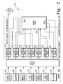
- FIG. 2 is a block diagram showing further details of the navigation system of FIG. 1 ;
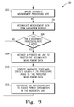
- FIG. 3 is a flow diagram of a method for processing inertial navigation data.
- the present invention relates to a method and system for processing inertial navigation data at low overall power consumption.
- the present method utilizes batch processing of navigation-aiding data, which allows a navigation processing unit to be powered down to a "sleep" mode between batch runs.
- the navigation processing unit is powered down at least 50% of the time, reducing overall power consumption.
- the batch processing described herein allows for additional data processing techniques that increase accuracy and performance for high latency navigation systems (for example, an output latency greater than 100 milliseconds) and similar navigational aids.
- the present method generally comprises accumulating measurement data in a data buffer from a plurality of navigational sensors, and activating a processing unit periodically to read and process the accumulated measurement data in the data buffer. Once the accumulated measurement data is processed, the processing unit is deactivated such that overall power consumption of the processing unit is reduced, such as by a factor of at least two.
- all of the measured navigation sensor data can be time stamped and stored in a low power memory device.
- the navigation processing unit is activated and the sensor data processed to generate a navigation solution. Once the solution is generated, the navigation processing unit is instructed to de-activate until needed again. For example, the navigation processing unit is instructed to end a "sleep" or other power saving mode, process the sensor data, and return to the "sleep" mode to reduce power consumption of the navigation system.
- the present method and system can operate a Kalman filter on accumulated sensor data at substantially the same time as new sensor data is collected.
- a delayed reset approach during real-time data acquisitions involves delaying the filtering of the sensor data on currently-acquired data. Operating the Kalman filter on accumulated data and immediately applying the reset provides more stable measurements than the delayed reset approach is capable of in real-time.
- Further processing techniques include corrections to previous data points by using the Kalman filter for "smoothing" of the measurement data. As the name implies, the data smoothing can correct past navigation results using navigation-aiding measurements from the present time.
- the present processing technique is also an alternative for navigational data measurements with long delays (for example, terrain correlation). Accumulating the data using the batch processing discussed herein eliminates any compensation for long delays and simplifies the navigation processing in navigation systems with low power consumption requirements. Further details of the present invention are discussed hereafter with respect to the Figures.
- FIG. 1 is a navigation system 100.
- the system 100 comprises a navigation processing assembly 102 and a plurality of sensors 104 in communication with the navigation processing assembly 102.
- the navigation processing assembly 102 further includes a navigation processing unit 106 and a data buffer 108 in communication with the navigation processing unit 106.
- each of the sensors 104 is coupled to the data buffer 108.
- the navigation processing unit 106 provides processed navigational data to a system interface 110.
- the data provided to the system interface 110 includes position, velocity, and attitude measurements for at least one of an underwater navigation system, a personal navigation system, or an unmanned ground vehicle (UGV).
- UUV unmanned ground vehicle
- the sensors 104 include one of a micro electro-mechanical system (MEMS) inertial measurement unit, a three-axis magnetometer, a barometric pressure sensor, a selective availability anti-spoofing module (SAASM) GPS receiver, a global navigation satellite system (GNSS) receiver, and the like.
- MEMS micro electro-mechanical system
- SAASM selective availability anti-spoofing module
- GNSS global navigation satellite system
- the navigation processing unit 106 comprises at least one of a microprocessor, a microcontroller, a field-programmable gate array (FPGA), a field-programmable object array (FPOA), a programmable logic device (PLD), or an application-specific integrated circuit (ASIC).
- the data buffer 108 is a memory unit with a first-in, first-out (FIFO) memory configuration (for example, one of a random access memory (RAM) device, an FPGA, a PLD, or an ASIC).
- the data buffer 108 is configured to hold at least 1.5 times the sensor data necessary for a desired navigation output rate of 100 Hz. At an output rate of 1 Hz, the data buffer 108 is configured to hold up to 150 to 200 sensor data measurements.
- the output rate for the navigation processing unit 106 is an adjustable (programmable) output rate.
- the data buffer 108 accumulates navigation measurement data from the plurality of sensors 104.
- the navigation processing unit 106 periodically processes the accumulated measurement data at a first power level (active state) to compute the navigation state (for example, position, velocity, and attitude) of the system 100.
- the periodic processing discussed herein comprises at least one batch processing method which, in one implementation, powers down the navigation processing unit 106 at least 50% of the time to a second power level (inactive state) that is less than the first power level, such that the overall power consumption of the processing unit in the system 100 is reduced by a factor of at least two.
- FIG. 2 shows further details of the navigation system 100 according to one embodiment, which includes the sensors 104, the data buffer 108, and the navigation processing unit 106 of FIG. 1 .
- the sensors 104 can include one or more inertial sensors 204, an altimeter 206, magnetic sensors 208, GNSS sensors 210, electro-optical (EO) sensors 212, light detecting and ranging (LIDAR) sensors 214, a radio-frequency (RF) beacon 216, and various combinations thereof.
- alternate navigational sensors can be implemented (for example, a range finder, an accelerometer, a gyroscope, a stereo vision sensor, or the like).
- the navigation processing unit 106 further comprises a Kalman filter 202 and a plurality of processing blocks 224 to 236 in communication with the Kalman filter 202.
- each of the processing blocks 224 to 236 receive sensor measurement data from the sensors 104 through the data buffer 108.
- the plurality of processing blocks can include one or more of a navigation processing block 224, an altitude processing block 226, a heading computation block 228, a satellite navigation processing block 230, an image processing block 232, a range image processing block 234, an RF range processing block 236, and various combinations thereof.
- the system interface 110 provides (among other functions) power management, interface signal translation (for example, serial to parallel communications), and a monitoring capability for at least a portion of the processing blocks 224 to 236. As shown in FIG. 2 , monitoring capabilities exist between the system interface 110 and the navigation processing block 224, the heading computation block 228, the satellite navigation processing block 230, the image processing block 232, and the range image processing block 234.
- the Kalman filter 202 generates corrective feedback (for example, at least one reset signal) to each of the processing blocks 224 to 236 as shown in FIG. 2 .
- a first reset signal is provided to the navigation processing block 224 to control navigation error growth.
- the navigation processing unit 106 in the example embodiment of FIG. 2 periodically receives an activation signal (command) from the system interface 110.
- an adjustable activation rate is programmed into the navigation processing unit 106, in which a user of the system 100 can refresh (update) the adjustable activation rate.
- the navigation processing unit 106 reads the measurement data from the sensors 104 accumulated in the data buffer 108.
- the processing blocks 224 to 236 process the accumulated measurement data.
- the Kalman filter 202 reads raw accumulated measurement data directly from the data buffer 108 as shown in FIG. 2 .
- activation of the navigation processing unit 106 at the adjustable activation rate eliminates compensating for any prescribed measurement delays as the measurement data is received. For example, to track the accumulated data, the data buffer 108 inserts time stamps for each data message indicating the time of data accumulation.
- the buffered measurement data from the data buffer 108 is processed in the Kalman filter 202 over a filter processing interval.
- the navigation processing unit 106 uses the filtered navigation data from the Kalman filter 202 to further determine a navigational state of the inertial navigation system once the accumulated measurement data is processed.
- the navigational processing unit 106 operates the Kalman filter 202 on the accumulated measurement data while the data buffer 108 continues to collect new measurement data. From the sensor data, the Kalman filter 202 determines the navigational state of the navigation system 100
- the Kalman filter 202 is a measurement filter that removes the effects of signal interference (noise) in the processing blocks 224 to 236.
- the Kalman filter 202 provides an estimate of the location of a target being measured with the sensors 104 at the present time (filtering) or at a time in the past (interpolation or smoothing).
- the Kalman filter 202 receives the buffered sensor measurement data from the processing blocks 224 to 236 (for example, position, velocity, and attitude estimates).
- the post-processing performed in each of the processing blocks 224 to 236 involves applying the Kalman filter 202 to substantially reduce navigation errors.
- the Kalman filter 202 can use a weighted average (or similar approach) to remove erroneous or redundant measurements, resulting in a higher accuracy navigation measurement.
- the post-processing performed by each of the processing blocks 224 to 236 involves applying one or more navigation models based on the real-time recordings gathered by the data buffer 108.
- a distance prediction is estimated by differencing position estimates from the navigation processing block 224 at the stop and start times of the filter processing interval.
- the navigation processing block 224 uses the sensor data received from the inertial sensors 204 to determine the position estimates.
- the inertial sensors 204 comprise a triad of accelerometers and a triad of gyroscopes to provide orthogonal movement and direction signals in at least three dimensions to the navigation processing block 224.
- the navigation processing block 224 processes the signals according to known techniques to provide the position estimate, a velocity estimate, and an attitude estimate to the system interface 110, which can include both direction and heading and the distance moved in that direction.
- the altimeter 206 can include at least one barometric pressure sensor for initial altitude and altitude adjustments of the navigation system 100.
- the altimeter 206 provides pressure sensor data to the altitude processing block 226.
- the navigation system 100 uses the pressure sensor data from the altitude processing block 226 to determine the terrain over which the user is moving. In this case, the altitude processing block 226 measures terrain elevation and the navigation system 100 can predict a terrain correlation position.
- the magnetic sensors 208 can include at least three magnetic sensors mounted orthogonally with respect to one another.
- the magnetic sensors 208 are available for initial heading and as a heading aid for the navigation system 100.
- the magnetic sensors 208 output magnetic sensor data to the heading computation processing block 228.
- the navigation system 100 incorporates navigation information gathered from the GNSS sensors 210, the EO sensors 212, the LIDAR sensors 214, and the RF beacon 216 to obtain accurate geographic location and distance traveled information for the Kalman filter 202.
- the GNSS sensors 210 allow for information to be gathered which accurately tracks the position of the target at any given time.
- the tracking information from the GNSS sensors 210 provides an additional set of values for the distance traveled and position of the target (where the other values for the position and distance traveled were derived from the navigation processing block 224).
- the EO sensors 212 provide images of the target to the image processing block 232.
- the LIDAR sensors 214 can be flash LIDAR sensors that provide range images between the system 100 and the target to the range image processing block 234.
- the RF beacon 216 provides time difference of arrival (TDOA) or time of arrival (TOA) measurements, between the system 100 and the target, to the RF range processing block 236.
- TDOA time difference of arrival
- TOA time of arrival
- FIG. 3 is a flow diagram of a method 300 for processing inertial navigation data using the system shown in FIGS. 1 and 2 .
- An adjustable measurement processing rate is updated (refreshed) (block 302), and measurement data is accumulated from navigational sensors (block 304) in a data buffer. If the adjustable measurement processing rate has not elapsed (block 306), the method returns to block 304. In at least one implementation, the measurement processing rate is configured at a constant rate, and the method continues at block 304. If the measurement processing rate has elapsed (block 306), the processing unit is activated to process the accumulated measurement data (block 308). In one implementation, the data buffer tracks and records the accumulated data with time stamps inserted with the recorded data at the time of accumulation.
- the processing unit retrieves the measurement data as commanded from a navigation system interface to eliminate compensating for prescribed measurement delays.
- movements of the navigation unit are computed based on the processed measurement data (block 310), such as by operating a Kalman filter on the accumulated measurement data at substantially the same time as new measurement data is collected.
- the processing unit is then deactivated to reduce power consumption in the navigation unit (block 312). The method then loops back to block 302 to await another activation sequence.
- machine-readable media include recordable-type media, such as a portable memory device; a hard disk drive (HDD); a random-access memory (RAM); a read-only memory (ROM); transmission-type media, such as digital and analog communications links; and wired or wireless communications links using transmission forms, such as (for example) radio frequency and light wave transmissions.
- program products may take the form of coded formats that are decoded for actual use in a particular inertial navigation system by a combination of digital electronic circuitry or software residing in a programmable processor (for example, a special-purpose processor or a general-purpose processor in a computer).
- a programmable processor for example, a special-purpose processor or a general-purpose processor in a computer.
- At least one embodiment discussed here can be implemented by computer-executable instructions, such as program product modules, which are executed by the programmable processor.
- the program product modules include routines, programs, objects, data components, data structures, and algorithms that perform particular tasks or implement particular abstract data types.
- the computer-executable instructions, the associated data structures, and the program product modules represent examples of executing each of the embodiments disclosed herein.
Landscapes
- Engineering & Computer Science (AREA)
- Radar, Positioning & Navigation (AREA)
- Remote Sensing (AREA)
- Automation & Control Theory (AREA)
- Physics & Mathematics (AREA)
- General Physics & Mathematics (AREA)
- Navigation (AREA)
- Traffic Control Systems (AREA)
Abstract
A method and system for processing inertial navigation data are disclosed. The method comprises accumulating measurement data in a data buffer from a plurality of navigational sensors, and activating a processing unit periodically to read and process the accumulated measurement data in the data buffer. The processing unit is deactivated once the accumulated measurement data is processed, such that overall power consumption of the processing unit is reduced.
Description
- Most navigating applications with inertial navigation systems (INS) include real time processing of navigation measurements such as position, velocity, attitude, or acceleration that are updated at a high data rate (for example, up to 100 updates/second). Typically, these navigation measurements are combined with global positioning system (GPS) location coordinates using high-speed processing units. This real time navigation measurement processing often includes a Kalman filter to improve the overall navigation solution accuracy from a plurality of navigational sensors. Due to processing throughput constraints in a real time implementation with low latency (for example, an output latency less than 100 milliseconds), the Kalman filter uses a periodic "delayed reset" to apply the navigation correction to the navigation solution and sensor error terms. This delayed reset is not an optimal implementation as the resets are applied at least one Kalman period after they were valid. With the delayed reset, the high data rate is continually interrupted in order for a measurement filter to remove unwanted signal noise from the last sensor measurement and compare (that is, resets) the filtered measurement with the next sensor measurement. The delayed comparison results in higher accuracy real time navigation measurements.
- Typical high-data rate navigation applications use a substantial amount of the available data throughput capabilities of the high-speed processing unit. In most situations, the high-speed processing unit continuously executes program instructions to meet various navigation application requirements. Increasingly, navigational aids that have less stringent data latency requirements (for example, personal navigation systems) are intended to operate for long periods of time with portable power sources such as a battery power pack.
- For the reasons stated above and for other reasons stated below which will become apparent to those skilled in the art upon reading and understanding the present specification, there is a need for significant reductions in power consumption when performing inertial navigation processing in personal navigation systems and similar navigational aids.
- The present invention relates to a method and system for processing inertial navigation data. The method comprises accumulating measurement data in a data buffer from a plurality of navigational sensors, and activating a processing unit periodically to read and process the accumulated measurement data in the data buffer. The processing unit is deactivated once the accumulated measurement data is processed, such that overall power consumption of the processing unit is reduced.
- These and other features, aspects, and advantages are better understood with regard to the following description, appended claims, and accompanying drawings where:
-
FIG. 1 is a block diagram of a navigation system; -
FIG. 2 is a block diagram showing further details of the navigation system ofFIG. 1 ; and -
FIG. 3 is a flow diagram of a method for processing inertial navigation data. - The various described features are drawn to emphasize features relevant to the embodiments disclosed. Like reference characters denote like elements throughout the figures and text of the specification.
- The present invention relates to a method and system for processing inertial navigation data at low overall power consumption. The present method utilizes batch processing of navigation-aiding data, which allows a navigation processing unit to be powered down to a "sleep" mode between batch runs. Advantageously, by using this batch processing technique, the navigation processing unit is powered down at least 50% of the time, reducing overall power consumption. In addition, the batch processing described herein allows for additional data processing techniques that increase accuracy and performance for high latency navigation systems (for example, an output latency greater than 100 milliseconds) and similar navigational aids.
- The present method generally comprises accumulating measurement data in a data buffer from a plurality of navigational sensors, and activating a processing unit periodically to read and process the accumulated measurement data in the data buffer. Once the accumulated measurement data is processed, the processing unit is deactivated such that overall power consumption of the processing unit is reduced, such as by a factor of at least two.
- In the inertial navigation data processing discussed herein, all of the measured navigation sensor data (for example, GPS, range tracking, or altimeter data) can be time stamped and stored in a low power memory device. On an as-needed basis (alternatively, at a periodic programmed rate), the navigation processing unit is activated and the sensor data processed to generate a navigation solution. Once the solution is generated, the navigation processing unit is instructed to de-activate until needed again. For example, the navigation processing unit is instructed to end a "sleep" or other power saving mode, process the sensor data, and return to the "sleep" mode to reduce power consumption of the navigation system.
- Additionally, the present method and system can operate a Kalman filter on accumulated sensor data at substantially the same time as new sensor data is collected. A delayed reset approach during real-time data acquisitions involves delaying the filtering of the sensor data on currently-acquired data. Operating the Kalman filter on accumulated data and immediately applying the reset provides more stable measurements than the delayed reset approach is capable of in real-time. Further processing techniques include corrections to previous data points by using the Kalman filter for "smoothing" of the measurement data. As the name implies, the data smoothing can correct past navigation results using navigation-aiding measurements from the present time. Moreover, the present processing technique is also an alternative for navigational data measurements with long delays (for example, terrain correlation). Accumulating the data using the batch processing discussed herein eliminates any compensation for long delays and simplifies the navigation processing in navigation systems with low power consumption requirements. Further details of the present invention are discussed hereafter with respect to the Figures.
-
FIG. 1 is anavigation system 100. Thesystem 100 comprises anavigation processing assembly 102 and a plurality ofsensors 104 in communication with thenavigation processing assembly 102. Thenavigation processing assembly 102 further includes anavigation processing unit 106 and adata buffer 108 in communication with thenavigation processing unit 106. In one implementation, each of thesensors 104 is coupled to thedata buffer 108. Thenavigation processing unit 106 provides processed navigational data to asystem interface 110. In one implementation, the data provided to thesystem interface 110 includes position, velocity, and attitude measurements for at least one of an underwater navigation system, a personal navigation system, or an unmanned ground vehicle (UGV). It is understood that the navigation systems presented here are not meant to be an exhaustive listing and that any high latency navigational aid that can accept the processed navigational data from thenavigation processing unit 106 can be used. In one implementation of this embodiment, thesensors 104 include one of a micro electro-mechanical system (MEMS) inertial measurement unit, a three-axis magnetometer, a barometric pressure sensor, a selective availability anti-spoofing module (SAASM) GPS receiver, a global navigation satellite system (GNSS) receiver, and the like. - In the example embodiment of
FIG. 1 , thenavigation processing unit 106 comprises at least one of a microprocessor, a microcontroller, a field-programmable gate array (FPGA), a field-programmable object array (FPOA), a programmable logic device (PLD), or an application-specific integrated circuit (ASIC). Moreover, thedata buffer 108 is a memory unit with a first-in, first-out (FIFO) memory configuration (for example, one of a random access memory (RAM) device, an FPGA, a PLD, or an ASIC). In one implementation, thedata buffer 108 is configured to hold at least 1.5 times the sensor data necessary for a desired navigation output rate of 100 Hz. At an output rate of 1 Hz, thedata buffer 108 is configured to hold up to 150 to 200 sensor data measurements. As discussed in further detail below with respect toFIG. 2 , the output rate for thenavigation processing unit 106 is an adjustable (programmable) output rate. - In operation, the
data buffer 108 accumulates navigation measurement data from the plurality ofsensors 104. As further described in detail below with respect toFIG. 2 , thenavigation processing unit 106 periodically processes the accumulated measurement data at a first power level (active state) to compute the navigation state (for example, position, velocity, and attitude) of thesystem 100. The periodic processing discussed herein comprises at least one batch processing method which, in one implementation, powers down thenavigation processing unit 106 at least 50% of the time to a second power level (inactive state) that is less than the first power level, such that the overall power consumption of the processing unit in thesystem 100 is reduced by a factor of at least two. -
FIG. 2 shows further details of thenavigation system 100 according to one embodiment, which includes thesensors 104, thedata buffer 108, and thenavigation processing unit 106 ofFIG. 1 . Thesensors 104 can include one or moreinertial sensors 204, analtimeter 206,magnetic sensors 208,GNSS sensors 210, electro-optical (EO)sensors 212, light detecting and ranging (LIDAR)sensors 214, a radio-frequency (RF)beacon 216, and various combinations thereof. In alternate embodiments, alternate navigational sensors can be implemented (for example, a range finder, an accelerometer, a gyroscope, a stereo vision sensor, or the like). - In the example embodiment of
FIG. 2 , thenavigation processing unit 106 further comprises a Kalmanfilter 202 and a plurality ofprocessing blocks 224 to 236 in communication with the Kalmanfilter 202. As shown inFIG. 2 , each of theprocessing blocks 224 to 236 receive sensor measurement data from thesensors 104 through thedata buffer 108. The plurality of processing blocks can include one or more of anavigation processing block 224, analtitude processing block 226, aheading computation block 228, a satellitenavigation processing block 230, animage processing block 232, a rangeimage processing block 234, an RFrange processing block 236, and various combinations thereof. - In the example embodiment of
FIG. 2 , thesystem interface 110 provides (among other functions) power management, interface signal translation (for example, serial to parallel communications), and a monitoring capability for at least a portion of theprocessing blocks 224 to 236. As shown inFIG. 2 , monitoring capabilities exist between thesystem interface 110 and thenavigation processing block 224, the headingcomputation block 228, the satellitenavigation processing block 230, theimage processing block 232, and the rangeimage processing block 234. - In the
navigation system 100, as motion and direction are sensed by thesensors 104, samples of data are stored in thedata buffer 108 at predetermined rates as further discussed below. TheKalman filter 202 generates corrective feedback (for example, at least one reset signal) to each of the processing blocks 224 to 236 as shown inFIG. 2 . For example, a first reset signal is provided to thenavigation processing block 224 to control navigation error growth. - In operation, the
navigation processing unit 106 in the example embodiment ofFIG. 2 periodically receives an activation signal (command) from thesystem interface 110. In an alternate embodiment, an adjustable activation rate is programmed into thenavigation processing unit 106, in which a user of thesystem 100 can refresh (update) the adjustable activation rate. Once activated, thenavigation processing unit 106 reads the measurement data from thesensors 104 accumulated in thedata buffer 108. In the example embodiment ofFIG. 2 , the processing blocks 224 to 236 process the accumulated measurement data. In one implementation, theKalman filter 202 reads raw accumulated measurement data directly from thedata buffer 108 as shown inFIG. 2 . Moreover, activation of thenavigation processing unit 106 at the adjustable activation rate eliminates compensating for any prescribed measurement delays as the measurement data is received. For example, to track the accumulated data, thedata buffer 108 inserts time stamps for each data message indicating the time of data accumulation. - In one implementation, the buffered measurement data from the
data buffer 108 is processed in theKalman filter 202 over a filter processing interval. Thenavigation processing unit 106 uses the filtered navigation data from theKalman filter 202 to further determine a navigational state of the inertial navigation system once the accumulated measurement data is processed. In the example embodiment ofFIG. 2 , thenavigational processing unit 106 operates theKalman filter 202 on the accumulated measurement data while thedata buffer 108 continues to collect new measurement data. From the sensor data, theKalman filter 202 determines the navigational state of thenavigation system 100 - The
Kalman filter 202 is a measurement filter that removes the effects of signal interference (noise) in the processing blocks 224 to 236. TheKalman filter 202 provides an estimate of the location of a target being measured with thesensors 104 at the present time (filtering) or at a time in the past (interpolation or smoothing). In the example embodiment ofFIG. 2 , theKalman filter 202 receives the buffered sensor measurement data from the processing blocks 224 to 236 (for example, position, velocity, and attitude estimates). In one implementation, the post-processing performed in each of the processing blocks 224 to 236 involves applying theKalman filter 202 to substantially reduce navigation errors. For example, theKalman filter 202 can use a weighted average (or similar approach) to remove erroneous or redundant measurements, resulting in a higher accuracy navigation measurement. In alternate embodiments, the post-processing performed by each of the processing blocks 224 to 236 involves applying one or more navigation models based on the real-time recordings gathered by thedata buffer 108. - In one implementation of
FIG. 2 , a distance prediction is estimated by differencing position estimates from thenavigation processing block 224 at the stop and start times of the filter processing interval. Thenavigation processing block 224 uses the sensor data received from theinertial sensors 204 to determine the position estimates. In this implementation, theinertial sensors 204 comprise a triad of accelerometers and a triad of gyroscopes to provide orthogonal movement and direction signals in at least three dimensions to thenavigation processing block 224. Thenavigation processing block 224 processes the signals according to known techniques to provide the position estimate, a velocity estimate, and an attitude estimate to thesystem interface 110, which can include both direction and heading and the distance moved in that direction. - The
altimeter 206 can include at least one barometric pressure sensor for initial altitude and altitude adjustments of thenavigation system 100. Thealtimeter 206 provides pressure sensor data to thealtitude processing block 226. In one implementation, thenavigation system 100 uses the pressure sensor data from thealtitude processing block 226 to determine the terrain over which the user is moving. In this case, the altitude processing block 226 measures terrain elevation and thenavigation system 100 can predict a terrain correlation position. - In one embodiment, the
magnetic sensors 208 can include at least three magnetic sensors mounted orthogonally with respect to one another. Themagnetic sensors 208 are available for initial heading and as a heading aid for thenavigation system 100. For example, themagnetic sensors 208 output magnetic sensor data to the headingcomputation processing block 228. - In addition to the sensor measurement data from the
inertial sensors 204, thealtimeter 206 and themagnetic sensors 208, thenavigation system 100 incorporates navigation information gathered from theGNSS sensors 210, theEO sensors 212, theLIDAR sensors 214, and theRF beacon 216 to obtain accurate geographic location and distance traveled information for theKalman filter 202. TheGNSS sensors 210 allow for information to be gathered which accurately tracks the position of the target at any given time. The tracking information from theGNSS sensors 210 provides an additional set of values for the distance traveled and position of the target (where the other values for the position and distance traveled were derived from the navigation processing block 224). In one embodiment, theEO sensors 212 provide images of the target to theimage processing block 232. Similarly, theLIDAR sensors 214 can be flash LIDAR sensors that provide range images between thesystem 100 and the target to the rangeimage processing block 234. In a similar implementation, theRF beacon 216 provides time difference of arrival (TDOA) or time of arrival (TOA) measurements, between thesystem 100 and the target, to the RFrange processing block 236. Once the accumulated measurement data in each of the processing blocks 224 to 236 and the navigation state is processed by theKalman filter 202, thenavigational processing unit 106 acknowledges a deactivation signal and enters a non-active state, thereby reducing overall power consumption in thenavigation system 100 by a factor of at least two. -
FIG. 3 is a flow diagram of amethod 300 for processing inertial navigation data using the system shown inFIGS. 1 and2 . An adjustable measurement processing rate is updated (refreshed) (block 302), and measurement data is accumulated from navigational sensors (block 304) in a data buffer. If the adjustable measurement processing rate has not elapsed (block 306), the method returns to block 304. In at least one implementation, the measurement processing rate is configured at a constant rate, and the method continues atblock 304. If the measurement processing rate has elapsed (block 306), the processing unit is activated to process the accumulated measurement data (block 308). In one implementation, the data buffer tracks and records the accumulated data with time stamps inserted with the recorded data at the time of accumulation. The processing unit retrieves the measurement data as commanded from a navigation system interface to eliminate compensating for prescribed measurement delays. In an optional step, movements of the navigation unit are computed based on the processed measurement data (block 310), such as by operating a Kalman filter on the accumulated measurement data at substantially the same time as new measurement data is collected. The processing unit is then deactivated to reduce power consumption in the navigation unit (block 312). The method then loops back to block 302 to await another activation sequence. - While the embodiments discussed here have been described in the context of an inertial navigation system, apparatus embodying these techniques are capable of being distributed in the form of a machine-readable medium of instructions and a variety of program products that apply equally regardless of the particular type of signal bearing media actually used to carry out the distribution. Examples of machine-readable media include recordable-type media, such as a portable memory device; a hard disk drive (HDD); a random-access memory (RAM); a read-only memory (ROM); transmission-type media, such as digital and analog communications links; and wired or wireless communications links using transmission forms, such as (for example) radio frequency and light wave transmissions. The variety of program products may take the form of coded formats that are decoded for actual use in a particular inertial navigation system by a combination of digital electronic circuitry or software residing in a programmable processor (for example, a special-purpose processor or a general-purpose processor in a computer).
- At least one embodiment discussed here can be implemented by computer-executable instructions, such as program product modules, which are executed by the programmable processor. Generally, the program product modules include routines, programs, objects, data components, data structures, and algorithms that perform particular tasks or implement particular abstract data types. The computer-executable instructions, the associated data structures, and the program product modules represent examples of executing each of the embodiments disclosed herein.
- This description has been presented for purposes of illustration, and is not intended to be exhaustive or limited to the embodiments disclosed. The embodiments disclosed are intended to cover any modifications, adaptations, or variations which fall within the scope of the following claims.
Claims (10)
- An inertial navigation system (100), comprising:a navigation processing assembly (102) comprising:a data buffer (108); anda navigation processing unit (106) in communication with the data buffer;a plurality of navigational sensors (104) in communication with the data buffer; anda system interface (110) in communication with the navigation processing unit;wherein the plurality of sensors take data measurements that are accumulated in the data buffer to predict movements of the inertial navigation system;wherein the navigation processing unit is activated periodically to read and process the accumulated data measurements in the data buffer; andwherein the navigation processing unit is deactivated once the accumulated data measurements are processed, such that overall power consumption of the navigation processing unit is reduced by a factor of at least two.
- The system of claim 1, wherein the navigation processing unit comprises:a Kalman filter (202) ; anda plurality of processing blocks (224, ... , 236) in communication with the Kalman filter, each of the processing blocks corresponding to at least one of the sensors.
- The system of claim 2, wherein the Kalman filter receives raw accumulated sensor measurements directly from the data buffer.
- The system of claim 2, wherein the Kalman filter estimates present and previous locations of a target being measured with the plurality of navigational sensors.
- The system of claim 2, wherein the plurality of processing blocks comprise a navigation processing block (224) , an altitude processing block (226) , a heading computation block (228), a satellite navigation block (230), an image processing block (232), a range image processing block (234), a radio-frequency range processing block (236), or combinations thereof.
- The system of claim 1, wherein the navigation processing unit provides the processed measurement data to the system interface that is coupled to a high latency navigational aid.
- The system of claim 1, wherein the plurality of sensors comprise an inertial sensor (204), an altimeter (206), a magnetic sensor (208), a global navigation satellite system sensor (110), an electro-optical sensor (212), a light detecting and ranging sensor (214), a radio-frequency beacon (216), or combinations thereof.
- The system of claim 1, wherein the navigation processing unit comprises a microprocessor, a microcontroller, a field-programmable gate array, a field-programmable object array, a programmable logic device, or an application-specific integrated circuit.
- The system of claim 1, wherein the data buffer is a memory unit with a first-in, first-out memory configuration.
- The system of claim 9, wherein the data buffer is one of a random access memory device, a field-programmable gate array, a programmable logic device, or an application-specific integrated circuit.
Applications Claiming Priority (1)
| Application Number | Priority Date | Filing Date | Title |
|---|---|---|---|
| US11/768,549 US20090005986A1 (en) | 2007-06-26 | 2007-06-26 | Low power inertial navigation processing |
Publications (1)
| Publication Number | Publication Date |
|---|---|
| EP2009396A2 true EP2009396A2 (en) | 2008-12-31 |
Family
ID=39930628
Family Applications (1)
| Application Number | Title | Priority Date | Filing Date |
|---|---|---|---|
| EP08158869A Withdrawn EP2009396A2 (en) | 2007-06-26 | 2008-06-24 | Low power inertial navigation processing |
Country Status (3)
| Country | Link |
|---|---|
| US (1) | US20090005986A1 (en) |
| EP (1) | EP2009396A2 (en) |
| JP (1) | JP2009008680A (en) |
Cited By (1)
| Publication number | Priority date | Publication date | Assignee | Title |
|---|---|---|---|---|
| EP2645061A3 (en) * | 2012-03-27 | 2014-07-30 | Xsens Holding B.V. | Reduction of link requirements of an inertial measurement unit (IMU/AP) for a strapdown inertial system (SDI) |
Families Citing this family (25)
| Publication number | Priority date | Publication date | Assignee | Title |
|---|---|---|---|---|
| EP1616746B1 (en) | 2004-07-15 | 2010-02-24 | Hitachi, Ltd. | Vehicle control system |
| US8020441B2 (en) * | 2008-02-05 | 2011-09-20 | Invensense, Inc. | Dual mode sensing for vibratory gyroscope |
| US8952832B2 (en) | 2008-01-18 | 2015-02-10 | Invensense, Inc. | Interfacing application programs and motion sensors of a device |
| US8250921B2 (en) * | 2007-07-06 | 2012-08-28 | Invensense, Inc. | Integrated motion processing unit (MPU) with MEMS inertial sensing and embedded digital electronics |
| US8141424B2 (en) * | 2008-09-12 | 2012-03-27 | Invensense, Inc. | Low inertia frame for detecting coriolis acceleration |
| US7934423B2 (en) | 2007-12-10 | 2011-05-03 | Invensense, Inc. | Vertically integrated 3-axis MEMS angular accelerometer with integrated electronics |
| US8462109B2 (en) | 2007-01-05 | 2013-06-11 | Invensense, Inc. | Controlling and accessing content using motion processing on mobile devices |
| US8508039B1 (en) | 2008-05-08 | 2013-08-13 | Invensense, Inc. | Wafer scale chip scale packaging of vertically integrated MEMS sensors with electronics |
| US8047075B2 (en) * | 2007-06-21 | 2011-11-01 | Invensense, Inc. | Vertically integrated 3-axis MEMS accelerometer with electronics |
| US20090027692A1 (en) * | 2007-07-24 | 2009-01-29 | Mitutoyo Corporation | Reference signal generating configuration for an interferometric miniature grating encoder readhead using fiber optic receiver channels |
| KR102041093B1 (en) | 2011-04-11 | 2019-11-06 | 크라운 이큅먼트 코포레이션 | Method and apparatus for efficient scheduling for multiple automated non-holonomic vehicles using a coordinated path planner |
| US8655588B2 (en) | 2011-05-26 | 2014-02-18 | Crown Equipment Limited | Method and apparatus for providing accurate localization for an industrial vehicle |
| US8548671B2 (en) | 2011-06-06 | 2013-10-01 | Crown Equipment Limited | Method and apparatus for automatically calibrating vehicle parameters |
| CA2838768C (en) * | 2011-06-09 | 2019-12-03 | Trusted Positioning Inc. | Method and apparatus for real-time positioning and navigation of a moving platform |
| US20140058634A1 (en) | 2012-08-24 | 2014-02-27 | Crown Equipment Limited | Method and apparatus for using unique landmarks to locate industrial vehicles at start-up |
| US9056754B2 (en) | 2011-09-07 | 2015-06-16 | Crown Equipment Limited | Method and apparatus for using pre-positioned objects to localize an industrial vehicle |
| US9669940B1 (en) * | 2013-06-27 | 2017-06-06 | Rockwell Collins, Inc. | Latency-reducing image generating system, device, and method |
| US9644971B2 (en) | 2013-11-04 | 2017-05-09 | Samsung Electronics Co., Ltd | MEMS recorder apparatus method and system |
| JP6518036B2 (en) | 2014-03-31 | 2019-05-22 | 株式会社メガチップス | State estimation system |
| US11272864B2 (en) * | 2015-09-14 | 2022-03-15 | Health Care Originals, Inc. | Respiratory disease monitoring wearable apparatus |
| US11622716B2 (en) | 2017-02-13 | 2023-04-11 | Health Care Originals, Inc. | Wearable physiological monitoring systems and methods |
| KR101752724B1 (en) * | 2015-12-29 | 2017-06-30 | 국방과학연구소 | Alignment method for inertial navigation system |
| US10955269B2 (en) | 2016-05-20 | 2021-03-23 | Health Care Originals, Inc. | Wearable apparatus |
| CN107065898B (en) * | 2016-12-06 | 2021-03-26 | 北京臻迪科技股份有限公司 | Navigation control method and system for underwater unmanned ship |
| US11859979B2 (en) | 2020-02-20 | 2024-01-02 | Honeywell International Inc. | Delta position and delta attitude aiding of inertial navigation system |
Family Cites Families (11)
| Publication number | Priority date | Publication date | Assignee | Title |
|---|---|---|---|---|
| US5406286A (en) * | 1992-11-17 | 1995-04-11 | Honeywell Inc. | Real time passive threat positioning system |
| US7103460B1 (en) * | 1994-05-09 | 2006-09-05 | Automotive Technologies International, Inc. | System and method for vehicle diagnostics |
| US6243657B1 (en) * | 1997-12-23 | 2001-06-05 | Pii North America, Inc. | Method and apparatus for determining location of characteristics of a pipeline |
| US6144917A (en) * | 1998-10-30 | 2000-11-07 | Garmin Corporation | Calculation of estimated time of arrival (ETA) based on thoroughfare classification and driving history |
| US6453239B1 (en) * | 1999-06-08 | 2002-09-17 | Schlumberger Technology Corporation | Method and apparatus for borehole surveying |
| US6427122B1 (en) * | 2000-12-23 | 2002-07-30 | American Gnc Corporation | Positioning and data integrating method and system thereof |
| CA2484901A1 (en) * | 2002-05-07 | 2003-12-18 | Argo-Tech Corporation | Tracking system and associated method |
| SE0300303D0 (en) * | 2003-02-06 | 2003-02-06 | Nordnav Technologies Ab | A navigation method and apparatus |
| US7099770B2 (en) * | 2003-09-08 | 2006-08-29 | Axonn L.L.C. | Location monitoring and transmitting device, method, and computer program product using a simplex satellite transmitter |
| US7289906B2 (en) * | 2004-04-05 | 2007-10-30 | Oregon Health & Science University | Navigation system applications of sigma-point Kalman filters for nonlinear estimation and sensor fusion |
| US7668655B2 (en) * | 2004-12-07 | 2010-02-23 | Honeywell International Inc. | Navigation component modeling system and method |
-
2007
- 2007-06-26 US US11/768,549 patent/US20090005986A1/en not_active Abandoned
-
2008
- 2008-06-24 EP EP08158869A patent/EP2009396A2/en not_active Withdrawn
- 2008-06-26 JP JP2008167049A patent/JP2009008680A/en not_active Withdrawn
Cited By (1)
| Publication number | Priority date | Publication date | Assignee | Title |
|---|---|---|---|---|
| EP2645061A3 (en) * | 2012-03-27 | 2014-07-30 | Xsens Holding B.V. | Reduction of link requirements of an inertial measurement unit (IMU/AP) for a strapdown inertial system (SDI) |
Also Published As
| Publication number | Publication date |
|---|---|
| JP2009008680A (en) | 2009-01-15 |
| US20090005986A1 (en) | 2009-01-01 |
Similar Documents
| Publication | Publication Date | Title |
|---|---|---|
| EP2009396A2 (en) | Low power inertial navigation processing | |
| US10082583B2 (en) | Method and apparatus for real-time positioning and navigation of a moving platform | |
| JP5787993B2 (en) | Improvement of mobile station positioning using inertial sensor data | |
| KR101194212B1 (en) | Gps power savings using low power sensors | |
| US10401504B2 (en) | Wearable device and method of controlling wearable device | |
| US20110071759A1 (en) | Performance of a Navigation Receiver Operating in a Power-Save Mode with the Aid of Sensors | |
| EP1941236B1 (en) | Systems and methods for reducing vibration-induced errors in inertial sensors | |
| US9127947B2 (en) | State estimator for rejecting noise and tracking and updating bias in inertial sensors and associated methods | |
| US8560234B2 (en) | System and method of navigation based on state estimation using a stepped filter | |
| EP2757348A1 (en) | Personal navigation using terrain-correlation and/or signal-of-opportunity information | |
| EP1865286A2 (en) | Object locating in restricted environments using personal navigation | |
| JP2010014715A (en) | Global positioning system and dead reckoning (gps&dr) integrated navigation system | |
| JP6810903B2 (en) | Electronic device and trajectory information acquisition method, trajectory information acquisition program | |
| EP2679954A1 (en) | Sequential estimation in a real-time positioning or navigation system using historical states | |
| EP3204721A1 (en) | Pedestrian dead reckoning position tracker | |
| GB2465043A (en) | Systems and methods for tracking a moving person including determining a body offset angle based on spectral analysis of acceleration data | |
| CN111522034A (en) | Positioning method, equipment and device based on inertial navigation | |
| WO2020146128A1 (en) | In-motion initialization of accelerometer for accurate vehicle positioning | |
| CN113252048A (en) | Navigation positioning method, navigation positioning system and computer readable storage medium | |
| US20150241244A1 (en) | Low-power orientation estimation | |
| JP6992360B2 (en) | Position measuring device, electronic clock, position correction method and program | |
| US8812235B2 (en) | Estimation of N-dimensional parameters while sensing fewer than N dimensions | |
| EP3460526B1 (en) | Satellite radiowave receiving device, electronic timepiece, method for controlling positioning operations, and program | |
| US10880692B2 (en) | Determining positions of devices | |
| US12585030B2 (en) | Method and device for determining geographic positions of a geographic location tracker |
Legal Events
| Date | Code | Title | Description |
|---|---|---|---|
| PUAI | Public reference made under article 153(3) epc to a published international application that has entered the european phase |
Free format text: ORIGINAL CODE: 0009012 |
|
| 17P | Request for examination filed |
Effective date: 20080624 |
|
| AK | Designated contracting states |
Kind code of ref document: A2 Designated state(s): AT BE BG CH CY CZ DE DK EE ES FI FR GB GR HR HU IE IS IT LI LT LU LV MC MT NL NO PL PT RO SE SI SK TR |
|
| AX | Request for extension of the european patent |
Extension state: AL BA MK RS |
|
| STAA | Information on the status of an ep patent application or granted ep patent |
Free format text: STATUS: THE APPLICATION HAS BEEN WITHDRAWN |
|
| 18W | Application withdrawn |
Effective date: 20110922 |