EP2009370A1 - Water heater - Google Patents
Water heater Download PDFInfo
- Publication number
- EP2009370A1 EP2009370A1 EP08011610A EP08011610A EP2009370A1 EP 2009370 A1 EP2009370 A1 EP 2009370A1 EP 08011610 A EP08011610 A EP 08011610A EP 08011610 A EP08011610 A EP 08011610A EP 2009370 A1 EP2009370 A1 EP 2009370A1
- Authority
- EP
- European Patent Office
- Prior art keywords
- water
- temperature
- entering
- heat
- fan
- Prior art date
- Legal status (The legal status is an assumption and is not a legal conclusion. Google has not performed a legal analysis and makes no representation as to the accuracy of the status listed.)
- Withdrawn
Links
Images


Classifications
-
- F—MECHANICAL ENGINEERING; LIGHTING; HEATING; WEAPONS; BLASTING
- F25—REFRIGERATION OR COOLING; COMBINED HEATING AND REFRIGERATION SYSTEMS; HEAT PUMP SYSTEMS; MANUFACTURE OR STORAGE OF ICE; LIQUEFACTION SOLIDIFICATION OF GASES
- F25B—REFRIGERATION MACHINES, PLANTS OR SYSTEMS; COMBINED HEATING AND REFRIGERATION SYSTEMS; HEAT PUMP SYSTEMS
- F25B30/00—Heat pumps
- F25B30/02—Heat pumps of the compression type
-
- F—MECHANICAL ENGINEERING; LIGHTING; HEATING; WEAPONS; BLASTING
- F24—HEATING; RANGES; VENTILATING
- F24D—DOMESTIC- OR SPACE-HEATING SYSTEMS, e.g. CENTRAL HEATING SYSTEMS; DOMESTIC HOT-WATER SUPPLY SYSTEMS; ELEMENTS OR COMPONENTS THEREFOR
- F24D19/00—Details
- F24D19/10—Arrangement or mounting of control or safety devices
- F24D19/1006—Arrangement or mounting of control or safety devices for water heating systems
- F24D19/1051—Arrangement or mounting of control or safety devices for water heating systems for domestic hot water
- F24D19/1054—Arrangement or mounting of control or safety devices for water heating systems for domestic hot water the system uses a heat pump
-
- F—MECHANICAL ENGINEERING; LIGHTING; HEATING; WEAPONS; BLASTING
- F24—HEATING; RANGES; VENTILATING
- F24H—FLUID HEATERS, e.g. WATER OR AIR HEATERS, HAVING HEAT-GENERATING MEANS, e.g. HEAT PUMPS, IN GENERAL
- F24H4/00—Fluid heaters characterised by the use of heat pumps
- F24H4/02—Water heaters
- F24H4/04—Storage heaters
-
- F—MECHANICAL ENGINEERING; LIGHTING; HEATING; WEAPONS; BLASTING
- F25—REFRIGERATION OR COOLING; COMBINED HEATING AND REFRIGERATION SYSTEMS; HEAT PUMP SYSTEMS; MANUFACTURE OR STORAGE OF ICE; LIQUEFACTION SOLIDIFICATION OF GASES
- F25B—REFRIGERATION MACHINES, PLANTS OR SYSTEMS; COMBINED HEATING AND REFRIGERATION SYSTEMS; HEAT PUMP SYSTEMS
- F25B2339/00—Details of evaporators; Details of condensers
- F25B2339/04—Details of condensers
- F25B2339/047—Water-cooled condensers
-
- F—MECHANICAL ENGINEERING; LIGHTING; HEATING; WEAPONS; BLASTING
- F25—REFRIGERATION OR COOLING; COMBINED HEATING AND REFRIGERATION SYSTEMS; HEAT PUMP SYSTEMS; MANUFACTURE OR STORAGE OF ICE; LIQUEFACTION SOLIDIFICATION OF GASES
- F25B—REFRIGERATION MACHINES, PLANTS OR SYSTEMS; COMBINED HEATING AND REFRIGERATION SYSTEMS; HEAT PUMP SYSTEMS
- F25B2600/00—Control issues
- F25B2600/02—Compressor control
- F25B2600/025—Compressor control by controlling speed
- F25B2600/0253—Compressor control by controlling speed with variable speed
-
- F—MECHANICAL ENGINEERING; LIGHTING; HEATING; WEAPONS; BLASTING
- F25—REFRIGERATION OR COOLING; COMBINED HEATING AND REFRIGERATION SYSTEMS; HEAT PUMP SYSTEMS; MANUFACTURE OR STORAGE OF ICE; LIQUEFACTION SOLIDIFICATION OF GASES
- F25B—REFRIGERATION MACHINES, PLANTS OR SYSTEMS; COMBINED HEATING AND REFRIGERATION SYSTEMS; HEAT PUMP SYSTEMS
- F25B2600/00—Control issues
- F25B2600/11—Fan speed control
- F25B2600/112—Fan speed control of evaporator fans
-
- F—MECHANICAL ENGINEERING; LIGHTING; HEATING; WEAPONS; BLASTING
- F25—REFRIGERATION OR COOLING; COMBINED HEATING AND REFRIGERATION SYSTEMS; HEAT PUMP SYSTEMS; MANUFACTURE OR STORAGE OF ICE; LIQUEFACTION SOLIDIFICATION OF GASES
- F25B—REFRIGERATION MACHINES, PLANTS OR SYSTEMS; COMBINED HEATING AND REFRIGERATION SYSTEMS; HEAT PUMP SYSTEMS
- F25B2600/00—Control issues
- F25B2600/25—Control of valves
- F25B2600/2513—Expansion valves
-
- F—MECHANICAL ENGINEERING; LIGHTING; HEATING; WEAPONS; BLASTING
- F25—REFRIGERATION OR COOLING; COMBINED HEATING AND REFRIGERATION SYSTEMS; HEAT PUMP SYSTEMS; MANUFACTURE OR STORAGE OF ICE; LIQUEFACTION SOLIDIFICATION OF GASES
- F25B—REFRIGERATION MACHINES, PLANTS OR SYSTEMS; COMBINED HEATING AND REFRIGERATION SYSTEMS; HEAT PUMP SYSTEMS
- F25B2700/00—Sensing or detecting of parameters; Sensors therefor
- F25B2700/21—Temperatures
- F25B2700/2106—Temperatures of fresh outdoor air
-
- F—MECHANICAL ENGINEERING; LIGHTING; HEATING; WEAPONS; BLASTING
- F25—REFRIGERATION OR COOLING; COMBINED HEATING AND REFRIGERATION SYSTEMS; HEAT PUMP SYSTEMS; MANUFACTURE OR STORAGE OF ICE; LIQUEFACTION SOLIDIFICATION OF GASES
- F25B—REFRIGERATION MACHINES, PLANTS OR SYSTEMS; COMBINED HEATING AND REFRIGERATION SYSTEMS; HEAT PUMP SYSTEMS
- F25B2700/00—Sensing or detecting of parameters; Sensors therefor
- F25B2700/21—Temperatures
- F25B2700/2116—Temperatures of a condenser
- F25B2700/21161—Temperatures of a condenser of the fluid heated by the condenser
-
- F—MECHANICAL ENGINEERING; LIGHTING; HEATING; WEAPONS; BLASTING
- F25—REFRIGERATION OR COOLING; COMBINED HEATING AND REFRIGERATION SYSTEMS; HEAT PUMP SYSTEMS; MANUFACTURE OR STORAGE OF ICE; LIQUEFACTION SOLIDIFICATION OF GASES
- F25B—REFRIGERATION MACHINES, PLANTS OR SYSTEMS; COMBINED HEATING AND REFRIGERATION SYSTEMS; HEAT PUMP SYSTEMS
- F25B49/00—Arrangement or mounting of control or safety devices
- F25B49/02—Arrangement or mounting of control or safety devices for compression type machines, plants or systems
- F25B49/022—Compressor control arrangements
-
- F—MECHANICAL ENGINEERING; LIGHTING; HEATING; WEAPONS; BLASTING
- F25—REFRIGERATION OR COOLING; COMBINED HEATING AND REFRIGERATION SYSTEMS; HEAT PUMP SYSTEMS; MANUFACTURE OR STORAGE OF ICE; LIQUEFACTION SOLIDIFICATION OF GASES
- F25B—REFRIGERATION MACHINES, PLANTS OR SYSTEMS; COMBINED HEATING AND REFRIGERATION SYSTEMS; HEAT PUMP SYSTEMS
- F25B9/00—Compression machines, plants or systems, in which the refrigerant is air or other gas of low boiling point
- F25B9/002—Compression machines, plants or systems, in which the refrigerant is air or other gas of low boiling point characterised by the refrigerant
- F25B9/008—Compression machines, plants or systems, in which the refrigerant is air or other gas of low boiling point characterised by the refrigerant the refrigerant being carbon dioxide
-
- Y—GENERAL TAGGING OF NEW TECHNOLOGICAL DEVELOPMENTS; GENERAL TAGGING OF CROSS-SECTIONAL TECHNOLOGIES SPANNING OVER SEVERAL SECTIONS OF THE IPC; TECHNICAL SUBJECTS COVERED BY FORMER USPC CROSS-REFERENCE ART COLLECTIONS [XRACs] AND DIGESTS
- Y02—TECHNOLOGIES OR APPLICATIONS FOR MITIGATION OR ADAPTATION AGAINST CLIMATE CHANGE
- Y02B—CLIMATE CHANGE MITIGATION TECHNOLOGIES RELATED TO BUILDINGS, e.g. HOUSING, HOUSE APPLIANCES OR RELATED END-USER APPLICATIONS
- Y02B30/00—Energy efficient heating, ventilation or air conditioning [HVAC]
- Y02B30/70—Efficient control or regulation technologies, e.g. for control of refrigerant flow, motor or heating
Definitions
- the present invention relates to a water heater, and more specifically, to a heat pump water heater that uses a refrigerant consisting of CO 2 .
- a water heater of this type has an atmospheric heat exchanger that exchanges heat between the atmospheric air sent by a fan and a refrigerant flowing through a refrigerant circulation path of a heat pump unit to heat the refrigerant, and a water heat exchanger that exchanges heat between the refrigerant that has passed through the atmospheric heat exchanger and the tank water flowing through a hot-water storage circulation path of a water heating unit to heat the tank water up to given leaving water temperature.
- the technology of varying the rotational frequency of the fan according to the seasons is publicly known (see Unexamined Japanese Patent Application Publication No. 2003-161545 ).
- the performance of water heaters is evaluated by coefficient of performance (COP).
- COP coefficient of performance
- the COP is greatly affected by the heat exchange efficiency of the water heat exchanger. Since the heat exchange between the refrigerant in the heat pump unit and the tank water in the water heating unit is carried out by the water heat exchanger, the water heat exchanger is an important constituent that determines the COP of the water heater.
- the rotational frequency of the fan is controlled by using only a parameter based upon the seasons, namely an external environment including outside air temperature and the like.
- the conventional art is not particularly designed to use a parameter that is directly related to the heat exchange of the water heat exchanger. Consequently, an issue about an improvement in COP of water heaters still remains.
- the present invention has been made in light of the above issue. It is an object of the invention to provide a water heater capable of further improving COP.
- a water heater of the invention has an atmospheric heat exchanger that exchanges heat between atmospheric air sent by a fan and a refrigerant flowing through a refrigerant circulation path of a heat pump unit to heat the refrigerant, a water heat exchanger that exchanges heat between the refrigerant that has passed through the atmospheric heat exchanger and tank water flowing through a hot-water storage circulation path of a water heating unit to heat the tank water up to given leaving water temperature, entering-water-temperature detecting means that detects entering water temperature of the tank water entering the water heat exchanger, and a control unit that drives the fan.
- the control unit changes a rotational frequency of the fan according to the entering water temperature that is detected by the entering-water-temperature detecting means.
- the water heater uses the water heat exchanger to carry out the heat exchange between the refrigerant in the heat pump unit and the tank water in the water heating unit, that is, the heat exchange for heating the tank water entering the water heat exchanger from the entering-water temperature up to the given leaving water temperature. Therefore, the water heat exchanger is an important constituent when determining the COP of the water heater. In this view, the COP of the water heater can be vastly improved by using the entering water temperature that is a parameter directly related to the heat exchange in the water heat exchanger as an element that determines the rotational frequency of the fan.
- control unit reduces the rotational frequency of the fan in stages along with increase of the entering water temperature.
- the rotational frequency of the fan can be kept low when atmospheric heat is not required. This suppresses the power consumption and noise of the fan and also improves the COP of the water heater.
- the water heater further includes outside-air-temperature detecting means that detects outside air temperature, and the control unit increases the rotational frequency of the fan in stages along with decrease of the outside air temperature that is detected by the outside-air-temperature detecting means.
- the water heater further includes leaving-water-temperature setting means that sets preset leaving water temperature to heat the tank water up to the given leaving water temperature in the water heat exchanger. Furthermore, the control unit increases the rotational frequency of the fan in stages along with increase of the preset leaving water temperature.
- control unit calculates an environmental load to which the heat pump unit is exposed, on the basis of the entering water temperature, the outside air temperature, and the preset leaving water temperature. The control unit then increases the rotational frequency of the fan in stages along with decrease of the environmental load.
- the refrigerant is CO 2 gas.
- FIG. 1 schematically shows a water heater 1.
- the water heater 1 is formed largely of a heat pump unit 2 and a water heating unit 4.
- the units 2 and 4 are thermally connected to each other through a water heat exchanger 6.
- the heat pump unit 2 has a refrigerant circulation path 8 through which a refrigerant consisting, for example, of CO 2 flows. Interposed in the refrigerant circulation path 8 are an atmospheric heat exchanger 10 that exchanges heat between atmospheric air and the refrigerant, a compressor 12, a water heat exchanger 6, an expansion valve 14, and the like, in the order named.
- the atmospheric heat exchanger 10 has a fan 11 formed of a fan motor (hereinafter, referred to as FM) 11a and vanes 11b.
- the water heating unit 4 includes a hot-water storage circulation path 16 through which the tank water flows. Interposed in the hot-water storage circulation path 16 are the water heat exchanger 6, a hot-water storage tank 18, a circulation pump 20 and the like, in the order named.
- the water heating unit 4 includes a water supply path 22 that supplies water to the hot-water storage tank 18 and a water heating path 24 that supplies hot water from the hot-water storage tank 18.
- the atmospheric heat exchanger 10 exchanges heat between the atmospheric air sent by the fan 11 and the refrigerant flowing through the refrigerant circulation path 8 of the heat pump unit 2. In this manner, atmospheric heat is introduced into the refrigerant, and the refrigerant is thus heated.
- the water heat exchanger 6 subsequently exchanges heat between the heated refrigerant and the tank water flowing through the hot-water storage circulation path 16 of the water heating unit 4. The heat of the refrigerant is introduced into the tank water so that the tank water is heated up to given leaving water temperature.
- water heating unit 4 when the circulation pump 20 is driven, city water that is supplied from the water supply path 22 is circulated through the hot-water storage circulation path 16 as tank water.
- the tank water heated up to the given leaving water temperature in the water heat exchanger 6 as described above is discharged from the water heating path 24, and is used for various purposes.
- the hot-water storage circulation path 16 is provided with an entering water temperature sensor (entering-water-temperature detecting means) 26 that detects entering water temperature Twi of the tank water entering the water heat exchanger 6.
- the water heater 1 is provided with an outside air temperature sensor (outside-air-temperature detecting means) 28 that detects the temperature of the atmospheric air sent by the fan 11, that is, outside air temperature Ta.
- the control unit 30 is electrically connected with a setting unit (leaving-water-temperature setting means) 32 that carries out various setting of the water heater 1.
- a setting unit 32 for example, if the user of the water heater 1 sets preset leaving water temperature Tswo of the tank water, the control unit 30 drives the compressor 12, changes the rotational frequency of the compressor 12, and also changes an opening angle of the expansion valve 14 according to the entering water temperature Twi and the outside air temperature Ta that are detected by the temperature sensors 26 and 28, respectively.
- the control unit 30 furthermore drives the FM 11a and changes a rotational frequency N of the FM 11a, to thereby discharge the tank water heated up to desired leaving water temperature Two from the water heating path 24.
- the FM rotational frequency N is determined by map M defined by the control unit 30.
- the map M is formed, for example, of maps M1 to M6 corresponding to preset leaving water temperatures Tswo1 to Tswo6 (Tswo1 ⁇ Tswo2 ⁇ Tswo3 ⁇ Tswo4 ⁇ Tswo5 ⁇ Tswo6). Based upon the maps M1 to M6, the FM rotational frequency N is determined according to the detected entering water temperature Twi and the detected outside air temperature Ta.
- the FM rotational frequency N is divided into steps, namely N1 to N6 (N1>N2>N3>N4>N5>N6).
- the entering water temperature Twi is divided into temperature ranges Twi1 to Twi6 (Twi1 ⁇ Twi2 ⁇ Twi3 ⁇ Twi4 ⁇ Twi5 ⁇ Twi6).
- the outside air temperature Ta is divided into temperature ranges Ta1 to Ta10 (Ta1 ⁇ Ta2 ⁇ Ta3 ⁇ Ta4 ⁇ Ta5 ⁇ Ta6 ⁇ Ta7 ⁇ Ta8 ⁇ Ta9 ⁇ Ta10).
- the setting unit 32 selects one of the preset leaving water temperatures Tswo1 to Tswo6, within the corresponding one of the maps M1 to M6, it is determined which one of the temperature ranges Twi1 to Twi6 the detected entering water temperature Twi falls in and which one of the temperature ranges Ta1 to Ta6 the detected outside air temperature Ta falls in.
- the FM 11a is driven at one of the FM rotational frequencies N1 to N6 which are determined according to the map M.
- environmental load Qf to which the heat pump unit 2 is exposed is calculated into Qf1 to Qf6 correspondingly to the preset leaving water temperatures Tswo1 to Tswo6 according to the following skeleton formulae on the basis of the detected entering water temperature Twi and the detected outside air temperature Ta.
- the environmental load Qf is calculated on the basis of the entering water temperature Twi, the outside air temperature Ta, and the preset leaving water temperature Tswo.
- the environmental load Qf is increased along with increase of the entering water temperature Twi or the outside air temperature Ta.
- Coefficient A and coefficients B1 to B6 in the skeleton formulae are properly determined according to specifications of the water heater 1.
- the coefficients B1 to B6 satisfy a relational expression B1>B2>B3>B4>B5>B6. Therefore, under the condition where the entering water temperature Twi and the outside air temperature Ta are fixed, a relational expression Qf1>Qf2>Qf3>Qf4>Qf5>Qf6 is satisfied, and the environmental load Qf is reduced as the preset leaving water temperature Tswo is increased.
- N1 to N6 are allocated so that the COP of the water heater 1 is most suitable.
- the FM rotational frequency control that is implemented by the control unit 30 using the map M will be described in details with reference to FIGS. 3 to 5 .
- FIG. 3 is a graph chronologically showing changes of the FM rotational frequency N, which are caused by the FM rotational frequency control when the outside air temperature Ta is varied under the condition where the preset leaving water temperature Tswo and the entering water temperature Twi are fixed to Tswo1 and Twi2, respectively.
- the FM rotational frequency control increases the FM rotational frequency N from N3 to N2 in stages, and reduces the FM rotational frequency N to N3 again in response to the changes of the outside air temperature Ta on the basis of the map M.
- FIG. 4 is a graph chronologically showing changes of the FM rotational frequency N, which are caused by the FM rotational frequency control when the entering water temperature Twi is varied under the condition where the preset leaving water temperature Tswo and the outside air temperature Ta are fixed to Tswo1 and Ta4, respectively.
- the FM rotational frequency control decreases the FM rotational frequency N from N2 to N3 and then to N4 in stages on the basis of the map M in response to the changes of the entering water temperature Twi.
- FIG. 5 is a graph chronologically showing changes of the FM rotational frequency N, which are caused by the FM rotational frequency control when the preset leaving water temperature Tswo is varied under the condition where the outside air temperature Ta and the entering water temperature Twi are fixed to Ta3 and Twi6, respectively.
- the FM rotational frequency control increases the FM rotational frequency N from N4 to N3 and then to N2 in stages when the user operates the setting unit 32 to increase the preset leaving water temperature Tswo from Tswo1 to Tswo3 and then to Tswo6.
- the above-described FM rotational frequency control is started with the FM rotational frequency N determined by the entering water temperature Twi and the outside air temperature Ta, which are detected at the start of the operation of the water heater 1, and the preset leaving water temperature Tswo. After that, the FM rotational frequency control is continuously carried out by updating the FM rotational frequency N with a given control period and on given conditions.
- the present embodiment gradually increases FM 11a up to the FM rotational frequency N that offers the optimum COP of the water heater 1 as described above. That is to say, the environmental load Qf, which is calculated on the basis of all parameters related to the interior, exterior and operation of the heat pump unit 2, is used as a parameter that determines the FM rotational frequency N of the FM rotational frequency control.
- the COP of the water heater 1 can be remarkably improved by carrying out the heat exchange between the refrigerant in the heat pump unit 2 and the tank water in the water heating unit 4, and by using, as a determining factor of the FM rotational frequency N, the entering water temperature Twi serving as the parameter related directly to the heat exchange of the water heat exchanger 6 that is an important constituent when determining the COP of the water heater 1.
- the gradual control of FM rotational frequency N makes it possible to smoothly and stably introduce the atmospheric heat into the refrigerant and thus the tank water in stages according to the operation condition of the water heater 1. Consequently, the COP of the water heater 1 can be reliably improved.
- the FM rotational frequency N can be kept low by gradually reducing the FM rotational frequency N along with the increase of the entering water temperature Twi. It is then possible to suppress the power consumption and noise of the fan 11 and reduce the load applied to the compressor 12. At the same time, it is also possible to provide the desired leaving water temperature Two, namely an endothermic amount that is required in the atmospheric heat exchanger 10 and thus the water heat exchanger 6, while driving the FM 11a with the optimum FM rotational frequency N.
- the FM 11a In winter where the outside air temperature Ta is low, the FM 11a can be driven by the optimum FM rotational frequency N.
- the atmospheric heat exchanger 10 therefore properly operates and may be retarded in defrost timing.
- the embodiment uses the map to determine the FM rotational frequency N, but the map does not necessarily have to be used.
- the FM rotational frequency N may be determined by using an arithmetic expression.
- the refrigerant does not necessarily have to be CO 2 gas as in the embodiment. Nevertheless, to use CO 2 gas as refrigerant can both reduce the load applied to the global environment and achieve the above-mentioned operation and advantages.
Landscapes
- Engineering & Computer Science (AREA)
- Physics & Mathematics (AREA)
- Thermal Sciences (AREA)
- Mechanical Engineering (AREA)
- General Engineering & Computer Science (AREA)
- Chemical & Material Sciences (AREA)
- Combustion & Propulsion (AREA)
- Heat-Pump Type And Storage Water Heaters (AREA)
Abstract
Description
- The present invention relates to a water heater, and more specifically, to a heat pump water heater that uses a refrigerant consisting of CO2.
- Water heaters using heat pumps for energy saving are growing in usage in recent years. A water heater of this type has an atmospheric heat exchanger that exchanges heat between the atmospheric air sent by a fan and a refrigerant flowing through a refrigerant circulation path of a heat pump unit to heat the refrigerant, and a water heat exchanger that exchanges heat between the refrigerant that has passed through the atmospheric heat exchanger and the tank water flowing through a hot-water storage circulation path of a water heating unit to heat the tank water up to given leaving water temperature. The technology of varying the rotational frequency of the fan according to the seasons is publicly known (see Unexamined Japanese Patent Application Publication No.
2003-161545 - The performance of water heaters is evaluated by coefficient of performance (COP). The COP is greatly affected by the heat exchange efficiency of the water heat exchanger. Since the heat exchange between the refrigerant in the heat pump unit and the tank water in the water heating unit is carried out by the water heat exchanger, the water heat exchanger is an important constituent that determines the COP of the water heater.
- According to control of the rotational frequency of the fan in conventional art, however, the rotational frequency of the fan is controlled by using only a parameter based upon the seasons, namely an external environment including outside air temperature and the like. The conventional art is not particularly designed to use a parameter that is directly related to the heat exchange of the water heat exchanger. Consequently, an issue about an improvement in COP of water heaters still remains.
- The present invention has been made in light of the above issue. It is an object of the invention to provide a water heater capable of further improving COP.
- In order to accomplish the object, a water heater of the invention has an atmospheric heat exchanger that exchanges heat between atmospheric air sent by a fan and a refrigerant flowing through a refrigerant circulation path of a heat pump unit to heat the refrigerant, a water heat exchanger that exchanges heat between the refrigerant that has passed through the atmospheric heat exchanger and tank water flowing through a hot-water storage circulation path of a water heating unit to heat the tank water up to given leaving water temperature, entering-water-temperature detecting means that detects entering water temperature of the tank water entering the water heat exchanger, and a control unit that drives the fan. The control unit changes a rotational frequency of the fan according to the entering water temperature that is detected by the entering-water-temperature detecting means.
- The water heater uses the water heat exchanger to carry out the heat exchange between the refrigerant in the heat pump unit and the tank water in the water heating unit, that is, the heat exchange for heating the tank water entering the water heat exchanger from the entering-water temperature up to the given leaving water temperature. Therefore, the water heat exchanger is an important constituent when determining the COP of the water heater. In this view, the COP of the water heater can be vastly improved by using the entering water temperature that is a parameter directly related to the heat exchange in the water heat exchanger as an element that determines the rotational frequency of the fan.
- In a preferable aspect of the water heater, the control unit reduces the rotational frequency of the fan in stages along with increase of the entering water temperature.
- With this structure, the rotational frequency of the fan can be kept low when atmospheric heat is not required. This suppresses the power consumption and noise of the fan and also improves the COP of the water heater.
- In a preferable aspect, the water heater further includes outside-air-temperature detecting means that detects outside air temperature, and the control unit increases the rotational frequency of the fan in stages along with decrease of the outside air temperature that is detected by the outside-air-temperature detecting means.
- With this structure, if the outside air temperature is changed, the atmospheric heat can be stably introduced into the refrigerant and thus the tank water in stages. Consequently, the COP of the water heater is reliably improved.
- In a preferable aspect, the water heater further includes leaving-water-temperature setting means that sets preset leaving water temperature to heat the tank water up to the given leaving water temperature in the water heat exchanger. Furthermore, the control unit increases the rotational frequency of the fan in stages along with increase of the preset leaving water temperature.
- With this structure, if the preset leaving water temperature is changed, the atmospheric heat can be smoothly introduced into the refrigerant and thus the tank water in stages according to an operation condition of the water heater. Consequently, the COP of the water heater can be more reliably improved.
- In a preferable aspect of the water heater, the control unit calculates an environmental load to which the heat pump unit is exposed, on the basis of the entering water temperature, the outside air temperature, and the preset leaving water temperature. The control unit then increases the rotational frequency of the fan in stages along with decrease of the environmental load.
- With this structure, if environmental elements including the interior, exterior and operation of the heat pump unit are varied or changed all at once, the atmospheric heat can be smoothly and stably introduced into the refrigerant and thus the tank water in stages according to the operation condition of the water heater. Consequently, the COP of the water heater can be more reliably improved.
- In a preferable aspect of the water heater, the refrigerant is CO2 gas.
- With this structure, it is possible to further reduce the load on the global environment and improve the COP of the water heater at the same time.
-
-
FIG. 1 is a schematic configuration view of a water heater; -
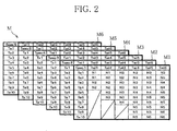
FIG. 2 is a schematic view of a map that is defined by a control unit shown inFIG. 1 ; -
FIG. 3 is a graph chronologically showing changes of a rotational frequency of a fan motor, which are caused by control of the rotational frequency of the fan motor when outside air temperature is varied under the condition where preset leaving water temperature of tank water that is supplied from a water heating path and entering water temperature of the tank water entering a water heat exchanger are fixed; -
FIG. 4 is a graph chronologically showing changes of the rotational frequency of the fan motor, which are caused by control of the rotational frequency of the fan motor when the entering water temperature of the tank water entering the water heat exchanger is varied under the condition where the preset leaving water temperature of the tank water that is supplied from the water heating path and the outside air temperature are fixed; and -
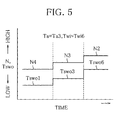
FIG. 5 is a graph chronologically showing changes of the rotational frequency of the fan motor, which are caused by control of the rotational frequency of the fan motor when the preset leaving water temperature of the tank water supplied from the water heating path is varied under the condition where the outside air temperature and the entering water temperature of the tank water entering the water heat exchanger are fixed. - One embodiment of the invention will be described below with reference to the attached drawings.
-
FIG. 1 schematically shows awater heater 1. Thewater heater 1 is formed largely of aheat pump unit 2 and awater heating unit 4. Theunits water heat exchanger 6. - The
heat pump unit 2 has arefrigerant circulation path 8 through which a refrigerant consisting, for example, of CO2 flows. Interposed in therefrigerant circulation path 8 are anatmospheric heat exchanger 10 that exchanges heat between atmospheric air and the refrigerant, acompressor 12, awater heat exchanger 6, anexpansion valve 14, and the like, in the order named. Theatmospheric heat exchanger 10 has afan 11 formed of a fan motor (hereinafter, referred to as FM) 11a andvanes 11b. - The
water heating unit 4 includes a hot-waterstorage circulation path 16 through which the tank water flows. Interposed in the hot-waterstorage circulation path 16 are thewater heat exchanger 6, a hot-water storage tank 18, acirculation pump 20 and the like, in the order named. Thewater heating unit 4 includes awater supply path 22 that supplies water to the hot-water storage tank 18 and awater heating path 24 that supplies hot water from the hot-water storage tank 18. - In the
heat pump unit 2, theatmospheric heat exchanger 10 exchanges heat between the atmospheric air sent by thefan 11 and the refrigerant flowing through therefrigerant circulation path 8 of theheat pump unit 2. In this manner, atmospheric heat is introduced into the refrigerant, and the refrigerant is thus heated. Thewater heat exchanger 6 subsequently exchanges heat between the heated refrigerant and the tank water flowing through the hot-waterstorage circulation path 16 of thewater heating unit 4. The heat of the refrigerant is introduced into the tank water so that the tank water is heated up to given leaving water temperature. - In the
water heating unit 4, when thecirculation pump 20 is driven, city water that is supplied from thewater supply path 22 is circulated through the hot-waterstorage circulation path 16 as tank water. The tank water heated up to the given leaving water temperature in thewater heat exchanger 6 as described above is discharged from thewater heating path 24, and is used for various purposes. - The hot-water
storage circulation path 16 is provided with an entering water temperature sensor (entering-water-temperature detecting means) 26 that detects entering water temperature Twi of the tank water entering thewater heat exchanger 6. Thewater heater 1 is provided with an outside air temperature sensor (outside-air-temperature detecting means) 28 that detects the temperature of the atmospheric air sent by thefan 11, that is, outside air temperature Ta. - Not only the
temperature sensors FM 11a but also a drive member of thecompressor 12 and that of theexpansion valve 14 are electrically connected to acontrol unit 30 that controls the water heater 1 (electrical connections other than those of thecontrol unit 30 to thetemperature sensors FM 11a are not shown). - The
control unit 30 is electrically connected with a setting unit (leaving-water-temperature setting means) 32 that carries out various setting of thewater heater 1. According to thesetting unit 32, for example, if the user of thewater heater 1 sets preset leaving water temperature Tswo of the tank water, thecontrol unit 30 drives thecompressor 12, changes the rotational frequency of thecompressor 12, and also changes an opening angle of theexpansion valve 14 according to the entering water temperature Twi and the outside air temperature Ta that are detected by thetemperature sensors control unit 30 furthermore drives theFM 11a and changes a rotational frequency N of theFM 11a, to thereby discharge the tank water heated up to desired leaving water temperature Two from thewater heating path 24. - To be concrete, as shown in
FIG. 2 , the FM rotational frequency N is determined by map M defined by thecontrol unit 30. - The map M is formed, for example, of maps M1 to M6 corresponding to preset leaving water temperatures Tswo1 to Tswo6 (Tswo1<Tswo2<Tswo3<Tswo4<Tswo5<Tswo6). Based upon the maps M1 to M6, the FM rotational frequency N is determined according to the detected entering water temperature Twi and the detected outside air temperature Ta.
- For instance, the FM rotational frequency N is divided into steps, namely N1 to N6 (N1>N2>N3>N4>N5>N6). The entering water temperature Twi is divided into temperature ranges Twi1 to Twi6 (Twi1<Twi2<Twi3<Twi4<Twi5<Twi6). The outside air temperature Ta is divided into temperature ranges Ta1 to Ta10 (Ta1<Ta2<Ta3<Ta4<Ta5<Ta6<Ta7<Ta8<Ta9<Ta10). When the
setting unit 32 selects one of the preset leaving water temperatures Tswo1 to Tswo6, within the corresponding one of the maps M1 to M6, it is determined which one of the temperature ranges Twi1 to Twi6 the detected entering water temperature Twi falls in and which one of the temperature ranges Ta1 to Ta6 the detected outside air temperature Ta falls in. TheFM 11a is driven at one of the FM rotational frequencies N1 to N6 which are determined according to the map M. - At the stage of preparing the maps M1 to M6, environmental load Qf to which the
heat pump unit 2 is exposed is calculated into Qf1 to Qf6 correspondingly to the preset leaving water temperatures Tswo1 to Tswo6 according to the following skeleton formulae on the basis of the detected entering water temperature Twi and the detected outside air temperature Ta.


- The environmental load Qf is calculated on the basis of the entering water temperature Twi, the outside air temperature Ta, and the preset leaving water temperature Tswo. The environmental load Qf is increased along with increase of the entering water temperature Twi or the outside air temperature Ta.
- Coefficient A and coefficients B1 to B6 in the skeleton formulae are properly determined according to specifications of the
water heater 1. The coefficients B1 to B6 satisfy a relational expression B1>B2>B3>B4>B5>B6. Therefore, under the condition where the entering water temperature Twi and the outside air temperature Ta are fixed, a relational expression Qf1>Qf2>Qf3>Qf4>Qf5>Qf6 is satisfied, and the environmental load Qf is reduced as the preset leaving water temperature Tswo is increased. - According to which environmental load Qf (Qf1 to Qf6) corresponds to which relational expression below, the FM rotational frequencies N1 to N6 are allocated so that the COP of the
water heater 1 is most suitable.


- Values X1 to X4 used in the above relational expressions are properly determined according to the specifications of the
water heater 1. A relational expression X1<X2<X3<X4 is satisfied. Therefore, the FM rotational frequency N is increased as the environmental load Qf is reduced. In other words, the map M is prepared to increase the FM rotational frequency N along with the decrease of the entering water temperature Twi or the outside air temperature Ta, or along with the increase of the preset leaving water temperature Tswo. - The FM rotational frequency control that is implemented by the
control unit 30 using the map M will be described in details with reference toFIGS. 3 to 5 . -
FIG. 3 is a graph chronologically showing changes of the FM rotational frequency N, which are caused by the FM rotational frequency control when the outside air temperature Ta is varied under the condition where the preset leaving water temperature Tswo and the entering water temperature Twi are fixed to Tswo1 and Twi2, respectively. - When the outside air temperature Ta drops from Ta6 to Ta5 and then rises to Ta6 again, the FM rotational frequency control increases the FM rotational frequency N from N3 to N2 in stages, and reduces the FM rotational frequency N to N3 again in response to the changes of the outside air temperature Ta on the basis of the map M.
-
FIG. 4 is a graph chronologically showing changes of the FM rotational frequency N, which are caused by the FM rotational frequency control when the entering water temperature Twi is varied under the condition where the preset leaving water temperature Tswo and the outside air temperature Ta are fixed to Tswo1 and Ta4, respectively. - When the entering water temperature Twi rises from Twi2 to Twi4 then to Twi5, the FM rotational frequency control decreases the FM rotational frequency N from N2 to N3 and then to N4 in stages on the basis of the map M in response to the changes of the entering water temperature Twi.
-
FIG. 5 is a graph chronologically showing changes of the FM rotational frequency N, which are caused by the FM rotational frequency control when the preset leaving water temperature Tswo is varied under the condition where the outside air temperature Ta and the entering water temperature Twi are fixed to Ta3 and Twi6, respectively. - The FM rotational frequency control increases the FM rotational frequency N from N4 to N3 and then to N2 in stages when the user operates the setting
unit 32 to increase the preset leaving water temperature Tswo from Tswo1 to Tswo3 and then to Tswo6. - The above-described FM rotational frequency control is started with the FM rotational frequency N determined by the entering water temperature Twi and the outside air temperature Ta, which are detected at the start of the operation of the
water heater 1, and the preset leaving water temperature Tswo. After that, the FM rotational frequency control is continuously carried out by updating the FM rotational frequency N with a given control period and on given conditions. - When the environmental load Qf is reduced in response to the decrease of the entering water temperature Twi or the outside air temperature Ta, or in response to the increase of the preset leaving water temperature Tswo, the present embodiment gradually increases
FM 11a up to the FM rotational frequency N that offers the optimum COP of thewater heater 1 as described above. That is to say, the environmental load Qf, which is calculated on the basis of all parameters related to the interior, exterior and operation of theheat pump unit 2, is used as a parameter that determines the FM rotational frequency N of the FM rotational frequency control. - The COP of the
water heater 1 can be remarkably improved by carrying out the heat exchange between the refrigerant in theheat pump unit 2 and the tank water in thewater heating unit 4, and by using, as a determining factor of the FM rotational frequency N, the entering water temperature Twi serving as the parameter related directly to the heat exchange of thewater heat exchanger 6 that is an important constituent when determining the COP of thewater heater 1. - If the temperature of the tank water supplied to the
water heating unit 4, the entering water temperature Twi or the outside air temperature Ta is varied, or if the preset leaving water temperature Tswo is changed by the user, the gradual control of FM rotational frequency N makes it possible to smoothly and stably introduce the atmospheric heat into the refrigerant and thus the tank water in stages according to the operation condition of thewater heater 1. Consequently, the COP of thewater heater 1 can be reliably improved. - When the atmospheric heat is not necessary in summer where the outside air temperature Ta is high, the FM rotational frequency N can be kept low by gradually reducing the FM rotational frequency N along with the increase of the entering water temperature Twi. It is then possible to suppress the power consumption and noise of the
fan 11 and reduce the load applied to thecompressor 12. At the same time, it is also possible to provide the desired leaving water temperature Two, namely an endothermic amount that is required in theatmospheric heat exchanger 10 and thus thewater heat exchanger 6, while driving theFM 11a with the optimum FM rotational frequency N. - In winter where the outside air temperature Ta is low, the
FM 11a can be driven by the optimum FM rotational frequency N. Theatmospheric heat exchanger 10 therefore properly operates and may be retarded in defrost timing. - This is the end of the descriptions about the one embodiment of the invention. However, the invention is not limited to this embodiment, and may be modified in various ways without deviating from the gist of the invention.
- For example, the embodiment uses the map to determine the FM rotational frequency N, but the map does not necessarily have to be used. On the contrary, the FM rotational frequency N may be determined by using an arithmetic expression.
- In addition, the refrigerant does not necessarily have to be CO2 gas as in the embodiment. Nevertheless, to use CO2 gas as refrigerant can both reduce the load applied to the global environment and achieve the above-mentioned operation and advantages.
Claims (6)
- A water heater (1) comprising:an atmospheric heat exchanger (10) that exchanges heat between atmospheric air sent by a fan (11) and a refrigerant flowing through a refrigerant circulation path (8) of a heat pump unit (2) to heat the refrigerant;a water heat exchanger (6) that exchanges heat between the refrigerant that has passed through the atmospheric heat exchanger (10) and tank water flowing through a hot-water storage circulation path (16) of a water heating unit (4) to heat the tank water up to given leaving water temperature;entering-water-temperature detecting means (26) that detects entering water temperature of the tank water entering the water heat exchanger (6); anda control unit (30) that drives the fan (11),characterized in that:the control unit (30) changes a rotational frequency of the fan (11) according to the entering water temperature that is detected by the entering-water-temperature detecting means (26).
- The water heater (1) according to claim 1,
characterized in that:the control unit (30) reduces the rotational frequency of the fan (11) in stages along with increase of the entering water temperature. - The water heater (1) according to either one of claims 1 and 2, further including:outside-air-temperature detecting means (28) that detects outside air temperature, characterized in that:the control unit (30) increases the rotational frequency of the fan (11) in stages along with decrease of the outside air temperature that is detected by the outside-air-temperature detecting means (28).
- The water heater (1) according to any one of claims 1 to 3, further including:leaving-water-temperature setting means (32) that sets preset leaving water temperature to heat the tank water up to the given leaving water temperature with the water heat exchanger (6), characterized in that:the control unit (30) increases the rotational frequency of the fan (11) in stages along with the increase of the preset leaving water temperature.
- The water heater (1) according to claim 4,
characterized in that:the control unit (30) calculates an environmental load to which the heat pump unit (2) is exposed, on the basis of the entering water temperature, the outside air temperature, and the preset leaving water temperature, and increases the rotational frequency of the fan (11) in stages along with decrease of the environmental load. - The water heater (1) according to any one of claims 1 to 5, characterized in that:the refrigerant is CO2 gas.
Applications Claiming Priority (1)
| Application Number | Priority Date | Filing Date | Title |
|---|---|---|---|
| JP2007168858A JP2009008308A (en) | 2007-06-27 | 2007-06-27 | Water heater |
Publications (1)
| Publication Number | Publication Date |
|---|---|
| EP2009370A1 true EP2009370A1 (en) | 2008-12-31 |
Family
ID=39769515
Family Applications (1)
| Application Number | Title | Priority Date | Filing Date |
|---|---|---|---|
| EP08011610A Withdrawn EP2009370A1 (en) | 2007-06-27 | 2008-06-26 | Water heater |
Country Status (2)
| Country | Link |
|---|---|
| EP (1) | EP2009370A1 (en) |
| JP (1) | JP2009008308A (en) |
Cited By (8)
| Publication number | Priority date | Publication date | Assignee | Title |
|---|---|---|---|---|
| CN102269445A (en) * | 2011-07-19 | 2011-12-07 | 史雪梅 | Heating system energy-saving control device |
| CN103307654A (en) * | 2012-03-12 | 2013-09-18 | 松下电器产业株式会社 | Heat pump hydronic heater |
| EP2559953A4 (en) * | 2010-04-15 | 2013-12-18 | Mitsubishi Electric Corp | CONTROL UNIT FOR A WATER HEATER SYSTEM, PROGRAM FOR CONTROLLING THE WATER HEATER SYSTEM AND OPERATING METHOD FOR THE WATER HEATER SYSTEM |
| EP3051224A4 (en) * | 2013-09-27 | 2017-05-31 | Mitsubishi Electric Corporation | Refrigeration cycle device |
| CN109780723A (en) * | 2017-11-13 | 2019-05-21 | 游素月 | CO2 heat application device |
| CN111678254A (en) * | 2020-06-03 | 2020-09-18 | 青岛海信日立空调系统有限公司 | Air source heat pump unit |
| EP3889518A4 (en) * | 2018-11-29 | 2022-02-09 | Qingdao Economic and Technological Development Zone Haier Water Heater Co., Ltd. | CONTROL METHOD FOR HEAT PUMP WATER HEATER AND HEAT PUMP WATER HEATER |
| EP2400229B1 (en) * | 2010-06-24 | 2022-10-19 | STIEBEL ELTRON GmbH & Co. KG | Method for operating a heat pump unit and heat pump unit |
Families Citing this family (4)
| Publication number | Priority date | Publication date | Assignee | Title |
|---|---|---|---|---|
| JP5134446B2 (en) * | 2008-06-10 | 2013-01-30 | 株式会社コロナ | Heat pump type water heater |
| JP2010133598A (en) * | 2008-12-03 | 2010-06-17 | Daikin Ind Ltd | Heat pump type water heater |
| JP2010169350A (en) * | 2009-01-26 | 2010-08-05 | Mitsubishi Electric Corp | Heat pump type water heater |
| JP5940378B2 (en) * | 2012-06-01 | 2016-06-29 | 株式会社東芝 | MRI apparatus unit cooling apparatus and MRI apparatus |
Citations (5)
| Publication number | Priority date | Publication date | Assignee | Title |
|---|---|---|---|---|
| JP2003161545A (en) | 2001-11-28 | 2003-06-06 | Daikin Ind Ltd | Heat pump water heater |
| JP2003222396A (en) * | 2002-01-30 | 2003-08-08 | Daikin Ind Ltd | Heat pump water heater |
| JP2005121284A (en) * | 2003-10-16 | 2005-05-12 | Matsushita Electric Ind Co Ltd | Heat pump water heater |
| JP2005156030A (en) * | 2003-11-26 | 2005-06-16 | Hitachi Home & Life Solutions Inc | Heat pump apparatus |
| EP1655558A1 (en) * | 2004-11-04 | 2006-05-10 | Matsushita Electric Industries Co., Ltd. | Control method of refrigeration cycle apparatus and refrigeration cycle apparatus using the control method |
Family Cites Families (3)
| Publication number | Priority date | Publication date | Assignee | Title |
|---|---|---|---|---|
| JPH0777355A (en) * | 1993-09-06 | 1995-03-20 | Toto Ltd | Hot water feeding device with one boiler and two water passages |
| JP2004309084A (en) * | 2003-04-10 | 2004-11-04 | Matsushita Electric Ind Co Ltd | Heat pump water heater |
| JP4552836B2 (en) * | 2005-11-16 | 2010-09-29 | 株式会社デンソー | Heat pump type water heater |
-
2007
- 2007-06-27 JP JP2007168858A patent/JP2009008308A/en active Pending
-
2008
- 2008-06-26 EP EP08011610A patent/EP2009370A1/en not_active Withdrawn
Patent Citations (5)
| Publication number | Priority date | Publication date | Assignee | Title |
|---|---|---|---|---|
| JP2003161545A (en) | 2001-11-28 | 2003-06-06 | Daikin Ind Ltd | Heat pump water heater |
| JP2003222396A (en) * | 2002-01-30 | 2003-08-08 | Daikin Ind Ltd | Heat pump water heater |
| JP2005121284A (en) * | 2003-10-16 | 2005-05-12 | Matsushita Electric Ind Co Ltd | Heat pump water heater |
| JP2005156030A (en) * | 2003-11-26 | 2005-06-16 | Hitachi Home & Life Solutions Inc | Heat pump apparatus |
| EP1655558A1 (en) * | 2004-11-04 | 2006-05-10 | Matsushita Electric Industries Co., Ltd. | Control method of refrigeration cycle apparatus and refrigeration cycle apparatus using the control method |
Cited By (10)
| Publication number | Priority date | Publication date | Assignee | Title |
|---|---|---|---|---|
| EP2559953A4 (en) * | 2010-04-15 | 2013-12-18 | Mitsubishi Electric Corp | CONTROL UNIT FOR A WATER HEATER SYSTEM, PROGRAM FOR CONTROLLING THE WATER HEATER SYSTEM AND OPERATING METHOD FOR THE WATER HEATER SYSTEM |
| US9562696B2 (en) | 2010-04-15 | 2017-02-07 | Mitsubishi Electric Corporation | Hot water supply system control apparatus and hot water supply system control program and hot water supply system operating method |
| EP2400229B1 (en) * | 2010-06-24 | 2022-10-19 | STIEBEL ELTRON GmbH & Co. KG | Method for operating a heat pump unit and heat pump unit |
| CN102269445A (en) * | 2011-07-19 | 2011-12-07 | 史雪梅 | Heating system energy-saving control device |
| CN103307654A (en) * | 2012-03-12 | 2013-09-18 | 松下电器产业株式会社 | Heat pump hydronic heater |
| CN103307654B (en) * | 2012-03-12 | 2017-05-31 | 松下电器产业株式会社 | Heat pump type hot water heating system |
| EP3051224A4 (en) * | 2013-09-27 | 2017-05-31 | Mitsubishi Electric Corporation | Refrigeration cycle device |
| CN109780723A (en) * | 2017-11-13 | 2019-05-21 | 游素月 | CO2 heat application device |
| EP3889518A4 (en) * | 2018-11-29 | 2022-02-09 | Qingdao Economic and Technological Development Zone Haier Water Heater Co., Ltd. | CONTROL METHOD FOR HEAT PUMP WATER HEATER AND HEAT PUMP WATER HEATER |
| CN111678254A (en) * | 2020-06-03 | 2020-09-18 | 青岛海信日立空调系统有限公司 | Air source heat pump unit |
Also Published As
| Publication number | Publication date |
|---|---|
| JP2009008308A (en) | 2009-01-15 |
Similar Documents
| Publication | Publication Date | Title |
|---|---|---|
| JP2009008308A (en) | Water heater | |
| CN107300231B (en) | Heat pump unit and control method and device thereof | |
| US6467289B2 (en) | Hot-water supply system with heat pump cycle | |
| CN103912990B (en) | A kind of control method of Teat pump boiler | |
| JP2831838B2 (en) | Air conditioner | |
| CN101946132A (en) | Heat pump type water heater | |
| JPH06241595A (en) | Heat pump system and control method of operation thereof | |
| CN105571068A (en) | Operation control method and device for air conditioner | |
| JP7295779B2 (en) | Heat pump hot water heating system | |
| WO2010119142A2 (en) | An energy system with a heat pump | |
| CN103913024B (en) | For the method controlling the speed of variable speed compressor | |
| US20150068237A1 (en) | Air conditioner | |
| CN107024046A (en) | A kind of air-conditioner control method and air conditioner | |
| US9696067B2 (en) | Apparatus and method for controlling indoor airflow for heat pumps | |
| CN106500255A (en) | A kind of air-conditioning equipment, blower fan system and blower fan system control method | |
| CN110207340A (en) | The new blower of Total heat exchange and its control method | |
| JP2011089707A (en) | Hot water storage type water heater, and control method of hot water storage type water heater | |
| EP3705808B1 (en) | Air conditioner | |
| CN105928209A (en) | Heat pump water heater and defrosting control method and device thereof | |
| CN113418283B (en) | Control method for air conditioner | |
| JPS60159566A (en) | Controller for operation of air conditioner | |
| JP2008020147A (en) | Heat pump water heater | |
| CN109827269A (en) | A kind of cold outdoor fan control method of indirect evaporation and control device | |
| CN101095019A (en) | A cooling device and a control method | |
| CN110454934A (en) | Air conditioner, its control method, and control device |
Legal Events
| Date | Code | Title | Description |
|---|---|---|---|
| PUAI | Public reference made under article 153(3) epc to a published international application that has entered the european phase |
Free format text: ORIGINAL CODE: 0009012 |
|
| AK | Designated contracting states |
Kind code of ref document: A1 Designated state(s): AT BE BG CH CY CZ DE DK EE ES FI FR GB GR HR HU IE IS IT LI LT LU LV MC MT NL NO PL PT RO SE SI SK TR |
|
| AX | Request for extension of the european patent |
Extension state: AL BA MK RS |
|
| 17P | Request for examination filed |
Effective date: 20090420 |
|
| 17Q | First examination report despatched |
Effective date: 20090527 |
|
| AKX | Designation fees paid |
Designated state(s): DE FR |
|
| GRAP | Despatch of communication of intention to grant a patent |
Free format text: ORIGINAL CODE: EPIDOSNIGR1 |
|
| STAA | Information on the status of an ep patent application or granted ep patent |
Free format text: STATUS: THE APPLICATION IS DEEMED TO BE WITHDRAWN |
|
| 18D | Application deemed to be withdrawn |
Effective date: 20101223 |