EP2009297A1 - A device for indicating the tension in a fastening member, such as a screw or the like - Google Patents
A device for indicating the tension in a fastening member, such as a screw or the like Download PDFInfo
- Publication number
- EP2009297A1 EP2009297A1 EP07111060A EP07111060A EP2009297A1 EP 2009297 A1 EP2009297 A1 EP 2009297A1 EP 07111060 A EP07111060 A EP 07111060A EP 07111060 A EP07111060 A EP 07111060A EP 2009297 A1 EP2009297 A1 EP 2009297A1
- Authority
- EP
- European Patent Office
- Prior art keywords
- tension
- support member
- spring member
- indicating
- indicator means
- Prior art date
- Legal status (The legal status is an assumption and is not a legal conclusion. Google has not performed a legal analysis and makes no representation as to the accuracy of the status listed.)
- Withdrawn
Links
- 238000005452 bending Methods 0.000 claims abstract description 11
- 230000002427 irreversible effect Effects 0.000 claims abstract description 4
- 238000000034 method Methods 0.000 claims abstract description 4
- 230000014759 maintenance of location Effects 0.000 claims description 16
- 238000006073 displacement reaction Methods 0.000 claims description 11
- 238000009413 insulation Methods 0.000 description 12
- 239000000463 material Substances 0.000 description 9
- 239000012774 insulation material Substances 0.000 description 8
- 229910052751 metal Inorganic materials 0.000 description 4
- 239000002184 metal Substances 0.000 description 4
- 229910000831 Steel Inorganic materials 0.000 description 2
- 239000011449 brick Substances 0.000 description 2
- 230000000694 effects Effects 0.000 description 2
- 238000010079 rubber tapping Methods 0.000 description 2
- 239000010959 steel Substances 0.000 description 2
- 230000002411 adverse Effects 0.000 description 1
- 238000004873 anchoring Methods 0.000 description 1
- 230000005489 elastic deformation Effects 0.000 description 1
- 238000007689 inspection Methods 0.000 description 1
- 229910001092 metal group alloy Inorganic materials 0.000 description 1
- 239000007769 metal material Substances 0.000 description 1
- 150000002739 metals Chemical class 0.000 description 1
- 230000000717 retained effect Effects 0.000 description 1
- 229920003002 synthetic resin Polymers 0.000 description 1
- 239000000057 synthetic resin Substances 0.000 description 1
Images


Classifications
-
- F—MECHANICAL ENGINEERING; LIGHTING; HEATING; WEAPONS; BLASTING
- F16—ENGINEERING ELEMENTS AND UNITS; GENERAL MEASURES FOR PRODUCING AND MAINTAINING EFFECTIVE FUNCTIONING OF MACHINES OR INSTALLATIONS; THERMAL INSULATION IN GENERAL
- F16B—DEVICES FOR FASTENING OR SECURING CONSTRUCTIONAL ELEMENTS OR MACHINE PARTS TOGETHER, e.g. NAILS, BOLTS, CIRCLIPS, CLAMPS, CLIPS OR WEDGES; JOINTS OR JOINTING
- F16B31/00—Screwed connections specially modified in view of tensile load; Break-bolts
- F16B31/02—Screwed connections specially modified in view of tensile load; Break-bolts for indicating the attainment of a particular tensile load or limiting tensile load
- F16B31/028—Screwed connections specially modified in view of tensile load; Break-bolts for indicating the attainment of a particular tensile load or limiting tensile load with a load-indicating washer or washer assembly
Definitions
- the present invention relates to a device for indicating the tension in a fastening member, such as a screw or the like, said device comprising a spring member having a first sheet portion with a fastening member receiving aperture; a second sheet portion, and a joining bending portion connecting said first and second sheet portions, so that the first and second portions are biased towards each other by the head of the fastening member in response to the tightening of said fastening member.
- the invention also relates to a mounting system with one or more of such devices.
- a tension indicating device which has an indicating arm and reference means carried by a stamped generally frustoconical spring washer.
- the arm and the reference means mechanically engage each other and the arm is designed to be visually discernable from a distance in response to the tension of a screw as the frustoconical spring washer is flattened due to tightening of the screw whereby the arm is loosened from its engagement with the reference means.
- the apparatus includes a washer and a ring of a generally flat synthetic resin sheet.
- the washer includes a pair of washer portions of a generally flat, round shape and a joint portion interconnecting the washer portions to face them in opposite directions to enable the washer portions to receive a shank of a screw in the openings thereof.
- the lengthwise section of the joint portion forms generally a U shape.
- the ring is made of a generally round, deformable material and is inserted between the pair of washer portions thus facing each other. The deformable material is expanded radially outward, when compressed by the washer portions receiving the shank of the screw when fastened. Upon the compressive force reaching a predetermined value, the ring will be broken due to the pair of washer portions overlaying one another.
- the known tension indicating devices are able to indicate if a screw is incompletely fastened as a first part is mounted onto a second part. Furthermore there is known that for some purposes, the two parts must be mounted to one another with a predetermined tension in the screw. For this purpose, torque indication tools are provided to ensure that the screw is not mounted with excessive tension, so that damage of the parts may be prevented.
- a tension indicating device of the initially mentioned kind wherein said device is provided with first tension indicator means indicating the tension in the elongated fastener by indicating the relative displacement between the first and second sheet portions at least until the tension exceeds a first predetermined tension value.
- the device is also provided with irreversible second tension indicator means for indicating if the tension in the elongated fastener during the mounting process has been exposed to a tension exceeded a second predetermined tension value, where said second tension is higher than said first tension value.
- the invention provides a tension indicating device which is suitable for mounting elements, such as building cover panels, onto a concrete wall or the like, where the receiving inner part, such as a concrete or brick wall, is likely to be damaged if the screw is tightened too much, i.e. provided with too much tension. This may cause the brittle concrete or brick wall to be deteriorated in the hole which is produced by a self-tapping screw.
- the tension indicating device will leave a permanent visible indication about the tension in the screw, and it can therefore be visibly seen, if the particular screw cannot be expected to contribute sufficiently to the retention of the first part onto the second part.
- the invention is advantageous in relation to an insulating wall system for a building structure of the kind disclosed in PCT/EP2007/002791 (not yet published) where the wall system comprises an inner wall having an exterior surface with insulation material attached to said exterior surface of said inner wall by elongated fastening members, such as screws, extending through at least one insulation mounting profile and the insulation material so that the insulation material is fixed to the first wall, wherein elongated fastening members are mounted substantially perpendicular to the exterior surface of the inner wall and wherein the elongated fastening members are mounted prestressed with a predetermined amount of tension so that frictional forces between the insulation member and the inner wall and the one or more outer wall members, respectively, are provided.
- elongated fastening members such as screws
- frictional forces between the insulation member and the first wall and the second wall, respectively are provided that are sufficient to transfer the weight of the second wall to the first wall exclusively by establishing a friction force between the insulation and the second wall and between the insulation and the first wall.
- a tension indicating washer device which can visibly indicate the tension in a screw, and in particular if a screw has been excessively tension loaded during the mounting. This will enable an inspection to reveal any poorly mounted screws in the mounting of an insulation carrying sub-structure for a building façade, so that any such poorly mounted screws may be replaced.
- the first and second tension indicator means indicate an angular displacement of the first portion relative to the second portion of the spring member.
- the first and second portions are angularly displaced and bent towards each other as the spring member is substantially U-shaped.
- the displacement of the first portion relative to the second portion is indicative of the tension in the screw.
- the first portion is provided with an indicator at its distal end opposite the bending portion cooperating with the first and second tension indicator means respectively for indicating the displacement between the first and second portions of the spring members.
- This indicator may be a tap at the distal end and the first tension indicator means may further include at least one alignment element adjacent the indicator on the first portion. When the indicator tap is aligned with the at least one alignment element, the correct tension in the screw is obtained.
- the second indicator means preferably include a tear-off element, preferably mounted between two alignment elements of the first tension indicator means, this tear-off element is provided such that if the displacement of the indicator tap, i.e.
- the tear-off element of the second indicator means is broken away from the alignment element.
- the absence of this tear-off element will indicate an over-tightened screw which at least at some stage during its mounting had been provided with too much tension and thereby having subjected the anchoring structure in the inner wall (the substructure) to a potential damage.
- the second portion is provided with an aperture, such as a hole or a cut-away, adjacent the fastening member receiving aperture of said first portion.
- the first and second tension indicator means are provided on an indicator support member in which the spring member is accommodated.
- the support member is preferably made in a plastic material whereas the spring member is made in a steel material or similar metal material providing good elastic deformation properties and with a superior stiffness of the indicator tap relative to the material and the design of the tear-off element on the support member.
- the support member being in a plastic material is advantageous since the support member thereby is thermally insulating the spring member. Thus, the support member is preventing a thermal bridge between the profiles on the outside of the insulation and the inner wall.
- the second portion of the spring member is provided with one or more attachment means cooperating with retention means provided on the support member, said attachment means preferably including a set of retention hook-like members of said support member engaging cooperating retention apertures in the second sheet portion of the spring member.
- said attachment means preferably including a set of retention hook-like members of said support member engaging cooperating retention apertures in the second sheet portion of the spring member.
- said first and second indication means are provided opposite to said bending portion relative to the fastening member receiving aperture.
- a good spring effect involving sufficient relative displacement between the first and second portions of the leaf-spring-like spring member is achieved in order to provide an accurate tension indication of the screw.
- the support member is provided with a fastener support cylindrical portion at least having a first protrusion for accommodating the aperture of the second portion of the spring member.
- said first protrusion is provided with retention elements for retaining said spring member in a predetermined position in the support member and relative to the first and second indicator means on said support member.
- the support member is preferably provided with a second protrusion projecting in the opposite direction relative to the first protrusion, wherein said second protrusion is provided with an external diameter adapted for being accommodated in the mounting holes in the base profile.
- a mounting system comprising an elongated mounting profile comprising a base portion and two side flanges projecting out of the plane of the base portion defining the internal width of said base portion, and said base portion being provided with mounting holes for receiving a fastening screw; a device for indicating the tension in a fastening member, such as a screw or the like, said device comprising a spring member having a first sheet portion with a fastening member receiving aperture; a second sheet portion, and a joining bending portion connecting said first and second sheet portions, so that the first and second portions are biased towards each other by the head of the fastening member in response to the tightening of said fastening member, wherein said device is provided with first tension indicator means indicating the tension in the elongated fastener at least until the tension exceeds a first predetermined tension value.
- the advantage of a preferred device according to the first aspect of the invention is that the tension indicating device may be pre-mounted in the profiles before the fasting screws are inserted through the profiles. Moreover, by providing the first and second tension indicator means on an indicator support member in which the spring member is accommodated and when the support member is provided with a width which is less than the internal width of said base portion of the elongated mounting profile, an accurate fit of the tension indicating device in the mounting profile is achieved.
- the tension indicating device comprises to parts: a spring member 1 and a support member 2.
- the spring member 1 is a generally U-shaped bent sheet metal and comprises a first sheet portion 11 and a second sheet portion 12 jointed by a bending portion 13.
- an indicator tap 14 which is formed as an extension of the sheet metal of the first portion 11.
- the first and second portions 11, 12 of the spring member 1 are provided with a mutual angular diversion.
- the first portion 11 may be biased towards the second portion 12 when the spring member 1 is subjected to a load as a screw is provided through the fastener receiving hole 15 provided adjacent the distal end of the first portion 11, such as shown in figure 1 . Adjacent the receiving hole 15, a cut-away aperture 16 is provided in the distal end of the second sheet portion 12.
- the spring member 1 is designed such that when the desired tension of the screw is achieved, the first and second portions 11, 12 are preferably biased into a parallel position relative to each other.
- the support member 2 comprises a support portion 29 onto which the second portion 12 of the spring member 1 is accommodated.
- a reference portion 28 is provided at one end of the support portion 29, said reference portion 28 being substantially perpendicular to the support portion 29 and dimensioned so that the distal end of the second portion 12 of the spring member 1 preferably abuts the foot of the reference portion 28 when mounted correctly in the support member 2.
- the support portion 29 is preferably provided with protruding elements 26 which cooperate with associated openings 17 in the second portion 12.
- the support member 2 is also provided with a fastener receiving opening 27, preferably including an upwardly extending protrusion 23 with retention elements for retaining the second portion 12 of the spring member 1 in the support member.
- an outwardly protruding second protrusion 24 with profile retention elements 25 is also provided projecting in a perpendicular direction relative to the support portion 29 and in the opposite direction as the first protrusion 23.
- the support member 2 is preferably made in a plastic material which is advantageous since the support member 2 thereby is thermally insulating the spring member 2.
- the support member 2 is preventing a thermal bridge between the profiles 4 on the outside of the insulation 5 and the inner wall 6 (see figures 5 and 6 ), when it is used in a façade system of this kind.
- the reference portion 28 includes two side portions each having a reference surface 21 at their distal ends and said reference surface 21 being provided with a predetermined reference distance to the inner surface of the support portion 29. Between the two reference surfaces 21 there is provided a tear-off element 22, which is provided substantially parallel with the inner surface of the support portion 29. The tear-off element 22 is provided at a second distance to the support portion 29 which is smaller than the reference distance. This difference between the reference difference and the second distance is at least equal to the thickness of the indicator tap 14 of the first spring portion 11 of the spring member 1.
- the force required for breaking off the tear-off element 22 is between 700-900 N, while the tension in the mounting screw 3 and thereby the force applied by the spring member 2 at the first predetermined tension value is approx. 500-700 N.
- the force required to tear off the element 22 is not substantially higher than the force required for the fastening member of the mounting system according to the invention.
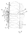
- FIGS 5 and 6 an advantageous use of the tension indicating device according to the invention is shown, where the device is used by the mounting of a profile 4, which holds an insulation material 5 onto an inner wall 6.
- the screws 3 used for such mounting may be self-tapping screws 3 or screws mounted in pre-mounted plugs.
- the profile 4 is preferably a U-profile where the rectangular footprint of the tension indicating device fits into, so that the tension indicating device cannot rotate around the screw when mounted on the profile.
- the device may be pre-mounted in the profile, as the device may be fitted into an opening in the profile 4 as the second outwardly projecting protrusion 24 of the support member 2 is "clicked" into this opening and retained therein by the retention elements 25.
- a mounting screw 3 is then mounted in the mounting hole 15, 27, and pressed and/or screwed through the insulation material 5 and into the inner wall 6, possibly via a plug (not shown).
- the screw head 31 makes contact with the first spring portion 11 of the spring member 1, the spring member 1 is compressed and the indicator tap 14 is pressed towards the second spring portion 12.
- the indicator tap 14 is in level with the reference surface 21 of the support member 2, the correct tension in the screw is achieved, and the profile 4 then presses with the required, predetermined force against the insulation material 5 and the inner wall 6.
- the spring member 1 is preferably made in a steel or other metals or metal alloys with good spring properties and the support member 2 is preferably made in a plastic material. However, other materials may be used without departing from the invention.
- the invention is described with reference to a preferred embodiment.
- other embodiments may be provided without departing from the scope of the invention as defined in the claims.
- the reference surfaces and the tear-off element could be formed in the second spring portion of the spring member 1. Accordingly, it is realised by the invention that according to the scope of the invention as defined in the claims, it is also possible to provide a tension indicating device without a support member.
Landscapes
- Engineering & Computer Science (AREA)
- General Engineering & Computer Science (AREA)
- Mechanical Engineering (AREA)
- Force Measurement Appropriate To Specific Purposes (AREA)
Abstract
The invention concerns a device for indicating the tension in a fastening member, such as a screw (3) or the like, said device comprising a spring member (1) having a first sheet portion (11) with a fastening member receiving aperture (15), a second sheet portion (12), and a joining bending portion (13) connecting said first and second sheet portions, so that the first and second portions are biased towards each other by the head of the fastening member in response to the tightening of said fastening member, wherein said device is provided with first tension indicator means (14) indicating the tension in the elongated fastener at least until the tension exceeds a first predetermined tension value. Moreover, there may be provided irreversible second tension indicator means (22) for indicating if the tension in the elongated fastener during the mounting process has been exposed to a tension exceeded a second predetermined tension value, where said second tension is higher than said first tension value.
Description
- In the present application all references to patents and patent applications are incorporated by reference.
- The present invention relates to a device for indicating the tension in a fastening member, such as a screw or the like, said device comprising a spring member having a first sheet portion with a fastening member receiving aperture; a second sheet portion, and a joining bending portion connecting said first and second sheet portions, so that the first and second portions are biased towards each other by the head of the fastening member in response to the tightening of said fastening member. The invention also relates to a mounting system with one or more of such devices.
- From
US 4,572,717 is known a tension indicating device which has an indicating arm and reference means carried by a stamped generally frustoconical spring washer. The arm and the reference means mechanically engage each other and the arm is designed to be visually discernable from a distance in response to the tension of a screw as the frustoconical spring washer is flattened due to tightening of the screw whereby the arm is loosened from its engagement with the reference means. - From
US 4,988,246 is known an apparatus for indicating incomplete and complete fastening of a screw. The apparatus includes a washer and a ring of a generally flat synthetic resin sheet. The washer includes a pair of washer portions of a generally flat, round shape and a joint portion interconnecting the washer portions to face them in opposite directions to enable the washer portions to receive a shank of a screw in the openings thereof. The lengthwise section of the joint portion forms generally a U shape. The ring is made of a generally round, deformable material and is inserted between the pair of washer portions thus facing each other. The deformable material is expanded radially outward, when compressed by the washer portions receiving the shank of the screw when fastened. Upon the compressive force reaching a predetermined value, the ring will be broken due to the pair of washer portions overlaying one another. - The known tension indicating devices are able to indicate if a screw is incompletely fastened as a first part is mounted onto a second part. Furthermore there is known that for some purposes, the two parts must be mounted to one another with a predetermined tension in the screw. For this purpose, torque indication tools are provided to ensure that the screw is not mounted with excessive tension, so that damage of the parts may be prevented.
- However, by the invention it is realised that these torque limiting mounting tools are insufficient to achieve a satisfactory predetermined tension in the screw. Hence, it is an object of the invention to provide a tension indicating device which is capable of indicating the level of tension that the screw has been loaded with during mounting.
- The object is achieved by a tension indicating device of the initially mentioned kind, wherein said device is provided with first tension indicator means indicating the tension in the elongated fastener by indicating the relative displacement between the first and second sheet portions at least until the tension exceeds a first predetermined tension value.
- Preferably, the device is also provided with irreversible second tension indicator means for indicating if the tension in the elongated fastener during the mounting process has been exposed to a tension exceeded a second predetermined tension value, where said second tension is higher than said first tension value.
- Whereas torque limiting tools are only suitable for mounting screws or bolts with a predetermined tension in metal parts, the invention provides a tension indicating device which is suitable for mounting elements, such as building cover panels, onto a concrete wall or the like, where the receiving inner part, such as a concrete or brick wall, is likely to be damaged if the screw is tightened too much, i.e. provided with too much tension. This may cause the brittle concrete or brick wall to be deteriorated in the hole which is produced by a self-tapping screw. According to the invention, the tension indicating device will leave a permanent visible indication about the tension in the screw, and it can therefore be visibly seen, if the particular screw cannot be expected to contribute sufficiently to the retention of the first part onto the second part.
- In particular, the invention is advantageous in relation to an insulating wall system for a building structure of the kind disclosed in
PCT/EP2007/002791 - In the preferred embodiment, the first and second tension indicator means indicate an angular displacement of the first portion relative to the second portion of the spring member. As the amount of biasing force implied on the spring member caused the spring member to elastically bend, the first and second portions are angularly displaced and bent towards each other as the spring member is substantially U-shaped. Hereby, the displacement of the first portion relative to the second portion is indicative of the tension in the screw.
- In a preferred embodiment, the first portion is provided with an indicator at its distal end opposite the bending portion cooperating with the first and second tension indicator means respectively for indicating the displacement between the first and second portions of the spring members. This indicator may be a tap at the distal end and the first tension indicator means may further include at least one alignment element adjacent the indicator on the first portion. When the indicator tap is aligned with the at least one alignment element, the correct tension in the screw is obtained. As the second indicator means preferably include a tear-off element, preferably mounted between two alignment elements of the first tension indicator means, this tear-off element is provided such that if the displacement of the indicator tap, i.e. the displacement of the first sheet portion, is pressed beyond the alignment of the alignment elements of the first indicator means, the tear-off element of the second indicator means is broken away from the alignment element. The absence of this tear-off element will indicate an over-tightened screw which at least at some stage during its mounting had been provided with too much tension and thereby having subjected the anchoring structure in the inner wall (the substructure) to a potential damage.
- In a preferred embodiment, the second portion is provided with an aperture, such as a hole or a cut-away, adjacent the fastening member receiving aperture of said first portion.
- In the preferred embodiment, the first and second tension indicator means are provided on an indicator support member in which the spring member is accommodated. The support member is preferably made in a plastic material whereas the spring member is made in a steel material or similar metal material providing good elastic deformation properties and with a superior stiffness of the indicator tap relative to the material and the design of the tear-off element on the support member. The support member being in a plastic material is advantageous since the support member thereby is thermally insulating the spring member. Thus, the support member is preventing a thermal bridge between the profiles on the outside of the insulation and the inner wall.
- Preferably, the second portion of the spring member is provided with one or more attachment means cooperating with retention means provided on the support member, said attachment means preferably including a set of retention hook-like members of said support member engaging cooperating retention apertures in the second sheet portion of the spring member. Hereby, it is ensured that the spring member is accommodated in the support member in a predetermined position, whereby the displacement indications of the first and second indicator means are ensured to be correctly indicative of the tension in the fastening member.
- Preferably, said first and second indication means are provided opposite to said bending portion relative to the fastening member receiving aperture. Hereby, a good spring effect involving sufficient relative displacement between the first and second portions of the leaf-spring-like spring member is achieved in order to provide an accurate tension indication of the screw.
- In order to achieve an accurate predetermined position of the spring member in the support member, the support member is provided with a fastener support cylindrical portion at least having a first protrusion for accommodating the aperture of the second portion of the spring member. Moreover, said first protrusion is provided with retention elements for retaining said spring member in a predetermined position in the support member and relative to the first and second indicator means on said support member. Furthermore, the support member is preferably provided with a second protrusion projecting in the opposite direction relative to the first protrusion, wherein said second protrusion is provided with an external diameter adapted for being accommodated in the mounting holes in the base profile.
- In a second aspect of the invention, there is provided a mounting system comprising an elongated mounting profile comprising a base portion and two side flanges projecting out of the plane of the base portion defining the internal width of said base portion, and said base portion being provided with mounting holes for receiving a fastening screw; a device for indicating the tension in a fastening member, such as a screw or the like, said device comprising a spring member having a first sheet portion with a fastening member receiving aperture; a second sheet portion, and a joining bending portion connecting said first and second sheet portions, so that the first and second portions are biased towards each other by the head of the fastening member in response to the tightening of said fastening member, wherein said device is provided with first tension indicator means indicating the tension in the elongated fastener at least until the tension exceeds a first predetermined tension value.
- In a mounting system for a substructure, such as described above, the advantage of a preferred device according to the first aspect of the invention is that the tension indicating device may be pre-mounted in the profiles before the fasting screws are inserted through the profiles. Moreover, by providing the first and second tension indicator means on an indicator support member in which the spring member is accommodated and when the support member is provided with a width which is less than the internal width of said base portion of the elongated mounting profile, an accurate fit of the tension indicating device in the mounting profile is achieved.
- In the following the invention is described in more detail with reference to the accompanying drawings, in which:
- figure 1
- is a perspective view of a tension indicating device according to a preferred embodiment of the invention;
- figure 2
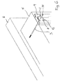
- is a side view of same;
- figure 3
- is a perspective view of a spring member of the device in
figures 1 and 2 ; - figure 4
- is a perspective view of a support member of the device in
figures 1 and 2 ; - figure 5
- is a schematic cross-section view of a mounting system with a tension indicating device according to the invention; and
- figure 6
- is a perspective view thereof.
- With reference to the
figures 1 to 4 , the tension indicating device comprises to parts: aspring member 1 and asupport member 2. Thespring member 1 is a generally U-shaped bent sheet metal and comprises afirst sheet portion 11 and asecond sheet portion 12 jointed by abending portion 13. At the distal end of thefirst portion 11, there is provided anindicator tap 14, which is formed as an extension of the sheet metal of thefirst portion 11. At the unloaded rest position of the spring member 1 (seefigures 1 to 3 ), the first andsecond portions spring member 1 are provided with a mutual angular diversion. Thefirst portion 11 may be biased towards thesecond portion 12 when thespring member 1 is subjected to a load as a screw is provided through thefastener receiving hole 15 provided adjacent the distal end of thefirst portion 11, such as shown infigure 1 . Adjacent the receivinghole 15, a cut-away aperture 16 is provided in the distal end of thesecond sheet portion 12. Thespring member 1 is designed such that when the desired tension of the screw is achieved, the first andsecond portions - The
support member 2 comprises asupport portion 29 onto which thesecond portion 12 of thespring member 1 is accommodated. Areference portion 28 is provided at one end of thesupport portion 29, saidreference portion 28 being substantially perpendicular to thesupport portion 29 and dimensioned so that the distal end of thesecond portion 12 of thespring member 1 preferably abuts the foot of thereference portion 28 when mounted correctly in thesupport member 2. In order to ensure a correct mounting of thespring member 1 in thesupport member 2, thesupport portion 29 is preferably provided withprotruding elements 26 which cooperate with associatedopenings 17 in thesecond portion 12. Thesupport member 2 is also provided with afastener receiving opening 27, preferably including an upwardly extendingprotrusion 23 with retention elements for retaining thesecond portion 12 of thespring member 1 in the support member. Moreover, an outwardly protrudingsecond protrusion 24 withprofile retention elements 25 is also provided projecting in a perpendicular direction relative to thesupport portion 29 and in the opposite direction as thefirst protrusion 23. - The
support member 2 is preferably made in a plastic material which is advantageous since thesupport member 2 thereby is thermally insulating thespring member 2. Thus, thesupport member 2 is preventing a thermal bridge between theprofiles 4 on the outside of theinsulation 5 and the inner wall 6 (seefigures 5 and6 ), when it is used in a façade system of this kind. - The
reference portion 28 includes two side portions each having areference surface 21 at their distal ends and saidreference surface 21 being provided with a predetermined reference distance to the inner surface of thesupport portion 29. Between the tworeference surfaces 21 there is provided a tear-offelement 22, which is provided substantially parallel with the inner surface of thesupport portion 29. The tear-offelement 22 is provided at a second distance to thesupport portion 29 which is smaller than the reference distance. This difference between the reference difference and the second distance is at least equal to the thickness of theindicator tap 14 of thefirst spring portion 11 of thespring member 1. - When a
screw 3 is mounted through theopenings fig. 5 or6 ) thespring member 1 is compressed as the first portion is angular displaced by being biased towards thesecond portion 12. Hereby, theindicator tap 14 on the distal end of thefirst spring portion 11 is being displaced into the gap between the reference surfaces 21 of thereference element 28 on thesupport member 2. When the outer surface of thetap 14 is aligned with the reference surfaces 21, this indicates that the correct tension of thescrew 3 is achieved. If thescrew 3 during its mounting is subjected to a higher tension, which might be an undesired over-tightening, this will cause an extra deflection of thefirst spring portion 11 whereby thetap 14 will be displaced to a position below thereference surface 21, which in turn will cause thetap 14 to make contact with the tear-offelement 22 and apply a pressure on the tear-offelement 22 which will cause the tear-offelement 22 to break off. - In the preferred embodiment, it is found particularly advantageous that the force required for breaking off the tear-off
element 22 is between 700-900 N, while the tension in the mountingscrew 3 and thereby the force applied by thespring member 2 at the first predetermined tension value is approx. 500-700 N. Thus, the force required to tear off theelement 22 is not substantially higher than the force required for the fastening member of the mounting system according to the invention. - In
figures 5 and6 , an advantageous use of the tension indicating device according to the invention is shown, where the device is used by the mounting of aprofile 4, which holds aninsulation material 5 onto aninner wall 6. Thescrews 3 used for such mounting may be self-tappingscrews 3 or screws mounted in pre-mounted plugs. In such substructure for a building cover, it is desirable that thescrews 3 have the correct tension when mounted, so that theinsulation material 5 is pressed against theinner wall 6 with a sufficient force to create the required friction between theinner wall 6 and theinsulation 5. It is important in this application to be able to detect that allscrews 3 have sufficient tension, so that the resulting pressure force between the insulation material and the inner wall has the required value. - The
profile 4 is preferably a U-profile where the rectangular footprint of the tension indicating device fits into, so that the tension indicating device cannot rotate around the screw when mounted on the profile. Moreover, the device may be pre-mounted in the profile, as the device may be fitted into an opening in theprofile 4 as the second outwardly projectingprotrusion 24 of thesupport member 2 is "clicked" into this opening and retained therein by theretention elements 25. - A mounting
screw 3 is then mounted in the mountinghole insulation material 5 and into theinner wall 6, possibly via a plug (not shown). When thescrew head 31 makes contact with thefirst spring portion 11 of thespring member 1, thespring member 1 is compressed and theindicator tap 14 is pressed towards thesecond spring portion 12. When theindicator tap 14 is in level with thereference surface 21 of thesupport member 2, the correct tension in the screw is achieved, and theprofile 4 then presses with the required, predetermined force against theinsulation material 5 and theinner wall 6. - If the mounting
screw 3 is advanced further theindicator tap 14 will press against the tear-offelement 22 which thereby will break off. Thereby, it is visibly clear that thescrew 3 has been tightened more than desired with a potential risk of damaging the mounting hole in the wall. Thespring member 1 is preferably made in a steel or other metals or metal alloys with good spring properties and thesupport member 2 is preferably made in a plastic material. However, other materials may be used without departing from the invention. - Above, the invention is described with reference to a preferred embodiment. However it is realised by the invention that other embodiments may be provided without departing from the scope of the invention as defined in the claims. For instance, as an alternative to the embodiment described above, the reference surfaces and the tear-off element could be formed in the second spring portion of the
spring member 1. Accordingly, it is realised by the invention that according to the scope of the invention as defined in the claims, it is also possible to provide a tension indicating device without a support member.
Claims (20)
- A device for indicating the tension in a fastening member, such as a screw or the like, said device comprising a spring member having
a first sheet portion with a fastening member receiving aperture;
a second sheet portion, and
a joining bending portion connecting said first and second sheet portions, so that the first and second portions are biased towards each other by the head of the fastening member in response to the tightening of said fastening member,
characterised in that
said device is provided with first tension indicator means indicating the tension in the elongated fastener by indicating the relative displacement between the first and second sheet portions at least until the tension exceeds a first predetermined tension value. - A device according to claim 1, wherein the device is provided with irreversible second tension indicator means for indicating if the tension in the elongated fastener during the mounting process has been exposed to a tension exceeded a second predetermined tension value, where said second tension is higher than said first tension value.
- A device according to claim 1 or 2, wherein the first and second tension indicator means indicate an angular displacement of the first portion relative to the second portion of the spring member.
- A device according to any of the preceding claims, wherein the first portion is provided with an indicator at its distal end opposite the bending portion cooperating with the first and second tension indicator means respectively for indicating the displacement between the first and second portions of the spring members.
- A device according to any of the preceding claims, wherein the first tension indicator means includes at least one alignment element adjacent the indicator on the first portion.
- A device according to claim 5, wherein the second indicator means includes a tear-off element, preferably mounted between two alignment elements of the first tension indicator means, adapted for breaking off the indicator means if the tension exceeds the second predetermined tension value.
- A device according to any of the preceding claims, wherein the second portion is provided with an aperture, such as a hole or a cut-away, adjacent the fastening member receiving aperture of said first portion.
- A device according to any of the preceding claims, wherein the first and second tension indicator means are provided on an indicator support member in which the spring member is accommodated.
- A device according to claim 8, wherein the second portion of the spring member is provided with one or more attachment means cooperating with retention means provided on the support member, said attachment means preferably including a set of retention hook-like members of said support member engaging cooperating retention apertures in the second sheet portion of the spring member.
- A device according to any of the preceding claims, wherein said first and second indication means are provided opposite to said bending portion relative to the fastening member receiving aperture.
- A device according to any of claims 8 to 10, wherein the support member is provided with a fastener support cylindrical portion at least having a first protrusion for accommodating the aperture of the second portion of the spring member.
- A device according to claim 11, wherein said first protrusion is provided with retention elements for retaining said spring member in a predetermined position in the support member and relative to the first and second indicator means on said support member.
- A mounting system comprising
an elongated mounting profile comprisinga base portion and two side flanges projecting out of the plane of the base portion defining the internal width of said base portion, and said base portion being provided with mounting holes for receiving a fastening screw;a device for indicating the tension in a fastening member, such as a screw or the like, said device comprising a spring member havinga joining bending portion connecting said first and second sheet portions, so that the first and second portions are biased towards each other by the head of the fastening member in response to the tightening of said fastening member, wherein said device is provided with first tension indicator means indicating the tension in the elongated fastener at least until the tension exceeds a first predetermined tension value.a first sheet portion with a fastening member receiving aperture;a second sheet portion, and - A mounting system according to claim 13, wherein irreversible second tension indicator means are provided for indicating if the tension in the elongated fastener during the mounting process has been exposed to a tension exceeded a second predetermined tension value, where said second tension is higher than said first tension value.
- A mounting system according to claim 14, wherein the first and second tension indicator means are provided on an indicator support member in which the spring member is accommodated and that the support member is provided with a width which is less than the internal width of said base portion of the elongated mounting profile.
- A mounting system according to claim 15, wherein the second portion of the spring member is provided with one or more attachment means cooperating with retention means provided on the support member, said attachment means preferably including a set of retention hook-like members of said support member engaging cooperating retention apertures in the second sheet portion of the spring member.
- A mounting system according to any of claims 13 to 16, wherein said first and second indication means are provided opposite to said bending portion relative to the fastening member receiving aperture.
- A mounting system according to any of claims 13 to 17, wherein the support member is provided with a fastener support cylindrical portion at least having a first protrusion for accommodating the aperture of the second portion of the spring member.
- A mounting system according to claim 18, wherein said first protrusion is provided with retention elements for retaining said spring member in a predetermined position in the support member and relative to the first and second indicator means on said support member.
- A mounting system according to any of claims 13 to 19, wherein the support member is provided with a second protrusion projecting in the opposite direction relative to the first protrusion, said second protrusion being adapted for being accommodated in the mounting holes on the base profile.
Priority Applications (2)
| Application Number | Priority Date | Filing Date | Title |
|---|---|---|---|
| EP07111060A EP2009297A1 (en) | 2007-06-26 | 2007-06-26 | A device for indicating the tension in a fastening member, such as a screw or the like |
| PCT/EP2008/057882 WO2009000776A1 (en) | 2007-06-26 | 2008-06-20 | A device for indicating the tension in a fastening member, such as a screw or the like |
Applications Claiming Priority (1)
| Application Number | Priority Date | Filing Date | Title |
|---|---|---|---|
| EP07111060A EP2009297A1 (en) | 2007-06-26 | 2007-06-26 | A device for indicating the tension in a fastening member, such as a screw or the like |
Publications (1)
| Publication Number | Publication Date |
|---|---|
| EP2009297A1 true EP2009297A1 (en) | 2008-12-31 |
Family
ID=38657562
Family Applications (1)
| Application Number | Title | Priority Date | Filing Date |
|---|---|---|---|
| EP07111060A Withdrawn EP2009297A1 (en) | 2007-06-26 | 2007-06-26 | A device for indicating the tension in a fastening member, such as a screw or the like |
Country Status (1)
| Country | Link |
|---|---|
| EP (1) | EP2009297A1 (en) |
Citations (4)
| Publication number | Priority date | Publication date | Assignee | Title |
|---|---|---|---|---|
| US3329058A (en) * | 1964-04-14 | 1967-07-04 | Cumming James Deans | Tension indicating washer |
| GB2000843A (en) * | 1977-07-05 | 1979-01-17 | Solon Mfg Co | Visual load indicator |
| US4572717A (en) * | 1983-08-04 | 1986-02-25 | Illinois Tool Works Inc. | Tension indicating washer improvements |
| GB2229242A (en) * | 1989-03-17 | 1990-09-19 | Kyodo Denki | Apparatus for indicating completion of fastening of screw components |
-
2007
- 2007-06-26 EP EP07111060A patent/EP2009297A1/en not_active Withdrawn
Patent Citations (4)
| Publication number | Priority date | Publication date | Assignee | Title |
|---|---|---|---|---|
| US3329058A (en) * | 1964-04-14 | 1967-07-04 | Cumming James Deans | Tension indicating washer |
| GB2000843A (en) * | 1977-07-05 | 1979-01-17 | Solon Mfg Co | Visual load indicator |
| US4572717A (en) * | 1983-08-04 | 1986-02-25 | Illinois Tool Works Inc. | Tension indicating washer improvements |
| GB2229242A (en) * | 1989-03-17 | 1990-09-19 | Kyodo Denki | Apparatus for indicating completion of fastening of screw components |
Similar Documents
| Publication | Publication Date | Title |
|---|---|---|
| US6609865B2 (en) | Color pressure-sensitive fastener | |
| TWI377298B (en) | Apparatus and method for indicating ongoing fastener clamp load in a fastener , and load indicator for insertion into a fastener | |
| SI9110014A (en) | Fastening element | |
| JP3841438B2 (en) | Method and apparatus for displaying load | |
| WO2019074665A1 (en) | Set screw connector | |
| EP2436936B1 (en) | Bolt preloading check system | |
| SK144995A3 (en) | Arrangement of joint | |
| EP2101070A1 (en) | A device for indicating the tensioning of a fastening member, such as a screw or the like | |
| KR101480823B1 (en) | Clamp Having Different Diameter | |
| WO2009000776A1 (en) | A device for indicating the tension in a fastening member, such as a screw or the like | |
| JP6077168B1 (en) | Fastening member | |
| US6253622B1 (en) | Device for indicating when a set value of a clamping force of a tightenable clamp is reached | |
| US20090272066A1 (en) | Fastening assembly | |
| JP2008075684A (en) | Loosening prevention nut | |
| JP4657271B2 (en) | Tightening structure and building member connection structure | |
| US7806375B1 (en) | Retaining key | |
| EP4491889B1 (en) | Blind fastening device for attaching a piece to a basic piece | |
| US20060053731A1 (en) | Device and method for connecting profiles | |
| AU2021208671A1 (en) | Method of protecting a fixing | |
| JP7190131B2 (en) | Steel interior/exterior base material and manufacturing method thereof | |
| JP7446603B2 (en) | panel fixings | |
| JP2003214575A (en) | Pipe separation preventive device for union nut joint and plastic ring | |
| JPH09287138A (en) | Shear force transmitter and column base reinforcement device | |
| KR20100029966A (en) | Coupling rod for prefab construction | |
| JPH09229036A (en) | Torque control metal fitting |
Legal Events
| Date | Code | Title | Description |
|---|---|---|---|
| PUAI | Public reference made under article 153(3) epc to a published international application that has entered the european phase |
Free format text: ORIGINAL CODE: 0009012 |
|
| AK | Designated contracting states |
Kind code of ref document: A1 Designated state(s): AT BE BG CH CY CZ DE DK EE ES FI FR GB GR HU IE IS IT LI LT LU LV MC MT NL PL PT RO SE SI SK TR |
|
| AX | Request for extension of the european patent |
Extension state: AL BA HR MK RS |
|
| AKX | Designation fees paid | ||
| REG | Reference to a national code |
Ref country code: DE Ref legal event code: 8566 |
|
| STAA | Information on the status of an ep patent application or granted ep patent |
Free format text: STATUS: THE APPLICATION IS DEEMED TO BE WITHDRAWN |
|
| 18D | Application deemed to be withdrawn |
Effective date: 20090701 |