EP2009266A2 - A method of injecting fluid, a method of and apparatus for controlling injection of fluid, and an internal combustion engine - Google Patents
A method of injecting fluid, a method of and apparatus for controlling injection of fluid, and an internal combustion engine Download PDFInfo
- Publication number
- EP2009266A2 EP2009266A2 EP08011530A EP08011530A EP2009266A2 EP 2009266 A2 EP2009266 A2 EP 2009266A2 EP 08011530 A EP08011530 A EP 08011530A EP 08011530 A EP08011530 A EP 08011530A EP 2009266 A2 EP2009266 A2 EP 2009266A2
- Authority
- EP
- European Patent Office
- Prior art keywords
- fluid
- temperature
- heat capacity
- specific heat
- per volume
- Prior art date
- Legal status (The legal status is an assumption and is not a legal conclusion. Google has not performed a legal analysis and makes no representation as to the accuracy of the status listed.)
- Withdrawn
Links
- 239000012530 fluid Substances 0.000 title claims abstract description 227
- 238000002347 injection Methods 0.000 title claims abstract description 131
- 239000007924 injection Substances 0.000 title claims abstract description 131
- 238000000034 method Methods 0.000 title claims abstract description 35
- 238000002485 combustion reaction Methods 0.000 title claims description 25
- 239000007791 liquid phase Substances 0.000 claims abstract description 48
- 239000012071 phase Substances 0.000 claims abstract description 24
- 230000008859 change Effects 0.000 claims abstract description 21
- 230000007704 transition Effects 0.000 claims abstract description 20
- 239000000446 fuel Substances 0.000 claims description 89
- 239000007792 gaseous phase Substances 0.000 claims description 33
- 238000001514 detection method Methods 0.000 claims description 8
- 238000010438 heat treatment Methods 0.000 claims description 7
- 238000000889 atomisation Methods 0.000 description 15
- 230000000704 physical effect Effects 0.000 description 15
- IMNFDUFMRHMDMM-UHFFFAOYSA-N N-Heptane Chemical compound CCCCCCC IMNFDUFMRHMDMM-UHFFFAOYSA-N 0.000 description 14
- 238000010586 diagram Methods 0.000 description 14
- YXFVVABEGXRONW-UHFFFAOYSA-N Toluene Chemical compound CC1=CC=CC=C1 YXFVVABEGXRONW-UHFFFAOYSA-N 0.000 description 12
- VLKZOEOYAKHREP-UHFFFAOYSA-N n-Hexane Chemical compound CCCCCC VLKZOEOYAKHREP-UHFFFAOYSA-N 0.000 description 12
- 239000007788 liquid Substances 0.000 description 9
- 239000007789 gas Substances 0.000 description 7
- 239000007921 spray Substances 0.000 description 7
- 230000001143 conditioned effect Effects 0.000 description 5
- 238000005516 engineering process Methods 0.000 description 5
- 238000002309 gasification Methods 0.000 description 5
- 239000001273 butane Substances 0.000 description 4
- IJDNQMDRQITEOD-UHFFFAOYSA-N n-butane Chemical compound CCCC IJDNQMDRQITEOD-UHFFFAOYSA-N 0.000 description 4
- OFBQJSOFQDEBGM-UHFFFAOYSA-N n-pentane Natural products CCCCC OFBQJSOFQDEBGM-UHFFFAOYSA-N 0.000 description 4
- 239000013618 particulate matter Substances 0.000 description 4
- IJGRMHOSHXDMSA-UHFFFAOYSA-N Atomic nitrogen Chemical compound N#N IJGRMHOSHXDMSA-UHFFFAOYSA-N 0.000 description 3
- OKKJLVBELUTLKV-UHFFFAOYSA-N Methanol Chemical compound OC OKKJLVBELUTLKV-UHFFFAOYSA-N 0.000 description 3
- 239000003502 gasoline Substances 0.000 description 3
- 239000002699 waste material Substances 0.000 description 3
- 230000015572 biosynthetic process Effects 0.000 description 2
- 230000015654 memory Effects 0.000 description 2
- 239000000203 mixture Substances 0.000 description 2
- 239000002904 solvent Substances 0.000 description 2
- 239000004071 soot Substances 0.000 description 2
- 238000005507 spraying Methods 0.000 description 2
- 230000002459 sustained effect Effects 0.000 description 2
- 230000001960 triggered effect Effects 0.000 description 2
- 230000000007 visual effect Effects 0.000 description 2
- 239000004215 Carbon black (E152) Substances 0.000 description 1
- 230000001476 alcoholic effect Effects 0.000 description 1
- 239000003225 biodiesel Substances 0.000 description 1
- 235000014113 dietary fatty acids Nutrition 0.000 description 1
- 229910001873 dinitrogen Inorganic materials 0.000 description 1
- 229930195729 fatty acid Natural products 0.000 description 1
- 239000000194 fatty acid Substances 0.000 description 1
- -1 fatty acid methyl ether Chemical class 0.000 description 1
- 239000000295 fuel oil Substances 0.000 description 1
- 239000002828 fuel tank Substances 0.000 description 1
- 229930195733 hydrocarbon Natural products 0.000 description 1
- 150000002430 hydrocarbons Chemical class 0.000 description 1
- 230000006872 improvement Effects 0.000 description 1
- 238000012986 modification Methods 0.000 description 1
- 230000004048 modification Effects 0.000 description 1
- 229910052757 nitrogen Inorganic materials 0.000 description 1
- 239000003921 oil Substances 0.000 description 1
- 238000005191 phase separation Methods 0.000 description 1
- 230000008569 process Effects 0.000 description 1
- 230000001737 promoting effect Effects 0.000 description 1
- 238000005070 sampling Methods 0.000 description 1
- 238000005204 segregation Methods 0.000 description 1
- 230000001629 suppression Effects 0.000 description 1
- 230000002195 synergetic effect Effects 0.000 description 1
- 238000011144 upstream manufacturing Methods 0.000 description 1
Images


Classifications
-
- F—MECHANICAL ENGINEERING; LIGHTING; HEATING; WEAPONS; BLASTING
- F02—COMBUSTION ENGINES; HOT-GAS OR COMBUSTION-PRODUCT ENGINE PLANTS
- F02D—CONTROLLING COMBUSTION ENGINES
- F02D41/00—Electrical control of supply of combustible mixture or its constituents
- F02D41/0025—Controlling engines characterised by use of non-liquid fuels, pluralities of fuels, or non-fuel substances added to the combustible mixtures
- F02D41/0027—Controlling engines characterised by use of non-liquid fuels, pluralities of fuels, or non-fuel substances added to the combustible mixtures the fuel being gaseous
-
- F—MECHANICAL ENGINEERING; LIGHTING; HEATING; WEAPONS; BLASTING
- F02—COMBUSTION ENGINES; HOT-GAS OR COMBUSTION-PRODUCT ENGINE PLANTS
- F02D—CONTROLLING COMBUSTION ENGINES
- F02D19/00—Controlling engines characterised by their use of non-liquid fuels, pluralities of fuels, or non-fuel substances added to the combustible mixtures
- F02D19/02—Controlling engines characterised by their use of non-liquid fuels, pluralities of fuels, or non-fuel substances added to the combustible mixtures peculiar to engines working with gaseous fuels
- F02D19/021—Control of components of the fuel supply system
- F02D19/022—Control of components of the fuel supply system to adjust the fuel pressure, temperature or composition
-
- F—MECHANICAL ENGINEERING; LIGHTING; HEATING; WEAPONS; BLASTING
- F02—COMBUSTION ENGINES; HOT-GAS OR COMBUSTION-PRODUCT ENGINE PLANTS
- F02D—CONTROLLING COMBUSTION ENGINES
- F02D19/00—Controlling engines characterised by their use of non-liquid fuels, pluralities of fuels, or non-fuel substances added to the combustible mixtures
- F02D19/02—Controlling engines characterised by their use of non-liquid fuels, pluralities of fuels, or non-fuel substances added to the combustible mixtures peculiar to engines working with gaseous fuels
- F02D19/021—Control of components of the fuel supply system
- F02D19/023—Control of components of the fuel supply system to adjust the fuel mass or volume flow
- F02D19/024—Control of components of the fuel supply system to adjust the fuel mass or volume flow by controlling fuel injectors
-
- F—MECHANICAL ENGINEERING; LIGHTING; HEATING; WEAPONS; BLASTING
- F02—COMBUSTION ENGINES; HOT-GAS OR COMBUSTION-PRODUCT ENGINE PLANTS
- F02D—CONTROLLING COMBUSTION ENGINES
- F02D19/00—Controlling engines characterised by their use of non-liquid fuels, pluralities of fuels, or non-fuel substances added to the combustible mixtures
- F02D19/02—Controlling engines characterised by their use of non-liquid fuels, pluralities of fuels, or non-fuel substances added to the combustible mixtures peculiar to engines working with gaseous fuels
- F02D19/025—Failure diagnosis or prevention; Safety measures; Testing
-
- F—MECHANICAL ENGINEERING; LIGHTING; HEATING; WEAPONS; BLASTING
- F02—COMBUSTION ENGINES; HOT-GAS OR COMBUSTION-PRODUCT ENGINE PLANTS
- F02D—CONTROLLING COMBUSTION ENGINES
- F02D19/00—Controlling engines characterised by their use of non-liquid fuels, pluralities of fuels, or non-fuel substances added to the combustible mixtures
- F02D19/02—Controlling engines characterised by their use of non-liquid fuels, pluralities of fuels, or non-fuel substances added to the combustible mixtures peculiar to engines working with gaseous fuels
- F02D19/026—Measuring or estimating parameters related to the fuel supply system
- F02D19/027—Determining the fuel pressure, temperature or volume flow, the fuel tank fill level or a valve position
-
- F—MECHANICAL ENGINEERING; LIGHTING; HEATING; WEAPONS; BLASTING
- F02—COMBUSTION ENGINES; HOT-GAS OR COMBUSTION-PRODUCT ENGINE PLANTS
- F02M—SUPPLYING COMBUSTION ENGINES IN GENERAL WITH COMBUSTIBLE MIXTURES OR CONSTITUENTS THEREOF
- F02M21/00—Apparatus for supplying engines with non-liquid fuels, e.g. gaseous fuels stored in liquid form
- F02M21/02—Apparatus for supplying engines with non-liquid fuels, e.g. gaseous fuels stored in liquid form for gaseous fuels
- F02M21/0218—Details on the gaseous fuel supply system, e.g. tanks, valves, pipes, pumps, rails, injectors or mixers
- F02M21/0287—Details on the gaseous fuel supply system, e.g. tanks, valves, pipes, pumps, rails, injectors or mixers characterised by the transition from liquid to gaseous phase ; Injection in liquid phase; Cooling and low temperature storage
-
- F—MECHANICAL ENGINEERING; LIGHTING; HEATING; WEAPONS; BLASTING
- F02—COMBUSTION ENGINES; HOT-GAS OR COMBUSTION-PRODUCT ENGINE PLANTS
- F02M—SUPPLYING COMBUSTION ENGINES IN GENERAL WITH COMBUSTIBLE MIXTURES OR CONSTITUENTS THEREOF
- F02M31/00—Apparatus for thermally treating combustion-air, fuel, or fuel-air mixture
- F02M31/02—Apparatus for thermally treating combustion-air, fuel, or fuel-air mixture for heating
- F02M31/12—Apparatus for thermally treating combustion-air, fuel, or fuel-air mixture for heating electrically
- F02M31/125—Fuel
-
- F—MECHANICAL ENGINEERING; LIGHTING; HEATING; WEAPONS; BLASTING
- F02—COMBUSTION ENGINES; HOT-GAS OR COMBUSTION-PRODUCT ENGINE PLANTS
- F02M—SUPPLYING COMBUSTION ENGINES IN GENERAL WITH COMBUSTIBLE MIXTURES OR CONSTITUENTS THEREOF
- F02M53/00—Fuel-injection apparatus characterised by having heating, cooling or thermally-insulating means
- F02M53/04—Injectors with heating, cooling, or thermally-insulating means
- F02M53/06—Injectors with heating, cooling, or thermally-insulating means with fuel-heating means, e.g. for vaporising
-
- F—MECHANICAL ENGINEERING; LIGHTING; HEATING; WEAPONS; BLASTING
- F02—COMBUSTION ENGINES; HOT-GAS OR COMBUSTION-PRODUCT ENGINE PLANTS
- F02D—CONTROLLING COMBUSTION ENGINES
- F02D2200/00—Input parameters for engine control
- F02D2200/02—Input parameters for engine control the parameters being related to the engine
- F02D2200/06—Fuel or fuel supply system parameters
- F02D2200/0602—Fuel pressure
-
- F—MECHANICAL ENGINEERING; LIGHTING; HEATING; WEAPONS; BLASTING
- F02—COMBUSTION ENGINES; HOT-GAS OR COMBUSTION-PRODUCT ENGINE PLANTS
- F02D—CONTROLLING COMBUSTION ENGINES
- F02D2200/00—Input parameters for engine control
- F02D2200/02—Input parameters for engine control the parameters being related to the engine
- F02D2200/06—Fuel or fuel supply system parameters
- F02D2200/0606—Fuel temperature
-
- F—MECHANICAL ENGINEERING; LIGHTING; HEATING; WEAPONS; BLASTING
- F02—COMBUSTION ENGINES; HOT-GAS OR COMBUSTION-PRODUCT ENGINE PLANTS
- F02D—CONTROLLING COMBUSTION ENGINES
- F02D2250/00—Engine control related to specific problems or objectives
- F02D2250/31—Control of the fuel pressure
-
- F—MECHANICAL ENGINEERING; LIGHTING; HEATING; WEAPONS; BLASTING
- F02—COMBUSTION ENGINES; HOT-GAS OR COMBUSTION-PRODUCT ENGINE PLANTS
- F02M—SUPPLYING COMBUSTION ENGINES IN GENERAL WITH COMBUSTIBLE MIXTURES OR CONSTITUENTS THEREOF
- F02M21/00—Apparatus for supplying engines with non-liquid fuels, e.g. gaseous fuels stored in liquid form
- F02M21/02—Apparatus for supplying engines with non-liquid fuels, e.g. gaseous fuels stored in liquid form for gaseous fuels
- F02M21/06—Apparatus for de-liquefying, e.g. by heating
-
- Y—GENERAL TAGGING OF NEW TECHNOLOGICAL DEVELOPMENTS; GENERAL TAGGING OF CROSS-SECTIONAL TECHNOLOGIES SPANNING OVER SEVERAL SECTIONS OF THE IPC; TECHNICAL SUBJECTS COVERED BY FORMER USPC CROSS-REFERENCE ART COLLECTIONS [XRACs] AND DIGESTS
- Y02—TECHNOLOGIES OR APPLICATIONS FOR MITIGATION OR ADAPTATION AGAINST CLIMATE CHANGE
- Y02T—CLIMATE CHANGE MITIGATION TECHNOLOGIES RELATED TO TRANSPORTATION
- Y02T10/00—Road transport of goods or passengers
- Y02T10/10—Internal combustion engine [ICE] based vehicles
- Y02T10/12—Improving ICE efficiencies
-
- Y—GENERAL TAGGING OF NEW TECHNOLOGICAL DEVELOPMENTS; GENERAL TAGGING OF CROSS-SECTIONAL TECHNOLOGIES SPANNING OVER SEVERAL SECTIONS OF THE IPC; TECHNICAL SUBJECTS COVERED BY FORMER USPC CROSS-REFERENCE ART COLLECTIONS [XRACs] AND DIGESTS
- Y02—TECHNOLOGIES OR APPLICATIONS FOR MITIGATION OR ADAPTATION AGAINST CLIMATE CHANGE
- Y02T—CLIMATE CHANGE MITIGATION TECHNOLOGIES RELATED TO TRANSPORTATION
- Y02T10/00—Road transport of goods or passengers
- Y02T10/10—Internal combustion engine [ICE] based vehicles
- Y02T10/30—Use of alternative fuels, e.g. biofuels
Definitions
- the present invention relates to a method of injecting or spraying fluid, and specifically to the improvement of a technology of injecting fluid in a subcritical state or in a supercritical state near its critical point (its critical temperature and pressure), while gasifying the fluid without including most of the droplets.
- JP10-141170 Japanese Patent Provisional Publication No. 10-141170
- an injector is configured in a manner so as to promote atomization of fuel into a fine spray by injecting the fuel in its supercritical state.
- an object of the invention to provide a method of injecting fluid, a method of and apparatus for controlling injection of fluid, and an internal combustion engine employing the fluid-injection control apparatus, capable of finely atomizing and sufficiently gasifying the fluid without including most of the droplets, when injecting the fluid with a liquid-to-gas phase transition.
- a method of controlling injection of a fluid with a phase transition from a liquid phase to a gaseous phase, after having pressurized and heated the fluid through a pressure chamber and a heat chamber comprises detecting a pressure in the pressure chamber, detecting a temperature in the heat chamber, estimating an isobaric specific heat capacity per volume of the fluid, based on both of the detected pressure and the detected temperature, and controlling injection of the fluid, based on the estimated isobaric specific heat capacity per volume.
- an apparatus for injecting a fluid with a phase transition from a liquid phase to a gaseous phase comprises a pressure chamber provided for pressurizing the fluid, a heat chamber communicating the pressure chamber and provided for heating the fluid, an injection section that injects the fluid, pressurized through the pressure chamber and heated through the heat chamber, a pressure detection section that detects a pressure of the fluid in the pressure chamber, a temperature detection section that detects a temperature of the fluid in the heat chamber, an estimation section that estimates an isobaric specific heat capacity per volume of the fluid, based on both of the detected pressure and the detected temperature, and a control section that controls injection of the fluid, based on the estimated isobaric specific heat capacity per volume of the fluid.
- an internal combustion engine comprises an apparatus for injecting a fuel with a phase transition from a liquid phase to a gaseous phase
- the apparatus for injecting the fuel comprises a pressure chamber provided for pressurizing the fuel, a heat chamber communicating the pressure chamber and provided for heating the fuel, an injection section that injects the fuel, pressurized through the pressure chamber and heated through the heat chamber, a pressure detection section that detects a pressure of the fuel in the pressure chamber, a temperature detection section that detects a temperature of the fuel in the heat chamber, an estimation section that estimates an isobaric specific heat capacity per volume of the fuel, based on both of the detected pressure and the detected temperature, and a control section that controls injection of the fuel, based on the estimated isobaric specific heat capacity per volume of the fuel.
- Fig. 1 there is shown the T-P-[Cp/V] physical-property three-dimensional characteristic diagram illustrating the relationship among a temperature T (exactly, a relative temperature against the critical temperature), a pressure P (exactly, a relative pressure against the critical pressure), and an isobaric specific heat capacity per volume [Cp/V] of a fluid (e.g., a fuel such as a normal heptane).
- a change of isobaric specific heat capacity per volume [Cp/V] of this fluid with respect to both of temperature T and pressure P is schematically drawn as a two-layer structure, namely, upper and lower layers.
- the upper-layer portion of isobaric specific heat capacity per volume [Cp/V] of the fluid indicates an isobaric specific heat capacity per volume [Cp/V]L of the fluid conditioned in a liquid phase.
- isobaric specific heat capacity per volume [Cp/V]L of the fluid conditioned in a liquid phase tends to somewhat fluctuate or vary within a certain range, but not fixed to a constant value, due to various factors, i.e., individual differences of physical properties of fluids of the same sort, and the like.
- the lower-layer portion of isobaric specific heat capacity per volume [Cp/V] of the fluid indicates an isobaric specific heat capacity per volume [Cp/V]G of the fluid conditioned in a gaseous phase.
- a raised T-P-[Cp/V] region which includes a critical point (corresponding to a peak value of the isobaric specific heat capacity per volume [Cp/V] of the fluid) and has an isobaric specific heat capacity per volume [Cp/V]C greater than isobaric specific heat capacity per volume [Cp/V]L of the fluid conditioned in the liquid phase, further exists.
- a sloped T-P-[Cp/V] region which extends in close proximity to the high-temperature side of the raised T-P-[Cp/V] region and has an intermediate value [Cp/V]J less than isobaric specific heat capacity per volume [Cp/V]L of the fluid in the liquid phase and greater than isobaric specific heat capacity per volume [Cp/V]G of the fluid in the gaseous phase, further exists.
- the inventors of this invention have paid their attention to the fact that a temperature rise in the injected or sprayed fluid is disturbed due to a rise in a specific heat capacity of the fluid near its critical point, and thus aimed at a path of a change in isobaric specific heat capacity per volume [Cp/V] of the fluid, as a result of repeated studies.
- the inventors have discovered that it is possible to optimize atomization of fluid and completely gasify the fluid by controlling the temperature T and pressure P of the fluid in such a manner as to achieve a desired path (hereinafter described in detail) of a change in isobaric specific heat capacity per volume [Cp/V] of the fluid.
- the previously-described upper-layer [Cp/V] portion is identified as a temperature-pressure condition (i) that realizes isobaric specific heat capacity per volume [Cp/V]L of the fluid in the liquid phase and is defined by the following equality (1)
- the previously-described sloped [Cp/V] portion is identified as a temperature-pressure condition (ii) that realizes the intermediate isobaric specific heat capacity per volume [Cp/V]J of the fluid and is defined by the following equality (2)
- the previously-described raised [Cp/V] portion is identified as a temperature-pressure condition (iii) that realizes isobaric specific heat capacity per volume [Cp/V]C greater than isobaric specific heat capacity per volume [Cp/V]L of the fluid in the liquid phase
- the previously-described lower-layer [Cp/V] portion is identified as a temperature-pressure condition (iv) that realizes isobaric specific heat capacity per volume [Cp/V] G of the fluid in the gaseous phase
- the latter path (i.e., (i) ⁇ (iii) ⁇ (ii) ⁇ (iv)) may be utilized or selected. From the viewpoint of more preferable fluid injection (exactly, more efficient and more fine atomization of the injected fluid), the former path (i.e., (i) ⁇ (ii) ⁇ (iv)) is superior to the latter path, for the reasons discussed below.
- the high-pressure and high-temperature side of the upper-layer [Cp/V] portion i.e., temperature-pressure condition (i)
- the high-pressure and high-temperature side of the upper-layer [Cp/V] portion i.e., temperature-pressure condition (i)
- isobaric specific heat capacity per volume [Cp/V]L and the sloped T-P-[Cp/V] region, extending in close proximity to the high-temperature side of the raised T-P-[Cp/V] region, are utilized, thus easily creating a supercritical-state single phase or a critical-state single phase.
- this path in the case of the preferable path concerning a change in isobaric specific heat capacity per volume [Cp/V] of the fluid injected or sprayed with a liquid-to-gas phase transition, that is to say, the previously-discussed path (i) ⁇ (iii) ⁇ (ii) ⁇ (iv), this path must partially pass through the raised T-P-[Cp/V] region including the critical point and having a comparatively greater isobaric specific heat capacity per volume [Cp/V]C.
- the previously-discussed path (i) ⁇ (ii) ⁇ (iv) indicated by the arrow (1) in Fig. 1 can be achieved or realized by properly controlling temperature T and pressure P of the injected fluid by means of a fluid-injection control system (described later in reference to Figs. 2A-2B ).
- temperature T and pressure P of the fluid are a room temperature and a normal pressure (e.g., an atmospheric pressure).
- the previvusly-discussed desirable path (i) ⁇ (ii) ⁇ (iv), indicated by the arrow (1) in Fig- 1) can be achieved by properly pressurizing a fluid to be injected or sprayed up to the desired pressure level (e.g., an approximately 110% of its critical pressure) and almost simultaneously heating the pressurized fluid up to the desired temperature value (e.g., an approximately 105% of its critical temperature), such that a liquid-to-gas phase transition of the fluid can be created without passing through the gas-liquid equilibrium line (see the gas-liquid equilibrium line shown in Fig. 5 ).
- the desired pressure level e.g., an approximately 110% of its critical pressure
- the desired temperature value e.g., an approximately 105% of its critical temperature
- isobaric specific heat capacity per volume [Cp/V] of the fluid is adjusted to a certain isobaric specific heat capacity per volume [Cp/V]J, which exists within the sloped T-P-[Cp/V] region (corresponding to temperature-pressure condition (ii)) by Way of temperature control and pressure control, for fine atomization and complete gasification of the fluid, and whose magnitude is less than isobaric specific heat capacity per volume [Cp/V]L of the fluid in the liquid phase and greater than isobaric specific heat capacity per volume [Cp/V]G of the fluid in the gaseous phase.
- the fluid injection method of the embodiment can be applied to a fuel injection system of an internal combustion engine. In such a case, according to the fluid injection method of the embodiment, it is possible to avoid an excessive drop in the density of the injected or sprayed fuel, thus preventing an undesirable fall in engine output torque.
- a fuel such as a normal heptane is exemplified as a fluid to be injected.
- the fluid injection method of the embodiment may be applied to various fluids, each of which is conditioned in a liquid state at normal pressure and temperature, such as various alcoholic solvents, various hydrocarbon solvents and various fuels for use in a power unit of an internal combustion engine, more concretely, butane, hexane, toluene, gasoline, light oil, heavy oil, and the like.
- the fluid injection method of the embodiment may be applied to a mixture of at least two fuels, such as a mixture of methanol and gasoline, often called “bio-gasoline fuel”, or a fatty acid methyl ether, often called “bio-diesel fuel”.
- a mixture of at least two fuels such as a mixture of methanol and gasoline, often called “bio-gasoline fuel”, or a fatty acid methyl ether, often called “bio-diesel fuel”.
- the fluid injection method of the embodiment can be suitably applied to fluids each having a physical property that isobaric specific heat capacity per volume [Cp/V]C of the raised [Cp/V] portion (i.e., temperature-pressure condition (iii)) is 1750 J/g ⁇ K ⁇ m 3 or more, for instantaneous atomization injection.
- a motor fuel a motor spirit or a fuel for an internal combustion engine
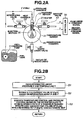
- the fluid-injection control apparatus of the embodiment includes a substantially cylindrical-hollow pressure chamber 10, a heat chamber 20, and an injection section 30.
- a fuel F for an internal combustion engine is used as an example of a fluid to be injected or sprayed.
- Pressure chamber 10 and heat chamber 20 are communicated with each other, and heat chamber 20 and injection section 30 are communicated with each other.
- an observation chamber 40 which communicates the injection section 30, is also provided only for observation of the atomizing state of a fuel spray.
- Fig. 2A an observation chamber 40, which communicates the injection section 30, is also provided only for observation of the atomizing state of a fuel spray.
- the fuel-spray observation system is constructed by a nitrogen introducing valve (a N 2 introducing valve) 41, an exhaust valve 43, and a waste liquid valve 45, in addition to observation chamber 40.
- N 2 introducing valve 41 is provided for introducing nitrogen gas into observation chamber 40.
- Exhaust valve 43 is provided for exhausting the gas from observation chamber 40.
- waste liquid valve 45 is provided for the drainage of waste liquid from observation chamber 40.
- Fuel F stored in a fuel tank is pressurized by a high-pressure pump 11, and then delivered to pressure chamber 10 connected via a pump discharge line to pump 11.
- a pressure sensor 13 is provided and screwed into pressure chamber 10, for detecting a fuel pressure.
- a heater 21 is provided for heating the fluid (fuel F) supplied into heat chamber 20.
- a temperature sensor 31 is installed in injection section 30, for detecting a temperature of the sprayed fluid (the injected fuel F).
- Injection section 30 is constructed by an injection nozzle whose bore diameter is set to a bore size (an inside diameter) of approximately ⁇ 30 ⁇ m, and a valve configured to open or close a nozzle hole of the injection nozzle.
- the injection nozzle and the valve are also configured to achieve the fulfillment of at least the previously-discussed temperature-pressure condition (i) that realizes isobaric specific heat capacity per volume [Cp/V]L of fuel F in the liquid phase and corresponds to a condition at which the fluid has a highest density.
- the valve is constructed by a spring-loaded, fluid-pressure actuated needle valve.
- the valve may be constructed by a piezoelectric-element-actuated valve or an electromagnetically-actuated valve.
- Controller 50 generally comprises a microcomputer. Controller 50 includes an input/output interface (I/O), memories (RAM, ROM), and a microprocessor or a central processing unit (CPU). The input/output interface (I/O) of controller 50 receives at least input information from pressure sensor 13 and temperature sensor 31. Within controller 50, the central processing unit (CPU) allows the access by the I/O interface of input informational data signals from the previously-discussed sensors 13 and 31. The CPU of controller 50 is responsible for carrying a fluid-injection control program (described later in reference to the flowchart shown in Fig. 2B ) stored in memories and is capable of performing necessary arithmetic and logic operations.
- a fluid-injection control program described later in reference to the flowchart shown in Fig. 2B
- Computational results that is, calculated output signals are relayed through the output interface circuitry of the controller to output stages, namely pump 11 and heater 21, for the purpose of pressure control and temperature control for the sprayed fluid (the injected fuel F).
- the controller generates a pump-drive command signal to pump 11 for pressure control for the injected fuel F, and generates a heater-current command signal to heater 21 for temperature control for the injected fuel F.
- controller 50 is configured to control the injection timing (i.e., the opening and closing) of injection section 30.
- Fig. 2B there is shown the control routine executed within controller 50 incorporated in the fluid-injection control apparatus of the embodiment of Fig. 2A .
- the routine shown in Fig. 2B is executed as time-triggered interrupt routines to be triggered every predetermined sampling time intervals.
- step S1 latest up-to-date information about pressure P detected by pressure sensor 13 and temperature T detected by temperature sensor 31, is read.
- step S2 the current value (more recent data) of isobaric specific heat capacity per volume [Cp/V] of the fluid (fuel F), which fluid is subjected to pressure control and temperature control, is estimated based on the detected pressure P and temperature T.
- step S3 temperature control (i.e., heater control) and pressure control (i.e., pump control) are executed based on the estimated isobaric specific heat capacity per volume [Cp/V], in such a manner as to achieve a desired path of a change in isobaric specific heat capacity per volume [Cp/V] of the fluid, while referring to a T-P-[Cp/V] physical-property three-dimensional characteristic diagram (prestored in the controller in the form of a characteristic map) inherent in the use fuel F, and showing the relationship of isobaric specific heat capacity per volume [Cp/V] of the use fuel F with temperature T and pressure P.
- temperature control i.e., heater control
- pressure control i.e., pump control
- the temperature-pressure condition of fuel F is controlled to temperature-pressure condition (i) or controlled via temperature-pressure condition (i) to temperature-pressure condition (iii), through pressure chamber 10 and heat chamber 20.
- the temperature-pressure condition of fuel F is controlled in such a manner as to satisfy temperature-pressure condition (ii), thereby enabling the just-injected fuel having the intermediate isobaric specific heat capacity per volume [Cp/V]J less than [Cp/V]L and greater than [Cp/V]G to be created.
- the fluid-injection control apparatus shown in Figs. 2A-2B is exemplified in a fuel-injection system for an internal combustion engine. It will be appreciated that the fluid-injection control apparatus of the invention is not limited to only the fuel-injection system, but that the fluid-injection control apparatus of the embodiment may be applied to another injection device such as an atomizer or a sprayer.
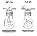
- Fig. 3A shows the compressed self-ignition, direct-injection internal combustion engine employing a fluid-injection control apparatus 1 having almost the same injection control system configuration as Fig. 2A , except a fuel-spray observation system.
- Fig. 3B shows the spark-ignited internal combustion engine employing a fluid-injection control apparatus 1 having almost the same injection control system configuration as Fig. 2A , except a fuel-spray observation system.
- the pressure chamber, the heat chamber, and the injection section are schematically shown.
- fluid-injection control apparatus 1 is arranged substantially at the center of the upper wall of the combustion chamber.
- fluid-injection control apparatus 1 is arranged in the intake-valve port (slightly upstream of the intake valve).
- the use of fluid-injection control apparatus 1 enables optimally-tuned, instantaneous atomization injection (i.e., more finely atomized and more completely gasified fuel). As a result of this, it is possible to effectively suppress formation of particulate matter (PM) such as soot. This contributes to a clean engine and a reduced fuel consumption rate.
- PM particulate matter
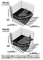
- FIGs. 4A-4D there are shown four T-P-[Cp/V] physical-property three-dimensional characteristic diagrams in the case of four different fuels, namely, normal heptane, butane, hexane, and toluene.
- these fuels have almost the same tendency in their T-P-[Cp/v] physical properties.
- each of the T-P-[Cp/V] physical-property diagrams includes at least four regions, namely, the upper-layer [Cp/V] portion (i.e., temperature-pressure condition (i)) having isobaric specific heat capacity per volume [Cp/V]L, the sloped T-P-[Cp/V] region (i.e., temperature-pressure condition (ii)) having the intermediate isobaric specific heat capacity per volume [Cp/V]J, the raised [Cp/V] portion (i.e., temperature-pressure condition (iii)) having isobaric specific heat capacity per volume [Cp/V] C, and the lower-layer [Cp/V] portion (i.e., temperature-pressure condition (iv)) having isobaric specific heat capacity per volume [Cp/V] G.
- the upper-layer [Cp/V] portion i.e., temperature-pressure condition (i)
- the sloped T-P-[Cp/V] region i
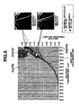
- Fig. 5 there is shown the contour map, obtained by flattening of the T-P-[Cp/V] physical-property three-dimensional characteristic diagram shown in Fig. 4A in the direction of the [Cp/V] axis.
- the injection test has been made at four different temperature-pressure conditions reached just before injecting fluid (normal heptane), and performed according to the following procedures.
- the fluid normal heptane
- the pressurized fluid is supplied from high-pressure pump 11 via the pump discharge line into pressure chamber 10, with injection section 30 kept closed. This results in a fluid pressure rise in pressure chamber 10.
- the fluid pressure in pressure chamber 10 reaches a specified fluid pressure, and then the high-pressure fluid is heated via heat chamber 20 by means of heater 21 energized, until a specified fluid temperature is reached.
- the injection test has been made at four different, specified conditions of temperature and pressure.
- the upper two adjacent plots, each indicated by the voided circle in Fig. 5 exist within the sloped T-P-[Cp/V] region having the intermediate isobaric specific heat capacity per volume [Cp/V]J and extending in close proximity to the high-temperature side of the raised T-P-[Cp/V] region including the critical point.
- the more preferable path (i) ⁇ (ii) ⁇ (iv), as indicated by the arrow (1) in Fig. 1 has been attained by way of injection of the fluid (normal heptane) at each of the two different temperature-pressure conditions respectively corresponding to the upper two adjacent plots.
- the lower plot, indicated by the black dot in Fig. 5 exists on the low-temperature side of the raised T-P- [Cp/V] region including the critical point.
- Injection of the fluid under the temperature-pressure condition corresponding to the lower plot means that the actual temperature-pressure condition of the fluid was unable to exceed the raised T-P-[Cp/V] region (temperature-pressure condition (iii) of isobaric specific heat capacity per volume [Cp/V]C) in spite of temperature control and pressure control executed for satisfying temperature-pressure condition (iii) subsequently to temperature-pressure condition (i) of isobaric specific heat capacity per volume [Cp/V]L, and as a result the fluid injection undesirably occurred at the temperature-pressure condition (i), that is, an undesirable path (i) ⁇ (iii) ⁇ (i) concerning a change in isobaric specific heat capacity per volume [Cp/V] of the fluid.
- the intermediate plot indicated by the voided circle in Fig. 5 and located substantially midway between the lower plot (indicated by the black dot) and the upper two adjacent plots (indicated by the two voided circles), exists within the sloped T-P-[Cp/V] region having the intermediate isobaric specific heat capacity per volume [Cp/V]J but closer to the raised T-P-[Cp/V] region rather than the upper two adjacent plots.
- the preferable path (i) ⁇ (iii) ⁇ (ii) ⁇ (iv) has been attained by way of injection of the fluid (normal heptane) at the temperature-pressure condition corresponding to the intermediate plot.
- controller 50 outputs a trigger signal to injection section 30 so as to shift from its closed state to its fully-open state, and simultaneously outputs a synchronizing signal to a high-speed camera so as to operate the camera synchronously with the injection timing.
- the upper photograph of the right-hand side of Fig. 5 indicates the observed result 1, obtained by injection of the fluid (normal heptane) at each of the three different temperature-pressure conditions respectively corresponding to the upper two adjacent plots and the intermediate plot, all indicated by the voided circles in Fig. 5 .
- the lower photograph of the right-hand side of Fig. 5 indicates the observed result 2, obtained by injection of the fluid (normal heptane) at the temperature-pressure condition corresponding to the lower plot, indicated by the black dot in Fig. 5 .
- the fluid injection method of the embodiment it is possible to achieve a desired path of a change in isobaric specific heat capacity per volume [Cp/V] of a fluid to be injected or sprayed with a liquid-to-gas phase transition by accurately executing temperature control (i.e., heater control) and pressure control (i.e-, pump control) for the fluid, based on the estimated isobaric specific heat capacity per volume [Cp/V], thus realizing fine atomization and complete gasification of the fluid.
- temperature control i.e., heater control
- pressure control i.e-, pump control
Landscapes
- Engineering & Computer Science (AREA)
- Chemical & Material Sciences (AREA)
- Combustion & Propulsion (AREA)
- Mechanical Engineering (AREA)
- General Engineering & Computer Science (AREA)
- Chemical Kinetics & Catalysis (AREA)
- General Chemical & Material Sciences (AREA)
- Oil, Petroleum & Natural Gas (AREA)
- Health & Medical Sciences (AREA)
- Biomedical Technology (AREA)
- Fuel-Injection Apparatus (AREA)
- Nozzles (AREA)
Abstract
Description
- The present invention relates to a method of injecting or spraying fluid, and specifically to the improvement of a technology of injecting fluid in a subcritical state or in a supercritical state near its critical point (its critical temperature and pressure), while gasifying the fluid without including most of the droplets.
- In recent years, there have been proposed and developed various injection technologies of promoting atomization of fluid (e.g., fuel) by injecting or spraying the fluid in a subcritical state or in a supercritical state near its critical point. One such injection technology has been disclosed in Japanese Patent Provisional Publication No.
10-141170 JP10-141170 JP10-141170 - In the case of the injection technology as disclosed in
JP10-141170 - It is, therefore, in view of the previously-described disadvantages of the prior art, an object of the invention to provide a method of injecting fluid, a method of and apparatus for controlling injection of fluid, and an internal combustion engine employing the fluid-injection control apparatus, capable of finely atomizing and sufficiently gasifying the fluid without including most of the droplets, when injecting the fluid with a liquid-to-gas phase transition.
- In order to accomplish the aforementioned and other objects of the present invention, a method of injecting a fluid with a phase transition from a liquid phase to a gaseous phase, the method comprises passing through a temperature-pressure condition (i) that realizes the following equality, as a path of a change in an isobaric specific heat capacity per volume [Cp/V] of the fluid: [Cp/V]-[Cp/V] L, where [Cp/V] L denotes an isobaric specific heat capacity per volume of the fluid in the liquid phase, and passing through a temperature-pressure condition (ii) that realizes the following equality, as the path of the change in the isobaric specific heat capacity per volume [Cp/V] of the fluid: [Cp/V]=[Cp/V]J, where [Cp/V]J denotes an isobaric specific heat capacity per volume of the fluid at timing of injection, which isobaric specific heat capacity per volume [Cp/V] J is less than the isobaric specific heat capacity per volume [Cp/V] L of the fluid in the liquid phase and included in a temperature-pressure region extending in close proximity to a high-temperature side of a temperature-pressure region corresponding to a temperature-pressure condition (iii) that realizes an isobaric specific heat capacity per volume [Cp/V] C of the fluid greater than the isobaric specific heat capacity per volume [Cp/V]L of the fluid in the liquid phase, wherein the fluid is injected via the path leading from the temperature-pressure condition (i) to the temperature-pressure condition (ii) .
- According to another aspect of the invention, a method of controlling injection of a fluid with a phase transition from a liquid phase to a gaseous phase, after having pressurized and heated the fluid through a pressure chamber and a heat chamber, the method comprises detecting a pressure in the pressure chamber, detecting a temperature in the heat chamber, estimating an isobaric specific heat capacity per volume of the fluid, based on both of the detected pressure and the detected temperature, and controlling injection of the fluid, based on the estimated isobaric specific heat capacity per volume.
- According to a further aspect of the invention, an apparatus for injecting a fluid with a phase transition from a liquid phase to a gaseous phase, comprises a pressure chamber provided for pressurizing the fluid, a heat chamber communicating the pressure chamber and provided for heating the fluid, an injection section that injects the fluid, pressurized through the pressure chamber and heated through the heat chamber, a pressure detection section that detects a pressure of the fluid in the pressure chamber, a temperature detection section that detects a temperature of the fluid in the heat chamber, an estimation section that estimates an isobaric specific heat capacity per volume of the fluid, based on both of the detected pressure and the detected temperature, and a control section that controls injection of the fluid, based on the estimated isobaric specific heat capacity per volume of the fluid.
- According to an internal combustion engine comprises an apparatus for injecting a fuel with a phase transition from a liquid phase to a gaseous phase, the apparatus for injecting the fuel comprises a pressure chamber provided for pressurizing the fuel, a heat chamber communicating the pressure chamber and provided for heating the fuel, an injection section that injects the fuel, pressurized through the pressure chamber and heated through the heat chamber, a pressure detection section that detects a pressure of the fuel in the pressure chamber, a temperature detection section that detects a temperature of the fuel in the heat chamber, an estimation section that estimates an isobaric specific heat capacity per volume of the fuel, based on both of the detected pressure and the detected temperature, and a control section that controls injection of the fuel, based on the estimated isobaric specific heat capacity per volume of the fuel.
- The other objects and features of this invention will become understood from the following description with reference to the accompanying drawings.
-
-
Fig. 1 is a T-P-[Cp/V] physical-property three-dimensional characteristic diagram illustrating the relationship among a temperature T, a pressure P, and an isobaric specific heat capacity per volume [Cp/V] of a fluid. -
Fig. 2A is a schematic system diagram illustrating an embodiment of a fluid-injection control apparatus. -
Fig. 2B is a flowchart showing a control routine executed within a controller incorporated in the fluid-injection control apparatus of the embodiment ofFig. 2A . -
Fig. 3A is a side elevational view of a compressed self-ignition, direct-injection internal combustion engine, partly cross-sectioned and installing thereon a fluid-injection control apparatus having almost the same injection control system configuration asFig. 2A , except a fuel-spray observation system. -
Fig. 3B is a side elevational view of a spark-ignited internal combustion engine, partly cross-sectioned and installing thereon a fluid-injection control apparatus having almost the same injection control system configuration asFig. 2A , except a fuel-spray observation system. -
Figs. 4A-4D are T-P-[Cp/V] physical-property three-dimensional characteristic diagrams in the case of four different fuels, namely, normal heptane, butane, hexane, and toluene. -
Fig. 5 is a contour map, obtained by flattening of the T-P-[Cp/v] physical-property three-dimensional characteristic diagram shown inFig. 4A in the direction of the [Cp/V] axis. - Referring now to the drawings, particularly to
Fig. 1 , there is shown the T-P-[Cp/V] physical-property three-dimensional characteristic diagram illustrating the relationship among a temperature T (exactly, a relative temperature against the critical temperature), a pressure P (exactly, a relative pressure against the critical pressure), and an isobaric specific heat capacity per volume [Cp/V] of a fluid (e.g., a fuel such as a normal heptane). As clearly shown inFig. 1 . a change of isobaric specific heat capacity per volume [Cp/V] of this fluid with respect to both of temperature T and pressure P is schematically drawn as a two-layer structure, namely, upper and lower layers. More concretely, the upper-layer portion of isobaric specific heat capacity per volume [Cp/V] of the fluid indicates an isobaric specific heat capacity per volume [Cp/V]L of the fluid conditioned in a liquid phase. Note that isobaric specific heat capacity per volume [Cp/V]L of the fluid conditioned in a liquid phase tends to somewhat fluctuate or vary within a certain range, but not fixed to a constant value, due to various factors, i.e., individual differences of physical properties of fluids of the same sort, and the like. The lower-layer portion of isobaric specific heat capacity per volume [Cp/V] of the fluid indicates an isobaric specific heat capacity per volume [Cp/V]G of the fluid conditioned in a gaseous phase. As can be seen from the T-P-[Cp/V] physical-property characteristic diagram ofFig. 1 , a raised T-P-[Cp/V] region, which includes a critical point (corresponding to a peak value of the isobaric specific heat capacity per volume [Cp/V] of the fluid) and has an isobaric specific heat capacity per volume [Cp/V]C greater than isobaric specific heat capacity per volume [Cp/V]L of the fluid conditioned in the liquid phase, further exists. Additionally, note that a sloped T-P-[Cp/V] region, which extends in close proximity to the high-temperature side of the raised T-P-[Cp/V] region and has an intermediate value [Cp/V]J less than isobaric specific heat capacity per volume [Cp/V]L of the fluid in the liquid phase and greater than isobaric specific heat capacity per volume [Cp/V]G of the fluid in the gaseous phase, further exists. The inventors of this invention have paid their attention to the fact that a temperature rise in the injected or sprayed fluid is disturbed due to a rise in a specific heat capacity of the fluid near its critical point, and thus aimed at a path of a change in isobaric specific heat capacity per volume [Cp/V] of the fluid, as a result of repeated studies. The inventors have discovered that it is possible to optimize atomization of fluid and completely gasify the fluid by controlling the temperature T and pressure P of the fluid in such a manner as to achieve a desired path (hereinafter described in detail) of a change in isobaric specific heat capacity per volume [Cp/V] of the fluid. On the assumption that the previously-described upper-layer [Cp/V] portion is identified as a temperature-pressure condition (i) that realizes isobaric specific heat capacity per volume [Cp/V]L of the fluid in the liquid phase and is defined by the following equality (1), the previously-described sloped [Cp/V] portion is identified as a temperature-pressure condition (ii) that realizes the intermediate isobaric specific heat capacity per volume [Cp/V]J of the fluid and is defined by the following equality (2), the previously-described raised [Cp/V] portion is identified as a temperature-pressure condition (iii) that realizes isobaric specific heat capacity per volume [Cp/V]C greater than isobaric specific heat capacity per volume [Cp/V]L of the fluid in the liquid phase, and the previously-described lower-layer [Cp/V] portion is identified as a temperature-pressure condition (iv) that realizes isobaric specific heat capacity per volume [Cp/V] G of the fluid in the gaseous phase, the desired path of a change in isobaric specific heat capacity per volume [Cp/V] of the fluid to be injected is a path leading from the temperature-pressure condition (i) via the temperature-pressure condition (ii) to the temperature-pressure condition (iv), or a path leading from the temperature-pressure condition (i) via the temperature-pressure condition (iii) and the temperature-pressure condition (ii) to the temperature-pressure condition (iv) in that order.

- In the T-P-[Cp/V] physical-property characteristic diagram of
Fig. 1 , the more preferable path of a change in isobaric specific heat capacity per volume [Cp/V] of the fluid injected or sprayed with a liquid-to-gas phase transition, that is to say, the former path (i) → (ii) → (iv) is indicated by the arrow (1). In the case of the path (i) → (ii) → (iv), indicated by the arrow (1), the high-pressure and high-temperature side of the upper-layer [Cp/V] portion (i.e., temperature-pressure condition (i)) having isobaric specific heat capacity per volume [Cp/V]L and the sloped T-P-[Cp/V] region, extending in close proximity to the high-temperature side of the raised T-P-[Cp/V] region, are utilized, thus easily creating a supercritical-state single phase or a critical-state single phase. As a result of this, it is possible to realize fine atomization and complete gasification of the fluid without including most of the droplets. - on the other hand, in the case of the preferable path concerning a change in isobaric specific heat capacity per volume [Cp/V] of the fluid injected or sprayed with a liquid-to-gas phase transition, that is to say, the previously-discussed path (i) → (iii) → (ii) → (iv), this path must partially pass through the raised T-P-[Cp/V] region including the critical point and having a comparatively greater isobaric specific heat capacity per volume [Cp/V]C. In such a case, a rise in isobaric specific heat capacity (exactly, an isobaric molar specific heat capacity) Cp tends to disturb a temperature rise in the fluid and therefore there is a slight difficulty of realizing the aforementioned temperature-pressure condition (iii).
- In contrast to the above, in the case of three paths concerning a change in isobaric specific heat capacity per volume [Cp/V], indicated by the respective arrows (2), (3), and (4) in
Fig. 1 , a remarkable temperature fall tends to occur during adiabatic expansion of the fluid injected or sprayed with a liquid-to-gas phase transition. This leads to the problem of a phase separation (or a phase segregation) into two phases such as gas-liquid. In such cases, indicated by the arrows (2), (3), and (4), each of which passes through a so-called gas-liquid equilibrium line (see the gas-liquid equilibrium line shown inFig. 5 ), there is an increased tendency for many droplets to be included in the injected fluid flow. - Actually, the previously-discussed path (i) → (ii) → (iv) indicated by the arrow (1) in
Fig. 1 , can be achieved or realized by properly controlling temperature T and pressure P of the injected fluid by means of a fluid-injection control system (described later in reference toFigs. 2A-2B ). For instance, suppose that, under an initial condition of the fluid to be injected or sprayed, temperature T and pressure P of the fluid are a room temperature and a normal pressure (e.g., an atmospheric pressure). The previously-described path (i) → (ii) → (iv). indicated by the arrow (1), can be achieved by pressurizing the fluid up to a pressure level of approximately 110% of its critical pressure at the room temperature and thereafter heating the pressurized fluid up to approximately 105% of its critical temperature. That is, by way of a combination of pressure control and temperature control for a fuel to be injected, it is possible to realize the path passing through the sloped T-P-[Cp/V] region (i.e., temperature-pressure condition (ii)) having the intermediate isobaric specific heat capacity per volume [Cp/V]J, subsequently to the upper-layer [Cp/V] portion (i.e., temperature-pressure condition (i)) having isobaric specific heat capacity per volume [Cp/V]L, while avoiding or bypassing the raised [Cp/V] portion (i.e., temperature-pressure condition (iii)) having isobaric specific heat capacity per volume [Cp/V] C. In other words, the previvusly-discussed desirable path (i) → (ii) → (iv), indicated by the arrow (1) in Fig- 1, can be achieved by properly pressurizing a fluid to be injected or sprayed up to the desired pressure level (e.g., an approximately 110% of its critical pressure) and almost simultaneously heating the pressurized fluid up to the desired temperature value (e.g., an approximately 105% of its critical temperature), such that a liquid-to-gas phase transition of the fluid can be created without passing through the gas-liquid equilibrium line (see the gas-liquid equilibrium line shown inFig. 5 ). - In the fluid injection method of the embodiment, at timing of injection of the fluid, exactly, during a period immediately before injecting the fluid, isobaric specific heat capacity per volume [Cp/V] of the fluid is adjusted to a certain isobaric specific heat capacity per volume [Cp/V]J, which exists within the sloped T-P-[Cp/V] region (corresponding to temperature-pressure condition (ii)) by Way of temperature control and pressure control, for fine atomization and complete gasification of the fluid, and whose magnitude is less than isobaric specific heat capacity per volume [Cp/V]L of the fluid in the liquid phase and greater than isobaric specific heat capacity per volume [Cp/V]G of the fluid in the gaseous phase.
- By satisfying the relationship of the certain isobaric specific heat capacity per volume [Cp/V]J of the fluid at the timing of injection with each of isobaric specific heat capacity per volume [Cp/V]L of the fluid in the liquid phase and isobaric specific heat capacity per volume [Cp/V]G of the fluid in the gaseous phase, which relationship is defined by the following inequality (3), it is possible to effectively sustain an adiabatic expansion of the injected or sprayed and atomizing fluid having the intermediate isobaric specific heat capacity per volume [Cp/V]J at the timing of injection, because of a higher density of the fluid having the intermediate isobaric specific heat capacity per volume [Cp/V]J at the timing of injection in comparison with a density of the fluid having isobaric specific heat capacity per volume [Cp/V]G in the gaseous phase.

- Furthermore, in the fluid injection method of the embodiment, it is more preferable to satisfy the relationship of the certain isobaric specific heat capacity per volume [Cp/V]J of the fluid at the timing of injection with each of isobaric specific heat capacity per volume [Cp/V]L of the fluid in the liquid phase and isobaric specific heat capacity per volume [Cp/V]G of the fluid in the gaseous phase, which relationship is defined by the following inequality (4).

- By satisfying the relationship of the certain isobaric specific heat capacity per volume [Cp/V]J of the fluid at the timing of injection with each of isobaric specific heat capacity per volume [Cp/V]L of the fluid in the liquid phase and isobaric specific heat capacity per volume [Cp/V]G of the fluid in the gaseous phase, which relationship is defined by the above inequality (4), it is possible to reconcile both of a suppression in a rapid drop in isobaric specific heat capacity Cp of the fluid (in other words, a moderate drop in isobaric specific heat capacity Cp or a properly suppressed fluid-temperature fall) and a properly sustained adiabatic expansion of the injected or sprayed and atomizing fluid (in other words, a properly suppressed velocity in adiabatic expansion of the atomizing fluid). Thus, during the adiabatic-expansion process of the injected or sprayed and atomizing fluid, it is possible to effectively avoid an undesirable liquefaction of the fluid occurring due to a temperature fall in the fluid and additionally avoid an undesirably reduced expansibility of the atomizing fluid. It will be appreciated that the fluid injection method of the embodiment can be applied to a fuel injection system of an internal combustion engine. In such a case, according to the fluid injection method of the embodiment, it is possible to avoid an excessive drop in the density of the injected or sprayed fuel, thus preventing an undesirable fall in engine output torque.
- In the fluid injection method of the embodiment discussed in reference to the T-P-[Cp/V] physical-property characteristic diagram shown in
Fig. 1 , a fuel such as a normal heptane is exemplified as a fluid to be injected. It will be understood that the invention is not limited to the particular fluid shown and described herein, but that the fluid injection method of the embodiment may be applied to various fluids, each of which is conditioned in a liquid state at normal pressure and temperature, such as various alcoholic solvents, various hydrocarbon solvents and various fuels for use in a power unit of an internal combustion engine, more concretely, butane, hexane, toluene, gasoline, light oil, heavy oil, and the like. Also, the fluid injection method of the embodiment may be applied to a mixture of at least two fuels, such as a mixture of methanol and gasoline, often called "bio-gasoline fuel", or a fatty acid methyl ether, often called "bio-diesel fuel". - Moreover, the fluid injection method of the embodiment can be suitably applied to fluids each having a physical property that isobaric specific heat capacity per volume [Cp/V]C of the raised [Cp/V] portion (i.e., temperature-pressure condition (iii)) is 1750 J/g·K·m3 or more, for instantaneous atomization injection. As a typical example of such a fluid whose isobaric specific heat capacity per volume [Cp/V]C is greater than or equal to 1750 J/g·K·m3, a motor fuel (a motor spirit or a fuel for an internal combustion engine) is enumerated. By the application of the fluid injection method of the embodiment to such a motor fuel, it is possible to realize instantaneous atomization injection of the motor fuel, thus effectively suppressing formation of particulate matter (PM) such as soot, and also ensuring efficient and good burning of the fuel. This contributes to a clean engine.
- Referring now to
Fig. 2A , there is shown the system diagram of the fluid-injection control apparatus of the embodiment. As seen inFig. 2A , the fluid-injection control apparatus of the embodiment includes a substantially cylindrical-hollow pressure chamber 10, aheat chamber 20, and aninjection section 30. In the system shown inFig. 2A , as an example of a fluid to be injected or sprayed, a fuel F for an internal combustion engine is used.Pressure chamber 10 andheat chamber 20 are communicated with each other, andheat chamber 20 andinjection section 30 are communicated with each other. InFig. 2A , anobservation chamber 40, which communicates theinjection section 30, is also provided only for observation of the atomizing state of a fuel spray. As can be seen inFig. 2A , the fuel-spray observation system is constructed by a nitrogen introducing valve (a N2 introducing valve) 41, anexhaust valve 43, and awaste liquid valve 45, in addition toobservation chamber 40. N2 introducing valve 41 is provided for introducing nitrogen gas intoobservation chamber 40.Exhaust valve 43 is provided for exhausting the gas fromobservation chamber 40. wasteliquid valve 45 is provided for the drainage of waste liquid fromobservation chamber 40. Fuel F stored in a fuel tank is pressurized by a high-pressure pump 11, and then delivered to pressurechamber 10 connected via a pump discharge line to pump 11. A pressure sensor 13 is provided and screwed intopressure chamber 10, for detecting a fuel pressure. Aheater 21 is provided for heating the fluid (fuel F) supplied intoheat chamber 20. Atemperature sensor 31 is installed ininjection section 30, for detecting a temperature of the sprayed fluid (the injected fuel F).Injection section 30 is constructed by an injection nozzle whose bore diameter is set to a bore size (an inside diameter) of approximately φ30µm, and a valve configured to open or close a nozzle hole of the injection nozzle. The injection nozzle and the valve are also configured to achieve the fulfillment of at least the previously-discussed temperature-pressure condition (i) that realizes isobaric specific heat capacity per volume [Cp/V]L of fuel F in the liquid phase and corresponds to a condition at which the fluid has a highest density. In the shown embodiment, the valve is constructed by a spring-loaded, fluid-pressure actuated needle valve. In lieu thereof, the valve may be constructed by a piezoelectric-element-actuated valve or an electromagnetically-actuated valve. - Also provided is a fluid-injection controller (simply, a controller) 50.
Controller 50 generally comprises a microcomputer.Controller 50 includes an input/output interface (I/O), memories (RAM, ROM), and a microprocessor or a central processing unit (CPU). The input/output interface (I/O) ofcontroller 50 receives at least input information from pressure sensor 13 andtemperature sensor 31. Withincontroller 50, the central processing unit (CPU) allows the access by the I/O interface of input informational data signals from the previously-discussedsensors 13 and 31. The CPU ofcontroller 50 is responsible for carrying a fluid-injection control program (described later in reference to the flowchart shown inFig. 2B ) stored in memories and is capable of performing necessary arithmetic and logic operations. Computational results (arithmetic calculation results), that is, calculated output signals are relayed through the output interface circuitry of the controller to output stages, namely pump 11 andheater 21, for the purpose of pressure control and temperature control for the sprayed fluid (the injected fuel F). Concretely, the controller generates a pump-drive command signal to pump 11 for pressure control for the injected fuel F, and generates a heater-current command signal toheater 21 for temperature control for the injected fuel F. In addition, although it is not clearly shown inFig. 2A .controller 50 is configured to control the injection timing (i.e., the opening and closing) ofinjection section 30. - Referring now to
Fig. 2B , there is shown the control routine executed withincontroller 50 incorporated in the fluid-injection control apparatus of the embodiment ofFig. 2A . The routine shown inFig. 2B is executed as time-triggered interrupt routines to be triggered every predetermined sampling time intervals. - At step S1, latest up-to-date information about pressure P detected by pressure sensor 13 and temperature T detected by
temperature sensor 31, is read. - At step S2, the current value (more recent data) of isobaric specific heat capacity per volume [Cp/V] of the fluid (fuel F), which fluid is subjected to pressure control and temperature control, is estimated based on the detected pressure P and temperature T.
- At step S3, temperature control (i.e., heater control) and pressure control (i.e., pump control) are executed based on the estimated isobaric specific heat capacity per volume [Cp/V], in such a manner as to achieve a desired path of a change in isobaric specific heat capacity per volume [Cp/V] of the fluid, while referring to a T-P-[Cp/V] physical-property three-dimensional characteristic diagram (prestored in the controller in the form of a characteristic map) inherent in the use fuel F, and showing the relationship of isobaric specific heat capacity per volume [Cp/V] of the use fuel F with temperature T and pressure P.
- with the previously-discussed arrangement of the fluid-injection control system of the embodiment, first, the temperature-pressure condition of fuel F is controlled to temperature-pressure condition (i) or controlled via temperature-pressure condition (i) to temperature-pressure condition (iii), through
pressure chamber 10 andheat chamber 20. Thereafter, during the period immediately before injecting fuel F frominjection section 30, the temperature-pressure condition of fuel F is controlled in such a manner as to satisfy temperature-pressure condition (ii), thereby enabling the just-injected fuel having the intermediate isobaric specific heat capacity per volume [Cp/V]J less than [Cp/V]L and greater than [Cp/V]G to be created. In this manner, the previously-described more preferable path (i) → (ii) → (iv) or the preferable path (i) → (iii) → (ii) → (iv) can be achieved, thus enabling instantaneous atomization injection. - The fluid-injection control apparatus shown in
Figs. 2A-2B is exemplified in a fuel-injection system for an internal combustion engine. It will be appreciated that the fluid-injection control apparatus of the invention is not limited to only the fuel-injection system, but that the fluid-injection control apparatus of the embodiment may be applied to another injection device such as an atomizer or a sprayer. -
Fig. 3A shows the compressed self-ignition, direct-injection internal combustion engine employing a fluid-injection control apparatus 1 having almost the same injection control system configuration asFig. 2A , except a fuel-spray observation system. On the other hand,Fig. 3B shows the spark-ignited internal combustion engine employing a fluid-injection control apparatus 1 having almost the same injection control system configuration asFig. 2A , except a fuel-spray observation system. For the sake of simplicity, in each ofFigs. 3A-3B , the pressure chamber, the heat chamber, and the injection section are schematically shown. In the compressed self-ignition, direct-injection internal combustion engine shown inFig. 3A , fluid-injection control apparatus 1 is arranged substantially at the center of the upper wall of the combustion chamber. In the spark-ignited internal combustion engine shown inFig. 3B , fluid-injection control apparatus 1 is arranged in the intake-valve port (slightly upstream of the intake valve). The use of fluid-injection control apparatus 1 enables optimally-tuned, instantaneous atomization injection (i.e., more finely atomized and more completely gasified fuel). As a result of this, it is possible to effectively suppress formation of particulate matter (PM) such as soot. This contributes to a clean engine and a reduced fuel consumption rate. - Referring now to
Figs. 4A-4D , there are shown four T-P-[Cp/V] physical-property three-dimensional characteristic diagrams in the case of four different fuels, namely, normal heptane, butane, hexane, and toluene. As can be seen from the four T-P-[Cp/V] physical-property characteristic diagrams for the four different fuels (normal heptane, butane, hexane, and toluene) ofFigs. 4A-4D , basically, these fuels have almost the same tendency in their T-P-[Cp/v] physical properties. That is, each of the T-P-[Cp/V] physical-property diagrams includes at least four regions, namely, the upper-layer [Cp/V] portion (i.e., temperature-pressure condition (i)) having isobaric specific heat capacity per volume [Cp/V]L, the sloped T-P-[Cp/V] region (i.e., temperature-pressure condition (ii)) having the intermediate isobaric specific heat capacity per volume [Cp/V]J, the raised [Cp/V] portion (i.e., temperature-pressure condition (iii)) having isobaric specific heat capacity per volume [Cp/V] C, and the lower-layer [Cp/V] portion (i.e., temperature-pressure condition (iv)) having isobaric specific heat capacity per volume [Cp/V] G. Therefore, it is possible to attain instantaneous atomization injection (in other words, an optimal phase transition from a liquid phase to a gaseous phase with more fine atomization and more complete gasification of the injected fuel), by accurately executing temperature control (i.e., heater control) and pressure control (pump control), both based on the estimated isobaric specific heat capacity per volume [Cp/V], in such a manner as to achieve a desired path (i.e., the path (i) → (ii) → (iv) or the path (i)→(iii)→(ii)→(iv)) of a change in isobaric specific heat capacity per volume [Cp/V] of the fluid. - Referring now to
Fig. 5 , there is shown the contour map, obtained by flattening of the T-P-[Cp/V] physical-property three-dimensional characteristic diagram shown inFig. 4A in the direction of the [Cp/V] axis. As can be seen from four plots inFig. 5 , the injection test has been made at four different temperature-pressure conditions reached just before injecting fluid (normal heptane), and performed according to the following procedures. First, the fluid (normal heptane) is pressurized by high-pressure pump 11. The pressurized fluid is supplied from high-pressure pump 11 via the pump discharge line intopressure chamber 10, withinjection section 30 kept closed. This results in a fluid pressure rise inpressure chamber 10. Thus, the fluid pressure inpressure chamber 10 reaches a specified fluid pressure, and then the high-pressure fluid is heated viaheat chamber 20 by means ofheater 21 energized, until a specified fluid temperature is reached. In this manner, the injection test has been made at four different, specified conditions of temperature and pressure. The upper two adjacent plots, each indicated by the voided circle inFig. 5 , exist within the sloped T-P-[Cp/V] region having the intermediate isobaric specific heat capacity per volume [Cp/V]J and extending in close proximity to the high-temperature side of the raised T-P-[Cp/V] region including the critical point. In other words, the more preferable path (i) → (ii) → (iv), as indicated by the arrow (1) inFig. 1 , has been attained by way of injection of the fluid (normal heptane) at each of the two different temperature-pressure conditions respectively corresponding to the upper two adjacent plots. In contrast, the lower plot, indicated by the black dot inFig. 5 , exists on the low-temperature side of the raised T-P- [Cp/V] region including the critical point. Injection of the fluid under the temperature-pressure condition corresponding to the lower plot, means that the actual temperature-pressure condition of the fluid was unable to exceed the raised T-P-[Cp/V] region (temperature-pressure condition (iii) of isobaric specific heat capacity per volume [Cp/V]C) in spite of temperature control and pressure control executed for satisfying temperature-pressure condition (iii) subsequently to temperature-pressure condition (i) of isobaric specific heat capacity per volume [Cp/V]L, and as a result the fluid injection undesirably occurred at the temperature-pressure condition (i), that is, an undesirable path (i) → (iii) → (i) concerning a change in isobaric specific heat capacity per volume [Cp/V] of the fluid. On the other hand, the intermediate plot, indicated by the voided circle inFig. 5 and located substantially midway between the lower plot (indicated by the black dot) and the upper two adjacent plots (indicated by the two voided circles), exists within the sloped T-P-[Cp/V] region having the intermediate isobaric specific heat capacity per volume [Cp/V]J but closer to the raised T-P-[Cp/V] region rather than the upper two adjacent plots. In other words, the preferable path (i) → (iii) → (ii) → (iv) has been attained by way of injection of the fluid (normal heptane) at the temperature-pressure condition corresponding to the intermediate plot. As soon as each of the four different, specified conditions of temperature and pressure has been reached,controller 50 outputs a trigger signal toinjection section 30 so as to shift from its closed state to its fully-open state, and simultaneously outputs a synchronizing signal to a high-speed camera so as to operate the camera synchronously with the injection timing. The upper photograph of the right-hand side ofFig. 5 indicates the observedresult 1, obtained by injection of the fluid (normal heptane) at each of the three different temperature-pressure conditions respectively corresponding to the upper two adjacent plots and the intermediate plot, all indicated by the voided circles inFig. 5 . In contrast, the lower photograph of the right-hand side ofFig. 5 indicates the observedresult 2, obtained by injection of the fluid (normal heptane) at the temperature-pressure condition corresponding to the lower plot, indicated by the black dot inFig. 5 . - As can be seen from the observed result 1 (i.e., the upper photograph of the right-hand side of
Fig. 5 ), in the case of injection of the fluid (normal heptane) at each of the three different temperature-pressure conditions respectively corresponding to the upper two adjacent plots and the intermediate plot, in other words, in the case of the desired path {the path (i) → (ii) → (iv) (see the arrow (1) shown inFig. 1 ) or the path (i) → (iii) → (ii) →(iv) } of a change in isobaric specific heat capacity per volume [Cp/V] of the fluid, by virtue of the synergistic effect of a properly suppressed drop in isobaric specific heat capacity Cp of the fluid (in other words, a properly suppressed fluid-temperature fall) and a properly sustained adiabatic expansion of the injected or sprayed and atomizing fluid (in other words, a properly suppressed velocity in adiabatic expansion of the atomizing fluid), there are less droplets, observed by way of visual observation. That is, injecting the fluid (normal heptane) at each of the three different temperature-pressure conditions respectively corresponding to the upper two adjacent plots and the intermediate plot realizes invisible high-speed jet flow (or invisible high-speed instantaneous atomization fluid injection). - In contrast, as can be seen from the observed result 2 (i.e., the lower photograph of the right-hand side of
Fig. 5 ), in the case of injection of the fluid (normal heptane) at the temperature-pressure condition corresponding to the lower plot, in other words, in the case of the undesirable path (i.e., the path (i) → (iii) → (i)) of a change in isobaric specific heat capacity per volume [Cp/V] of the fluid, there are many droplets (in other words, short visible jet flow), observed by way of visual observation. - As will be appreciated from the above, according to the fluid injection method of the embodiment, it is possible to achieve a desired path of a change in isobaric specific heat capacity per volume [Cp/V] of a fluid to be injected or sprayed with a liquid-to-gas phase transition by accurately executing temperature control (i.e., heater control) and pressure control (i.e-, pump control) for the fluid, based on the estimated isobaric specific heat capacity per volume [Cp/V], thus realizing fine atomization and complete gasification of the fluid.
- The entire contents of Japanese Patent Application No.
2007-168479 (filed June 27, 2007 - While the foregoing is a description of the preferred embodiments carried out the invention, it will be understood that the invention is not limited to the particular embodiments shown and described herein, but that various changes and modifications may be made without departing from the scope or spirit of this invention as defined by the following claims.
Claims (26)
- A method of injecting a fluid with a phase transition from a liquid phase to a gaseous phase, the method comprising:passing through a temperature-pressure condition (i) that realizes the following equality, as a path of a change in an isobaric specific heat capacity per volume [Cp/V] of the fluid:

where [Cp/V]L denotes an isobaric specific heat capacity per volume of the fluid in the liquid phase; andpassing through a temperature-pressure condition (ii) that realizes the following equality, as the path of the change in the isobaric specific heat capacity per volume [Cp/V] of the fluid:wherein the fluid is injected via the path leading from the temperature-pressure condition (i) to the temperature-pressure condition (ii).
where [Cp/V]J denotes an isobaric specific heat capacity per volume of the fluid at timing of injection, which isobaric specific heat capacity per volume [Cp/V]J is less than the isobaric specific heat capacity per volume [Cp/V]L of the fluid in the liquid phase and included in a temperature-pressure region extending in close proximity to a high-temperature side of a temperature-pressure region corresponding to a temperature-pressure condition (iii) that realizes an isobaric specific heat capacity per volume [Cp/V]C of the fluid greater than the isobaric specific heat capacity per volume [Cp/V]L of the fluid in the liquid phase, - The method as claimed in claim 1, wherein:the path leading from the temperature-pressure condition (i) to the temperature-pressure condition (ii) is either one of a path (i) → (ii) leading to the temperature-pressure condition (ii) subsequently to the temperature-pressure condition (i) and a path (i) → (iii) → (ii) leading from the temperature-pressure condition (i) via the temperature-pressure condition (iii) to the temperature-pressure condition (ii) .
- The method as claimed in claim 2, wherein:assuming that [Cp/V]G denotes an isobaric specific heat capacity per volume of the fluid in the gaseous phase, a relationship of the isobaric specific heat capacity per volume [Cp/V]J of the fluid at the timing of injection with each of the isobaric specific heat capacity per volume [Cp/V]L of the fluid in the liquid phase and the isobaric specific heat capacity per volume [Cp/V]G of the fluid in the gaseous phase, satisfies a relation defined by the following inequality:

- The method as claimed in claim 3, wherein:the relationship of the isobaric specific heat capacity per volume [Cp/V]J of the fluid at the timing of injection with each of the isobaric specific heat capacity per volume [Cp/V]L of the fluid in the liquid phase and the isobaric specific heat capacity per volume [Cp/V]G of the fluid in the gaseous phase, further satisfies a relation defined by the following inequality:

- The method as claimed in claim 1, wherein:the fluid is a fuel (F) for an internal combustion engine.
- A method of controlling injection of a fluid with a phase transition from a liquid phase to a gaseous phase, after having pressurized and heated the fluid through a pressure chamber (10) and a heat chamber (20), the method comprising:detecting a pressure (P) in the pressure chamber (10);detecting a temperature (T) in the heat chamber (20);estimating an isobaric specific heat capacity per volume of the fluid, based on both of the detected pressure (P) and the detected temperature (T); andcontrolling injection of the fluid, based on the estimated isobaric specific heat capacity per volume.
- The method of controlling injection as claimed in claim 6, wherein:the pressure (P) of the fluid in the pressure chamber (10) and the temperature (T) of the fluid in the heat chamber (20) are controlled based on the estimated isobaric specific heat capacity per volume, when injecting the fluid with the phase transition from the liquid phase to the gaseous phase, for bringing a desired path of a change in an isobaric specific heat capacity per volume [Cp/V] of the fluid, the desired path comprising:wherein the fluid is injected via the desired path leading from the temperature-pressure condition (i) to the temperature-pressure condition (ii).passing through a temperature-pressure condition (i) that realizes the following equality:

where [Cp/V] L denotes an isobaric specific heat capacity per volume of the fluid in the liquid phase; andpassing through a temperature-pressure condition (ii) that realizes the following equality:
where [Cp/V]J denotes an isobaric specific heat capacity per volume of the fluid at timing of injection, which isobaric specific heat capacity per volume [Cp/V]J is less than the isobaric specific heat capacity per volume [Cp/V]L of the fluid in the liquid phase and included in a temperature-pressure region extending in close proximity to a high-temperature side of a temperature-pressure region corresponding to a temperature-pressure condition (iii) that realizes an isobaric specific heat capacity per volume [Cp/V]C of the fluid greater than the isobaric specific heat capacity per volume [Cp/V]L of the fluid in the liquid phase, - The method of controlling injection as claimed in claim 7, wherein:the desired path leading from the temperature-pressure condition (i) to the temperature-pressure condition (ii) is either one of a path (i) → (ii) leading to the temperature-pressure condition (ii) subsequently to the temperature-pressure condition (i) and a path (i) → (iii) → (ii) leading from the temperature-pressure condition (i) via the temperature-pressure condition (iii) to the temperature-pressure condition (ii).
- The method of controlling injection as claimed in claim 8, wherein:assuming that [Cp/V]G denotes an isobaric specific heat capacity per volume of the fluid in the gaseous phase, a relationship of the isobaric specific heat capacity per volume [Cp/V]J of the fluid at the timing of injection with each of the isobaric specific heat capacity per volume [Cp/V]L of the fluid in the liquid phase and the isobaric specific heat capacity per volume [Cp/V]G of the fluid in the gaseous phase, satisfies a relation defined by the following inequality:

- The method of controlling injection as claimed in claim 9, wherein:the relationship of the isobaric specific heat capacity per volume [Cp/V]J of the fluid at the timing of injection with each of the isobaric specific heat capacity per volume [Cp/V]L of the fluid in the liquid phase and the isobaric specific heat capacity per volume [Cp/V]G of the fluid in the gaseous phase, further satisfies a relation defined by the following inequality:

- The method of controlling injection as claimed in claim 6, wherein:the fluid is a fuel (F) for an internal combustion engine.
- An apparatus for injecting a fluid with a phase transition from a liquid phase to a gaseous phase, comprising:a pressure chamber (10) provided for pressurizing the fluid;a heat chamber (20) communicating the pressure chamber (10) and provided for heating the fluid;an injection section (30) that injects the fluid, pressurized through the pressure chamber (10) and heated through the heat chamber (20);a pressure detection section (13) that detects a pressure (P) of the fluid in the pressure chamber (10);a temperature detection section (31) that detects a temperature (T) of the fluid in the heat chamber (20);an estimation section (50) that estimates an isobaric specific heat capacity per volume of the fluid, based on both of the detected pressure (P) and the detected temperature (T); anda control section (50) that controls injection of the fluid, based on the estimated isobaric specific heat capacity per volume of the fluid.
- The apparatus for controlling injection as claimed in claim 12, wherein:the control section (50) controls, based on the estimated isobaric specific heat capacity per volume, the pressure (P) of the fluid in the pressure chamber (10) and the temperature (T) of the fluid in the heat chamber (20), for bringing a desired path of a change in an isobaric specific heat capacity per volume [Cp/V] of the fluid, when injecting the fluid with the phase transition from the liquid phase to the gaseous phase, the desired path comprising:wherein the fluid is injected via the desired path leading from the temperature-pressure condition (i) to the temperature-pressure condition (ii).passing through a temperature-pressure condition (i) that realizes the following equality:

where [Cp/v]L denotes an isobaric specific heat capacity per volume of the fluid in the liquid phase; andpassing through a temperature-pressure condition (ii) that realizes the following equality:
where [Cp/V]J denotes an isobaric specific heat capacity per volume of the fluid at timing of injection, which isobaric specific heat capacity per volume [Cp/V]J is less than the isobaric specific heat capacity per volume [Cp/V]L of the fluid in the liquid phase and included in a temperature-pressure region extending in close proximity to a high-temperature side of a temperature-pressure region corresponding to a temperature-pressure condition (iii) that realizes an isobaric specific heat capacity per volume [Cp/V]C of the fluid greater than the isobaric specific heat capacity per volume [Cp/V]L of the fluid in the liquid phase - The apparatus for controlling injection as claimed in claim 13, wherein:the desired path leading from the temperature-pressure condition (i) to the temperature-pressure condition (ii) is either one of a path (i) → (ii) leading to the temperature-pressure condition (ii) subsequently to the temperature-pressure condition (i) and a path (i)→(iii)→(ii) leading from the temperature-pressure condition (i) via the temperature-pressure condition (iii) to the temperature-pressure condition (ii).
- The apparatus for controlling injection as claimed in claim 14, wherein:assuming that [Cp/V]G denotes an isobaric specific heat capacity per volume of the fluid in the gaseous phase, a relationship of the isobaric specific heat capacity per volume [Cp/V]J of the fluid at the timing of injection with each of the isobaric specific heat capacity per volume [Cp/V]L of the fluid in the liquid phase and the isobaric specific heat capacity per volume [Cp/V]G of the fluid in the gaseous phase, satisfies a relation defined by the following inequality:

- The apparatus for controlling injection as claimed in claim 15, wherein:the relationship of the isobaric specific heat capacity per volume [Cp/V]J of the fluid at the timing of injection with each of the isobaric specific heat capacity per volume [Cp/V] L of the fluid in the liquid phase and the isobaric specific heat capacity per volume [Cp/V]G of the fluid in the gaseous phase, further satisfies a relation defined by the following inequality:

- The apparatus for controlling injection as claimed in claim 12, wherein:the fluid is a fuel (F) for an internal combustion engine.
- The apparatus for controlling injection as claimed in claim 12, wherein:the injection section (30) comprises:wherein the injection nozzle and the valve are configured to achieve a fulfillment of at least the temperature-pressure condition (i) that realizes the equalityan injection nozzle whose bore diameter is set to a predetermined bore size; anda valve configured to open or close a nozzle hole of the injection nozzle,

- The apparatus for controlling injection as claimed in claim 12, further comprising:a pump (11) configured to pressurize the fluid and to supply the pressurized fluid into the pressure chamber (10).
- An internal combustion engine comprising:an apparatus for injecting a fuel (F) with a phase transition from a liquid phase to a gaseous phase, the apparatus for injecting the fuel (F) comprising:(a) a pressure chamber (10) provided for pressurizing the fuel (F);(b) a heat chamber (20) communicating the pressure chamber (10) and provided for heating the fuel (F);(c) an injection section (30) that injects the fuel (F), pressurized through the pressure chamber (10) and heated through the heat chamber (20);(d) a pressure detection section (13) that detects a pressure (P) of the fuel (F) in the pressure chamber (10);(e) a temperature detection section (31) that detects a temperature (T) of the fuel (F) in the heat chamber (20);(f) an estimation section (50) that estimates an isobaric specific heat capacity per volume of the fuel (F), based on both of the detected pressure (P) and the detected temperature (T); and(g) a control section (50) that controls injection of the fuel (F), based on the estimated isobaric specific heat capacity per volume of the fuel (F).
- The internal combustion engine as claimed in claim 20, wherein:the control section (50) controls, based on the estimated isobaric specific heat capacity per volume, the pressure (P) of the fuel (F) in the pressure chamber (10) and the temperature (T) of the fuel (F) in the heat chamber (20), for bringing a desired path of a change in an isobaric specific heat capacity per volume [Cp/V] of the fuel (F), when injecting the fuel (F) with the phase transition from the liquid phase to the gaseous phase, the desired path comprising:passing through a temperature-pressure condition (i) that realizes the following equality:

where [Cp/V]L denotes an isobaric specific heat capacity per volume of the fuel (F) in the liquid phase; andpassing through a temperature-pressure condition (ii) that realizes the following equality:wherein the fuel (F) is injected via the desired path leading from the temperature-pressure condition (i) to the temperature-pressure condition (ii).
where [Cp/V]J denotes an isobaric specific heat capacity per volume of the fuel (F) at timing of injection, which isobaric specific heat capacity per volume [Cp/V]J is less than the isobaric specific heat capacity per volume [Cp/V]L of the fuel (F) in the liquid phase and included in a temperature-pressure region extending in close proximity to a high-temperature side of a temperature-pressure region corresponding to a temperature-pressure condition (iii) that realizes an isobaric specific heat capacity per volume [Cp/V] C of the fuel (F) greater than the isobaric specific heat capacity per volume [Cp/V] L of the fuel (F) in the liquid phase, - The internal combustion engine as claimed in claim 21, wherein:the desired path leading from the temperature-pressure condition (i) to the temperature-pressure condition (ii) is either one of a path (i) → (ii) leading to the temperature-pressure condition (ii) subsequently to the temperature-pressure condition (i) and a path (i) → (iii) → (ii) leading from the temperature-pressure condition (i) via the temperature-pressure condition (iii) to the temperature-pressure condition (ii).
- The internal combustion engine as claimed in claim 22, wherein:assuming that [Cp/V]G denotes an isobaric specific heat capacity per volume of the fuel (F) in the gaseous phase, a relationship of the isobaric specific heat capacity per volume [Cp/V]J of the fuel (F) at the timing of injection with each of the isobaric specific heat capacity per volume [Cp/V]L of the fuel (F) in the liquid phase and the isobaric specific heat capacity per volume [Cp/V]G of the fuel (F) in the gaseous phase, satisfies a relation defined by the following inequality:

- The internal combustion engine as claimed in claim 23, wherein:the relationship of the isobaric specific heat capacity per volume [Cp/V] J of the fuel (F) at the timing of injection with each of the isobaric specific heat capacity per volume [Cp/V]L of the fuel (F) in the liquid phase and the isobaric specific heat capacity per volume [Cp/V]G of the fuel (F) in the gaseous phase, further satisfies a relation defined by the following inequality:

- The internal combustion engine as claimed in claim 20, wherein:the injection section (30) comprises:wherein the injection nozzle and the valve are configured to achieve a fulfillment of at least the temperature-pressure condition (i) that realizes the equality [Cp/V] = [Cp/V]L.an injection nozzle whose bore diameter is set to a predetermined bore size; anda valve configured to open or close a nozzle hole of the injection nozzle,
- The internal combustion engine as claimed in claim 20, further comprising:a pump (11) configured to pressurize the fuel (F) and to supply the pressurized fuel (F) into the pressure chamber (10).
Applications Claiming Priority (1)
| Application Number | Priority Date | Filing Date | Title |
|---|---|---|---|
| JP2007168479 | 2007-06-27 |
Publications (2)
| Publication Number | Publication Date |
|---|---|
| EP2009266A2 true EP2009266A2 (en) | 2008-12-31 |
| EP2009266A3 EP2009266A3 (en) | 2010-08-25 |
Family
ID=39719097
Family Applications (1)
| Application Number | Title | Priority Date | Filing Date |
|---|---|---|---|
| EP08011530A Withdrawn EP2009266A3 (en) | 2007-06-27 | 2008-06-25 | A method of injecting fluid, a method of and apparatus for controlling injection of fluid, and an internal combustion engine |
Country Status (3)
| Country | Link |
|---|---|
| US (1) | US20090037076A1 (en) |
| EP (1) | EP2009266A3 (en) |
| JP (1) | JP2009030596A (en) |
Cited By (2)
| Publication number | Priority date | Publication date | Assignee | Title |
|---|---|---|---|---|
| EP2385240A1 (en) * | 2010-05-04 | 2011-11-09 | Delphi Technologies, Inc. | Heated fuel injector system |
| EP2764230A4 (en) * | 2011-10-05 | 2016-05-11 | Westport Power Inc | MODULE FOR MANAGING MASS FLOW AND DAMPING PRESSURE PULSATIONS IN A GAS FUEL SUPPLY PIPE |
Families Citing this family (3)
| Publication number | Priority date | Publication date | Assignee | Title |
|---|---|---|---|---|
| JP5580781B2 (en) * | 2011-05-20 | 2014-08-27 | 株式会社日本自動車部品総合研究所 | Fuel supply device |
| US9702307B2 (en) * | 2013-09-05 | 2017-07-11 | Ford Global Technologies, Llc | Method for controlling fuel pressure for a LPG engine |
| BR102020026406A2 (en) * | 2020-12-22 | 2022-07-05 | Robert Bosch Limitada | FUEL HEATING DEVICE |
Citations (2)
| Publication number | Priority date | Publication date | Assignee | Title |
|---|---|---|---|---|
| JPH10141170A (en) | 1996-11-14 | 1998-05-26 | Toyota Motor Corp | High temperature and high pressure injector |
| JP2007168479A (en) | 2005-12-19 | 2007-07-05 | Toyota Motor Corp | Vehicle side structure |
Family Cites Families (5)
| Publication number | Priority date | Publication date | Assignee | Title |
|---|---|---|---|---|
| DE2800894C2 (en) * | 1978-01-10 | 1984-01-19 | Max Planck Gesellschaft zur Förderung der Wissenschaften e.V., 3400 Göttingen | Process for converting a liquid fuel consisting of a retrograde substance into the gaseous state |
| US6332457B1 (en) * | 1999-02-26 | 2001-12-25 | Siemens Automotive Corporation | Method of using an internally heated tip injector to reduce hydrocarbon emissions during cold-start |
| US6827047B2 (en) * | 2001-12-19 | 2004-12-07 | Honda Giken Kogyo Kabushiki Kaisha | Vehicle provided with internal combustion engine and fuel reforming/supplying functions |
| US6868839B2 (en) * | 2003-04-10 | 2005-03-22 | Alex Chu | Vaporized fuel injection system and method |
| EP1602814A3 (en) * | 2004-06-04 | 2012-05-23 | Nissan Motor Co., Ltd. | Engine control device and control method |
-
2008
- 2008-06-25 US US12/145,967 patent/US20090037076A1/en not_active Abandoned
- 2008-06-25 EP EP08011530A patent/EP2009266A3/en not_active Withdrawn
- 2008-06-27 JP JP2008168308A patent/JP2009030596A/en active Pending
Patent Citations (2)
| Publication number | Priority date | Publication date | Assignee | Title |
|---|---|---|---|---|
| JPH10141170A (en) | 1996-11-14 | 1998-05-26 | Toyota Motor Corp | High temperature and high pressure injector |
| JP2007168479A (en) | 2005-12-19 | 2007-07-05 | Toyota Motor Corp | Vehicle side structure |
Cited By (3)
| Publication number | Priority date | Publication date | Assignee | Title |
|---|---|---|---|---|
| EP2385240A1 (en) * | 2010-05-04 | 2011-11-09 | Delphi Technologies, Inc. | Heated fuel injector system |
| EP2764230A4 (en) * | 2011-10-05 | 2016-05-11 | Westport Power Inc | MODULE FOR MANAGING MASS FLOW AND DAMPING PRESSURE PULSATIONS IN A GAS FUEL SUPPLY PIPE |
| US9429094B2 (en) | 2011-10-05 | 2016-08-30 | Westport Power Inc. | Module for managing mass flow and dampening pressure pulsations in a gaseous fuel supply line |
Also Published As
| Publication number | Publication date |
|---|---|
| US20090037076A1 (en) | 2009-02-05 |
| JP2009030596A (en) | 2009-02-12 |
| EP2009266A3 (en) | 2010-08-25 |
Similar Documents
| Publication | Publication Date | Title |
|---|---|---|
| US6467466B1 (en) | Gas leakage detection and fail-safe control method for gas-fueled internal combustion engine and apparatus for implementing the same | |
| CN104066960B (en) | A kind of device and method to flexible fuel internal combustion engine addition fuel | |
| US7627416B2 (en) | Method and apparatus for operating a dual fuel internal combustion engine | |
| US9234452B2 (en) | Direct injection gas engine and method | |
| RU2638491C2 (en) | Fuel system for gaseous fuel engine and method of adjusting pressure of gaseous fuel | |
| CN100365258C (en) | fuel delivery system | |
| US20090037076A1 (en) | Method of injecting fluid, a method of and apparatus for controlling injection of fluid, and an internal combustion engine | |
| US6205981B1 (en) | Fuel recirculation for direct injection fuel system using a high pressure variable venturi pump | |
| US9765717B2 (en) | Gaseous fuel conversion system for marine vessels, and related accessories | |
| CN100453784C (en) | How to operate a gas engine | |
| US7506638B2 (en) | Fuel delivery system | |
| EP2199656A1 (en) | Liquefied petroleum gas tank for a vehicle, and fuel supply system including said tank | |
| JPH11107871A (en) | Diesel engine fuel system using dimethyl ether fuel | |
| EP3330518B1 (en) | A fuel valve for injecting gaseous fuel into a combustion chamber of a large two-stroke turbocharged compression-ignition internal combustion engine and method | |
| JP4670588B2 (en) | Diesel engine fueled with dimethyl ether | |
| KR101004331B1 (en) | Fuel supply device for liquefied gas internal combustion engine | |
| CN208845275U (en) | The double common rail hydraulic injection devices of use for diesel engine can be changed injection rate spraying system | |
| KR20120090209A (en) | Apparatus and method for controlling fuel feed of automobile using both gasoline and lpg | |
| GB2540532A (en) | Injector | |
| KR20020092051A (en) | The Injection System of Liquefied Petroleum Gas | |
| JP3818634B2 (en) | LPG engine fuel supply system | |
| JP2000320405A (en) | Fuel supply device of lpg engine | |
| WO2025075837A1 (en) | Fuel system that prevents vapor lock in powertrains converted to run on a volatile alternative fuel | |
| JP6164601B2 (en) | FUEL INJECTION CONNECTION DEVICE CAPABLE OF MULTI-FUEL FUEL, FUEL INJECTION SYSTEM USING THE CONNECTION DEVICE, AND CONNECTION METHOD USING THE CONNECTION DEVICE | |
| AU2005211674A1 (en) | Fuel delivery system |
Legal Events
| Date | Code | Title | Description |
|---|---|---|---|
| PUAI | Public reference made under article 153(3) epc to a published international application that has entered the european phase |
Free format text: ORIGINAL CODE: 0009012 |
|
| 17P | Request for examination filed |
Effective date: 20080625 |
|
| AK | Designated contracting states |
Kind code of ref document: A2 Designated state(s): AT BE BG CH CY CZ DE DK EE ES FI FR GB GR HR HU IE IS IT LI LT LU LV MC MT NL NO PL PT RO SE SI SK TR |
|
| AX | Request for extension of the european patent |
Extension state: AL BA MK RS |
|
| PUAL | Search report despatched |
Free format text: ORIGINAL CODE: 0009013 |
|
| AK | Designated contracting states |
Kind code of ref document: A3 Designated state(s): AT BE BG CH CY CZ DE DK EE ES FI FR GB GR HR HU IE IS IT LI LT LU LV MC MT NL NO PL PT RO SE SI SK TR |
|
| AX | Request for extension of the european patent |
Extension state: AL BA MK RS |
|
| STAA | Information on the status of an ep patent application or granted ep patent |
Free format text: STATUS: THE APPLICATION HAS BEEN WITHDRAWN |
|
| 18W | Application withdrawn |
Effective date: 20101229 |