EP2008057B1 - Method of measuring a clearance of a hub bearing for vehicles - Google Patents
Method of measuring a clearance of a hub bearing for vehicles Download PDFInfo
- Publication number
- EP2008057B1 EP2008057B1 EP07746752.0A EP07746752A EP2008057B1 EP 2008057 B1 EP2008057 B1 EP 2008057B1 EP 07746752 A EP07746752 A EP 07746752A EP 2008057 B1 EP2008057 B1 EP 2008057B1
- Authority
- EP
- European Patent Office
- Prior art keywords
- inner ring
- hub
- measuring
- clearance
- press
- Prior art date
- Legal status (The legal status is an assumption and is not a legal conclusion. Google has not performed a legal analysis and makes no representation as to the accuracy of the status listed.)
- Not-in-force
Links
- 238000000034 method Methods 0.000 title claims description 35
- 238000006073 displacement reaction Methods 0.000 claims description 18
- 238000005259 measurement Methods 0.000 description 6
- 230000036316 preload Effects 0.000 description 2
- 230000005489 elastic deformation Effects 0.000 description 1
- 238000004519 manufacturing process Methods 0.000 description 1
Images




Classifications
-
- G—PHYSICS
- G01—MEASURING; TESTING
- G01B—MEASURING LENGTH, THICKNESS OR SIMILAR LINEAR DIMENSIONS; MEASURING ANGLES; MEASURING AREAS; MEASURING IRREGULARITIES OF SURFACES OR CONTOURS
- G01B5/00—Measuring arrangements characterised by the use of mechanical techniques
- G01B5/30—Measuring arrangements characterised by the use of mechanical techniques for measuring the deformation in a solid, e.g. mechanical strain gauge
-
- G—PHYSICS
- G01—MEASURING; TESTING
- G01B—MEASURING LENGTH, THICKNESS OR SIMILAR LINEAR DIMENSIONS; MEASURING ANGLES; MEASURING AREAS; MEASURING IRREGULARITIES OF SURFACES OR CONTOURS
- G01B5/00—Measuring arrangements characterised by the use of mechanical techniques
- G01B5/14—Measuring arrangements characterised by the use of mechanical techniques for measuring distance or clearance between spaced objects or spaced apertures
- G01B5/146—Measuring arrangements characterised by the use of mechanical techniques for measuring distance or clearance between spaced objects or spaced apertures measuring play on bearings
-
- G—PHYSICS
- G01—MEASURING; TESTING
- G01B—MEASURING LENGTH, THICKNESS OR SIMILAR LINEAR DIMENSIONS; MEASURING ANGLES; MEASURING AREAS; MEASURING IRREGULARITIES OF SURFACES OR CONTOURS
- G01B21/00—Measuring arrangements or details thereof, where the measuring technique is not covered by the other groups of this subclass, unspecified or not relevant
- G01B21/16—Measuring arrangements or details thereof, where the measuring technique is not covered by the other groups of this subclass, unspecified or not relevant for measuring distance of clearance between spaced objects
-
- G—PHYSICS
- G01—MEASURING; TESTING
- G01B—MEASURING LENGTH, THICKNESS OR SIMILAR LINEAR DIMENSIONS; MEASURING ANGLES; MEASURING AREAS; MEASURING IRREGULARITIES OF SURFACES OR CONTOURS
- G01B5/00—Measuring arrangements characterised by the use of mechanical techniques
-
- F—MECHANICAL ENGINEERING; LIGHTING; HEATING; WEAPONS; BLASTING
- F16—ENGINEERING ELEMENTS AND UNITS; GENERAL MEASURES FOR PRODUCING AND MAINTAINING EFFECTIVE FUNCTIONING OF MACHINES OR INSTALLATIONS; THERMAL INSULATION IN GENERAL
- F16C—SHAFTS; FLEXIBLE SHAFTS; ELEMENTS OR CRANKSHAFT MECHANISMS; ROTARY BODIES OTHER THAN GEARING ELEMENTS; BEARINGS
- F16C2229/00—Setting preload
-
- Y—GENERAL TAGGING OF NEW TECHNOLOGICAL DEVELOPMENTS; GENERAL TAGGING OF CROSS-SECTIONAL TECHNOLOGIES SPANNING OVER SEVERAL SECTIONS OF THE IPC; TECHNICAL SUBJECTS COVERED BY FORMER USPC CROSS-REFERENCE ART COLLECTIONS [XRACs] AND DIGESTS
- Y10—TECHNICAL SUBJECTS COVERED BY FORMER USPC
- Y10T—TECHNICAL SUBJECTS COVERED BY FORMER US CLASSIFICATION
- Y10T29/00—Metal working
- Y10T29/49—Method of mechanical manufacture
- Y10T29/49636—Process for making bearing or component thereof
- Y10T29/497—Pre-usage process, e.g., preloading, aligning
Definitions
- the present invention relates to a method of measuring a clearance of a hub bearing for vehicles, and more particularly to a method of measuring a clearance of a hub bearing for vehicles, wherein an amount of a clearance known to have a great influence on a bearing life can be simply measured compared to a prior art measuring method. Specifically, this is performed by fixing a hub in the state where a row of hub-side balls is disposed and an outer ring is disposed on an outer periphery of the hub and press-fitting an inner ring by means of a press-fit jig and measuring an amount of press-fitting the inner ring from when a gauge installed to a portion of the outer ring begins to move when press-fitting the inner ring is completed.
- a hub bearing unit which is mounted to an axle of the vehicle, supports a body of a vehicle. Since balls rotate in the hub bearing, the axle of the vehicle is allowed for smooth rotation. A clearance of the bearing has a great influence on the life of the bearing.
- the hub bearing unit which is used for an axle of a vehicle, is consisted of a hub 1, balls 2, an inner ring 3, an outer ring 4, a retainer, hub-bolts, etc., as shown in Fig. 1 .
- a knuckle and the outer ring 4 are fastened to each other by bolts and the body of the vehicle is supported by the hub bearing.
- a configuration of orbital forming an end portion of the hub 1 is generally used in the final assembly of the hub bearing unit so that an amount of a bearing pre-load is adjusted and a damage or disassembly of the hub bearing unit does not take place.
- the amount of a clearance of the hub bearing, which is used for an axle of a vehicle, is intentionally adjusted by applying a pre-load when mounting the hub bearing to a drive axle, similar to conventional industrial bearings. As such, the bearing life is enhanced.
- the amount of clearance is adjusted to negative.
- the amount of a clearance, which is applied to the hub bearing is about -40 ⁇ -50 ⁇ , for example.
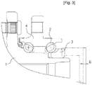
- Figs. 2 and 3 schematically show a prior art method of measuring a clearance of a hub bearing.
- a movement amount (A) of a flange of the outer ring 4 is first measured when the inner ring 3 is provisionally press-fitted to the hub 1. Thereafter, the inner ring 3 is completely press-fitted to the hub 1.
- a movement amount (B) of a tool is measured at the time of complete press-fitting.
- the amount of clearance of the hub bearing which is assembled in the above-described manner, can be represented as follows.
- the amount of clearance of the hub bearing A ⁇ B
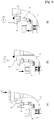
- Figs 4 and 5 show another prior art method of measuring a clearance of a hub bearing.
- the inner ring 3 is provisionally press-fitted to the hub 1 as shown in Fig. 4(a) . Also, a displacement (C) of the outer ring 4 relative to the hub 1 and a displacement (D) of the outer ring 4 relative to the inner ring 3 are measured respectively when a constant load is applied as shown in Fig. 4(b) and Fig. 4(c) .
- a displacement (C) of the outer ring 4 relative to the hub 1 and a displacement (D') of the outer ring 4 relative to the inner ring 3 are measured once again when a constant load is applied as shown in Fig. 5(b) and Fig. 5(c) .
- the method comprises fixing a hub to a frame when an inner ring is disposed on an outer periphery of the hub to be mounted to an axle and an outer ring is disposed to be opposed to an upper portion of the inner ring and a row of balls is disposed between the outer ring and the inner ring opposed thereto, contacting a press-fit jig to an outer surface of the inner ring and gradually press-fitting the inner ring to the hub, measuring a positional variation of the outer ring and a positional variation of the press-fit jig by an external measuring instrument, and measuring a displacement of the end surface of the inner ring after completely press-fitting the inner ring to the hub.
- an object of the present invention to provide a method of measuring a clearance of a hub bearing for vehicles when assembling the hub bearing. Specifically, an amount of clearance of a hub bearing can be measured simply in a single process to accomplish cost reduction. Further, the accumulated errors occurring due to many measurements are eliminated to enhance measurement reliability by measuring displacements of an outer ring and an end surface of an inner ring from a reference surface, while the inner ring is gradually press-fitted to a hub fixed to a lower jig- Technical Solution
- a method of measuring a clearance of a hub bearing for vehicles when assembling the hub bearing comprising the following: fixing a hub to a lower jig when a row of balls is disposed on an outer periphery of the hub to be mounted to an axle and an outer ring is disposed on an outer periphery of the row of balls; applying a load to an outer surface of the outer ring so as to prevent a vibration and a movement of the outer ring; contacting a press-fit jig to an end surface of the inner ring and gradually press-fitting the inner ring to an outer periphery of the hub; measuring a positional variation of the outer ring and a positional variation of the end surface of the inner ring by an external measuring instrument; measuring a displacement (G1) of an end surface of the inner ring when a movement (E) of the outer ring appears and the movement is detected at a gauge (A
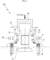
- Figs. 6 to 8 are schematic views showing a method of measuring a clearance of a hub bearing according to one embodiment of the present invention.
- Fig. 9 is a flow chart showing the method of measuring a clearance of a hub bearing according to the present invention
- a hub 10 is fixed to a lower jig 60 after a row of hub-side balls 41 is disposed on a periphery of the hub 10, through which an axle passes. Further, an outer ring 30 is disposed to be opposed to an outer periphery of the row of hub-side balls 41 and a row of inner ring-side balls 40 and an inner ring are disposed. (S100)
- a race of the outer ring, the row of balls and a race of the hub cannot be precisely contacted to each other due to an elastic force of a seal lip of an open seal.
- a load the extent of which is determined so that an elastic deformation does not occur in the hub-side ball (e.g., 5kgf)
- a gauge (Z) is installed to a portion of the outer ring.
- the inner ring 20 is gradually press fitted to the hub 10 after a cylindrical press-fit jig 50 is brought into contact with an end surface of the inner ring 20.
- a positional variation of the outer ring and a positional variation of the inner ring are measured by an external measuring instrument.
- the inner ring 20 is press-fitted until the end surface of the inner ring 20 is brought into complete contact with the end surface of the hub 10.
- the race of the hub, two rows of the balls, a race of the inner ring and two races of the outer ring are brought into contact with each other and the hub bearing 100 has a negative clearance.
- no movement (E) of the outer ring is shown in a gauge (A) for measuring the end surface of the outer ring even when the end surface of the inner ring and the end surface of the hub are fully contacted to each other, such a hub bearing is determined to have a positive clearance resulting from faulty assembly and is selected separately.
- a displacement (G2) of the end surface of the inner ring is measured when the end surface of the inner ring and the end surface of the hub are contacted to each other. (S150)
- a load of about 5 tons (various according to sizes of bearings) is applied as a final press-fit force during press-fitting the inner ring.
- a load means that a force, which can be applied to the hub bearing when orbital forming, fastening nuts or assembling a constant velocity joint of the following process is carried out, is realized during press-fitting the inner ring.
- the present process for measuring the amount of clearance is carried out before orbital forming, fastening nuts or assembling a constant velocity joint. If the press-fit jig is removed from the end surface of the inner ring when the load of 5 tons is applied to the end surface of the inner ring, the components constituting the hub bearing spring back. Therefore, the position of the end surface of the inner ring becomes higher when compared to a case, which is finally press-fitted by the press-fit jig.
- Measuring the displacement (G2) of the end surface of the inner ring is possible when applying the load of 5 tons or removing said load.
- the values of the measured amount of a clearance have different meanings. If the following process (e.g., orbital forming, fastening nuts, assembling a constant velocity joint) is completed, the amount of clearance is varied.
- the amount of clearance which is obtained by measuring the displacement (G2) of the end surface of the inner ring when the load of 5 tons is applied, reflects the above-mentioned variation of the amount of clearance.
- the amount of clearance which is obtained by measuring the displacement (G2) of the end surface of the inner ring when the load of 5 tons is removed, means the current assembly clearance of the hub bearing, which does not reflect the variation of the amount of clearance occurring in the following process.
- the amount of clearance of the hub bearing 100 which is measured and calculated during the above-described assembly of the hub bearing, can be represented as the following numerical formula.
- the amount of clearance ⁇ tht displacement G 1 of the end surface of the inner ring ⁇ the displacement G 2 of the end surface of the inner ring
- the amount of clearance can be measured simply and accurately during assembly process when compared to a prior art measuring method. Therefore, the process becomes very simple over a facility using the prior art measuring method and cost reduction is achieved with respect to manufacturing a facility. Further, the accumulated errors, which are generated due to many measurements in a prior art measuring method, are eliminated to thereby enhance measurement reliability.
Landscapes
- Physics & Mathematics (AREA)
- General Physics & Mathematics (AREA)
- Rolling Contact Bearings (AREA)
- A Measuring Device Byusing Mechanical Method (AREA)
Description
- The present invention relates to a method of measuring a clearance of a hub bearing for vehicles, and more particularly to a method of measuring a clearance of a hub bearing for vehicles, wherein an amount of a clearance known to have a great influence on a bearing life can be simply measured compared to a prior art measuring method. Specifically, this is performed by fixing a hub in the state where a row of hub-side balls is disposed and an outer ring is disposed on an outer periphery of the hub and press-fitting an inner ring by means of a press-fit jig and measuring an amount of press-fitting the inner ring from when a gauge installed to a portion of the outer ring begins to move when press-fitting the inner ring is completed.
- Generally, a hub bearing unit, which is mounted to an axle of the vehicle, supports a body of a vehicle. Since balls rotate in the hub bearing, the axle of the vehicle is allowed for smooth rotation. A clearance of the bearing has a great influence on the life of the bearing.
- The hub bearing unit, which is used for an axle of a vehicle, is consisted of a
hub 1,balls 2, aninner ring 3, anouter ring 4, a retainer, hub-bolts, etc., as shown inFig. 1 . A knuckle and theouter ring 4 are fastened to each other by bolts and the body of the vehicle is supported by the hub bearing. As shown inFig. 1 , a configuration of orbital forming an end portion of thehub 1 is generally used in the final assembly of the hub bearing unit so that an amount of a bearing pre-load is adjusted and a damage or disassembly of the hub bearing unit does not take place. - The amount of a clearance of the hub bearing, which is used for an axle of a vehicle, is intentionally adjusted by applying a pre-load when mounting the hub bearing to a drive axle, similar to conventional industrial bearings. As such, the bearing life is enhanced.
- In order to enhance the bearing life, the amount of clearance is adjusted to negative. The amount of a clearance, which is applied to the hub bearing, is about -40∼-50□, for example.
-
Figs. 2 and3 schematically show a prior art method of measuring a clearance of a hub bearing. Referring toFigs. 2 and3 , a movement amount (A) of a flange of theouter ring 4 is first measured when theinner ring 3 is provisionally press-fitted to thehub 1. Thereafter, theinner ring 3 is completely press-fitted to thehub 1. Also, a movement amount (B) of a tool is measured at the time of complete press-fitting. The amount of clearance of the hub bearing, which is assembled in the above-described manner, can be represented as follows.
-
Figs 4 and5 show another prior art method of measuring a clearance of a hub bearing. - Referring to
Figs. 4 and5 , theinner ring 3 is provisionally press-fitted to thehub 1 as shown inFig. 4(a) . Also, a displacement (C) of theouter ring 4 relative to thehub 1 and a displacement (D) of theouter ring 4 relative to theinner ring 3 are measured respectively when a constant load is applied as shown inFig. 4(b) and Fig. 4(c) . - Thereafter, the
inner ring 3 is completely press-fitted to thehub 1 by applying a load to theinner ring 3. After complete press-fitting ofFig. 5(a) , a displacement (C) of theouter ring 4 relative to thehub 1 and a displacement (D') of theouter ring 4 relative to theinner ring 3 are measured once again when a constant load is applied as shown inFig. 5(b) and Fig. 5(c) . - The amount of clearance of such assembled hub bearing is (C-C) + (D-D').
- Although the above-mentioned methods are different, their result values are the same.
- There are problems with the above-mentioned two methods in that a measuring method is complicated and a measurement must be made many times. Further, a facility with an inner ring press-fitting process is required. Additionally, there is inconvenience with the above-mentioned methods in that zero point setting and compensation of a measuring device must be consecutively carried out in order to solve accumulated errors that occur due to repeated measurements.
DocumentUS 5,620,263 discloses a method of measuring a clearance of a hub bearing for vehicles when assembling the hub bearing. The method comprises fixing a hub to a frame when an inner ring is disposed on an outer periphery of the hub to be mounted to an axle and an outer ring is disposed to be opposed to an upper portion of the inner ring and a row of balls is disposed between the outer ring and the inner ring opposed thereto, contacting a press-fit jig to an outer surface of the inner ring and gradually press-fitting the inner ring to the hub, measuring a positional variation of the outer ring and a positional variation of the press-fit jig by an external measuring instrument, and measuring a displacement of the end surface of the inner ring after completely press-fitting the inner ring to the hub. - Therefore, it is an object of the present invention to provide a method of measuring a clearance of a hub bearing for vehicles when assembling the hub bearing.
Specifically, an amount of clearance of a hub bearing can be measured simply in a single process to accomplish cost reduction. Further, the accumulated errors occurring due to many measurements are eliminated to enhance measurement reliability by measuring displacements of an outer ring and an end surface of an inner ring from a reference surface, while the inner ring is gradually press-fitted to a hub fixed to a lower jig-Technical Solution - Consistent with the foregoing object and in accordance with the invention as embodied broadly herein, there is provided a method of measuring a clearance of a hub bearing for vehicles when assembling the hub bearing, comprising the following: fixing a hub to a lower jig when a row of balls is disposed on an outer periphery of the hub to be mounted to an axle and an outer ring is disposed on an outer periphery of the row of balls; applying a load to an outer surface of the outer ring so as to prevent a vibration and a movement of the outer ring; contacting a press-fit jig to an end surface of the inner ring and gradually press-fitting the inner ring to an outer periphery of the hub; measuring a positional variation of the outer ring and a positional variation of the end surface of the inner ring by an external measuring instrument; measuring a displacement (G1) of an end surface of the inner ring when a movement (E) of the outer ring appears and the movement is detected at a gauge (A) after the inner ring is brought into contact with the balls; and measuring a displacement (G2) of the end surface of the inner ring after completely press-fitting the inner ring to the hub.
- The above object and features of the present invention will become more apparent from the following description of the preferred embodiments given in conjunction with the accompanying drawings.
-
Fig. 1 is a schematic view showing a configuration of a conventional hub bearing. -
Figs. 2 and3 are schematic views showing a prior art method of measuring a clearance of a hub bearing. -
Figs. 4 and5 are schematic views showing another prior art method of measuring a clearance of a hub bearing. -
Figs. 6 to 8 are schematic views showing a method of measuring a clearance of a hub bearing according to the present invention. -
Fig. 9 is a flow chart showing the method of measuring a clearance of a hub bearing according to the present invention. - A method of measuring a clearance of a hub bearing for vehicles according to the present invention will now be described in detail with reference to accompanying drawings.
-
Figs. 6 to 8 are schematic views showing a method of measuring a clearance of a hub bearing according to one embodiment of the present invention.Fig. 9 is a flow chart showing the method of measuring a clearance of a hub bearing according to the present invention - As shown in the figure, according to the method of measuring a clearance of a hub bearing 100 during assembly, a
hub 10 is fixed to alower jig 60 after a row of hub-side balls 41 is disposed on a periphery of thehub 10, through which an axle passes. Further, anouter ring 30 is disposed to be opposed to an outer periphery of the row of hub-side balls 41 and a row of inner ring-side balls 40 and an inner ring are disposed. (S100) - In the
outer ring 30, a race of the outer ring, the row of balls and a race of the hub cannot be precisely contacted to each other due to an elastic force of a seal lip of an open seal. To prevent movements caused by vibration that occur during press fitting of the inner ring, a load, the extent of which is determined so that an elastic deformation does not occur in the hub-side ball (e.g., 5kgf), is applied to an end surface of theouter ring 30. Then, a gauge (Z) is installed to a portion of the outer ring. - Next, the
inner ring 20 is gradually press fitted to thehub 10 after a cylindrical press-fit jig 50 is brought into contact with an end surface of theinner ring 20. (S120) Also, a positional variation of the outer ring and a positional variation of the inner ring (e.g., a positional variation of the press-fit jig 50) are measured by an external measuring instrument. (S130) - In the above-described state, a
contact surface 11 of the hub and acontact surface 21 of the inner ring are not brought into contact with each other. Further, aball contacting surface 22 of the inner ring and the row of inner ring-side balls 40 are not brought into contact with each other. - If press-fitting of the inner ring continues, then the
ball contacting surface 22 of the inner ring and the row of inner ring-side ball 40 are brought into contact with each other. Then, the press-fit force of the inner ring is transmitted to the outer ring via the balls, thereby causing the movement (E) of theouter ring 30. At this time, a displacement (G1) of the press-fit jig 50 (e.g., a displacement of the end surface of the inner ring) (G1) is measured. (S140) - Next, the
inner ring 20 is press-fitted until the end surface of theinner ring 20 is brought into complete contact with the end surface of thehub 10. When press-fitting is completed, the race of the hub, two rows of the balls, a race of the inner ring and two races of the outer ring are brought into contact with each other and the hub bearing 100 has a negative clearance. However, in case no movement (E) of the outer ring is shown in a gauge (A) for measuring the end surface of the outer ring even when the end surface of the inner ring and the end surface of the hub are fully contacted to each other, such a hub bearing is determined to have a positive clearance resulting from faulty assembly and is selected separately. - A displacement (G2) of the end surface of the inner ring is measured when the end surface of the inner ring and the end surface of the hub are contacted to each other. (S150)
- A load of about 5 tons (various according to sizes of bearings) is applied as a final press-fit force during press-fitting the inner ring. Such a load means that a force, which can be applied to the hub bearing when orbital forming, fastening nuts or assembling a constant velocity joint of the following process is carried out, is realized during press-fitting the inner ring. The present process for measuring the amount of clearance is carried out before orbital forming, fastening nuts or assembling a constant velocity joint. If the press-fit jig is removed from the end surface of the inner ring when the load of 5 tons is applied to the end surface of the inner ring, the components constituting the hub bearing spring back. Therefore, the position of the end surface of the inner ring becomes higher when compared to a case, which is finally press-fitted by the press-fit jig.
- Measuring the displacement (G2) of the end surface of the inner ring is possible when applying the load of 5 tons or removing said load. However, the values of the measured amount of a clearance have different meanings. If the following process (e.g., orbital forming, fastening nuts, assembling a constant velocity joint) is completed, the amount of clearance is varied. The amount of clearance, which is obtained by measuring the displacement (G2) of the end surface of the inner ring when the load of 5 tons is applied, reflects the above-mentioned variation of the amount of clearance. On the contrary, the amount of clearance, which is obtained by measuring the displacement (G2) of the end surface of the inner ring when the load of 5 tons is removed, means the current assembly clearance of the hub bearing, which does not reflect the variation of the amount of clearance occurring in the following process.
- The amount of clearance of the hub bearing 100, which is measured and calculated during the above-described assembly of the hub bearing, can be represented as the following numerical formula.

- According to the method of measuring a clearance of a hub bearing for vehicles of the present invention, the amount of clearance can be measured simply and accurately during assembly process when compared to a prior art measuring method. Therefore, the process becomes very simple over a facility using the prior art measuring method and cost reduction is achieved with respect to manufacturing a facility. Further, the accumulated errors, which are generated due to many measurements in a prior art measuring method, are eliminated to thereby enhance measurement reliability.
Claims (1)
- A method of measuring a clearance of a hub bearing for vehicles when assembling the hub bearing, comprising:fixing a hub (10) to a frame (60) when an inner ring (20) is disposed on an outer periphery of the hub (10) to be mounted to an axle and an outer ring (30) is disposed to be opposed to an upper portion of the inner ring (20) and a row of balls (40) is disposed between the outer ring (30) and the inner ring (20) opposed thereto (S100);applying a load to an outer surface of the outer ring (30) so as to prevent a movement of the outer ring (30) caused by a vibration that occurs during press-fitting of the inner ring (20) (S110);contacting a press-fit jig (50) to an outer surface of the inner ring (20) and gradually press-fitting the inner ring (20) to the hub (10) (S120);measuring a positional variation of the outer ring (30) and a positional variation of the press-fit jig (50) by an external measuring instrument (S130);measuring a displacement (G1) of an end surface (50) of the inner ring when a movement (E) of the outer ring (30) appears after the inner ring (20) is brought into contact with the row of balls (40) (S140);measuring a displacement (G2) of the end surface (50) of the inner ring after completely press-fitting the inner ring (20) to the hub (10) (S150); andmeasuring the amount of clearance of the hub bearing by subtracting G1 from G2.
Applications Claiming Priority (2)
| Application Number | Priority Date | Filing Date | Title |
|---|---|---|---|
| KR1020060048159A KR100797706B1 (en) | 2006-05-29 | 2006-05-29 | Measuring method of gap of hub bearing for automobile |
| PCT/KR2007/002605 WO2007139339A1 (en) | 2006-05-29 | 2007-05-29 | Method of measuring a clearance of a hub bearing for vehicles |
Publications (3)
| Publication Number | Publication Date |
|---|---|
| EP2008057A1 EP2008057A1 (en) | 2008-12-31 |
| EP2008057A4 EP2008057A4 (en) | 2014-06-25 |
| EP2008057B1 true EP2008057B1 (en) | 2018-11-28 |
Family
ID=38778812
Family Applications (1)
| Application Number | Title | Priority Date | Filing Date |
|---|---|---|---|
| EP07746752.0A Not-in-force EP2008057B1 (en) | 2006-05-29 | 2007-05-29 | Method of measuring a clearance of a hub bearing for vehicles |
Country Status (4)
| Country | Link |
|---|---|
| US (1) | US7617610B2 (en) |
| EP (1) | EP2008057B1 (en) |
| KR (1) | KR100797706B1 (en) |
| WO (1) | WO2007139339A1 (en) |
Families Citing this family (16)
| Publication number | Priority date | Publication date | Assignee | Title |
|---|---|---|---|---|
| KR101033024B1 (en) | 2009-02-23 | 2011-05-09 | 주식회사 일진글로벌 | How to measure the clearance of multi-row bearings |
| CN105057702A (en) * | 2012-03-26 | 2015-11-18 | 上海人本汽车轴承有限公司 | Wheel hub end face machining device and method |
| CN104122088A (en) * | 2014-07-31 | 2014-10-29 | 苏州施奇尔汽车技术有限公司 | Hub bearing negative play detection method and hub bearing negative play detection equipment |
| CN104613907B (en) * | 2014-12-16 | 2017-04-12 | 黑龙江大学 | Measurement component applied to inner ring measurement device of ball bearing automatic assembling machine |
| US9891136B2 (en) * | 2015-09-30 | 2018-02-13 | Deere & Company | Methods to determine a bearing setting |
| KR101819284B1 (en) * | 2015-10-27 | 2018-01-17 | 주식회사 포스코 | Clearance measuring apparatus for bearing and method of the same |
| CN105203064B (en) * | 2015-11-11 | 2017-10-10 | 济南易恒技术有限公司 | Hub bears clearance detection device |
| CN105783837B (en) * | 2016-04-13 | 2018-06-12 | 浙江省计量科学研究院 | A kind of third generation automobile hub bearing end-play automatic measurement mechanism |
| CN106524977A (en) * | 2016-09-28 | 2017-03-22 | 重庆长江轴承股份有限公司 | Three-point measurement method for negative clearance of third-generation hub bearing unit |
| CN106500643A (en) * | 2016-09-28 | 2017-03-15 | 重庆长江轴承股份有限公司 | The negative clearance wheel measuring method of third generation hub-bearing unit |
| CN108151691B (en) * | 2018-03-15 | 2019-08-13 | 大连理工大学 | A kind of measurement method and measuring device for four-row tapered roller bearing end-play |
| JP7559751B2 (en) | 2019-04-02 | 2024-10-02 | 株式会社ジェイテクト | Method for measuring axial clearance of double row rolling bearing and method for manufacturing double row rolling bearing |
| CN110296648B (en) * | 2019-06-12 | 2024-07-09 | 浙江万向精工有限公司 | Device and method for observing contact state of sealing ring of hub bearing unit |
| KR102630199B1 (en) | 2021-07-30 | 2024-01-29 | 한국과학기술연구원 | Anderon meter for cryogenic environment and Measuring method for bearing friction torque using the same |
| KR20240012234A (en) * | 2022-07-20 | 2024-01-29 | 주식회사 일진글로벌 | Wheel bearing for vehicle |
| CN121702330B (en) * | 2026-02-11 | 2026-04-17 | 浙江翰通汽车科技有限公司 | Automobile hub unit play detection machine and method |
Family Cites Families (12)
| Publication number | Priority date | Publication date | Assignee | Title |
|---|---|---|---|---|
| US4165636A (en) * | 1977-03-04 | 1979-08-28 | Odetics, Inc. | Method and means for measuring preloads in assembled mechanisms |
| JPS58121322A (en) * | 1982-01-14 | 1983-07-19 | Nippon Seiko Kk | Assembling method for race separation type double row angular ball bearing |
| US5224273A (en) * | 1991-05-28 | 1993-07-06 | United Technologies Corporation | Bearing clearance measurement |
| US5509198A (en) * | 1992-02-24 | 1996-04-23 | Nsk Ltd. | Preloading method for preload-adjustable rolling bearing and manufacture of the same |
| DE4498220C2 (en) * | 1993-10-28 | 2003-08-21 | Ntn Toyo Bearing Co Ltd | Method for measuring a bearing clearance and for mounting an axle bearing assembly |
| JPH07217648A (en) * | 1994-02-04 | 1995-08-15 | Nippon Seiko Kk | Method and apparatus for measuring preload clearance in double row rolling bearings |
| JPH07217649A (en) * | 1994-02-04 | 1995-08-15 | Nippon Seiko Kk | Method and apparatus for measuring preload clearance in double row rolling bearings |
| JP3216389B2 (en) * | 1994-02-04 | 2001-10-09 | 日本精工株式会社 | Method and apparatus for measuring the preload gap of double row rolling bearings |
| US6070325A (en) * | 1996-11-05 | 2000-06-06 | Koyo Seiko Co., Ltd. | Method for measuring a pre-load applied to a double-row rolling bearing |
| US6460423B1 (en) * | 2001-02-01 | 2002-10-08 | The Timken Company | Method of measuring preload in a multirow bearing assembly |
| KR20020074658A (en) * | 2001-03-21 | 2002-10-04 | 한국델파이주식회사 | Mounting structuer of hub bearing for vehicle |
| US7251892B2 (en) * | 2003-07-09 | 2007-08-07 | Temper Corporation | Bearing assembly spacer adjustable system and method for adjusting a spacer |
-
2006
- 2006-05-29 KR KR1020060048159A patent/KR100797706B1/en not_active Expired - Fee Related
-
2007
- 2007-05-29 EP EP07746752.0A patent/EP2008057B1/en not_active Not-in-force
- 2007-05-29 WO PCT/KR2007/002605 patent/WO2007139339A1/en not_active Ceased
- 2007-05-29 US US12/298,119 patent/US7617610B2/en active Active
Non-Patent Citations (1)
| Title |
|---|
| None * |
Also Published As
| Publication number | Publication date |
|---|---|
| US20090113735A1 (en) | 2009-05-07 |
| WO2007139339A1 (en) | 2007-12-06 |
| US7617610B2 (en) | 2009-11-17 |
| KR20070114499A (en) | 2007-12-04 |
| EP2008057A4 (en) | 2014-06-25 |
| KR100797706B1 (en) | 2008-01-23 |
| EP2008057A1 (en) | 2008-12-31 |
Similar Documents
| Publication | Publication Date | Title |
|---|---|---|
| US7617610B2 (en) | Method of measuring a clearance of a hub bearing for vehicles | |
| EP1962073B1 (en) | Sensor-equipped bearing for wheel | |
| US8578791B2 (en) | Sensor-equipped bearing for wheel | |
| US9512883B2 (en) | Method for manufacturing a wheel bearing apparatus | |
| JP2018021613A (en) | Hub unit bearing clearance measurement method | |
| JPH07217649A (en) | Method and apparatus for measuring preload clearance in double row rolling bearings | |
| EP1962074B1 (en) | Sensor-equipped bearing for wheel | |
| WO2020203982A1 (en) | Method of measuring double-row roller bearing axial clearance, and method of manufacturing double-row roller bearing | |
| US7628540B2 (en) | Bearing device for wheel | |
| US7874732B2 (en) | Bearing device for drive wheel | |
| JP2001225606A (en) | Wheel bearing device, and method of controlling bearing clearance gap | |
| JP2001004308A (en) | A method for measuring the internal clearance of a double row tapered roller bearing unit for wheel support | |
| JP5644679B2 (en) | Method for measuring preload of double row angular contact ball bearing, device for implementing the method, and double row angular contact ball bearing with guaranteed preload | |
| US8449194B2 (en) | Wheel bearing with sensor | |
| JP6880137B2 (en) | Axial clearance measurement method for wheel bearing devices | |
| JP2002081453A (en) | Caulking method of wheel bearing device | |
| JP4506028B2 (en) | Preload measuring method and preload measuring device for double row rolling bearing | |
| JP2003172371A (en) | Method for measuring the axial force of the inner ring of a rolling bearing unit for supporting wheels | |
| JP2007057259A (en) | Wheel bearing with sensor | |
| JP2007078615A (en) | Bearing with sensor for wheel | |
| CN101243310A (en) | Sensor-equipped wheel bearing | |
| JP2021177133A (en) | Preload measurement method of bearing device and manufacture method of bearing device | |
| JP7421451B2 (en) | Preload inspection method for wheel bearing devices | |
| CN116057288B (en) | Pre-pressing inspection method of bearing device for wheel | |
| JP4552951B2 (en) | Manufacturing method of bearing device |
Legal Events
| Date | Code | Title | Description |
|---|---|---|---|
| PUAI | Public reference made under article 153(3) epc to a published international application that has entered the european phase |
Free format text: ORIGINAL CODE: 0009012 |
|
| 17P | Request for examination filed |
Effective date: 20081022 |
|
| AK | Designated contracting states |
Kind code of ref document: A1 Designated state(s): AT BE BG CH CY CZ DE DK EE ES FI FR GB GR HU IE IS IT LI LT LU LV MC MT NL PL PT RO SE SI SK TR |
|
| AX | Request for extension of the european patent |
Extension state: AL BA HR MK RS |
|
| DAX | Request for extension of the european patent (deleted) | ||
| A4 | Supplementary search report drawn up and despatched |
Effective date: 20140522 |
|
| RIC1 | Information provided on ipc code assigned before grant |
Ipc: G01B 21/16 20060101AFI20140516BHEP Ipc: G01B 5/14 20060101ALI20140516BHEP |
|
| GRAP | Despatch of communication of intention to grant a patent |
Free format text: ORIGINAL CODE: EPIDOSNIGR1 |
|
| STAA | Information on the status of an ep patent application or granted ep patent |
Free format text: STATUS: GRANT OF PATENT IS INTENDED |
|
| INTG | Intention to grant announced |
Effective date: 20180628 |
|
| GRAS | Grant fee paid |
Free format text: ORIGINAL CODE: EPIDOSNIGR3 |
|
| GRAA | (expected) grant |
Free format text: ORIGINAL CODE: 0009210 |
|
| STAA | Information on the status of an ep patent application or granted ep patent |
Free format text: STATUS: THE PATENT HAS BEEN GRANTED |
|
| AK | Designated contracting states |
Kind code of ref document: B1 Designated state(s): AT BE BG CH CY CZ DE DK EE ES FI FR GB GR HU IE IS IT LI LT LU LV MC MT NL PL PT RO SE SI SK TR |
|
| REG | Reference to a national code |
Ref country code: GB Ref legal event code: FG4D |
|
| REG | Reference to a national code |
Ref country code: CH Ref legal event code: EP |
|
| REG | Reference to a national code |
Ref country code: AT Ref legal event code: REF Ref document number: 1070740 Country of ref document: AT Kind code of ref document: T Effective date: 20181215 |
|
| REG | Reference to a national code |
Ref country code: DE Ref legal event code: R096 Ref document number: 602007056973 Country of ref document: DE |
|
| REG | Reference to a national code |
Ref country code: IE Ref legal event code: FG4D |
|
| REG | Reference to a national code |
Ref country code: NL Ref legal event code: MP Effective date: 20181128 |
|
| REG | Reference to a national code |
Ref country code: LT Ref legal event code: MG4D |
|
| REG | Reference to a national code |
Ref country code: AT Ref legal event code: MK05 Ref document number: 1070740 Country of ref document: AT Kind code of ref document: T Effective date: 20181128 |
|
| PG25 | Lapsed in a contracting state [announced via postgrant information from national office to epo] |
Ref country code: LV Free format text: LAPSE BECAUSE OF FAILURE TO SUBMIT A TRANSLATION OF THE DESCRIPTION OR TO PAY THE FEE WITHIN THE PRESCRIBED TIME-LIMIT Effective date: 20181128 Ref country code: ES Free format text: LAPSE BECAUSE OF FAILURE TO SUBMIT A TRANSLATION OF THE DESCRIPTION OR TO PAY THE FEE WITHIN THE PRESCRIBED TIME-LIMIT Effective date: 20181128 Ref country code: LT Free format text: LAPSE BECAUSE OF FAILURE TO SUBMIT A TRANSLATION OF THE DESCRIPTION OR TO PAY THE FEE WITHIN THE PRESCRIBED TIME-LIMIT Effective date: 20181128 Ref country code: AT Free format text: LAPSE BECAUSE OF FAILURE TO SUBMIT A TRANSLATION OF THE DESCRIPTION OR TO PAY THE FEE WITHIN THE PRESCRIBED TIME-LIMIT Effective date: 20181128 Ref country code: IS Free format text: LAPSE BECAUSE OF FAILURE TO SUBMIT A TRANSLATION OF THE DESCRIPTION OR TO PAY THE FEE WITHIN THE PRESCRIBED TIME-LIMIT Effective date: 20190328 Ref country code: FI Free format text: LAPSE BECAUSE OF FAILURE TO SUBMIT A TRANSLATION OF THE DESCRIPTION OR TO PAY THE FEE WITHIN THE PRESCRIBED TIME-LIMIT Effective date: 20181128 Ref country code: BG Free format text: LAPSE BECAUSE OF FAILURE TO SUBMIT A TRANSLATION OF THE DESCRIPTION OR TO PAY THE FEE WITHIN THE PRESCRIBED TIME-LIMIT Effective date: 20190228 |
|
| PG25 | Lapsed in a contracting state [announced via postgrant information from national office to epo] |
Ref country code: SE Free format text: LAPSE BECAUSE OF FAILURE TO SUBMIT A TRANSLATION OF THE DESCRIPTION OR TO PAY THE FEE WITHIN THE PRESCRIBED TIME-LIMIT Effective date: 20181128 Ref country code: PT Free format text: LAPSE BECAUSE OF FAILURE TO SUBMIT A TRANSLATION OF THE DESCRIPTION OR TO PAY THE FEE WITHIN THE PRESCRIBED TIME-LIMIT Effective date: 20190328 Ref country code: GR Free format text: LAPSE BECAUSE OF FAILURE TO SUBMIT A TRANSLATION OF THE DESCRIPTION OR TO PAY THE FEE WITHIN THE PRESCRIBED TIME-LIMIT Effective date: 20190301 |
|
| PG25 | Lapsed in a contracting state [announced via postgrant information from national office to epo] |
Ref country code: NL Free format text: LAPSE BECAUSE OF FAILURE TO SUBMIT A TRANSLATION OF THE DESCRIPTION OR TO PAY THE FEE WITHIN THE PRESCRIBED TIME-LIMIT Effective date: 20181128 |
|
| PG25 | Lapsed in a contracting state [announced via postgrant information from national office to epo] |
Ref country code: DK Free format text: LAPSE BECAUSE OF FAILURE TO SUBMIT A TRANSLATION OF THE DESCRIPTION OR TO PAY THE FEE WITHIN THE PRESCRIBED TIME-LIMIT Effective date: 20181128 Ref country code: PL Free format text: LAPSE BECAUSE OF FAILURE TO SUBMIT A TRANSLATION OF THE DESCRIPTION OR TO PAY THE FEE WITHIN THE PRESCRIBED TIME-LIMIT Effective date: 20181128 Ref country code: IT Free format text: LAPSE BECAUSE OF FAILURE TO SUBMIT A TRANSLATION OF THE DESCRIPTION OR TO PAY THE FEE WITHIN THE PRESCRIBED TIME-LIMIT Effective date: 20181128 Ref country code: CZ Free format text: LAPSE BECAUSE OF FAILURE TO SUBMIT A TRANSLATION OF THE DESCRIPTION OR TO PAY THE FEE WITHIN THE PRESCRIBED TIME-LIMIT Effective date: 20181128 |
|
| REG | Reference to a national code |
Ref country code: DE Ref legal event code: R097 Ref document number: 602007056973 Country of ref document: DE |
|
| PG25 | Lapsed in a contracting state [announced via postgrant information from national office to epo] |
Ref country code: RO Free format text: LAPSE BECAUSE OF FAILURE TO SUBMIT A TRANSLATION OF THE DESCRIPTION OR TO PAY THE FEE WITHIN THE PRESCRIBED TIME-LIMIT Effective date: 20181128 Ref country code: EE Free format text: LAPSE BECAUSE OF FAILURE TO SUBMIT A TRANSLATION OF THE DESCRIPTION OR TO PAY THE FEE WITHIN THE PRESCRIBED TIME-LIMIT Effective date: 20181128 Ref country code: SK Free format text: LAPSE BECAUSE OF FAILURE TO SUBMIT A TRANSLATION OF THE DESCRIPTION OR TO PAY THE FEE WITHIN THE PRESCRIBED TIME-LIMIT Effective date: 20181128 |
|
| PLBE | No opposition filed within time limit |
Free format text: ORIGINAL CODE: 0009261 |
|
| STAA | Information on the status of an ep patent application or granted ep patent |
Free format text: STATUS: NO OPPOSITION FILED WITHIN TIME LIMIT |
|
| PG25 | Lapsed in a contracting state [announced via postgrant information from national office to epo] |
Ref country code: SI Free format text: LAPSE BECAUSE OF FAILURE TO SUBMIT A TRANSLATION OF THE DESCRIPTION OR TO PAY THE FEE WITHIN THE PRESCRIBED TIME-LIMIT Effective date: 20181128 |
|
| 26N | No opposition filed |
Effective date: 20190829 |
|
| REG | Reference to a national code |
Ref country code: CH Ref legal event code: PL |
|
| REG | Reference to a national code |
Ref country code: DE Ref legal event code: R082 Ref document number: 602007056973 Country of ref document: DE Representative=s name: MANITZ FINSTERWALD PATENT- UND RECHTSANWALTSPA, DE Ref country code: DE Ref legal event code: R081 Ref document number: 602007056973 Country of ref document: DE Owner name: ILJIN GLOBAL CO., LTD., KR Free format text: FORMER OWNER: IL JIN GLOBAL CO., LTD., SEOUL, KR Ref country code: DE Ref legal event code: R081 Ref document number: 602007056973 Country of ref document: DE Owner name: ILJIN GLOBAL CO., LTD., KR Free format text: FORMER OWNER: ILJIN ENTERPRISE CO., LTD., SEOUL, KR |
|
| GBPC | Gb: european patent ceased through non-payment of renewal fee |
Effective date: 20190529 |
|
| PG25 | Lapsed in a contracting state [announced via postgrant information from national office to epo] |
Ref country code: MC Free format text: LAPSE BECAUSE OF FAILURE TO SUBMIT A TRANSLATION OF THE DESCRIPTION OR TO PAY THE FEE WITHIN THE PRESCRIBED TIME-LIMIT Effective date: 20181128 Ref country code: CH Free format text: LAPSE BECAUSE OF NON-PAYMENT OF DUE FEES Effective date: 20190531 Ref country code: LI Free format text: LAPSE BECAUSE OF NON-PAYMENT OF DUE FEES Effective date: 20190531 |
|
| REG | Reference to a national code |
Ref country code: BE Ref legal event code: MM Effective date: 20190531 |
|
| PG25 | Lapsed in a contracting state [announced via postgrant information from national office to epo] |
Ref country code: LU Free format text: LAPSE BECAUSE OF NON-PAYMENT OF DUE FEES Effective date: 20190529 |
|
| PG25 | Lapsed in a contracting state [announced via postgrant information from national office to epo] |
Ref country code: TR Free format text: LAPSE BECAUSE OF FAILURE TO SUBMIT A TRANSLATION OF THE DESCRIPTION OR TO PAY THE FEE WITHIN THE PRESCRIBED TIME-LIMIT Effective date: 20181128 |
|
| PG25 | Lapsed in a contracting state [announced via postgrant information from national office to epo] |
Ref country code: IE Free format text: LAPSE BECAUSE OF NON-PAYMENT OF DUE FEES Effective date: 20190529 Ref country code: GB Free format text: LAPSE BECAUSE OF NON-PAYMENT OF DUE FEES Effective date: 20190529 |
|
| PG25 | Lapsed in a contracting state [announced via postgrant information from national office to epo] |
Ref country code: BE Free format text: LAPSE BECAUSE OF NON-PAYMENT OF DUE FEES Effective date: 20190531 |
|
| PG25 | Lapsed in a contracting state [announced via postgrant information from national office to epo] |
Ref country code: FR Free format text: LAPSE BECAUSE OF NON-PAYMENT OF DUE FEES Effective date: 20190531 |
|
| PG25 | Lapsed in a contracting state [announced via postgrant information from national office to epo] |
Ref country code: CY Free format text: LAPSE BECAUSE OF FAILURE TO SUBMIT A TRANSLATION OF THE DESCRIPTION OR TO PAY THE FEE WITHIN THE PRESCRIBED TIME-LIMIT Effective date: 20181128 |
|
| PG25 | Lapsed in a contracting state [announced via postgrant information from national office to epo] |
Ref country code: MT Free format text: LAPSE BECAUSE OF FAILURE TO SUBMIT A TRANSLATION OF THE DESCRIPTION OR TO PAY THE FEE WITHIN THE PRESCRIBED TIME-LIMIT Effective date: 20181128 Ref country code: HU Free format text: LAPSE BECAUSE OF FAILURE TO SUBMIT A TRANSLATION OF THE DESCRIPTION OR TO PAY THE FEE WITHIN THE PRESCRIBED TIME-LIMIT; INVALID AB INITIO Effective date: 20070529 |
|
| PGFP | Annual fee paid to national office [announced via postgrant information from national office to epo] |
Ref country code: DE Payment date: 20230727 Year of fee payment: 17 |
|
| REG | Reference to a national code |
Ref country code: DE Ref legal event code: R119 Ref document number: 602007056973 Country of ref document: DE |
|
| PG25 | Lapsed in a contracting state [announced via postgrant information from national office to epo] |
Ref country code: DE Free format text: LAPSE BECAUSE OF NON-PAYMENT OF DUE FEES Effective date: 20241203 |