EP2007463B1 - Flexible device shaft with angled spiral wrap - Google Patents
Flexible device shaft with angled spiral wrap Download PDFInfo
- Publication number
- EP2007463B1 EP2007463B1 EP06840235.3A EP06840235A EP2007463B1 EP 2007463 B1 EP2007463 B1 EP 2007463B1 EP 06840235 A EP06840235 A EP 06840235A EP 2007463 B1 EP2007463 B1 EP 2007463B1
- Authority
- EP
- European Patent Office
- Prior art keywords
- shaft
- surface edge
- wrap
- edge
- trailing
- Prior art date
- Legal status (The legal status is an assumption and is not a legal conclusion. Google has not performed a legal analysis and makes no representation as to the accuracy of the status listed.)
- Active
Links
- 239000002184 metal Substances 0.000 claims description 14
- 229910052751 metal Inorganic materials 0.000 claims description 14
- 239000004033 plastic Substances 0.000 claims description 13
- 229920003023 plastic Polymers 0.000 claims description 13
- 238000003384 imaging method Methods 0.000 claims description 4
- 229910010293 ceramic material Inorganic materials 0.000 claims 1
- 238000005452 bending Methods 0.000 description 14
- 238000005520 cutting process Methods 0.000 description 12
- 238000000034 method Methods 0.000 description 11
- 239000000463 material Substances 0.000 description 8
- 230000008901 benefit Effects 0.000 description 5
- 230000000295 complement effect Effects 0.000 description 4
- 210000003484 anatomy Anatomy 0.000 description 3
- 238000001125 extrusion Methods 0.000 description 3
- 238000005286 illumination Methods 0.000 description 3
- 230000007423 decrease Effects 0.000 description 2
- 150000002739 metals Chemical class 0.000 description 2
- 210000001113 umbilicus Anatomy 0.000 description 2
- 239000004677 Nylon Substances 0.000 description 1
- 239000004698 Polyethylene Substances 0.000 description 1
- 230000008572 axis elongation Effects 0.000 description 1
- 238000001574 biopsy Methods 0.000 description 1
- 239000004568 cement Substances 0.000 description 1
- 239000000919 ceramic Substances 0.000 description 1
- 150000001875 compounds Chemical class 0.000 description 1
- 238000010276 construction Methods 0.000 description 1
- 230000003247 decreasing effect Effects 0.000 description 1
- 239000012530 fluid Substances 0.000 description 1
- 239000000446 fuel Substances 0.000 description 1
- 239000007789 gas Substances 0.000 description 1
- 229920001903 high density polyethylene Polymers 0.000 description 1
- 239000004700 high-density polyethylene Substances 0.000 description 1
- 238000003780 insertion Methods 0.000 description 1
- 230000037431 insertion Effects 0.000 description 1
- 230000001788 irregular Effects 0.000 description 1
- 239000007788 liquid Substances 0.000 description 1
- 238000005007 materials handling Methods 0.000 description 1
- 238000012986 modification Methods 0.000 description 1
- 230000004048 modification Effects 0.000 description 1
- 230000007935 neutral effect Effects 0.000 description 1
- 229920001778 nylon Polymers 0.000 description 1
- -1 polyethylene Polymers 0.000 description 1
- 229920000573 polyethylene Polymers 0.000 description 1
- 229920000642 polymer Polymers 0.000 description 1
- 230000003014 reinforcing effect Effects 0.000 description 1
- 239000012779 reinforcing material Substances 0.000 description 1
- 239000004576 sand Substances 0.000 description 1
- 239000000758 substrate Substances 0.000 description 1
- 238000002560 therapeutic procedure Methods 0.000 description 1
Images


Classifications
-
- A—HUMAN NECESSITIES
- A61—MEDICAL OR VETERINARY SCIENCE; HYGIENE
- A61M—DEVICES FOR INTRODUCING MEDIA INTO, OR ONTO, THE BODY; DEVICES FOR TRANSDUCING BODY MEDIA OR FOR TAKING MEDIA FROM THE BODY; DEVICES FOR PRODUCING OR ENDING SLEEP OR STUPOR
- A61M25/00—Catheters; Hollow probes
- A61M25/0043—Catheters; Hollow probes characterised by structural features
-
- A—HUMAN NECESSITIES
- A61—MEDICAL OR VETERINARY SCIENCE; HYGIENE
- A61B—DIAGNOSIS; SURGERY; IDENTIFICATION
- A61B1/00—Instruments for performing medical examinations of the interior of cavities or tubes of the body by visual or photographical inspection, e.g. endoscopes; Illuminating arrangements therefor
- A61B1/00064—Constructional details of the endoscope body
- A61B1/00071—Insertion part of the endoscope body
-
- A—HUMAN NECESSITIES
- A61—MEDICAL OR VETERINARY SCIENCE; HYGIENE
- A61B—DIAGNOSIS; SURGERY; IDENTIFICATION
- A61B1/00—Instruments for performing medical examinations of the interior of cavities or tubes of the body by visual or photographical inspection, e.g. endoscopes; Illuminating arrangements therefor
- A61B1/005—Flexible endoscopes
- A61B1/0051—Flexible endoscopes with controlled bending of insertion part
- A61B1/0055—Constructional details of insertion parts, e.g. vertebral elements
-
- A—HUMAN NECESSITIES
- A61—MEDICAL OR VETERINARY SCIENCE; HYGIENE
- A61M—DEVICES FOR INTRODUCING MEDIA INTO, OR ONTO, THE BODY; DEVICES FOR TRANSDUCING BODY MEDIA OR FOR TAKING MEDIA FROM THE BODY; DEVICES FOR PRODUCING OR ENDING SLEEP OR STUPOR
- A61M25/00—Catheters; Hollow probes
- A61M25/0009—Making of catheters or other medical or surgical tubes
- A61M25/0013—Weakening parts of a catheter tubing, e.g. by making cuts in the tube or reducing thickness of a layer at one point to adjust the flexibility
-
- Y—GENERAL TAGGING OF NEW TECHNOLOGICAL DEVELOPMENTS; GENERAL TAGGING OF CROSS-SECTIONAL TECHNOLOGIES SPANNING OVER SEVERAL SECTIONS OF THE IPC; TECHNICAL SUBJECTS COVERED BY FORMER USPC CROSS-REFERENCE ART COLLECTIONS [XRACs] AND DIGESTS
- Y10—TECHNICAL SUBJECTS COVERED BY FORMER USPC
- Y10T—TECHNICAL SUBJECTS COVERED BY FORMER US CLASSIFICATION
- Y10T29/00—Metal working
- Y10T29/49—Method of mechanical manufacture
- Y10T29/49995—Shaping one-piece blank by removing material
Definitions
- the present invention relates to medical devices in general and, in particular, to minimally invasive medical instruments such as catheters and endoscopes.
- Such devices generally comprise an elongated shaft that is directed to a point of interest.
- the devices allow a physician to perform a desired task such as taking biopsy samples, performing a therapeutic procedure, or viewing the point of interest from a position outside the body of the patient.
- the shaft often includes an outer sheath, a reinforcing braid, and a spiral wrap.
- the spiral wrap increases the column strength of the shaft as well as the crush and kink resistance of the shaft without adding substantially to the stiffness of the shaft.
- a spiral wrap can be viewed as a helical strip of material separated by gaps.
- An individual wrap is the portion of the helix making one complete revolution of 360° around the longitudinal axis of the helix. Each wrap has a leading surface edge and a trailing surface edge.
- the conventional material used for a spiral wrap is metal.
- metal spiral wraps are expensive to produce because flat metal strips cannot easily be processed into a helix.
- the thin wall and wide gaps of the metal spiral make it a poor substrate for further processing.
- Plastics can be used for a spiral wrap, but plastics are more flexible than metals. Therefore, if a plastic is used, the plastic spiral wrap will require a greater wall thickness and more tightly spaced wraps as compared to metal to provide comparable crush and kink resistance.
- a disadvantage with plastic spiral wraps is the larger spiral wall thickness combined with the more tightly spaced wraps which causes the surface edges of adjacent wraps to touch as the spiral wrap is bent. As a result of touching, individual wraps push away from each other. This shifts the neutral axis of the shaft when under bending loads and results in axis elongation of the shaft, which, in turn, causes reduced flexibility of the shaft. This reduced flexibility may interfere with accurately tracking a patient's anatomy with the shaft.
- embodiments of the present invention are related to a medical device including a shaft having a spiral wrap that reduces inadvertent axial elongation of the shaft during bending, which permits greater flexibility of the shaft.
- the spiral wrap has beveled edges so that the edges may nest within one another. Nesting of adjacent wraps provides the shaft with increased flexibility by reducing elongation of the shaft and greater shaft column strength since wraps are less prone to sliding past one another.
- FIGURE 1 illustrates a conventional spiral wrap 100 being cut from a plastic tube 110.
- the spiral wrap 100 is used as a reinforcing material in a shaft of a medical device, such as an endoscope or catheter.
- the spiral wrap 100 can be formed via a continuous extrusion process that first forms the cylindrical plastic tube 110. Such extrusion process pushes the tube forward, and a cutting instrument 108 is rotated around the tube 110 to cut a continuous slot in the wall of the tube 110. Because the tube 110 is moving forward, the cutting process creates a helical pattern in the tube to produce the spiral 100.
- the spiral wrap may be created by holding the tube 110 stationary and moving the cutting instrument 108 in a helical pattern while cutting the tube's 110 wall.
- the spiral wrap 100 can be viewed as a series of connected individual wraps, such as wraps 102.
- a rectangular coordinate system can be drawn where the X-axis is parallel to the central, longitudinal axis of the spiral wrap 100.
- the Y-and Z-axes are both perpendicular to the X-axis and to each other.
- the plane of the cutting instrument 108 that cuts the spiral wrap 100 from the extruded tube 110 is rotated along only one axis from a plane perpendicular to the X-axis about the Z-axis.
- the angle that the cutting instrument 108 makes with such a plane perpendicular to the X-axis corresponds to the angle the slot makes with the longitudinal axis of tube 110.
- spiral wrap 102 has a leading surface edge 104 and a trailing surface edge 106 that are composed of an infinite number of radial lines that are perpendicular to the X-axis and to the longitudinal axis of the spiral 100.
- the cross section along any point of the single spiral wrap 102 shows the leading surface edge 104 and the trailing surface edge 106 are perpendicular to the top surface 112 of the wrap 102, which is also perpendicular to the longitudinal axis of the spiral wrap 100 of FIGURE 1 .
- the top surface 112 also defines the outer diameter surface of the spiral, as a whole.
- the angle ⁇ is defined as the angle measured from the X-axis to the radial line defined by the leading surface edge 104 or the trailing surface edge 106.
- ⁇ is equal to 90°.
- a spiral wrap 102 will have a limited ability to bend due to the leading surface edge 104 of one wrap coming into contact with the trailing surface edge 106 of an adjacent wrap when the edges 104 and 106 are straight.
- a spiral wrap has a leading surface edge, and a trailing surface edge, that are not perpendicular to the top surface 112 or to the longitudinal axis.
- the angle ⁇ of these edges can, in theory, range from an angle that is greater than 0° to less than 90°, and greater than 90° to less than 180°.
- the angle ⁇ is 30° to 60° or 120° to 150°. More preferably, the angle ⁇ is 40° to 50° or 130° to 140°. In one configuration, the angle ⁇ is 50° to 60°, and in one particular configuration, the angle ⁇ is about 55°.
- a spiral wrap with leading and trailing edges that have an angle ⁇ being something other than 90° are said to be beveled.
- other examples of wraps that can nest with, cooperate with, or complement one another may not have completely planar trailing and leading edges, but can include arcuate surfaces and multi-planer surfaces.
- An embodiment in accordance with the present invention is a method for forming a spiral with wraps wherein the leading surface edge and the trailing surface edge are beveled. Beveling the edges will result in adjacent wraps capable of nesting within one another when the shaft is bent to a certain degree and the edges are in close enough proximity. Furthermore, beveling the surface edges will result in a spiral capable of a smaller bending radius as compared to a spiral having non-beveled surface edges. To bevel the edges, the cutting instrument 108 can be rotated in two planes so that the plane of the cutting instrument 108 no longer cuts a slot that is composed of lines perpendicular to the X-axis, or to the top surface 112 of the wrap 102.
- any leading surface edge 104 of any wrap such as wrap 102
- any trailing surface edge 106 of any wrap such as wrap 102
- FIGURE 3 an illustration of a spiral wrap 200 having an overcut leading edge is provided.
- Arrow 240 indicates the "leading" direction
- arrow 242 indicates the trailing direction in FIGURES 3-6 .
- the spiral wrap 200 includes adjacent wraps 202 and 208 that are separated by a gap.
- the gap can be substantially zero or the gap can vary from zero to a predetermined amount.
- the overcut leading edge 204 of wrap 202 may nest within the undercut trailing edge 216 of the adjacent wrap 208.
- “nest” or “nesting” refers to the situation where a portion of the leading surface edge of one wrap fits within a portion of the trailing surface edge of an adjacent wrap, such as by overlapping, etc.
- embodiments of the present invention include wraps that have complementary and/or cooperating edges, such that a portion of one edge may complement and/or cooperate with an adjacent edge to either decrease the bending radius of a spiral, or to increase the lateral strength, i.e., the resistance of the spiral to kink. Furthermore, unlike the adjacent square edges of the prior art, complementary and/or cooperating edges may also prevent the wraps from slipping past one another in the radial direction.
- the capability of wraps to nest while bending the spiral wrap 200 decreases the bending radius of a spiral, i.e., increases the flexibility, and results in tighter bending capability.
- the leading edge 204 may be undercut and the trailing edge 216 may be overcut. In the latter situation, the trailing edge of a forward wrap will nest within the undercut leading edge of an adjacent and rear wrap.
- the degree of flexibility of the spiral wrap 200 that is capable of nesting within one another is increased in comparison to the spiral wrap 100 ( FIGURE 1 ), because adjacent wraps will nest within one another instead of abutting against one another.
- the angle ⁇ is defined by the X-axis and the radial lines on which the leading surface edge 204 and the trailing surface edge 206 lie.
- the angle ⁇ can be any angle from greater than 0° to less than 90° or greater than 90° to less than 180°.
- the angle ⁇ is greater than 0°, but less than 90°, the leading surface edge 204 is undercut, and the trailing surface edge 206 is overcut.
- the angle ⁇ is greater than 90°, but less than 180°, the leading surface edge 204 is overcut, and the trailing surface edge 206 is undercut.
- the depth of the cut can be any thickness ranging from the full thickness of the wall measured from the outer diameter to the inner diameter, or from the inner diameter to the outer diameter. Alternatively, the depth of the cut can be less than the full thickness.
- any one, some, or all of the individual wraps in the spiral wrap 202 can be beveled.
- only a section of the spiral wrap 200 can have wraps with overcut or undercut leading surface edges and trailing surface edges. For example, sometimes it may be desired to provide the distal section of a shaft with greater flexibility (greater bending capability) as compared to the proximal section. In this situation, only wraps in the distal section can be modified to have beveled edges.
- the wraps of the proximal section and center section, which is between the distal section and the proximal section are left unmodified, providing increased column strength in the proximal region (with angles closer to 90°).
- FIGURE 5 is an illustration of a cross section of the spiral wrap 200 of FIGURE 3 .
- the spiral wrap 200 includes a series of adjacent wraps, two of which are numbered 202 and 208.
- Wrap 202 has a leading surface edge 204.
- the adjacent and forward wrap 208 has a trailing surface edge 216.
- FIGURE 5 is an illustration of the spiral 200 in the unflexed or unbent configuration. In this configuration, the leading surface edge 204 of wrap 202 is separated by a gap from the trailing surface edge 216 of wrap 208. Alternatively, the gap between wraps 202 and 208 can be substantially zero.
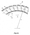
- FIGURE 6A is a cross-sectional illustration of the spiral wrap 200 of FIGURE 5 in the flexed or bent configuration that has reached the limit of bending without distorting the spiral material. This is an advantage when the gap between wraps is zero or close to it with a larger gap, nesting may be unnecessary, but kinking is more likely.
- the leading surface edge 204 of wrap 202 is nested within the trailing surface edge 216 of the forward and adjacent wrap 208. Having wraps in the spiral 200, wherein the wraps contain beveled surface edges allow the individual wraps to nest within each other when the spiral is bent or flexed.
- Beveling the surface edges 204 and 216 of wraps 202, 208 in the spiral 200 provides the spiral 200 with a smaller bending radius (r b ) compared to a spiral that does not have beveled surface edges. This is because the wraps with beveled surface edges may nest within one another, increasing the ability of the shaft to bend and reducing the bending radius (r b ). Wraps with unbeveled or perpendicular surface edges cannot nest within one another and push away from each other when under a bending load, therefore decreasing flexibility.
- a spiral wrap 200b has adjacent wraps 208b and 202b.
- the wrap 208b has a trailing surface edge 216b.
- the wrap 202b has the leading surface edge 204b.
- the trailing surface edge 216b and the leading surface edge 204b are cut at a 90° angle with respect to the central axis of the spiral wrap 200b. Therefore, due to the straight cut of edges 216b and 204b, the bending radius (r b ) is greater than the bending radius (r b ) of the spiral wrap 200 of FIGURE 6A , all other things being equal.
- a medical device such as an endoscope 320
- a spiral wrap 300 formed in accordance with one embodiment of the present invention, wherein the spiral wrap 300 is surrounded with a cover sheath.
- the endoscope 320 includes a distal shaft 334 (insertion tube) having a spiral wrap 300.
- the distal shaft 334 is connected to a control handle 324, through which the endoscope 320 is controlled.
- the control handle 324 is connected via an umbilicus 380 to a control cabinet (not shown).
- the umbilicus 380 provides passageways and cables for the passing of electrical signals, current, fluids, and gasses to and from the control cabinet (not shown) to the control handle 324 and ultimately to the distal shaft 334 to be delivered to a target area in a patient.
- the spiral wrap 300 is a spiral made in accordance with an embodiment of the present invention.
- the shaft 324 includes the spiral wrap 300 and may also include a cover sheath, a metal braid, and tape, or other materials, within the shaft 334.
- the distal shaft 334 of the endoscope 320 will typically have devices at the distal end that provide illumination, imaging, and steering capability, such as illumination/imaging device 382 steering cables 384, to assist with tracking the shaft 334 though the patient's anatomy.
- One or more electrical cables are included within the distal shaft 334 to power the illumination and imaging devices, and to carry signals to a processor to convert the signals into images that can be viewed at the control cabinet, for example.
- the distal shaft 334 of the endoscope 320 can have one or more lumens to carry liquids, gases, and devices to a target area. The additional components of shaft 334 described above are not discussed at length in this application for brevity.
- FIGURES 8A and 8B illustrate an alternate embodiment of the present invention, wherein a spiral wrap initially has individual wraps whose leading surface edge 104 and trailing surface edge 106 are generally perpendicular to the X-axis and to the longitudinal axis of the spiral.
- An embodiment of the present invention is a method for beveling the leading surface edge 104 and the trailing surface edge 106.
- FIGURE 8A is a cross-sectional illustration of a wrap 102 wherein the leading surface edge 104 and the trailing surface edge 106 have been cut perpendicular to the top surface 112 of the wrap 102, and perpendicular to the X-axis. This is the result of a first cut being made perpendicular to the top surface 112 and perpendicular to a plane that is rotated along a single axis from the X-axis, as illustrated in FIGURE 1 .
- a second and third cut may be performed on the leading surface edge 104 and the trailing surface edge 106 at the cut lines 120 and 122, respectively. Cut line 120 bevels the leading surface edge 104 into an overcut. Cut line 122 bevels the trailing surface edge 106 into an undercut
- FIGURE 8B a cross-sectional illustration of the wrap 102 after performing two additional cuts is illustrated.
- a second cut at the leading surface edge 104 along cut line 120 has resulted in a new leading surface edge 104a. Excess wrap material 124 may be discarded.
- a third cut at the trailing surface edge 106 along cut line 122 has resulted in a new trailing surface edge 106a. Excess wrap material 126 at the trailing edge may be discarded.
- the angle ⁇ can be within the ranges discussed above.
- FIGURES 8A and 8B illustrate a method whereby multiple cuts are performed after the initial tube is formed having perpendicular edges. The method using two or three cutting operations is suited to modify existing shafts. Alternatively, if the spiral is to be newly fabricated, a single-cut method may be performed simultaneously with the tube extrusion process.
- a method for making the angled spiral wrap can utilize a cutting instrument.
- a single blade can be used to cut both the trailing and leading edges of a wrap at one time.
- double knives, knives with compound edges, or knives with arcuate edges can be used to provide edges having multi-planar edges, arcuate edges, and irregular edges of the types shown in FIGURES 9A-9J .
- FIGURE 9A is a cross-sectional illustration of an alternate embodiment of a wrap 900a made in accordance with the present invention.
- the wrap 900a has the leading surface edge 902a and the trailing surface edge 904a.
- the leading surface edge 902a has two surfaces 906 and 908.
- the surface 906 is an undercut that extends from the outer diameter surface towards the center of the wall thickness.
- the surface 908 extends from the inner diameter surface towards the center.
- the trailing surface edge 904a includes the surfaces 907 and 909.
- the surface 907 is an overcut that extends from the outer diameter surface towards the center of the wall thickness.
- the surface 909 is an overcut that extends from the inner diameter surface towards the center. Adjacent wraps having the profile of wrap 900a can nest within another.
- FIGURE 9B is a cross-sectional illustration of an alternate embodiment of a wrap 900b made in accordance with the present invention.
- the wrap 900b has the leading surface edge 902b and the trailing surface edge 904b.
- the leading surface edge 902b includes the surfaces 910 and 912.
- the surface 910 is an overcut that extends from the outer diameter surface towards the center of the wall thickness.
- the surface 912 is an overcut that extends from the inner diameter surface towards the center of the wall thickness.
- the trailing surface edge 904b includes the surfaces 911 and 913.
- the surface 911 is an overcut that extends from the outer diameter surface towards the center of the wall thickness.
- the surface 913 is an overcut that extends from the inner diameter surface towards the center of the wall thickness.
- the wrap as illustrated in FIGURE 9B , is intended to cooperate with the wrap 900C illustrated in FIGURE 9C .
- FIGURE 9C is a cross-sectional illustration of an alternate embodiment of a wrap 900c made in accordance with the present invention.
- the wrap 900c has the leading surface edge 902c and the trailing surface edge 904c.
- the leading surface edge 902c includes the surfaces 914 and 916.
- the surface 914 is an undercut that extends from the outer diameter surface towards the center of the wall thickness.
- the surface 916 is an undercut that extends from the inner diameter surface towards the center of the wall thickness.
- the trailing surface edge 904c includes the surfaces 915 and 917.
- the surface 915 is an undercut that extends from the outer diameter surface towards the center of the wall thickness.
- the surface 917 is an undercut that extends from the inner diameter surface towards the center of the wall thickness.
- Wrap 900c may nest within wrap 900b, as illustrated in FIGURE 9B .
- FIGURE 9F is a cross-sectional illustration of an alternate embodiment of a wrap 900f made in accordance with the present invention.
- the wrap 900f includes the leading surface edge 902f and the trailing surface edge 904f.
- the leading surface edge 902f includes the surfaces 922, 923, and 924.
- the surface 922 is perpendicular to the outer diameter surface and extends from the outer diameter surface to the center of the wall thickness.
- the surface 923 is parallel to the outer diameter surface and perpendicular to the surface 922.
- the surface 923 extends from the end of the surface 922 towards the trailing surface edge 904f.
- the surface 924 is perpendicular to the outer diameter surface and to the surface 923.
- the surface 924 extends from the center of the wall thickness to the inner diameter surface.
- the trailing surface edge 904f includes the surfaces 925, 926, and 927.
- Surface 925 is parallel to the surface 922 and perpendicular to the outer diameter surface.
- Surface 925 extends from the outer diameter surface to the center of the wall thickness.
- Surface 926 is parallel to the outer diameter surface and to surface 923 and perpendicular to surface 925.
- Surface 926 extends from the end of surface 925 towards the trailing surface edge 904f.
- Surface 927 is parallel to the surfaces 925 and 924 and perpendicular to the outer diameter surface and to the surface 926.
- Surface 927 extends from the end of surface 926 to the inner diameter surface. Adjacent wraps having the cross-sectional configuration of wrap 900f, as illustrated in FIGURE 9F , will have leading surface edges that nest with trailing surface edges.
- the trailing surface edge 904g includes the surfaces 931, 932, and 933.
- the surface 931 is perpendicular to the outer diameter surface and parallel to the surface 928.
- the surface 931 extends from the outer diameter surface to the center of the wall thickness.
- the surface 932 is parallel to the outer diameter surface and to surface 929.
- Surface 932 is perpendicular to the surface 931.
- Surface 932 extends from the end of the surface 931 towards the leading surface edge 902g.
- the surface 933 is parallel to the surface 930 and 931.
- Surface 933 is perpendicular to the outer diameter surface and to the surface 932.
- the surface 933 extends from the end of surface 932 to the inner diameter surface.
- Adjacent wraps having the cross-sectional configuration of wrap 900g, as illustrated in FIGURE 9g will have leading surface edges that nest with trailing surface edges.
- Wrap 900g has the advantage that when nesting, adjacent wraps do not slide to the outside or to the inside of the spiral.
- FIGURE 9H is a cross-sectional illustration of an alternate embodiment of a wrap 900h made in accordance with the present invention.
- the wrap 900h includes the leading surface edge 902h and the trailing surface edge 904h.
- the leading surface edge 902h includes the surface 934.
- Surface 934 is a concave surface extending from the outer diameter surface to the inner diameter surface.
- the trailing surface edge 904h includes the surface 935.
- Surface 935 is a convex surface extending from the outer diameter surface to the inner diameter surface.
- leading surface edge 902h can have a convex surface and trailing surface edge 904h can have a concave surface.
- Adjacent wraps having the cross-sectional configuration of wrap 900h, as illustrated in FIGURE 9H will have leading surface edges that nest with trailing surface edges.
- FIGURE 9I is a cross-sectional illustration of an alternate embodiment of a wrap 900i made in accordance with the present invention.
- the wrap 900i includes the leading surface edge 902i and the trailing surface edge 904i.
- the leading surface edge 902i includes the surfaces 936, 937, 938, 939, and 940.
- Surface 936 is perpendicular to the outer diameter surface and extends to one-third of the wall thickness from the outer diameter surface.
- Surface 937 is perpendicular to the surface 936 and extends from the end of surface 936 towards the trailing surface edge 904i.
- Surface 938 is parallel to surface 936 and perpendicular to surface 937.
- Surface 938 extends from the end of surface 937 to two-thirds the wall thickness measured from the outer diameter surface.
- the trailing surface edge 904i includes the surfaces 941, 942, 943, 944, and 945.
- Surface 941 is perpendicular to the outer diameter surface and parallel to surface 936.
- Surface 941 extends from the outer diameter surface to one-third the wall thickness measured from the outer diameter surface.
- Surface 942 is parallel to the outer diameter surface and perpendicular to surface 941.
- Surface 942 extends from the end of surface 941 towards the trailing surface edge 904i.
- Surface 943 is parallel to surface 941 and perpendicular to surface 942 and to the outer diameter surface.
- Surface 943 extends from the end of surface 942 to two-thirds the wall thickness measured from the outer diameter surface.
- Surface 944 is parallel to the surface 942 and to the outer diameter surface, and perpendicular to the surfaces 943 and 941. Surface 944 extends from the end of surface 943 towards the leading edge 902i. Surface 945 is perpendicular to surfaces 944 and 942 and parallel to surfaces 943 and 941. Surface 945 extends from the end of surface 944 to the inner diameter surface. Surface 945 extends from two-thirds the wall thickness measured from the outer diameter surface towards the inner surface. Adjacent wraps having the cross-sectional configuration of wrap 900i, as illustrated in FIGURE 9I ; will have leading surface edges that nest with trailing surface edges.
- FIGURE 9J is a cross-sectional illustration of an alternate embodiment of a wrap 900j made in accordance with the present invention.
- the wrap 900j includes the leading surface edge 902j and the trailing surface edge 904j.
- the leading surface edge 902j has the scalloped edge 946.
- the trailing surface edge 904j has the scalloped edge 947.
- Scalloped edges 946 and 947 have multiple arcuate surfaces being alternately concave and convex along a trailing or leading surface edge of a single wrap.
- Adjacent wraps having the cross-sectional configuration of wrap 900j, as illustrated in FIGURE 9J will have leading surface edges that nest with trailing surface edges.
- Materials for construction of a spiral include plastics, metals, ceramics, or any combination thereof.
- shafts with spirals having wraps with beveled edges and/or nesting edges are not limited to the medical field. Any shaft structure that uses a spiral and is required to bend may benefit from the above-described modifications.
- Such alternate fields of use include the materials handling field that uses equipment to convey fuel, cement, or sand, for example.
Description
- The present invention relates to medical devices in general and, in particular, to minimally invasive medical instruments such as catheters and endoscopes.
- As an alternative to more invasive techniques, many medical procedures are now being performed with minimally invasive catheters or endoscopes. Such devices generally comprise an elongated shaft that is directed to a point of interest. The devices allow a physician to perform a desired task such as taking biopsy samples, performing a therapeutic procedure, or viewing the point of interest from a position outside the body of the patient.
- Most catheters and endoscopes have a shaft that is flexible enough to navigate the bends of the human anatomy. The shaft often includes an outer sheath, a reinforcing braid, and a spiral wrap. The spiral wrap increases the column strength of the shaft as well as the crush and kink resistance of the shaft without adding substantially to the stiffness of the shaft. A spiral wrap can be viewed as a helical strip of material separated by gaps. An individual wrap is the portion of the helix making one complete revolution of 360° around the longitudinal axis of the helix. Each wrap has a leading surface edge and a trailing surface edge.
- The conventional material used for a spiral wrap is metal. However, metal spiral wraps are expensive to produce because flat metal strips cannot easily be processed into a helix. Furthermore, the thin wall and wide gaps of the metal spiral make it a poor substrate for further processing. Plastics can be used for a spiral wrap, but plastics are more flexible than metals. Therefore, if a plastic is used, the plastic spiral wrap will require a greater wall thickness and more tightly spaced wraps as compared to metal to provide comparable crush and kink resistance.
- A disadvantage with plastic spiral wraps is the larger spiral wall thickness combined with the more tightly spaced wraps which causes the surface edges of adjacent wraps to touch as the spiral wrap is bent. As a result of touching, individual wraps push away from each other. This shifts the neutral axis of the shaft when under bending loads and results in axis elongation of the shaft, which, in turn, causes reduced flexibility of the shaft. This reduced flexibility may interfere with accurately tracking a patient's anatomy with the shaft.
- United States patent publication
5 095 915 A1 discloses a catheter guidewire composed of a wire core whose distal end section is encased in a polymer sleeve, to increase the column strength of the core. Axially spaced grooves formed in the sleeve increase the flexibility of the core end section. - To address the problems discussed above, embodiments of the present invention are related to a medical device including a shaft having a spiral wrap that reduces inadvertent axial elongation of the shaft during bending, which permits greater flexibility of the shaft. In one embodiment, the spiral wrap has beveled edges so that the edges may nest within one another. Nesting of adjacent wraps provides the shaft with increased flexibility by reducing elongation of the shaft and greater shaft column strength since wraps are less prone to sliding past one another.
- The foregoing aspects and many of the attendant advantages of this invention will become more readily appreciated as the same become better understood by reference to the following detailed description, when taken in conjunction with the accompanying drawings, wherein:
-
FIGURE 1 is an illustration of a conventional spiral wrap being made from a plastic tube; -
FIGURE 2 is a cross-sectional illustration of a conventional spiral wrap; -
FIGURE 3 is an illustration of a spiral wrap made in accordance with one embodiment of the present invention; -
FIGURE 4 is a cross-sectional illustration of a single spiral wrap shown inFIG. 3 ; -
FIGURE 5 is a cross-sectional illustration of multiple spiral wraps in accordance with another embodiment of the present invention; -
FIGURE 6A is a cross-sectional illustration of a spiral wrap made in accordance with an embodiment of the present invention showing nesting of adjacent wraps; -
FIGURE 6B is a cross-sectional illustration of a spiral wrap having straight cut edges; -
FIGURE 7 is an illustration of an endoscope with a shaft having a spiral wrap made in accordance with an embodiment of the present invention; -
FIGURE 8A is a cross-sectional illustration of a single spiral wrap to be modified in accordance with an embodiment of the present invention; -
FIGURE 8B is a cross-sectional illustration of a modified spiral wrap that has beveled leading and trailing surface edges in accordance with an embodiment of the present invention; and -
FIGURES 9A-9J are cross-sectional illustrations of single spiral wraps of additional embodiments of the present invention. - Co-pending application titled "Flexible Endoscope with Variable Stiffness Shaft," Attorney Docket No. BSEN126402, describes spiral wraps having variable stiffness.
-
FIGURE 1 illustrates a conventionalspiral wrap 100 being cut from aplastic tube 110. Thespiral wrap 100 is used as a reinforcing material in a shaft of a medical device, such as an endoscope or catheter. Thespiral wrap 100 can be formed via a continuous extrusion process that first forms the cylindricalplastic tube 110. Such extrusion process pushes the tube forward, and acutting instrument 108 is rotated around thetube 110 to cut a continuous slot in the wall of thetube 110. Because thetube 110 is moving forward, the cutting process creates a helical pattern in the tube to produce thespiral 100. Alternatively, the spiral wrap may be created by holding thetube 110 stationary and moving thecutting instrument 108 in a helical pattern while cutting the tube's 110 wall. Thespiral wrap 100 can be viewed as a series of connected individual wraps, such aswraps 102. A rectangular coordinate system can be drawn where the X-axis is parallel to the central, longitudinal axis of thespiral wrap 100. The Y-and Z-axes are both perpendicular to the X-axis and to each other. The plane of thecutting instrument 108 that cuts thespiral wrap 100 from theextruded tube 110 is rotated along only one axis from a plane perpendicular to the X-axis about the Z-axis. The angle that thecutting instrument 108 makes with such a plane perpendicular to the X-axis corresponds to the angle the slot makes with the longitudinal axis oftube 110. As a result,spiral wrap 102 has a leadingsurface edge 104 and atrailing surface edge 106 that are composed of an infinite number of radial lines that are perpendicular to the X-axis and to the longitudinal axis of thespiral 100. - Referring to
FIGURE 2 , the cross section along any point of the singlespiral wrap 102 shows the leadingsurface edge 104 and thetrailing surface edge 106 are perpendicular to thetop surface 112 of thewrap 102, which is also perpendicular to the longitudinal axis of thespiral wrap 100 ofFIGURE 1 . A spiral having wraps with leading surface edges and trailing surface edges similar to the leadingsurface edge 104 and to thetrailing surface edge 106, therefore, does not have wraps that can nest within another. Thetop surface 112 also defines the outer diameter surface of the spiral, as a whole. The angle θ is defined as the angle measured from the X-axis to the radial line defined by the leadingsurface edge 104 or thetrailing surface edge 106. In the conventional spiral wrap, θ is equal to 90°. Aspiral wrap 102 will have a limited ability to bend due to the leadingsurface edge 104 of one wrap coming into contact with thetrailing surface edge 106 of an adjacent wrap when theedges - In one embodiment of the present invention, a spiral wrap has a leading surface edge, and a trailing surface edge, that are not perpendicular to the
top surface 112 or to the longitudinal axis. The angle θ of these edges can, in theory, range from an angle that is greater than 0° to less than 90°, and greater than 90° to less than 180°. Preferably, the angle θ is 30° to 60° or 120° to 150°. More preferably, the angle θ is 40° to 50° or 130° to 140°. In one configuration, the angle θ is 50° to 60°, and in one particular configuration, the angle θ is about 55°. A spiral wrap with leading and trailing edges that have an angle θ being something other than 90° are said to be beveled. In addition, as will be explained below, other examples of wraps that can nest with, cooperate with, or complement one another may not have completely planar trailing and leading edges, but can include arcuate surfaces and multi-planer surfaces. - An embodiment in accordance with the present invention is a method for forming a spiral with wraps wherein the leading surface edge and the trailing surface edge are beveled. Beveling the edges will result in adjacent wraps capable of nesting within one another when the shaft is bent to a certain degree and the edges are in close enough proximity. Furthermore, beveling the surface edges will result in a spiral capable of a smaller bending radius as compared to a spiral having non-beveled surface edges. To bevel the edges, the cutting
instrument 108 can be rotated in two planes so that the plane of the cuttinginstrument 108 no longer cuts a slot that is composed of lines perpendicular to the X-axis, or to thetop surface 112 of thewrap 102. When the cuttinginstrument 108 cuts a tube so that the outer surface of a leading or trailing edge of a wrap extends past the inner surface, the cut is said to be an undercut. In contrast, when the cuttinginstrument 108 cuts the tube so that the inner surface of a leading or trailing edge of a wrap extends past the outer surface, the cut is said to be an overcut. In accordance with an embodiment of the present invention, any leadingsurface edge 104 of any wrap, such aswrap 102, may be overcut or undercut. Similarly, any trailingsurface edge 106 of any wrap, such aswrap 102, may be overcut or undercut. - Referring to
FIGURE 3 , an illustration of aspiral wrap 200 having an overcut leading edge is provided.Arrow 240 indicates the "leading" direction, whilearrow 242 indicates the trailing direction inFIGURES 3-6 . Thespiral wrap 200 includesadjacent wraps overcut leading edge 204 ofwrap 202 may nest within the undercut trailingedge 216 of theadjacent wrap 208. In one embodiment, "nest" or "nesting" refers to the situation where a portion of the leading surface edge of one wrap fits within a portion of the trailing surface edge of an adjacent wrap, such as by overlapping, etc. Nesting may occur when the spiral has sufficient bend, or when the spiral is compressed in the direction of the longitudinal axis. In comparison to square surface edges of the prior art, embodiments of the present invention include wraps that have complementary and/or cooperating edges, such that a portion of one edge may complement and/or cooperate with an adjacent edge to either decrease the bending radius of a spiral, or to increase the lateral strength, i.e., the resistance of the spiral to kink. Furthermore, unlike the adjacent square edges of the prior art, complementary and/or cooperating edges may also prevent the wraps from slipping past one another in the radial direction. The capability of wraps to nest while bending thespiral wrap 200 decreases the bending radius of a spiral, i.e., increases the flexibility, and results in tighter bending capability. Alternatively, theleading edge 204 may be undercut and the trailingedge 216 may be overcut. In the latter situation, the trailing edge of a forward wrap will nest within the undercut leading edge of an adjacent and rear wrap. The degree of flexibility of thespiral wrap 200 that is capable of nesting within one another is increased in comparison to the spiral wrap 100 (FIGURE 1 ), because adjacent wraps will nest within one another instead of abutting against one another. - Referring to
FIGURE 4 , a cross-sectional illustration of asingle spiral wrap 202 is provided. The angle θ is defined by the X-axis and the radial lines on which the leadingsurface edge 204 and the trailingsurface edge 206 lie. The angle θ can be any angle from greater than 0° to less than 90° or greater than 90° to less than 180°. When the angle θ is greater than 0°, but less than 90°, the leadingsurface edge 204 is undercut, and the trailingsurface edge 206 is overcut. When the angle θ is greater than 90°, but less than 180°, the leadingsurface edge 204 is overcut, and the trailingsurface edge 206 is undercut. The depth of the cut can be any thickness ranging from the full thickness of the wall measured from the outer diameter to the inner diameter, or from the inner diameter to the outer diameter. Alternatively, the depth of the cut can be less than the full thickness. Furthermore, any one, some, or all of the individual wraps in thespiral wrap 202 can be beveled. Alternatively, only a section of thespiral wrap 200 can have wraps with overcut or undercut leading surface edges and trailing surface edges. For example, sometimes it may be desired to provide the distal section of a shaft with greater flexibility (greater bending capability) as compared to the proximal section. In this situation, only wraps in the distal section can be modified to have beveled edges. The wraps of the proximal section and center section, which is between the distal section and the proximal section, are left unmodified, providing increased column strength in the proximal region (with angles closer to 90°). -
FIGURE 5 is an illustration of a cross section of thespiral wrap 200 ofFIGURE 3 . Thespiral wrap 200 includes a series of adjacent wraps, two of which are numbered 202 and 208.Wrap 202 has a leadingsurface edge 204. The adjacent and forward wrap 208 has a trailingsurface edge 216.FIGURE 5 is an illustration of the spiral 200 in the unflexed or unbent configuration. In this configuration, the leadingsurface edge 204 ofwrap 202 is separated by a gap from the trailingsurface edge 216 ofwrap 208. Alternatively, the gap betweenwraps -
FIGURE 6A is a cross-sectional illustration of thespiral wrap 200 ofFIGURE 5 in the flexed or bent configuration that has reached the limit of bending without distorting the spiral material. This is an advantage when the gap between wraps is zero or close to it with a larger gap, nesting may be unnecessary, but kinking is more likely. In the illustrated configuration, the leadingsurface edge 204 ofwrap 202 is nested within the trailingsurface edge 216 of the forward andadjacent wrap 208. Having wraps in thespiral 200, wherein the wraps contain beveled surface edges allow the individual wraps to nest within each other when the spiral is bent or flexed. Beveling the surface edges 204 and 216 ofwraps spiral 200 provides the spiral 200 with a smaller bending radius (rb) compared to a spiral that does not have beveled surface edges. This is because the wraps with beveled surface edges may nest within one another, increasing the ability of the shaft to bend and reducing the bending radius (rb). Wraps with unbeveled or perpendicular surface edges cannot nest within one another and push away from each other when under a bending load, therefore decreasing flexibility. - Referring to
FIGURE 6B , a spiral wrap 200b hasadjacent wraps wrap 208b has a trailing surface edge 216b. Thewrap 202b has the leading surface edge 204b. The trailing surface edge 216b and the leading surface edge 204b are cut at a 90° angle with respect to the central axis of the spiral wrap 200b. Therefore, due to the straight cut of edges 216b and 204b, the bending radius (rb) is greater than the bending radius (rb) of thespiral wrap 200 ofFIGURE 6A , all other things being equal. - Referring to
FIGURE 7 , a medical device, such as anendoscope 320, is illustrated with aspiral wrap 300 formed in accordance with one embodiment of the present invention, wherein thespiral wrap 300 is surrounded with a cover sheath. Theendoscope 320 includes a distal shaft 334 (insertion tube) having aspiral wrap 300. Thedistal shaft 334 is connected to acontrol handle 324, through which theendoscope 320 is controlled. The control handle 324 is connected via anumbilicus 380 to a control cabinet (not shown). Theumbilicus 380 provides passageways and cables for the passing of electrical signals, current, fluids, and gasses to and from the control cabinet (not shown) to the control handle 324 and ultimately to thedistal shaft 334 to be delivered to a target area in a patient. Thespiral wrap 300 is a spiral made in accordance with an embodiment of the present invention. Theshaft 324 includes thespiral wrap 300 and may also include a cover sheath, a metal braid, and tape, or other materials, within theshaft 334. Additionally, thedistal shaft 334 of theendoscope 320 will typically have devices at the distal end that provide illumination, imaging, and steering capability, such as illumination/imaging device 382steering cables 384, to assist with tracking theshaft 334 though the patient's anatomy. One or more electrical cables are included within thedistal shaft 334 to power the illumination and imaging devices, and to carry signals to a processor to convert the signals into images that can be viewed at the control cabinet, for example. Furthermore, thedistal shaft 334 of theendoscope 320 can have one or more lumens to carry liquids, gases, and devices to a target area. The additional components ofshaft 334 described above are not discussed at length in this application for brevity. -
FIGURES 8A and 8B illustrate an alternate embodiment of the present invention, wherein a spiral wrap initially has individual wraps whose leadingsurface edge 104 and trailingsurface edge 106 are generally perpendicular to the X-axis and to the longitudinal axis of the spiral. An embodiment of the present invention is a method for beveling the leadingsurface edge 104 and the trailingsurface edge 106. -
FIGURE 8A is a cross-sectional illustration of awrap 102 wherein the leadingsurface edge 104 and the trailingsurface edge 106 have been cut perpendicular to thetop surface 112 of thewrap 102, and perpendicular to the X-axis. This is the result of a first cut being made perpendicular to thetop surface 112 and perpendicular to a plane that is rotated along a single axis from the X-axis, as illustrated inFIGURE 1 . A second and third cut may be performed on the leadingsurface edge 104 and the trailingsurface edge 106 at thecut lines Cut line 120 bevels the leadingsurface edge 104 into an overcut.Cut line 122 bevels the trailingsurface edge 106 into an undercut - Referring to
FIGURE 8B , a cross-sectional illustration of thewrap 102 after performing two additional cuts is illustrated. A second cut at the leadingsurface edge 104 alongcut line 120 has resulted in a new leading surface edge 104a.Excess wrap material 124 may be discarded. A third cut at the trailingsurface edge 106 alongcut line 122 has resulted in a new trailingsurface edge 106a.Excess wrap material 126 at the trailing edge may be discarded. The angle θ can be within the ranges discussed above.FIGURES 8A and 8B illustrate a method whereby multiple cuts are performed after the initial tube is formed having perpendicular edges. The method using two or three cutting operations is suited to modify existing shafts. Alternatively, if the spiral is to be newly fabricated, a single-cut method may be performed simultaneously with the tube extrusion process. - The spirals can be made from any plastic and, in particular, a polyethylene, including a high-density polyethylene, or a nylon. The advantage of a plastic is the ability to fabricate spirals continuously. However, the invention is not limited to plastic materials. For example, a metal spiral can be fabricated with beveled leading and trailing surface edges. An elongated, flat strip of metal can be procured, and the parallel, longer edges beveled to the desired angle. Such beveling can include grinding the metal down to a specified angle. The metal strip can then be wound into a spiral shape on a cylindrical mandrel. The metal spiral will now have beveled leading and trailing surface edges.
- A method for making the angled spiral wrap can utilize a cutting instrument. In one embodiment, a single blade can be used to cut both the trailing and leading edges of a wrap at one time. However, double knives, knives with compound edges, or knives with arcuate edges can be used to provide edges having multi-planar edges, arcuate edges, and irregular edges of the types shown in
FIGURES 9A-9J . -
FIGURE 9A is a cross-sectional illustration of an alternate embodiment of awrap 900a made in accordance with the present invention. Thewrap 900a has the leadingsurface edge 902a and the trailingsurface edge 904a. The leadingsurface edge 902a has twosurfaces surface 906 is an undercut that extends from the outer diameter surface towards the center of the wall thickness. Thesurface 908 extends from the inner diameter surface towards the center. The trailingsurface edge 904a includes thesurfaces surface 907 is an overcut that extends from the outer diameter surface towards the center of the wall thickness. Thesurface 909 is an overcut that extends from the inner diameter surface towards the center. Adjacent wraps having the profile ofwrap 900a can nest within another. -
FIGURE 9B is a cross-sectional illustration of an alternate embodiment of a wrap 900b made in accordance with the present invention. The wrap 900b has the leading surface edge 902b and the trailing surface edge 904b. The leading surface edge 902b includes thesurfaces surface 910 is an overcut that extends from the outer diameter surface towards the center of the wall thickness. Thesurface 912 is an overcut that extends from the inner diameter surface towards the center of the wall thickness. The trailing surface edge 904b includes thesurfaces surface 911 is an overcut that extends from the outer diameter surface towards the center of the wall thickness. Thesurface 913 is an overcut that extends from the inner diameter surface towards the center of the wall thickness. The wrap, as illustrated inFIGURE 9B , is intended to cooperate with the wrap 900C illustrated inFIGURE 9C . -
FIGURE 9C is a cross-sectional illustration of an alternate embodiment of awrap 900c made in accordance with the present invention. Thewrap 900c has the leadingsurface edge 902c and the trailingsurface edge 904c. The leadingsurface edge 902c includes thesurfaces surface 914 is an undercut that extends from the outer diameter surface towards the center of the wall thickness. Thesurface 916 is an undercut that extends from the inner diameter surface towards the center of the wall thickness. The trailingsurface edge 904c includes thesurfaces surface 915 is an undercut that extends from the outer diameter surface towards the center of the wall thickness. Thesurface 917 is an undercut that extends from the inner diameter surface towards the center of the wall thickness.Wrap 900c may nest within wrap 900b, as illustrated inFIGURE 9B . -
FIGURE 9D is a cross-sectional illustration of an alternate embodiment of awrap 900d made in accordance with the present invention. Thewrap 900d includes the leadingsurface edge 902d and the trailingsurface edge 904d. The leadingsurface edge 902d includes thesurface 918.Surface 918 is an undercut that extends from the outer diameter surface towards the inner diameter surface. Surface 919 is an undercut that extends from the outer diameter surface towards the inner diameter surface. Thewrap 900d is intended to cooperate with the wrap 900e illustrated inFIGURE 9E , so that the leadingsurface edge 902d ofwrap 900d nests with the trailingedge 904e of wrap 900e, for example. -
FIGURE 9E is a cross-sectional illustration of an alternate embodiment of a wrap 900e made in accordance with the present invention. The wrap 900e includes the leadingsurface edge 902e and the trailingsurface edge 904e. The leadingsurface edge 902e includes thesurface 920.Surface 920 is an overcut that extends from the outer diameter surface towards the inner diameter surface. The trailingsurface edge 904e includes thesurface 921.Surface 921 is an overcut that extends from the outer diameter surface towards the inner diameter surface. -
FIGURE 9F is a cross-sectional illustration of an alternate embodiment of awrap 900f made in accordance with the present invention. Thewrap 900f includes the leadingsurface edge 902f and the trailing surface edge 904f. The leadingsurface edge 902f includes thesurfaces surface 922 is perpendicular to the outer diameter surface and extends from the outer diameter surface to the center of the wall thickness. Thesurface 923 is parallel to the outer diameter surface and perpendicular to thesurface 922. Thesurface 923 extends from the end of thesurface 922 towards the trailing surface edge 904f. The surface 924 is perpendicular to the outer diameter surface and to thesurface 923. The surface 924 extends from the center of the wall thickness to the inner diameter surface. - The trailing surface edge 904f includes the
surfaces Surface 925 is parallel to thesurface 922 and perpendicular to the outer diameter surface.Surface 925 extends from the outer diameter surface to the center of the wall thickness.Surface 926 is parallel to the outer diameter surface and to surface 923 and perpendicular tosurface 925.Surface 926 extends from the end ofsurface 925 towards the trailing surface edge 904f.Surface 927 is parallel to thesurfaces 925 and 924 and perpendicular to the outer diameter surface and to thesurface 926.Surface 927 extends from the end ofsurface 926 to the inner diameter surface. Adjacent wraps having the cross-sectional configuration ofwrap 900f, as illustrated inFIGURE 9F , will have leading surface edges that nest with trailing surface edges. -
FIGURE 9G is a cross-sectional illustration of an alternate embodiment of awrap 900g made in accordance with the present invention. Thewrap 900g includes the leadingsurface edge 902g and the trailingsurface edge 904g. The leadingsurface edge 902g includes thesurfaces surface 928 is perpendicular to the outer diameter surface. Thesurface 928 extends from the outer diameter surface to the center of the wall thickness. Thesurface 929 is parallel to the outer diameter surface and perpendicular to thesurface 928. Thesurface 929 extends from the end of thesurface 928 towards the leadingedge 902g. Thesurface 930 is parallel to thesurface 928 and perpendicular to the outer diameter surface and to thesurface 929. Thesurface 930 is parallel to thesurface 928 and perpendicular to thesurface 929 and to the outer diameter surface. Thesurface 930 extends from the end of thesurface 929 towards the inner diameter surface. - The trailing
surface edge 904g includes thesurfaces surface 931 is perpendicular to the outer diameter surface and parallel to thesurface 928. Thesurface 931 extends from the outer diameter surface to the center of the wall thickness. Thesurface 932 is parallel to the outer diameter surface and to surface 929.Surface 932 is perpendicular to thesurface 931.Surface 932 extends from the end of thesurface 931 towards the leadingsurface edge 902g. Thesurface 933 is parallel to thesurface Surface 933 is perpendicular to the outer diameter surface and to thesurface 932. Thesurface 933 extends from the end ofsurface 932 to the inner diameter surface. Adjacent wraps having the cross-sectional configuration ofwrap 900g, as illustrated inFIGURE 9g , will have leading surface edges that nest with trailing surface edges.Wrap 900g has the advantage that when nesting, adjacent wraps do not slide to the outside or to the inside of the spiral. -
FIGURE 9H is a cross-sectional illustration of an alternate embodiment of awrap 900h made in accordance with the present invention. Thewrap 900h includes the leadingsurface edge 902h and the trailingsurface edge 904h. The leadingsurface edge 902h includes thesurface 934.Surface 934 is a concave surface extending from the outer diameter surface to the inner diameter surface. The trailingsurface edge 904h includes thesurface 935.Surface 935 is a convex surface extending from the outer diameter surface to the inner diameter surface. Alternatively, leadingsurface edge 902h can have a convex surface and trailingsurface edge 904h can have a concave surface. Adjacent wraps having the cross-sectional configuration ofwrap 900h, as illustrated inFIGURE 9H , will have leading surface edges that nest with trailing surface edges. -
FIGURE 9I is a cross-sectional illustration of an alternate embodiment of a wrap 900i made in accordance with the present invention. The wrap 900i includes the leadingsurface edge 902i and the trailing surface edge 904i. The leadingsurface edge 902i includes thesurfaces Surface 936 is perpendicular to the outer diameter surface and extends to one-third of the wall thickness from the outer diameter surface.Surface 937 is perpendicular to thesurface 936 and extends from the end ofsurface 936 towards the trailing surface edge 904i.Surface 938 is parallel to surface 936 and perpendicular tosurface 937.Surface 938 extends from the end ofsurface 937 to two-thirds the wall thickness measured from the outer diameter surface.Surface 939 is parallel to surface 937 and perpendicular to surface 938 and 936.Surface 939 extends from the end ofsurface 938 towards the leadingsurface edge 902i.Surface 940 is parallel tosurfaces surfaces Surface 940 extends from the end ofsurface 939 to the inner diameter surface. - The trailing surface edge 904i includes the
surfaces Surface 941 is perpendicular to the outer diameter surface and parallel tosurface 936.Surface 941 extends from the outer diameter surface to one-third the wall thickness measured from the outer diameter surface.Surface 942 is parallel to the outer diameter surface and perpendicular tosurface 941.Surface 942 extends from the end ofsurface 941 towards the trailing surface edge 904i.Surface 943 is parallel to surface 941 and perpendicular to surface 942 and to the outer diameter surface.Surface 943 extends from the end ofsurface 942 to two-thirds the wall thickness measured from the outer diameter surface.Surface 944 is parallel to thesurface 942 and to the outer diameter surface, and perpendicular to thesurfaces Surface 944 extends from the end ofsurface 943 towards the leadingedge 902i.Surface 945 is perpendicular tosurfaces surfaces Surface 945 extends from the end ofsurface 944 to the inner diameter surface.Surface 945 extends from two-thirds the wall thickness measured from the outer diameter surface towards the inner surface. Adjacent wraps having the cross-sectional configuration of wrap 900i, as illustrated inFIGURE 9I ; will have leading surface edges that nest with trailing surface edges. -
FIGURE 9J is a cross-sectional illustration of an alternate embodiment of awrap 900j made in accordance with the present invention. Thewrap 900j includes the leadingsurface edge 902j and the trailingsurface edge 904j. The leadingsurface edge 902j has the scallopededge 946. The trailingsurface edge 904j has the scallopededge 947. Scalloped edges 946 and 947 have multiple arcuate surfaces being alternately concave and convex along a trailing or leading surface edge of a single wrap. Adjacent wraps having the cross-sectional configuration ofwrap 900j, as illustrated inFIGURE 9J , will have leading surface edges that nest with trailing surface edges. - Materials for construction of a spiral include plastics, metals, ceramics, or any combination thereof. Further, shafts with spirals having wraps with beveled edges and/or nesting edges are not limited to the medical field. Any shaft structure that uses a spiral and is required to bend may benefit from the above-described modifications. Such alternate fields of use include the materials handling field that uses equipment to convey fuel, cement, or sand, for example.
- While the preferred embodiment of the invention has been illustrated and described, it will be appreciated that various changes can be made therein without departing from scope of the invention.
Claims (15)
- A shaft for a medical device, comprising:a cover sheath;a spiral wrap (100; 200; 300) within the cover sheath having a series of individual wraps (102; 202, 208) extending along a length of the shaft, wherein each wrap has an inner diameter surface, an outer diameter surface, a leading surface edge (104; 204).and a trailing surface edge (106; 216), and characterised in that at least two adjacent wraps of the series of wraps have a leading surface edge or a trailing surface edge with cooperating undercut and overcut shapes in cross-section between the inner diameter surface and the outer diameter surface such that the adjacent leading surface edge and trailing surface edge nest when the shaft has a sufficient bend.
- The shaft of claim 1, wherein the trailing surface edge (106; 216) is overcut, and the leading surface edge (104; 204) is undercut.
- The shaft of claim 1, wherein the trailing surface edge (106; 216) is undercut, and the leading surface edge (104; 204) is overcut.
- The shaft of claim 1, wherein the leading surface edge and the trailing surface edge define lines that makes angles greater than 0° and less than 90° or greater than 90° and less than 180° with reference to a longitudinal axis of the spiral wrap.
- The shaft of claim 1, wherein the leading surface edge and the trailing surface edge define lines that make angles from 30° to 60° or from 120° to 150° with reference to a longitudinal axis of the spiral wrap.
- The shaft of claim 1, wherein the leading surface edge and the trailing surface edge define lines that make angles from 40° to 50° or from 130° to 140° with reference to a longitudinal axis of the spiral wrap.
- The shaft of Claim 1, wherein the spiral wrap is made from one or more of a plastic, a metal, or a ceramic material.
- The shaft of Claim 1, wherein the medical device is an endoscope (320).
- The shaft of Claim 1, wherein the medical device is a catheter.
- The shaft of Claim 1, further comprising an imaging device (382) at or near the distal end of the shaft.
- The shaft of Claim 1, further comprising a steering cable (384) to steer an end of the shaft.
- The shaft of claim 1, wherein an angle of the cooperating undercut and overcut shapes varies along the length of the shaft to adjust a radius of curvature of the shaft.
- The shaft of claim 1, wherein at least one of the leading surface edge and the trailing surface edge of a wrap of the series of individual wraps includes both an undercut surface and an overcut surface.
- The shaft of claim 1, wherein both of the leading surface edge and the trailing surface edge of a wrap of the series of individual wraps includes both an undercut surface and an overcut surface.
- The shaft of claim 1, wherein the undercut and overcut shapes in cross-section comprise beveled surfaces.
Applications Claiming Priority (2)
| Application Number | Priority Date | Filing Date | Title |
|---|---|---|---|
| US11/396,248 US7579550B2 (en) | 2006-03-31 | 2006-03-31 | Flexible device shaft with angled spiral wrap |
| PCT/US2006/062011 WO2007114867A1 (en) | 2006-03-31 | 2006-12-13 | Flexible device shaft with angled spiral wrap |
Publications (2)
| Publication Number | Publication Date |
|---|---|
| EP2007463A1 EP2007463A1 (en) | 2008-12-31 |
| EP2007463B1 true EP2007463B1 (en) | 2015-11-11 |
Family
ID=37845395
Family Applications (1)
| Application Number | Title | Priority Date | Filing Date |
|---|---|---|---|
| EP06840235.3A Active EP2007463B1 (en) | 2006-03-31 | 2006-12-13 | Flexible device shaft with angled spiral wrap |
Country Status (3)
| Country | Link |
|---|---|
| US (3) | US7579550B2 (en) |
| EP (1) | EP2007463B1 (en) |
| WO (1) | WO2007114867A1 (en) |
Families Citing this family (117)
| Publication number | Priority date | Publication date | Assignee | Title |
|---|---|---|---|---|
| US6702811B2 (en) | 1999-04-05 | 2004-03-09 | Medtronic, Inc. | Ablation catheter assembly with radially decreasing helix and method of use |
| US8150519B2 (en) | 2002-04-08 | 2012-04-03 | Ardian, Inc. | Methods and apparatus for bilateral renal neuromodulation |
| US7653438B2 (en) | 2002-04-08 | 2010-01-26 | Ardian, Inc. | Methods and apparatus for renal neuromodulation |
| US20140018880A1 (en) | 2002-04-08 | 2014-01-16 | Medtronic Ardian Luxembourg S.A.R.L. | Methods for monopolar renal neuromodulation |
| US8774913B2 (en) | 2002-04-08 | 2014-07-08 | Medtronic Ardian Luxembourg S.A.R.L. | Methods and apparatus for intravasculary-induced neuromodulation |
| WO2005094283A2 (en) | 2004-03-25 | 2005-10-13 | Hauser David L | Vascular filter device |
| US7579550B2 (en) * | 2006-03-31 | 2009-08-25 | Boston Scientific Scimed, Inc. | Flexible device shaft with angled spiral wrap |
| US8287519B2 (en) * | 2006-10-27 | 2012-10-16 | Smith Tech Innovations, Llc | Self-cleansing bladder drainage catheter |
| US7655004B2 (en) | 2007-02-15 | 2010-02-02 | Ethicon Endo-Surgery, Inc. | Electroporation ablation apparatus, system, and method |
| US7815662B2 (en) | 2007-03-08 | 2010-10-19 | Ethicon Endo-Surgery, Inc. | Surgical suture anchors and deployment device |
| US8075572B2 (en) | 2007-04-26 | 2011-12-13 | Ethicon Endo-Surgery, Inc. | Surgical suturing apparatus |
| US8100922B2 (en) | 2007-04-27 | 2012-01-24 | Ethicon Endo-Surgery, Inc. | Curved needle suturing tool |
| US8262655B2 (en) | 2007-11-21 | 2012-09-11 | Ethicon Endo-Surgery, Inc. | Bipolar forceps |
| US8579897B2 (en) | 2007-11-21 | 2013-11-12 | Ethicon Endo-Surgery, Inc. | Bipolar forceps |
| US8568410B2 (en) | 2007-08-31 | 2013-10-29 | Ethicon Endo-Surgery, Inc. | Electrical ablation surgical instruments |
| US20090112059A1 (en) | 2007-10-31 | 2009-04-30 | Nobis Rudolph H | Apparatus and methods for closing a gastrotomy |
| US20090112063A1 (en) * | 2007-10-31 | 2009-04-30 | Bakos Gregory J | Endoscopic overtubes |
| US8480657B2 (en) | 2007-10-31 | 2013-07-09 | Ethicon Endo-Surgery, Inc. | Detachable distal overtube section and methods for forming a sealable opening in the wall of an organ |
| WO2009079196A1 (en) * | 2007-12-15 | 2009-06-25 | Parlato Brian D | Flexible rod assembly for spinal fixation |
| US8262680B2 (en) | 2008-03-10 | 2012-09-11 | Ethicon Endo-Surgery, Inc. | Anastomotic device |
| US8070759B2 (en) | 2008-05-30 | 2011-12-06 | Ethicon Endo-Surgery, Inc. | Surgical fastening device |
| US8114072B2 (en) | 2008-05-30 | 2012-02-14 | Ethicon Endo-Surgery, Inc. | Electrical ablation device |
| US8679003B2 (en) | 2008-05-30 | 2014-03-25 | Ethicon Endo-Surgery, Inc. | Surgical device and endoscope including same |
| US8771260B2 (en) | 2008-05-30 | 2014-07-08 | Ethicon Endo-Surgery, Inc. | Actuating and articulating surgical device |
| US8317806B2 (en) | 2008-05-30 | 2012-11-27 | Ethicon Endo-Surgery, Inc. | Endoscopic suturing tension controlling and indication devices |
| US8652150B2 (en) | 2008-05-30 | 2014-02-18 | Ethicon Endo-Surgery, Inc. | Multifunction surgical device |
| US8906035B2 (en) | 2008-06-04 | 2014-12-09 | Ethicon Endo-Surgery, Inc. | Endoscopic drop off bag |
| US8403926B2 (en) | 2008-06-05 | 2013-03-26 | Ethicon Endo-Surgery, Inc. | Manually articulating devices |
| US8361112B2 (en) | 2008-06-27 | 2013-01-29 | Ethicon Endo-Surgery, Inc. | Surgical suture arrangement |
| US8347754B1 (en) * | 2008-07-02 | 2013-01-08 | Titan Medical Inc. | Multi articulating robatic instrument |
| US8888792B2 (en) | 2008-07-14 | 2014-11-18 | Ethicon Endo-Surgery, Inc. | Tissue apposition clip application devices and methods |
| US8262563B2 (en) | 2008-07-14 | 2012-09-11 | Ethicon Endo-Surgery, Inc. | Endoscopic translumenal articulatable steerable overtube |
| US8211125B2 (en) | 2008-08-15 | 2012-07-03 | Ethicon Endo-Surgery, Inc. | Sterile appliance delivery device for endoscopic procedures |
| US8529563B2 (en) | 2008-08-25 | 2013-09-10 | Ethicon Endo-Surgery, Inc. | Electrical ablation devices |
| US8241204B2 (en) | 2008-08-29 | 2012-08-14 | Ethicon Endo-Surgery, Inc. | Articulating end cap |
| US8480689B2 (en) | 2008-09-02 | 2013-07-09 | Ethicon Endo-Surgery, Inc. | Suturing device |
| US8409200B2 (en) | 2008-09-03 | 2013-04-02 | Ethicon Endo-Surgery, Inc. | Surgical grasping device |
| US8114119B2 (en) | 2008-09-09 | 2012-02-14 | Ethicon Endo-Surgery, Inc. | Surgical grasping device |
| US8337394B2 (en) | 2008-10-01 | 2012-12-25 | Ethicon Endo-Surgery, Inc. | Overtube with expandable tip |
| US8157834B2 (en) | 2008-11-25 | 2012-04-17 | Ethicon Endo-Surgery, Inc. | Rotational coupling device for surgical instrument with flexible actuators |
| US8172772B2 (en) | 2008-12-11 | 2012-05-08 | Ethicon Endo-Surgery, Inc. | Specimen retrieval device |
| US8652129B2 (en) | 2008-12-31 | 2014-02-18 | Medtronic Ardian Luxembourg S.A.R.L. | Apparatus, systems, and methods for achieving intravascular, thermally-induced renal neuromodulation |
| US8828031B2 (en) | 2009-01-12 | 2014-09-09 | Ethicon Endo-Surgery, Inc. | Apparatus for forming an anastomosis |
| US8361066B2 (en) | 2009-01-12 | 2013-01-29 | Ethicon Endo-Surgery, Inc. | Electrical ablation devices |
| US9226772B2 (en) | 2009-01-30 | 2016-01-05 | Ethicon Endo-Surgery, Inc. | Surgical device |
| US8252057B2 (en) | 2009-01-30 | 2012-08-28 | Ethicon Endo-Surgery, Inc. | Surgical access device |
| US8037591B2 (en) | 2009-02-02 | 2011-10-18 | Ethicon Endo-Surgery, Inc. | Surgical scissors |
| US20100249700A1 (en) * | 2009-03-27 | 2010-09-30 | Ethicon Endo-Surgery, Inc. | Surgical instruments for in vivo assembly |
| US8958891B2 (en) * | 2009-07-10 | 2015-02-17 | Greatbatch Ltd. | Reinforced suture sleeve |
| US20110098704A1 (en) | 2009-10-28 | 2011-04-28 | Ethicon Endo-Surgery, Inc. | Electrical ablation devices |
| US8608652B2 (en) | 2009-11-05 | 2013-12-17 | Ethicon Endo-Surgery, Inc. | Vaginal entry surgical devices, kit, system, and method |
| US8353487B2 (en) | 2009-12-17 | 2013-01-15 | Ethicon Endo-Surgery, Inc. | User interface support devices for endoscopic surgical instruments |
| US8496574B2 (en) | 2009-12-17 | 2013-07-30 | Ethicon Endo-Surgery, Inc. | Selectively positionable camera for surgical guide tube assembly |
| US8506564B2 (en) | 2009-12-18 | 2013-08-13 | Ethicon Endo-Surgery, Inc. | Surgical instrument comprising an electrode |
| US9028483B2 (en) | 2009-12-18 | 2015-05-12 | Ethicon Endo-Surgery, Inc. | Surgical instrument comprising an electrode |
| US9005198B2 (en) | 2010-01-29 | 2015-04-14 | Ethicon Endo-Surgery, Inc. | Surgical instrument comprising an electrode |
| US8870863B2 (en) | 2010-04-26 | 2014-10-28 | Medtronic Ardian Luxembourg S.A.R.L. | Catheter apparatuses, systems, and methods for renal neuromodulation |
| US8366559B2 (en) * | 2010-06-23 | 2013-02-05 | Lenkbar, Llc | Cannulated flexible drive shaft |
| US20120078187A1 (en) * | 2010-09-23 | 2012-03-29 | Cook Incorporated | Flexible introducer sheath |
| US9084610B2 (en) | 2010-10-21 | 2015-07-21 | Medtronic Ardian Luxembourg S.A.R.L. | Catheter apparatuses, systems, and methods for renal neuromodulation |
| EP2632378B1 (en) | 2010-10-25 | 2018-10-17 | Medtronic Ardian Luxembourg S.à.r.l. | Catheter apparatuses having multi-electrode arrays for renal neuromodulation and associated systems |
| US10092291B2 (en) | 2011-01-25 | 2018-10-09 | Ethicon Endo-Surgery, Inc. | Surgical instrument with selectively rigidizable features |
| WO2012112878A1 (en) | 2011-02-17 | 2012-08-23 | Corning Gilbert Inc. | Blind mate interconnect and contact |
| US9314620B2 (en) | 2011-02-28 | 2016-04-19 | Ethicon Endo-Surgery, Inc. | Electrical ablation devices and methods |
| US9233241B2 (en) | 2011-02-28 | 2016-01-12 | Ethicon Endo-Surgery, Inc. | Electrical ablation devices and methods |
| US9254169B2 (en) | 2011-02-28 | 2016-02-09 | Ethicon Endo-Surgery, Inc. | Electrical ablation devices and methods |
| WO2012125785A1 (en) | 2011-03-17 | 2012-09-20 | Ethicon Endo-Surgery, Inc. | Hand held surgical device for manipulating an internal magnet assembly within a patient |
| US9005151B2 (en) | 2011-09-07 | 2015-04-14 | Choon Kee Lee | Thermal apparatus |
| WO2013038813A1 (en) * | 2011-09-12 | 2013-03-21 | オリンパスメディカルシステムズ株式会社 | Medical coil, method of manufacturing same, and medical apparatus |
| JP5907696B2 (en) * | 2011-11-04 | 2016-04-26 | オリンパス株式会社 | Endoscope flexible tube part and endoscope having the flexible tube part |
| EP2732751A4 (en) * | 2011-12-06 | 2015-04-08 | Olympus Medical Systems Corp | Flexure |
| US8986199B2 (en) | 2012-02-17 | 2015-03-24 | Ethicon Endo-Surgery, Inc. | Apparatus and methods for cleaning the lens of an endoscope |
| CA2872189A1 (en) | 2012-05-11 | 2013-11-14 | William W. CHANG | Multi-electrode catheter assemblies for renal neuromodulation and associated systems and methods |
| US9427255B2 (en) | 2012-05-14 | 2016-08-30 | Ethicon Endo-Surgery, Inc. | Apparatus for introducing a steerable camera assembly into a patient |
| US9078662B2 (en) | 2012-07-03 | 2015-07-14 | Ethicon Endo-Surgery, Inc. | Endoscopic cap electrode and method for using the same |
| US9545290B2 (en) | 2012-07-30 | 2017-01-17 | Ethicon Endo-Surgery, Inc. | Needle probe guide |
| US10314649B2 (en) | 2012-08-02 | 2019-06-11 | Ethicon Endo-Surgery, Inc. | Flexible expandable electrode and method of intraluminal delivery of pulsed power |
| US9572623B2 (en) | 2012-08-02 | 2017-02-21 | Ethicon Endo-Surgery, Inc. | Reusable electrode and disposable sheath |
| US9277957B2 (en) | 2012-08-15 | 2016-03-08 | Ethicon Endo-Surgery, Inc. | Electrosurgical devices and methods |
| US9044575B2 (en) | 2012-10-22 | 2015-06-02 | Medtronic Adrian Luxembourg S.a.r.l. | Catheters with enhanced flexibility and associated devices, systems, and methods |
| EP2908755B1 (en) | 2012-10-22 | 2019-04-17 | Medtronic Ardian Luxembourg S.à.r.l. | Catheters with enhanced flexibility |
| US9095321B2 (en) | 2012-11-21 | 2015-08-04 | Medtronic Ardian Luxembourg S.A.R.L. | Cryotherapeutic devices having integral multi-helical balloons and methods of making the same |
| US10098527B2 (en) | 2013-02-27 | 2018-10-16 | Ethidcon Endo-Surgery, Inc. | System for performing a minimally invasive surgical procedure |
| US9066726B2 (en) | 2013-03-15 | 2015-06-30 | Medtronic Ardian Luxembourg S.A.R.L. | Multi-electrode apposition judgment using pressure elements |
| US9179974B2 (en) | 2013-03-15 | 2015-11-10 | Medtronic Ardian Luxembourg S.A.R.L. | Helical push wire electrode |
| US20140324013A1 (en) * | 2013-04-26 | 2014-10-30 | Medtronic-Xomed, Inc. | Delivery device for graft material |
| US10548663B2 (en) | 2013-05-18 | 2020-02-04 | Medtronic Ardian Luxembourg S.A.R.L. | Neuromodulation catheters with shafts for enhanced flexibility and control and associated devices, systems, and methods |
| US20150073515A1 (en) | 2013-09-09 | 2015-03-12 | Medtronic Ardian Luxembourg S.a.r.I. | Neuromodulation Catheter Devices and Systems Having Energy Delivering Thermocouple Assemblies and Associated Methods |
| US10238406B2 (en) | 2013-10-21 | 2019-03-26 | Inari Medical, Inc. | Methods and apparatus for treating embolism |
| US9763741B2 (en) * | 2013-10-24 | 2017-09-19 | Auris Surgical Robotics, Inc. | System for robotic-assisted endolumenal surgery and related methods |
| EP4253024A3 (en) | 2014-01-27 | 2023-12-27 | Medtronic Ireland Manufacturing Unlimited Company | Neuromodulation catheters having jacketed neuromodulation elements and related devices |
| US10736690B2 (en) | 2014-04-24 | 2020-08-11 | Medtronic Ardian Luxembourg S.A.R.L. | Neuromodulation catheters and associated systems and methods |
| WO2015186399A1 (en) | 2014-06-06 | 2015-12-10 | オリンパス株式会社 | Coil structure used for endoscope, and endoscope and treatment instrument each comprising said coil structure |
| US9782561B2 (en) | 2014-10-09 | 2017-10-10 | Vacular Solutions, Inc. | Catheter tip |
| US9636477B2 (en) | 2014-10-09 | 2017-05-02 | Vascular Solutions, Inc. | Catheter |
| JP1527482S (en) * | 2014-10-27 | 2015-06-29 | ||
| JP2018121668A (en) * | 2015-06-15 | 2018-08-09 | オリンパス株式会社 | Flexible tube, and endoscope using flexible tube |
| EP3175772A4 (en) * | 2015-07-21 | 2018-05-16 | Olympus Corporation | Endoscope |
| EP3364891B1 (en) | 2015-10-23 | 2023-08-09 | Inari Medical, Inc. | Device for intravascular treatment of vascular occlusion |
| CN110312481B (en) | 2016-10-24 | 2023-04-11 | 伊纳里医疗有限公司 | Devices and methods for treating vascular occlusions |
| US11026716B2 (en) | 2016-11-22 | 2021-06-08 | Boston Scientific Scimed, Inc. | Medical device shaft resistant to compression and/or tension |
| CN110621263B (en) | 2017-03-14 | 2021-10-22 | 波士顿科学国际有限公司 | Medical device with internal components |
| EP3595595A1 (en) | 2017-03-14 | 2020-01-22 | Boston Scientific Scimed, Inc. | Medical device shaft including a liner |
| USD867589S1 (en) * | 2017-03-23 | 2019-11-19 | Pioneer Medical Instrument Co., Ltd. | Steerable structure for endoscope |
| WO2018204558A1 (en) | 2017-05-03 | 2018-11-08 | Boston Scientific Scimed, Inc. | Medical device with sealing assembly |
| US10238834B2 (en) | 2017-08-25 | 2019-03-26 | Teleflex Innovations S.À.R.L. | Catheter |
| AU2018328011B2 (en) | 2017-09-06 | 2022-09-15 | Inari Medical, Inc. | Hemostasis valves and methods of use |
| US20190195310A1 (en) * | 2017-12-27 | 2019-06-27 | On Top Safety, Inc. | Force damper |
| US11154314B2 (en) | 2018-01-26 | 2021-10-26 | Inari Medical, Inc. | Single insertion delivery system for treating embolism and associated systems and methods |
| DE102018205585A1 (en) * | 2018-04-12 | 2019-10-17 | Fraunhofer-Gesellschaft zur Förderung der angewandten Forschung e.V. | Method for producing a helical casting model |
| EP3784177A1 (en) | 2018-04-26 | 2021-03-03 | Boston Scientific Scimed, Inc. | Motorized telescoping medical device delivery system |
| CN112399834A (en) | 2018-04-26 | 2021-02-23 | 波士顿科学国际有限公司 | Medical device with coupling member |
| EP3784179A1 (en) | 2018-04-26 | 2021-03-03 | Boston Scientific Scimed, Inc. | Medical device with telescoping sealing assembly |
| EP3836855A4 (en) | 2018-08-13 | 2022-08-10 | Inari Medical, Inc. | System for treating embolism and associated devices and methods |
| US20200054198A1 (en) * | 2018-08-17 | 2020-02-20 | Ching-Shun Tseng | Endoscope With Inspection Accessory and Inspection Accessory for the Same |
| WO2021030567A1 (en) | 2019-08-15 | 2021-02-18 | Boston Scientific Scimed, Inc. | Medical device including attachable tip member |
| CN114845648A (en) | 2019-10-16 | 2022-08-02 | 伊纳里医疗有限公司 | Systems, devices, and methods for treating vascular occlusions |
Family Cites Families (23)
| Publication number | Priority date | Publication date | Assignee | Title |
|---|---|---|---|---|
| US3886832A (en) * | 1973-11-15 | 1975-06-03 | Phillips Petroleum Co | Cutting apparatus |
| FR2444282A1 (en) * | 1978-12-12 | 1980-07-11 | Cables De Lyon Geoffroy Delore | UNDERWATER CABLE WITH OPTICAL FIBERS FOR TELECOMMUNICATIONS, AND METHOD AND DEVICE FOR THE PRODUCTION THEREOF |
| DE3214447C2 (en) * | 1982-04-20 | 1994-05-11 | Eilentropp Hew Kabel | Unsintered wrapping tape of polytetrafluoroethylene |
| US4669172A (en) * | 1983-02-07 | 1987-06-02 | Circon Corporation | Method for fabrication of flexible shaft |
| US4580551A (en) * | 1984-11-02 | 1986-04-08 | Warner-Lambert Technologies, Inc. | Flexible plastic tube for endoscopes and the like |
| JPS62139626A (en) * | 1985-12-13 | 1987-06-23 | オリンパス光学工業株式会社 | Flexible tube for endoscope |
| JPS63270021A (en) * | 1987-04-28 | 1988-11-08 | Olympus Optical Co Ltd | Flexible tube for endoscope |
| JP2852785B2 (en) | 1990-03-14 | 1999-02-03 | 株式会社町田製作所 | Angle for flexible tube |
| US5095915A (en) * | 1990-03-19 | 1992-03-17 | Target Therapeutics | Guidewire with flexible distal tip |
| EP0840572B1 (en) * | 1995-07-18 | 2004-10-27 | Garland U. Edwards | Flexible shaft |
| US5931830A (en) * | 1995-12-07 | 1999-08-03 | Sarcos L.C. | Hollow coil guide wire apparatus for catheters |
| JP3283195B2 (en) * | 1996-11-01 | 2002-05-20 | 旭光学工業株式会社 | Endoscope flexible tube |
| US6273876B1 (en) * | 1997-12-05 | 2001-08-14 | Intratherapeutics, Inc. | Catheter segments having circumferential supports with axial projection |
| JP3367415B2 (en) * | 1998-03-18 | 2003-01-14 | ペンタックス株式会社 | Flexible tube for endoscope and method for manufacturing the same |
| DE19912656C2 (en) * | 1999-03-20 | 2003-08-21 | Winter & Ibe Olympus | Endoscope optics with lens locking device |
| US6485411B1 (en) * | 2000-04-12 | 2002-11-26 | Circon Corporation | Endoscope shaft with superelastic alloy spiral frame and braid |
| JP2002017658A (en) * | 2000-07-12 | 2002-01-22 | Olympus Optical Co Ltd | Endoscope |
| US6682493B2 (en) * | 2001-12-03 | 2004-01-27 | Scimed Life Systems, Inc. | High torque guidewire |
| US7520863B2 (en) | 2002-03-22 | 2009-04-21 | Cordis Corporation | Guidewire with deflectable tip having improved torque characteristics |
| JP4047069B2 (en) * | 2002-05-21 | 2008-02-13 | ペンタックス株式会社 | Endoscope flexible tube and endoscope |
| US7413563B2 (en) * | 2003-05-27 | 2008-08-19 | Cardia, Inc. | Flexible medical device |
| US20070233040A1 (en) * | 2006-03-31 | 2007-10-04 | Boston Scientific Scimed, Inc. | Flexible endoscope with variable stiffness shaft |
| US7579550B2 (en) * | 2006-03-31 | 2009-08-25 | Boston Scientific Scimed, Inc. | Flexible device shaft with angled spiral wrap |
-
2006
- 2006-03-31 US US11/396,248 patent/US7579550B2/en active Active
- 2006-12-13 WO PCT/US2006/062011 patent/WO2007114867A1/en active Application Filing
- 2006-12-13 EP EP06840235.3A patent/EP2007463B1/en active Active
-
2009
- 2009-08-24 US US12/546,599 patent/US8124876B2/en active Active
-
2012
- 2012-01-25 US US13/357,676 patent/US8677602B2/en active Active
Also Published As
| Publication number | Publication date |
|---|---|
| US20090312606A1 (en) | 2009-12-17 |
| US8677602B2 (en) | 2014-03-25 |
| US20070233043A1 (en) | 2007-10-04 |
| WO2007114867A1 (en) | 2007-10-11 |
| US8124876B2 (en) | 2012-02-28 |
| US20130023858A1 (en) | 2013-01-24 |
| US7579550B2 (en) | 2009-08-25 |
| EP2007463A1 (en) | 2008-12-31 |
Similar Documents
| Publication | Publication Date | Title |
|---|---|---|
| EP2007463B1 (en) | Flexible device shaft with angled spiral wrap | |
| US9138566B2 (en) | Steering tool | |
| US10595832B2 (en) | Device for visualizing real-time sampling | |
| US8684953B2 (en) | Steering tool | |
| US20130225997A1 (en) | Lung biopsy needle | |
| US5454787A (en) | Torquable tubular assembly and torquable catheter utilizing the same | |
| JP5636656B2 (en) | catheter | |
| EP2921194B1 (en) | Catheter | |
| KR102305196B1 (en) | dilator | |
| US8979803B2 (en) | Stylet for bilumenal flexible medical device | |
| JP2009508630A (en) | Intravascular ultrasound catheter | |
| EP2612608B1 (en) | Medical coil, method of manufacturing same, and medical apparatus | |
| EP2359890B1 (en) | Stylet for bilumenal flexible medical device | |
| JP5742238B2 (en) | Medical equipment | |
| JP2013165926A (en) | Medical instrument | |
| US20130226030A1 (en) | Biopsy needle with enhanced flexibility | |
| US20190015628A1 (en) | Catheter | |
| JP2014018390A (en) | Catheter and method for manufacturing the same | |
| EP3069750A1 (en) | Flexible hybrid wire guide | |
| CN110891643A (en) | Medical equipment | |
| EP3476423B1 (en) | Microcatheter and method | |
| US20190175874A1 (en) | Medical elongated body | |
| WO2022024132A1 (en) | Invasive tool with controlled rigidity and methods of construction | |
| WO2023154674A1 (en) | Corrugated medical devices |
Legal Events
| Date | Code | Title | Description |
|---|---|---|---|
| PUAI | Public reference made under article 153(3) epc to a published international application that has entered the european phase |
Free format text: ORIGINAL CODE: 0009012 |
|
| 17P | Request for examination filed |
Effective date: 20081031 |
|
| AK | Designated contracting states |
Kind code of ref document: A1 Designated state(s): AT BE BG CH CY CZ DE DK EE ES FI FR GB GR HU IE IS IT LI LT LU LV MC NL PL PT RO SE SI SK TR |
|
| AX | Request for extension of the european patent |
Extension state: AL BA HR MK RS |
|
| RBV | Designated contracting states (corrected) |
Designated state(s): DE GB IE |
|
| RIN1 | Information on inventor provided before grant (corrected) |
Inventor name: DAYTON, PETER, L. Inventor name: BOUTILLETTE, MICHAEL, P. |
|
| RIN1 | Information on inventor provided before grant (corrected) |
Inventor name: BOUTILLETTE, MICHAEL, P. Inventor name: DAYTON, PETER, L. |
|
| DAX | Request for extension of the european patent (deleted) | ||
| RBV | Designated contracting states (corrected) |
Designated state(s): DE GB IE |
|
| 17Q | First examination report despatched |
Effective date: 20130820 |
|
| RAP1 | Party data changed (applicant data changed or rights of an application transferred) |
Owner name: BOSTON SCIENTIFIC LIMITED |
|
| GRAP | Despatch of communication of intention to grant a patent |
Free format text: ORIGINAL CODE: EPIDOSNIGR1 |
|
| INTG | Intention to grant announced |
Effective date: 20150408 |
|
| GRAS | Grant fee paid |
Free format text: ORIGINAL CODE: EPIDOSNIGR3 |
|
| GRAA | (expected) grant |
Free format text: ORIGINAL CODE: 0009210 |
|
| AK | Designated contracting states |
Kind code of ref document: B1 Designated state(s): DE GB IE |
|
| REG | Reference to a national code |
Ref country code: GB Ref legal event code: FG4D |
|
| REG | Reference to a national code |
Ref country code: IE Ref legal event code: FG4D |
|
| REG | Reference to a national code |
Ref country code: DE Ref legal event code: R096 Ref document number: 602006047288 Country of ref document: DE |
|
| REG | Reference to a national code |
Ref country code: DE Ref legal event code: R097 Ref document number: 602006047288 Country of ref document: DE |
|
| PLBE | No opposition filed within time limit |
Free format text: ORIGINAL CODE: 0009261 |
|
| STAA | Information on the status of an ep patent application or granted ep patent |
Free format text: STATUS: NO OPPOSITION FILED WITHIN TIME LIMIT |
|
| 26N | No opposition filed |
Effective date: 20160812 |
|
| REG | Reference to a national code |
Ref country code: DE Ref legal event code: R081 Ref document number: 602006047288 Country of ref document: DE Owner name: BOSTON SCIENTIFIC MEDICAL DEVICE LIMITED, IE Free format text: FORMER OWNER: BOSTON SCIENTIFIC LIMITED, HAMILTON, BM |
|
| REG | Reference to a national code |
Ref country code: GB Ref legal event code: 732E Free format text: REGISTERED BETWEEN 20231116 AND 20231122 |
|
| PGFP | Annual fee paid to national office [announced via postgrant information from national office to epo] |
Ref country code: GB Payment date: 20231121 Year of fee payment: 18 |
|
| PGFP | Annual fee paid to national office [announced via postgrant information from national office to epo] |
Ref country code: IE Payment date: 20231123 Year of fee payment: 18 Ref country code: DE Payment date: 20231121 Year of fee payment: 18 |