EP2006731A1 - Optical path deflecting plate, surface light source device and transmissive image display device - Google Patents
Optical path deflecting plate, surface light source device and transmissive image display device Download PDFInfo
- Publication number
- EP2006731A1 EP2006731A1 EP08075556A EP08075556A EP2006731A1 EP 2006731 A1 EP2006731 A1 EP 2006731A1 EP 08075556 A EP08075556 A EP 08075556A EP 08075556 A EP08075556 A EP 08075556A EP 2006731 A1 EP2006731 A1 EP 2006731A1
- Authority
- EP
- European Patent Office
- Prior art keywords
- light
- light sources
- prism
- prisms
- light source
- Prior art date
- Legal status (The legal status is an assumption and is not a legal conclusion. Google has not performed a legal analysis and makes no representation as to the accuracy of the status listed.)
- Withdrawn
Links
Images






Classifications
-
- G—PHYSICS
- G02—OPTICS
- G02B—OPTICAL ELEMENTS, SYSTEMS OR APPARATUS
- G02B5/00—Optical elements other than lenses
- G02B5/04—Prisms
- G02B5/045—Prism arrays
-
- G—PHYSICS
- G02—OPTICS
- G02B—OPTICAL ELEMENTS, SYSTEMS OR APPARATUS
- G02B5/00—Optical elements other than lenses
- G02B5/04—Prisms
-
- G—PHYSICS
- G02—OPTICS
- G02F—OPTICAL DEVICES OR ARRANGEMENTS FOR THE CONTROL OF LIGHT BY MODIFICATION OF THE OPTICAL PROPERTIES OF THE MEDIA OF THE ELEMENTS INVOLVED THEREIN; NON-LINEAR OPTICS; FREQUENCY-CHANGING OF LIGHT; OPTICAL LOGIC ELEMENTS; OPTICAL ANALOGUE/DIGITAL CONVERTERS
- G02F1/00—Devices or arrangements for the control of the intensity, colour, phase, polarisation or direction of light arriving from an independent light source, e.g. switching, gating or modulating; Non-linear optics
- G02F1/01—Devices or arrangements for the control of the intensity, colour, phase, polarisation or direction of light arriving from an independent light source, e.g. switching, gating or modulating; Non-linear optics for the control of the intensity, phase, polarisation or colour
- G02F1/13—Devices or arrangements for the control of the intensity, colour, phase, polarisation or direction of light arriving from an independent light source, e.g. switching, gating or modulating; Non-linear optics for the control of the intensity, phase, polarisation or colour based on liquid crystals, e.g. single liquid crystal display cells
- G02F1/133—Constructional arrangements; Operation of liquid crystal cells; Circuit arrangements
- G02F1/1333—Constructional arrangements; Manufacturing methods
- G02F1/1335—Structural association of cells with optical devices, e.g. polarisers or reflectors
-
- G—PHYSICS
- G02—OPTICS
- G02F—OPTICAL DEVICES OR ARRANGEMENTS FOR THE CONTROL OF LIGHT BY MODIFICATION OF THE OPTICAL PROPERTIES OF THE MEDIA OF THE ELEMENTS INVOLVED THEREIN; NON-LINEAR OPTICS; FREQUENCY-CHANGING OF LIGHT; OPTICAL LOGIC ELEMENTS; OPTICAL ANALOGUE/DIGITAL CONVERTERS
- G02F1/00—Devices or arrangements for the control of the intensity, colour, phase, polarisation or direction of light arriving from an independent light source, e.g. switching, gating or modulating; Non-linear optics
- G02F1/01—Devices or arrangements for the control of the intensity, colour, phase, polarisation or direction of light arriving from an independent light source, e.g. switching, gating or modulating; Non-linear optics for the control of the intensity, phase, polarisation or colour
- G02F1/13—Devices or arrangements for the control of the intensity, colour, phase, polarisation or direction of light arriving from an independent light source, e.g. switching, gating or modulating; Non-linear optics for the control of the intensity, phase, polarisation or colour based on liquid crystals, e.g. single liquid crystal display cells
- G02F1/133—Constructional arrangements; Operation of liquid crystal cells; Circuit arrangements
- G02F1/1333—Constructional arrangements; Manufacturing methods
- G02F1/1335—Structural association of cells with optical devices, e.g. polarisers or reflectors
- G02F1/1336—Illuminating devices
- G02F1/133602—Direct backlight
- G02F1/133606—Direct backlight including a specially adapted diffusing, scattering or light controlling members
-
- G—PHYSICS
- G02—OPTICS
- G02F—OPTICAL DEVICES OR ARRANGEMENTS FOR THE CONTROL OF LIGHT BY MODIFICATION OF THE OPTICAL PROPERTIES OF THE MEDIA OF THE ELEMENTS INVOLVED THEREIN; NON-LINEAR OPTICS; FREQUENCY-CHANGING OF LIGHT; OPTICAL LOGIC ELEMENTS; OPTICAL ANALOGUE/DIGITAL CONVERTERS
- G02F1/00—Devices or arrangements for the control of the intensity, colour, phase, polarisation or direction of light arriving from an independent light source, e.g. switching, gating or modulating; Non-linear optics
- G02F1/01—Devices or arrangements for the control of the intensity, colour, phase, polarisation or direction of light arriving from an independent light source, e.g. switching, gating or modulating; Non-linear optics for the control of the intensity, phase, polarisation or colour
- G02F1/13—Devices or arrangements for the control of the intensity, colour, phase, polarisation or direction of light arriving from an independent light source, e.g. switching, gating or modulating; Non-linear optics for the control of the intensity, phase, polarisation or colour based on liquid crystals, e.g. single liquid crystal display cells
- G02F1/133—Constructional arrangements; Operation of liquid crystal cells; Circuit arrangements
- G02F1/1333—Constructional arrangements; Manufacturing methods
- G02F1/1335—Structural association of cells with optical devices, e.g. polarisers or reflectors
- G02F1/1336—Illuminating devices
- G02F1/133602—Direct backlight
- G02F1/133606—Direct backlight including a specially adapted diffusing, scattering or light controlling members
- G02F1/133607—Direct backlight including a specially adapted diffusing, scattering or light controlling members the light controlling member including light directing or refracting elements, e.g. prisms or lenses
Definitions
- the present invention relates to an optical path deflecting plate, a surface light source device and a transmissive image display device.
- transmissive image display devices include devices having a direct-type surface light source device disposed on the rear face of a transmissive image display section such as a transmissive liquid crystal cell or the like.
- Known such surface light source devices include devices comprising plural light sources arrayed in-plane, spaced apart from each other, and a prism member (optical path deflecting plate) which is disposed in front of the plural light sources and changes the orientation of the light from the light sources and outputting the light (Japanese Patent Application Laid-open No. H07-141908 ).
- the optical path deflecting plate of the present invention is an optical path deflecting plate disposed separated from a plurality of light sources that are arrayed spaced apart from each other, for changing an orientation of light from the plurality of light sources and outputting the light, comprising: a main surface on which light from the plurality of light sources is incident; and a planar exit surface which is disposed opposite the main surface, and from which there exits light from the plurality of light sources that is incident through the main surface; wherein the main surface comprises a plurality of prisms provided in each region of the main surface that corresponds to a region between two adjacent light sources; the each corresponding region has first to third regions in an array direction of the plurality of light sources; at least one first prism, among the plurality of prisms, is disposed at the first and third regions; at least one second prism, among the plurality of prisms, is disposed at the second region; the first prism changes the orientation of light from the light source that is closer to the first prism, among the two adjacent light sources
- the first to third regions in respective corresponding regions of the main surface are disposed in the order of first to third regions in the array direction. Therefore, the first region is closer to one of the two adjacent light sources, the third region is closer to the other of the two adjacent light sources, while the second region is positioned between the first and the third regions.
- first and third regions there is provided at least one first prism among the plurality of prisms, whereby the orientation of light from the closer light source is changed into the normal line direction through refraction upon incidence on the prism, while the orientation of light for the farther light source is changed into the normal line direction through total reflection in the prism.
- the angle formed between the normal line direction and the direction of the light directed from the farther light source toward the prisms disposed in the first and third regions tends to become larger, the orientation of the light can still be changed reliably into the normal line direction thanks to total reflection, as in the above-described first prism.
- at least one second prism, among the plurality of prisms is disposed at the second region.
- the orientation of the light of both adjacent light sources is changed into the normal line direction through internal reflection in the prisms provided in the second region.
- the second region is positioned between the first and third regions. Accordingly, although the angle formed between the normal line direction and the direction of the light directed from the light sources toward the prisms disposed in the second region tends to become larger, the orientation of the light from both light sources can still be changed reliably into the normal line direction thanks to total reflection in the prisms, as in the above-described second prism.
- first and second inclination angles, formed by the exit surface and first and second inclined surfaces constituting the first prism are specified in such a manner that the first inclined surface refracts light from the light source that is closer to the first prism, among the two adjacent light sources, into the normal line direction, the first inclined surface refracts light from the light source that is farther from the first prism, among the two adjacent light sources, towards the second inclined surface, and the second inclined surface totally reflects the refracted light into the normal line direction; and wherein third and fourth inclination angles, formed by the exit surface and third and fourth inclined surfaces constituting the second prism, are specified in such a manner that the third inclined surface refracts light from the light source on the side of the third inclined surface, among the two adjacent light sources, towards the fourth inclined surface, the fourth inclined surface totally reflects the refracted light into the normal line direction; the fourth inclined surface refracts light from the light source on the side of the fourth inclined surface, among the two adjacent light sources, towards the third inclined surface
- the orientation of the light from the closer light source, among both light sources corresponding to respective corresponding regions is changed into the normal line direction through refraction at the first inclined surface of the first prism, while the orientation of the light from the farther light source, among the two light sources, is changed into a direction toward the second inclined surface, through refraction upon incidence of the first prism, and is then changed into the normal line direction through total reflection at the second inclined surface.
- the orientation of the light from both light sources is thus changed by the first prism into the normal line direction.
- the plurality of prisms provided in the corresponding region is symmetrical with respect to a plane perpendicular to the exit surface, at a central position between the two adjacent light sources.
- the first to third regions each have a plurality of unit regions
- a plurality of the first prisms of identical cross-sectional shape is provided at each of the plurality of unit regions of the first and third regions
- a plurality of the second prisms of identical cross-sectional shape is provided at each of the plurality of unit regions of the second region.
- a plurality of first prisms of identical cross-sectional shape is respectively provided in each unit region of the first and third regions, while a plurality of second prisms of identical cross-sectional shape is provided in each unit region of the second region.
- the surface light source device comprises a plurality of light sources arrayed spaced apart from each other, and the above-described optical path deflecting plate according to the invention, disposed separated from the plurality of light sources.
- each of the light sources passes through the optical path deflecting plate and exits through the exit surface of the optical path deflecting plate.
- the light is outputted in the normal line direction of the exit surface, as described above.
- the above surface light source device therefore, allows outputting uniform high-brightness light.
- the transmissive image display device comprises the above-described surface light source device according to the present invention and a transmissive image display section disposed separated from the surface light source device, relative to an exit direction of light from the surface light source device.
- transmissive image display section can display sharper images of uniform brightness.
- the above-described optical path deflecting plate according to the present invention allows outputting together light from two adjacent light sources in the normal line direction of an exit surface, and can thus ensure more uniform high brightness.
- the surface light source device according to the present invention allows outputting together light from two adjacent light sources in the normal line direction of an exit surface, and allows hence outputting more uniform high-brightness light.
- the transmissive image display device according to the present invention allows more uniform high-brightness light to strike a transmissive image display section, and allows hence displaying sharper images, of uniform brightness, on the transmissive image display section.
- Fig. 1 is a cross-sectional diagram illustrating schematically an embodiment of a transmissive image display device according to the present invention
- Fig. 2 is a schematic diagram of an enlarged portion of an optical path deflecting plate
- Fig. 3 is a schematic diagram of an example of a prism disposed in a first region
- Fig. 4 is a schematic diagram of an example of a prism disposed in a third region
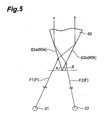
- Fig. 5 is a schematic diagram of an example of a prism disposed in a second region
- Fig. 6 is a diagram illustrating an optical path deflecting plate model for explaining a method for specifying inclination angles
- Fig. 7 is a diagram illustrating an optical path deflecting plate model for explaining part of a method for specifying inclination angles
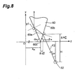
- Fig. 8 is a diagram illustrating an optical path deflecting plate model for explaining part of a method for specifying inclination angles
- Fig. 9 is a diagram illustrating an optical path deflecting plate model for explaining part of a method for specifying inclination angles
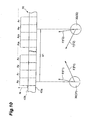
- Fig. 10 is a schematic diagram of an enlarged portion of an optical path deflecting plate of a first example
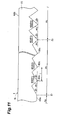
- Fig. 11 is a schematic diagram of a further enlarged portion of the optical path deflecting plate illustrated in Fig. 10 ;
- Fig. 12 is a schematic diagram of an enlarged portion of an optical path deflecting plate of a second example.
- FIG. 1 is a cross-sectional diagram illustrating schematically an embodiment of a transmissive image display device according to the present invention.
- a transmissive image display device 1 is a liquid crystal display device that comprises a transmissive image display section 10, in which polarizing plates 12, 13 are layered on the top and bottom faces of a liquid crystal cell 11, and a surface light source device 50 provided at the back of (below) the transmissive image display section 10.
- liquid crystal cell 11 and the polarizing plates 12, 13 there can be used liquid crystal cells and polarizing plates that are employed in transmissive image display devices such as conventional liquid crystal display devices and the like.
- liquid crystal cell 11 include, for instance, 90° twist TN liquid crystal display elements.
- the pair of polarizing plates 12, 13 at the top and bottom is disposed in such a manner that the respective transmission axes thereof are mutually perpendicular.
- the transmission axes of the polarizing plates 12, 13 are disposed so as to be parallel to the orientation direction of the liquid crystal molecules in the liquid crystal cell 11.
- the surface light source device 50 has a light source section 20 and an optical path deflecting plate 40 disposed at the front of (above, in Fig. 1 ) the light source section 20, i.e. separated from the light source section 20 on the side of the transmissive image display section 10.
- the light source section 20 has plural light sources 30 equidistantly disposed, with a spacing L, and positioned coplanarly with the central axis lines of the light sources 30.
- the spacing L between central axis lines of adjacent light sources 30, 30 is, for instance, 15 mm to 150 mm.
- the light sources 30 are rod-like light sources extending in a direction perpendicular to the array direction of the plural light sources 30.
- the light sources 30 are, for instance, a straight tube-like light source, such as a fluorescent light (cold cathode ray tube) or the like.
- the light sources 30 have herein a rod-like shape, a point light source such as an LED or the like may also be used.
- the plural light sources 30 are preferably disposed in a lamp box 35.
- An inner face 35a of the lamp box 35 is preferably formed as a light reflective surface.
- Light F outputted from the light sources 30 is outputted reliably thereby toward the transmissive image display section 10, so that light F from the light sources 30 can be utilized efficiently.
- the optical path deflecting plate 40 has a rear surface (main surface) 40a positioned on the side of the light source section 20, and a planar exit surface 40b disposed opposite the rear surface 40a.
- the optical path deflecting plate 40 is disposed so as to cover all the light sources 30.
- the distance d between the light sources 30 and the optical path deflecting plate 40 is, for instance, 5 mm to 50 mm.
- the distance d is the distance between the top of the light sources 30 and the rear surface 40a, as illustrated in Fig. 1 .
- the thickness of the optical path deflecting plate 40 is for instance 0.1 mm to 15 mm, preferably 0.5 mm to 10 mm, and more preferably 1 mm to 5 mm.
- the optical path deflecting plate 40 comprises a transparent material, for instance a transparent resin and/or a transparent glass.
- transparent resins include, for instance, polycarbonate resins, ABS resins (acrylonitrile-butadiene-styrene copolymer resins), methacrylic resins, MS resins (methyl methacrylate-styrene copolymer resins), polystyrene resins, AS resins (acrylonitrile-styrene copolymer resins), as well as polyolefin resins such as polyethylene, polypropylene or the like.
- a plurality of prisms 60 of triangular cross section are formed on the rear surface 40a of the optical path deflecting plate 40, at each corresponding region 41 that is a region positioned above two adjacent light sources 30, 30, between the latter, and corresponding to a region between two light sources 30, 30.
- the plural prisms 60 formed on the corresponding regions 41 have mirror symmetry (left-right symmetry in Fig. 2 ) relative to a central position between both light sources 30, 30, i.e. relative to a hypothetical plane P that is perpendicular to the exit surface 40b at a position L/2 from a light source 31 to a light source 32.
- Fig. 2 is a schematic diagram of an enlarged portion of the optical path deflecting plate.
- Fig. 2 illustrates as well two light sources 30, 30.
- the latter will be referred to hereafter as light sources 31, 32, with light F1 denoting light F outputted by the light source 31 and light F2 denoting light F outputted by the light source 32.
- each prism 60 is configured in such a manner that the orientations of light F1 and F2 from the two light sources 31, 32 are changed into the direction of the normal line N of the exit surface 40b by specifying the inclination angles ⁇ , ⁇ by which two inclined surfaces 60a, 60b of the prism 60 are tilted relative to the exit surface 40b.
- the prisms 60 include first-type prisms (first prisms) 61, and second-type prisms (second prisms) 62.
- the second-type prisms 62 are disposed at a region that includes the central position of the corresponding regions 41, while the first-type prisms 61 are disposed at regions on both sides of the region at which the second-type prisms 62 are disposed. Therefore, the corresponding regions 41 have first and third regions 41A, 41C, in which plural first-type prisms 61 are disposed, and a second region 41B, flanked by the first and third regions 41A, 41C, in which second-type prisms 62 are disposed.
- Fig. 3 is a schematic diagram of an example of a prism disposed in a first region.
- Fig. 4 is a schematic diagram of an example of a prism disposed in the third region.
- Fig. 5 is a schematic diagram of an example of a second prism.
- a first prism 61 is configured in such a manner so as to change the orientation of light from the closest light source, among the lights F1 and F2 from two light sources 31, 32, into the direction of the normal line N, through refraction at one of the inclined surfaces among the two inclined surfaces 61a, 61b of the prism 61, and so as to change the orientation of light F from the other light source into the direction of the normal line N, through total reflection inside the prism 61. That is, total reflection takes place only at one of the two inclined surfaces 61a, 61 b of the prism 61.
- the prism 61 is respectively disposed in the first and third regions 41A, 41C.
- the prism 61 When the prism 61 is disposed in the first region 41A, the prism 61 refracts light F1 from the light source 31, among both light sources 31, 32, at the inclined surface (first inclined surface) 61b of the prism 61, changing thereby the orientation of light F1 into the direction of the normal line N, and refracts light F2 from the light source 32 at the inclined surface 61b, towards the inclined surface (second inclined surface) 61a (60a), so that the refracted light is totally reflected thereafter at the inclined surface 61a, changing thereby the orientation of light F2 into the direction of the normal line N, as illustrated in Fig. 3 .
- the prism 61 When the prism 61 is disposed in the third region 41C, the prism 61 refracts light F2 from the light source 32, among both light sources 31, 32, at the inclined surface (first inclined surface) 61a of the prism 61, changing thereby the orientation of light F2 into the direction of the normal line N, and refracts light F1 from the light source 31. at the inclined surface 61a, towards the inclined surface (second inclined surface) 61b, so that the refracted light is totally reflected thereafter at the inclined surface 61b, changing thereby the orientation of light F1 into the direction of the normal line N, as illustrated in Fig. 4 .
- the second-type prisms 62 refract light F1 from the light source 31 at an inclined surface (third inclined surface) 62a, directing light F1 toward an inclined surface (fourth inclined surface) 62b at which light F1 is totally reflected, changing thereby the orientation of light F 1 into the direction of the normal line N; and refract light F2 from the light source 32 at the inclined surface 62b, towards the inclined surface 62a, so that the refracted light is totally reflected thereafter at the inclined surface 62a, changing thereby the orientation of light F2 into the direction of the normal line N.
- Total reflection takes place as a result on the two inclined surfaces 62a, 62b constituting the prism 62.
- the shape of the plural prisms 60 is determined by specifying the inclination angles ⁇ , ⁇ of the two inclined surfaces 60a, 60b constituting each prism 60.
- An example of a method for specifying the inclination angles ⁇ , ⁇ is explained next with reference to Figs. 6 to 9 .
- Fig. 6 is a diagram illustrating an optical path deflecting plate model for explaining a method for specifying the inclination angles ⁇ , ⁇ .
- a z-axis is defined by a straight line joining plural prism apexes 60c
- a y-axis corresponds to the axis of the direction of the normal line N passing through the center of the light source 31
- an origin O is the point at which the z-axis and the y-axis intersect each other.
- n denotes the refractive index of the optical path deflecting plate 40
- H denotes the distance from the origin O to the center of the light source 31.
- a prism 60 m (m is an integer equal to or greater than 1) is the prism 60 whose inclination angles ⁇ , ⁇ are to be specified.
- Prisms 60 m-1 , 60 m+1 are thus the prisms on the two sides of the prism 60.
- the inclination angles ⁇ , ⁇ and the positions on the z-axis of the prism apexes of the prisms 60 m , 60 m-1 , 60 m+1 are differentiated by means of the subindices m, m-1, m+1 corresponding to respective prisms 60 m , 60 m-1 , 60 m+1 , as illustrated in Fig. 6 .
- the inclination angle ⁇ has a positive direction in the clockwise direction while the inclination angle ⁇ has a positive direction in the counterclockwise direction as illustrated in Fig. 6 .
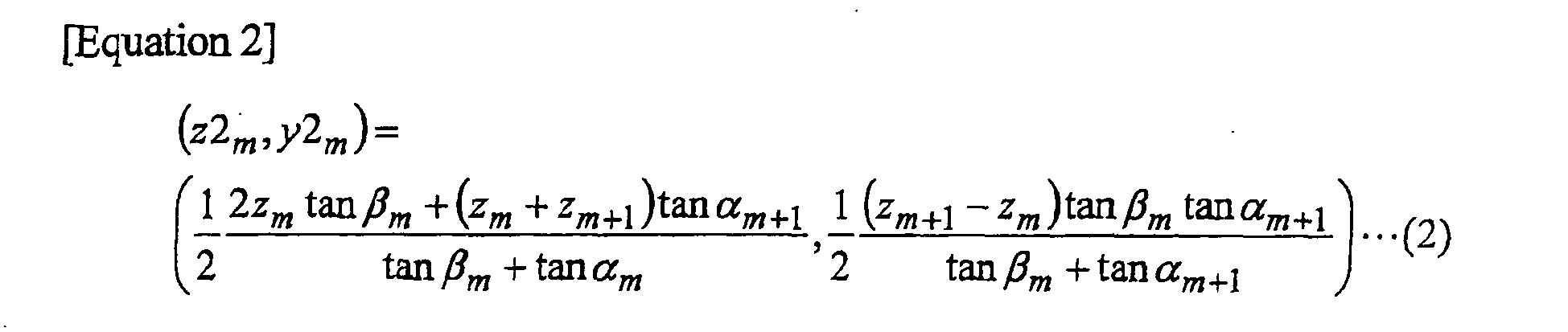
- the center points p1, p2 of the inclined surfaces 60a, 60b of the prism 60 m correspond to the positions at which the orientations of the lights F1, F2 from the light sources 31, 32 are ultimately changed into the direction of the normal line N.
- the point p1, of coordinates (z1 m , y1 m ), and the point p2, of coordinates (z2 m , y2 m ), are represented by equations (1) and (2) below.
- the conditions that the inclination angles ⁇ m , ⁇ m must satisfy when the prism 60 m is a first-type prism 61 or a second-type prism 62 are represented by a combination of refractive index conditions and total reflection conditions for three cases, as follows.
- Figs. 7 to 9 are diagrams for explaining a method for specifying inclination angles ⁇ m , ⁇ m in accordance with a method of modifying the optical paths of light F1 or light F2, by way of the prism 60 m , for each of the cases (i) to (iii) above.
- the case in which the direction of light F1 from the light source 31, as illustrated in Fig. 7 , is changed into the direction of the normal line N through refraction at the inclined surface 60b corresponds to a case where the prisms 61 are provided in the first region 41A.
- a case where the prisms 61 are disposed in the third region 41C is described later.
- ⁇ z ⁇ m correction terms for correcting, relative to the z-axis direction and the y-axis
- ⁇ z ⁇ m , ⁇ H ⁇ m that appear in equations (9) and (10) are correction terms for correcting, relative to the z-axis direction and the y-axis direction, the offset between the position of the prism apex 60c and the incidence position of light F2 on the prism 60 m that results from ultimately changing the orientation of light F2 into the direction of the normal line N at the position of the point p1, as illustrated in Fig. 8 .
- ⁇ z ⁇ m , ⁇ H ⁇ m are correction terms for correcting, relative to the z-axis direction and the y-axis direction, the offset between the incidence position of light F1 on the prism 60 and the position of the prism apex 60c that results from ultimately changing the orientation of light F1 into the direction of the normal line N at the position of the point p2, as illustrated in Fig. 9 .
- the term ⁇ z ⁇ m is positive in the direction of the arrow denoted by a broken line in Fig. 9 , i.e. in the negative direction of the z-axis.
- the change in orientation of light F1 and light F2 effected by the prisms 61 disposed in the first region 41A can be realized by combining the instances of Fig. 7 and Fig. 8 .
- the inclination angle (second inclination angle) ⁇ m , and the inclination angle (first inclination angle) ⁇ m are specified so as to satisfy simultaneously equations (3) to (6) and equations (7) to (10).
- the change in orientation of light F1 and light F2 effected by the prisms 62 disposed in the second region 41B can be realized by combining the instances of Fig. 8 and Fig. 9 .
- the inclination angle (third inclination angle) ⁇ m , and the inclination angle (fourth inclination angle) ⁇ m are specified so as to satisfy simultaneously equations (7) to (10) and equations (11) to (14).
- the third region 41C is a mirror image of the first region 41A, and hence the values of the inclination angles ⁇ m , ⁇ m are herein the reverse of those specified for the prisms 61 disposed in the first region 41A. That is, the inclination angle (first inclination angle) ⁇ m , and the inclination angle (second inclination angle) ⁇ m of each prism 61 positioned at the third region 41C are the inclination angle ⁇ and the inclination angle ⁇ of the corresponding prism 61 in the first region 41A.
- the boundary position between the first and second regions 41A, 41B, or the boundary position between the second and third regions 41B, 41C are determined in such a manner that the local brightness angular distributions of light issuing from the exit surface 40b are connected as smoothly as possible.
- the inclination angles ⁇ , ⁇ calculated using the above equations (3) to (14) can accommodate a given error tolerance, for instance about ⁇ 3°.
- the inclination angles ⁇ , ⁇ of respective prisms 60 to be formed on the corresponding regions 41 are calculated using equations (3) to (14).
- the optical path deflecting plate 40 may be obtained by forming prisms 60, having the calculated inclination angles ⁇ , ⁇ , by preparing a plate-like body comprising a transparent material, the front and reverse faces of which are both planar, and by milling predetermined positions on the reverse face, for instance by way of a micromachining technology.
- light F 1 and light F2 outputted from two adjacent light sources 31, 32, among a plurality of light sources 30, are mainly incident on corresponding regions 41 at a position between two adjacent light sources 31, 32, above the latter.
- Each corresponding region 41 is formed by a plurality of prisms 60. Also, a plurality of first-type prisms 61, among a plurality of prisms 60, is formed on the first and third regions 41A,41C of the each corresponding region 41, and a plurality second-type prisms 62 is formed on the second region 41B.
- the first- and second-type prisms 61, 62 are configured in such a manner that light F1 and light F2 from the light sources 31, 32 exit both in the direction of the normal line N. Hence, light F exits from the optical path deflecting plate 40 oriented in the direction of the normal line N, across the entire exit surface 40b.
- the brightness of light F issuing from the optical path deflecting plate 40 i.e. light F issuing from the surface light source device 50, becomes uniform as a result. Brightness increases because there is less light issuing at a tilt relative to the direction of the normal line N.
- the angle formed between the direction of the normal line N and the direction of light F from the light sources 30 directed at the prisms 60 increases as does the distance that separates the light sources 30 and the prisms 60 formed on the rear surface 40a of the optical path deflecting plate 40, in the direction perpendicular to the direction of the normal line N, which as a result makes it more difficult to change the orientation of light F into the direction of the normal line N by refraction upon incidence on the prisms 60.
- the orientation of light F (F1 or F2) from a close light source 30 (31 or 32) is changed into the direction of the normal line N through refraction upon incidence of light F at the prisms 61 disposed in the closer first and third regions 41A, 41C directly above the light sources 31, 32, while light F (F2 or F1) from a distant light source 30 (32 or 31) is changed into the direction of the normal line N through total refraction in the prisms 61.
- the prisms 62 disposed in the second region 41B changes the directions of light F1, F2 from the light sources 31, 32 into the direction of the normal line N, through total reflection in the prisms 62.
- the orientation of light F from each light source 30 can be reliably changed into the direction of the normal line N.
- uniform high-brightness light F can issue, as described above, from the optical path deflecting plate 40 used in the surface light source device 50.
- the transmissive image display device 1 which is configured in such a manner that light F from the surface light source device 50 is incident on the transmissive image display section 10 as illustrated in Fig. 1 , uniform high-brightness light F strikes thus the transmissive image display section 10, making it possible to display sharper images, of uniform brightness, across an entire screen.
- the trough portions between two adjacent prisms 60, 60 are located directly above the light sources 30 (31, 32), as illustrated in Fig. 2 .
- the shapes located directly above the light sources 30 may be, for instance, planar.
- the prism apexes 60c may be positioned directly above the light sources 30.
- the above first- and second-type prisms 61, 62 may be disposed in the same way at regions of the corresponding regions 41 excluding planar regions directly above the light sources.
- the optical path deflecting plate 40 has preferably dispersed therein a diffusive material.
- the light sources 30, moreover, have ordinarily a certain width.
- the corresponding regions 41 are not limited to being positioned between the central axis lines of adjacent light sources 30, 30, as described above, but may also be offset to the left or right of the regions between the central axis lines, such that the width of the corresponding regions 41 need not match the length between central axis lines.
- the plural prisms 60 provided in the corresponding regions 41 are symmetrical with respect to the plane P illustrated in Fig. 2 .
- the first- and second-type prisms 61, 62 are disposed in the above-described positional relationship, the number of prisms and the like may differ on both sides of the plane P.
- optical path deflecting plate is explained next by way of example.
- Fig. 10 is a schematic diagram illustrating the constitution of an optical path deflecting plate of a first example.
- An optical path deflecting plate 70 is used in the surface light source device 50 in place of the optical path deflecting plate 40 illustrated in Fig. 1 .
- Fig. 10 illustrates an enlarged portion of the optical path deflecting plate 70 of the first example.
- Fig. 10 illustrates also two adjacent light sources 30, 30, among the plural light sources 30 of the surface light source device 50.
- the plural light sources 30 in the surface light source device 50 are all fluorescent lamps.
- the spacing L between two adjacent light sources 30, 30, among the plural light sources 30, is 30 mm. As was the case in the above-described embodiment, to differentiate the two light sources 30, 30, the latter will be referred to as light sources 31, 32 in the explanation that follows.
- the optical path deflecting plate 70 differs mainly from the optical path deflecting plate 40 illustrated in Fig. 1 in that now the rear surface 40a opposing the light sources 31, 32 has regions A 0 that include the positions directly above the light sources 31, 32, and 29 regions (unit regions) A 1 to A 29 between the region A 0 directly above the light source 31 and the region A 0 directly above the light source 32.
- the optical path deflecting plate 70 is explained next focusing on this difference.
- the optical path deflecting plate 70 comprises a transparent resin having a refractive index of 1.57.
- the thickness of the optical path deflecting plate 70 is 2 mm.
- the surface of exit surface 40b of the optical path deflecting plate 70, i.e. the surface on the front side, is planar all over.
- the regions A 0 to A 29 on the rear surface 40a of the optical path deflecting plate 70 each have a width of 1000 ⁇ m.
- the centers in the width-direction of each region A 0 are positioned directly above the center axis lines of the corresponding light sources 31, 32.
- the corresponding region 41 in the optical path deflecting plate 70 therefore, comprises half the region A 0 , on the side of the region A 1 , above the light source 31, regions A 1 to A 29 , and half the region A 0 , on the side of the region A 29 , above the light source 32.
- the corresponding region 41 is explained herein as the region between the center axis lines of the light sources 31, 32.
- the latter have a width of their own, and hence the region comprising the region A 0 to the region A 29 can be considered as the corresponding region 41.
- the corresponding region 41 can be divided into 30 regions.
- the region A 0 of the rear surface 40a has a planar surface.
- the spacing between adjacent prisms 60 i.e. the distance 1 between prism apexes 60c, is 50 ⁇ m.
- the distance H between the light sources 31, 32 and the optical path deflecting plate 70 is 20 mm.
- the 20 prisms 60 within each region A 1 to A 29 have identical cross-sectional shape. That is, the inclination angles ⁇ , ⁇ of the inclined surfaces 60a, 60b of each prism 60, within a respective region A 1 to A 29 , are identical. As illustrated in Fig. 11 , the boundaries of the regions A 1 to A 29 are positioned at the prism apexes 60c, and hence a prism 60 having the prism apex 60c at a boundary position straddles two adjacent regions A i , A i+1 . Herein, the prism 60 at the boundary position is counted as belonging to the region farther from the light source 31, i.e. the region A i+1 .
- the inclination angles ⁇ m , ⁇ m formed by the exit surface 40b and the two inclined surfaces 60a,60b constituting the prisms 60 within each region A 1 to A 29 are calculated by combining equations (3) to (14).
- Z m is calculated as the boundary position Z i of two adjacent regions A i-1 , A i (i is any integer from 1 to 29). The results of the calculation are as given in Table 1.
- the region comprising regions A 1 to A 5 is the first region 41A.
- the region comprising regions A 6 to A 25 is the second region 41B.
- each region A 1 to A 29 twenty prisms 60 are disposed within each region A 1 to A 29 .
- the width of each region A 1 to A 29 is about 1000 ⁇ m
- the prisms 60 within the regions A 1 to A 5 and the regions A 26 to A 29 function as first-type prisms 61
- the prisms within the regions A 6 to A 25 function as second-type prisms 62.
- the angle ⁇ 1 is used as the inclination angle of the inclined surface that connects the region A 0 above the light source 31 and the prism 60, within the region A 1 , that is adjacent to the region A 0 as illustrated in Fig. 11 .
- the angle ⁇ 30 and not ⁇ 30 is used as the inclination angle of the inclined surface that connects the region A 0 above the light source 32 and the prism 60, within the region A 29 , that is adjacent to the region A 0 .
- optical path deflecting plate 70 having the above constitution, light F1, F2 outputted from two adjacent light sources 31, 32, among plural light sources 30, is incident on the regions A 0 to A 29 between and above two adjacent light sources 31,32.
- Light F1, F2 from the light sources 31, 32 can easily be oriented in the direction of the normal line N, and be made incident on the region A 0 directly above the light source 31 and the region A 0 directly above the light source 32. Since the rear surface 40a at each region A 0 has a planar surface, light F1, F2 striking the respective regions A 0 issues from the exit surface 40b in the direction of the normal line N of the optical path deflecting plate 40.
- the regions A 1 to A 5 , A 6 to A 25 and A 26 to A 29 correspond respectively to the above-described first to third regions 41 A to 41C, where the first-type prisms 61 and second-type prisms 62 are disposed.
- the first- and second-type prisms 61, 62 are such that light F1, F2 from the light sources 31, 32 exit both in the direction of the normal line N.
- the orientations of light F1, F2 striking the portion comprising the regions A 1 to A 29 are changed into the direction of the normal line N.
- the optical path deflecting plate 40 therefore, light F exits from the optical path deflecting plate 70 oriented in the direction of the normal line N, across substantially the entire exit surface 70b.
- the brightness of the light F issuing from the optical path deflecting plate 70 is made uniform as a result, while brightness is further enhanced as there is less light issuing at a tilt relative to the direction of the normal line N.
- the optical path deflecting plate 70 there are disposed 20 prisms 60 within each region A 1 to A 29 , and hence the number of prisms 60 provided in the optical path deflecting plate 70 can be increased.
- the orientation of light F is changed at each prism 60, and thus the orientation of light F can be aligned in the direction of the normal line N more easily by way of the optical path deflecting plate 70.
- the disposed prisms 60 have identical cross-sectional shapes in each region A 1 to A 29 , and hence the prisms 60 in each region A 1 to A 29 can be manufactured under identical conditions even when increasing thus the number of prisms 60. This allows, as a result, shortening the time required for manufacturing the optical path deflecting plate 70 vis-à-vis a case where the manufacture of a same number of prisms 60 involves specifying individual cross-sectional shapes for adjacent prisms 60.
- uniform high-brightness light F strikes the transmissive image display section 10, making it possible, as a result, to display sharper images of uniform brightness, across an entire screen, in the transmissive image display device 1.
- Fig. 12 is a schematic diagram illustrating the constitution of an optical path deflecting plate of a second example.
- An optical path deflecting plate 75 is used in the surface light source device 50 in place of the optical path deflecting plate 40 illustrated in Fig. 1 .
- Fig. 12 illustrates an enlarged portion of the optical path deflecting plate 75 of the second example.
- Fig. 12 illustrates also two adjacent light sources 30, 30, among the plural light sources 30 of the surface light source device 50.
- the plural light sources 30 in the surface light source device 50 are all fluorescent lamps.
- the spacing L between two adjacent light sources 30, 30, among the plural light sources 30, is 30 mm. As was the case in the above-described embodiment, to differentiate the two light sources 30, 30, the latter will be referred to as light sources 31, 32 in the explanation that follows.
- the optical path deflecting plate 75 has regions A 0 above respective light sources 31, 32.
- the optical path deflecting plate 75 differs mainly from the optical path deflecting plate 70 of the first example in that now there are formed 28 prisms 60 between a region A 0 above the light source 31 and a region A 0 above the light source 32, with a spacing between prism apexes of 1000 ⁇ m.
- the optical path deflecting plate 75 differs from the optical path deflecting plate 70 in that the prisms 60 are formed having prism apexes at the boundary positions z i of adjacent regionsA i-1 , A i in the optical path deflecting plate 70.
- Angles ⁇ 30 , ⁇ 30 are the reverse of ⁇ 1 , ⁇ 1 .
- the value of ⁇ 1 is used as the inclination angle of the inclined surface that connects the region A 0 above the light source 31, and the prism 60 that is adjacent to the region A 0 , and the value of ⁇ 1 is not used, as illustrated in Fig. 12 .
- the angle ⁇ 30 and not ⁇ 30 is used as the inclination angle of the inclined surface that connects the region A 0 above the light source 32 and the prism 60 that is adjacent to the region A 0 on the side of the light source 31.
- the optical path deflecting plate 75 having the above constitution has two regions A 0 , A 0 above the light sources 31, 32, respectively.
- light F1, F2 outputted from the region A 0 above the light source 31 and the region A 0 above the light source 32 exits in the direction of the normal line N.
- first-type prisms 61 and second-type prisms 62 are disposed at the regions between the two regions A 0 and A 0 , and hence the orientations of light F1, F2 from the two adjacent light sources 31, 32 can both be changed into the direction of the normal line N, as is the case in the optical path deflecting plate 40 illustrated in Fig. 1 .
- optical path deflecting plate, surface light source device and transmissive image display device of the present invention are not meant to limit the invention in any way.
- equations including the correction terms ⁇ z ⁇ m , ⁇ H ⁇ m , ⁇ z ⁇ m , ⁇ H ⁇ m are used for determining the inclination angles ⁇ m , ⁇ m .
- the pitch 1 between two adjacent prisms 60 is small enough relative to H and L, for instance no greater than about 1/10, the above correction terms need not be used.
- the prisms 60 are formed by milling of the rear surface 40a, the prisms 60 may also, for instance, be molded integrally into the rear surface 40a.
- one corresponding region 41 there may be provided one second-type prism 62, and one first-type prism 61 each at both sides of the second-type prism 62, depending on the length thereof in the width direction of the corresponding region 41.
- the surface light source device 50 has been exemplified as being used in the transmissive image display device 1.
- the use of the surface light source device 50 is not limited to the transmissive image display device 1.
- the use of the optical path deflecting plates 40, 70, 75 is not limited to the surface light source device 50.
Landscapes
- Physics & Mathematics (AREA)
- General Physics & Mathematics (AREA)
- Optics & Photonics (AREA)
- Nonlinear Science (AREA)
- Mathematical Physics (AREA)
- Chemical & Material Sciences (AREA)
- Crystallography & Structural Chemistry (AREA)
- Planar Illumination Modules (AREA)
- Optical Elements Other Than Lenses (AREA)
- Liquid Crystal (AREA)
Abstract
Description
- The present invention relates to an optical path deflecting plate, a surface light source device and a transmissive image display device.
- Widely known transmissive image display devices include devices having a direct-type surface light source device disposed on the rear face of a transmissive image display section such as a transmissive liquid crystal cell or the like. Known such surface light source devices include devices comprising plural light sources arrayed in-plane, spaced apart from each other, and a prism member (optical path deflecting plate) which is disposed in front of the plural light sources and changes the orientation of the light from the light sources and outputting the light (Japanese Patent Application Laid-open No.
H07-141908 - In the optical path deflecting plate disclosed in Japanese Patent Application Laid-open No.
H07-141908 - It is thus an object of the present invention to provide an optical path deflecting plate, a surface light source device and a transmissive image display device that allow ensuring uniform high brightness.
- The optical path deflecting plate of the present invention is an optical path deflecting plate disposed separated from a plurality of light sources that are arrayed spaced apart from each other, for changing an orientation of light from the plurality of light sources and outputting the light, comprising: a main surface on which light from the plurality of light sources is incident; and a planar exit surface which is disposed opposite the main surface, and from which there exits light from the plurality of light sources that is incident through the main surface; wherein the main surface comprises a plurality of prisms provided in each region of the main surface that corresponds to a region between two adjacent light sources; the each corresponding region has first to third regions in an array direction of the plurality of light sources; at least one first prism, among the plurality of prisms, is disposed at the first and third regions; at least one second prism, among the plurality of prisms, is disposed at the second region; the first prism changes the orientation of light from the light source that is closer to the first prism, among the two adjacent light sources, into a normal line direction of the exit surface, through refraction upon incidence on the first prism, and changes the orientation of light from the light source that is farther from the first prism, among the two adjacent light sources, into the normal line direction, through total reflection in the first prism; and the second prism changes the orientation of light from the two adjacent light sources into the normal line direction through total reflection in the second prism.
- In the above constitution, the first to third regions in respective corresponding regions of the main surface are disposed in the order of first to third regions in the array direction. Therefore, the first region is closer to one of the two adjacent light sources, the third region is closer to the other of the two adjacent light sources, while the second region is positioned between the first and the third regions.
- In the first and third regions there is provided at least one first prism among the plurality of prisms, whereby the orientation of light from the closer light source is changed into the normal line direction through refraction upon incidence on the prism, while the orientation of light for the farther light source is changed into the normal line direction through total reflection in the prism. Although the angle formed between the normal line direction and the direction of the light directed from the farther light source toward the prisms disposed in the first and third regions tends to become larger, the orientation of the light can still be changed reliably into the normal line direction thanks to total reflection, as in the above-described first prism. Also, at least one second prism, among the plurality of prisms, is disposed at the second region. Therefore, the orientation of the light of both adjacent light sources is changed into the normal line direction through internal reflection in the prisms provided in the second region. The second region is positioned between the first and third regions. Accordingly, although the angle formed between the normal line direction and the direction of the light directed from the light sources toward the prisms disposed in the second region tends to become larger, the orientation of the light from both light sources can still be changed reliably into the normal line direction thanks to total reflection in the prisms, as in the above-described second prism.
- Therefore, all the light that strikes the corresponding regions, from both light sources that correspond to respective corresponding regions, exits in the normal line direction of the exit surface. The brightness of the light issuing through the exit surface is made uniform as a result Yet higher brightness can thus be realized since the light striking the corresponding regions exits thus more reliably in the normal line direction.
- Preferably, first and second inclination angles, formed by the exit surface and first and second inclined surfaces constituting the first prism, are specified in such a manner that the first inclined surface refracts light from the light source that is closer to the first prism, among the two adjacent light sources, into the normal line direction, the first inclined surface refracts light from the light source that is farther from the first prism, among the two adjacent light sources, towards the second inclined surface, and the second inclined surface totally reflects the refracted light into the normal line direction; and wherein third and fourth inclination angles, formed by the exit surface and third and fourth inclined surfaces constituting the second prism, are specified in such a manner that the third inclined surface refracts light from the light source on the side of the third inclined surface, among the two adjacent light sources, towards the fourth inclined surface, the fourth inclined surface totally reflects the refracted light into the normal line direction; the fourth inclined surface refracts light from the light source on the side of the fourth inclined surface, among the two adjacent light sources, towards the third inclined surface, and the third inclined surface totally reflects the refracted light into the normal line direction.
- By specifying the first and second inclination angles as described above, the orientation of the light from the closer light source, among both light sources corresponding to respective corresponding regions, is changed into the normal line direction through refraction at the first inclined surface of the first prism, while the orientation of the light from the farther light source, among the two light sources, is changed into a direction toward the second inclined surface, through refraction upon incidence of the first prism, and is then changed into the normal line direction through total reflection at the second inclined surface. The orientation of the light from both light sources is thus changed by the first prism into the normal line direction. By specifying the third and fourth inclination angles as described above, light from both light sources corresponding to respective corresponding regions, strikes the second prism via the third inclined surface and the fourth inclined surface, whereafter the orientation of the light is changed into the normal line direction through total reflection at the fourth inclined surface and the third inclined surface. The orientation of the light from both light sources is thus changed by the second prism into the normal line direction.
- Preferably, the plurality of prisms provided in the corresponding region is symmetrical with respect to a plane perpendicular to the exit surface, at a central position between the two adjacent light sources.
- In this case, there may be specified a prism shape for half the regions in a corresponding region, which allows shortening the time required for manufacturing the optical path deflecting plate.
- Preferably, moreover, the first to third regions each have a plurality of unit regions, a plurality of the first prisms of identical cross-sectional shape is provided at each of the plurality of unit regions of the first and third regions, and a plurality of the second prisms of identical cross-sectional shape is provided at each of the plurality of unit regions of the second region.
- In this case, a plurality of first prisms of identical cross-sectional shape is respectively provided in each unit region of the first and third regions, while a plurality of second prisms of identical cross-sectional shape is provided in each unit region of the second region. This allows manufacturing the prisms in each unit region under identical conditions, and allows changing light orientation in more prisms. Hence, the orientation of the light can be aligned in the normal line direction more easily.
- The surface light source device according to the present invention comprises a plurality of light sources arrayed spaced apart from each other, and the above-described optical path deflecting plate according to the invention, disposed separated from the plurality of light sources.
- In this case, light outputted by each of the light sources passes through the optical path deflecting plate and exits through the exit surface of the optical path deflecting plate. Thereupon, when light from two adjacent light sources among the plural light sources strikes corresponding regions of the optical path deflecting plate that correspond to the two light sources, the light is outputted in the normal line direction of the exit surface, as described above. The above surface light source device, therefore, allows outputting uniform high-brightness light.
- Further, the transmissive image display device according to the present invention comprises the above-described surface light source device according to the present invention and a transmissive image display section disposed separated from the surface light source device, relative to an exit direction of light from the surface light source device.
- In such a transmissive image display device, thus, uniform high-brightness light outputted from the above-described surface light source device strikes the transmissive image display section. As a result, the transmissive image display section can display sharper images of uniform brightness.
- The above-described optical path deflecting plate according to the present invention allows outputting together light from two adjacent light sources in the normal line direction of an exit surface, and can thus ensure more uniform high brightness. By way of the optical path deflecting plate, the surface light source device according to the present invention allows outputting together light from two adjacent light sources in the normal line direction of an exit surface, and allows hence outputting more uniform high-brightness light. By way of the surface light source device, furthermore, the transmissive image display device according to the present invention allows more uniform high-brightness light to strike a transmissive image display section, and allows hence displaying sharper images, of uniform brightness, on the transmissive image display section.
-
Fig. 1 is a cross-sectional diagram illustrating schematically an embodiment of a transmissive image display device according to the present invention; -
Fig. 2 is a schematic diagram of an enlarged portion of an optical path deflecting plate; -
Fig. 3 is a schematic diagram of an example of a prism disposed in a first region; -
Fig. 4 is a schematic diagram of an example of a prism disposed in a third region; -
Fig. 5 is a schematic diagram of an example of a prism disposed in a second region; -
Fig. 6 is a diagram illustrating an optical path deflecting plate model for explaining a method for specifying inclination angles; -
Fig. 7 is a diagram illustrating an optical path deflecting plate model for explaining part of a method for specifying inclination angles; -
Fig. 8 is a diagram illustrating an optical path deflecting plate model for explaining part of a method for specifying inclination angles; -
Fig. 9 is a diagram illustrating an optical path deflecting plate model for explaining part of a method for specifying inclination angles; -
Fig. 10 is a schematic diagram of an enlarged portion of an optical path deflecting plate of a first example; -
Fig. 11 is a schematic diagram of a further enlarged portion of the optical path deflecting plate illustrated inFig. 10 ; and -
Fig. 12 is a schematic diagram of an enlarged portion of an optical path deflecting plate of a second example. - An embodiment of the optical path deflecting plate, surface light source device and transmissive image display device of the present invention is explained below with reference to accompanying drawings. In the drawings, identical elements are denoted with identical reference numerals, and recurrent explanations thereof are omitted. Also, the dimensional ratios in the drawings do not necessarily match those in the explanation.
-
Fig. 1 is a cross-sectional diagram illustrating schematically an embodiment of a transmissive image display device according to the present invention. A transmissiveimage display device 1 is a liquid crystal display device that comprises a transmissiveimage display section 10, in which polarizingplates liquid crystal cell 11, and a surfacelight source device 50 provided at the back of (below) the transmissiveimage display section 10. - As the
liquid crystal cell 11 and the polarizingplates liquid crystal cell 11 include, for instance, 90° twist TN liquid crystal display elements. The pair ofpolarizing plates polarizing plates liquid crystal cell 11. - The surface
light source device 50 has alight source section 20 and an opticalpath deflecting plate 40 disposed at the front of (above, inFig. 1 ) thelight source section 20, i.e. separated from thelight source section 20 on the side of the transmissiveimage display section 10. - The
light source section 20 has plurallight sources 30 equidistantly disposed, with a spacing L, and positioned coplanarly with the central axis lines of thelight sources 30. The spacing L between central axis lines of adjacentlight sources light sources 30 are rod-like light sources extending in a direction perpendicular to the array direction of the plurallight sources 30. Thelight sources 30 are, for instance, a straight tube-like light source, such as a fluorescent light (cold cathode ray tube) or the like. Although thelight sources 30 have herein a rod-like shape, a point light source such as an LED or the like may also be used. - As illustrated in
Fig. 1 , the plurallight sources 30 are preferably disposed in alamp box 35. Aninner face 35a of thelamp box 35 is preferably formed as a light reflective surface. Light F outputted from thelight sources 30 is outputted reliably thereby toward the transmissiveimage display section 10, so that light F from thelight sources 30 can be utilized efficiently. - The optical
path deflecting plate 40 has a rear surface (main surface) 40a positioned on the side of thelight source section 20, and aplanar exit surface 40b disposed opposite therear surface 40a. The opticalpath deflecting plate 40 is disposed so as to cover all thelight sources 30. The distance d between thelight sources 30 and the opticalpath deflecting plate 40 is, for instance, 5 mm to 50 mm. The distance d is the distance between the top of thelight sources 30 and therear surface 40a, as illustrated inFig. 1 . The thickness of the opticalpath deflecting plate 40 is for instance 0.1 mm to 15 mm, preferably 0.5 mm to 10 mm, and more preferably 1 mm to 5 mm. - The optical
path deflecting plate 40 comprises a transparent material, for instance a transparent resin and/or a transparent glass. Examples of transparent resins include, for instance, polycarbonate resins, ABS resins (acrylonitrile-butadiene-styrene copolymer resins), methacrylic resins, MS resins (methyl methacrylate-styrene copolymer resins), polystyrene resins, AS resins (acrylonitrile-styrene copolymer resins), as well as polyolefin resins such as polyethylene, polypropylene or the like. - As illustrated in
Fig. 2 , a plurality ofprisms 60 of triangular cross section are formed on therear surface 40a of the opticalpath deflecting plate 40, at eachcorresponding region 41 that is a region positioned above two adjacentlight sources light sources plural prisms 60 formed on the correspondingregions 41 have mirror symmetry (left-right symmetry inFig. 2 ) relative to a central position between bothlight sources exit surface 40b at a position L/2 from alight source 31 to alight source 32. -
Fig. 2 is a schematic diagram of an enlarged portion of the optical path deflecting plate.Fig. 2 illustrates as well twolight sources light sources light sources light source 31 and light F2 denoting light F outputted by thelight source 32. - As illustrated in
Fig. 2 , theplural prisms 60 are formed in such a manner that the prism apexes thereof are positioned on a same plane. As illustrated inFig. 2 , eachprism 60 is configured in such a manner that the orientations of light F1 and F2 from the twolight sources exit surface 40b by specifying the inclination angles α, β by which twoinclined surfaces prism 60 are tilted relative to theexit surface 40b. - The
prisms 60 include first-type prisms (first prisms) 61, and second-type prisms (second prisms) 62. The second-type prisms 62 are disposed at a region that includes the central position of the correspondingregions 41, while the first-type prisms 61 are disposed at regions on both sides of the region at which the second-type prisms 62 are disposed. Therefore, the correspondingregions 41 have first andthird regions type prisms 61 are disposed, and asecond region 41B, flanked by the first andthird regions type prisms 62 are disposed. - The
prisms Figs. 3 to 5 .Fig. 3 is a schematic diagram of an example of a prism disposed in a first region.Fig. 4 is a schematic diagram of an example of a prism disposed in the third region.Fig. 5 is a schematic diagram of an example of a second prism. - As illustrated in
Figs. 3 and4 , afirst prism 61 is configured in such a manner so as to change the orientation of light from the closest light source, among the lights F1 and F2 from twolight sources inclined surfaces prism 61, and so as to change the orientation of light F from the other light source into the direction of the normal line N, through total reflection inside theprism 61. That is, total reflection takes place only at one of the twoinclined surfaces prism 61. A detailed explanation follows next on instances where theprism 61 is respectively disposed in the first andthird regions - When the
prism 61 is disposed in thefirst region 41A, theprism 61 refracts light F1 from thelight source 31, among bothlight sources prism 61, changing thereby the orientation of light F1 into the direction of the normal line N, and refracts light F2 from thelight source 32 at theinclined surface 61b, towards the inclined surface (second inclined surface) 61a (60a), so that the refracted light is totally reflected thereafter at theinclined surface 61a, changing thereby the orientation of light F2 into the direction of the normal line N, as illustrated inFig. 3 . - When the
prism 61 is disposed in thethird region 41C, theprism 61 refracts light F2 from thelight source 32, among bothlight sources prism 61, changing thereby the orientation of light F2 into the direction of the normal line N, and refracts light F1 from thelight source 31. at theinclined surface 61a, towards the inclined surface (second inclined surface) 61b, so that the refracted light is totally reflected thereafter at theinclined surface 61b, changing thereby the orientation of light F1 into the direction of the normal line N, as illustrated inFig. 4 . - The second-
type prisms 62, as illustrated inFig. 5 , refract light F1 from thelight source 31 at an inclined surface (third inclined surface) 62a, directing light F1 toward an inclined surface (fourth inclined surface) 62b at which light F1 is totally reflected, changing thereby the orientation oflight F 1 into the direction of the normal line N; and refract light F2 from thelight source 32 at theinclined surface 62b, towards theinclined surface 62a, so that the refracted light is totally reflected thereafter at theinclined surface 62a, changing thereby the orientation of light F2 into the direction of the normal line N. Total reflection takes place as a result on the twoinclined surfaces prism 62. - As explained above, the shape of the
plural prisms 60, that include theprisms 61 and theprisms 62 of two types, is determined by specifying the inclination angles α, β of the twoinclined surfaces prism 60. An example of a method for specifying the inclination angles α, β is explained next with reference toFigs. 6 to 9 . -
Fig. 6 is a diagram illustrating an optical path deflecting plate model for explaining a method for specifying the inclination angles α, β. - As illustrated in
Fig. 6 , a z-axis is defined by a straight line joining plural prism apexes 60c, a y-axis corresponds to the axis of the direction of the normal line N passing through the center of thelight source 31, and an origin O is the point at which the z-axis and the y-axis intersect each other. Also, n denotes the refractive index of the opticalpath deflecting plate 40, and H denotes the distance from the origin O to the center of thelight source 31. A prism 60m (m is an integer equal to or greater than 1) is theprism 60 whose inclination angles α, β are to be specified.Prisms prism 60. The inclination angles α, β and the positions on the z-axis of the prism apexes of theprisms respective prisms Fig. 6 . Also, the inclination angle α has a positive direction in the clockwise direction while the inclination angle β has a positive direction in the counterclockwise direction as illustrated inFig. 6 . - The center points p1, p2 of the
inclined surfaces prism 60m correspond to the positions at which the orientations of the lights F1, F2 from thelight sources 
- The conditions that the inclination angles αm, βm must satisfy when the
prism 60m is a first-type prism 61 or a second-type prism 62 are represented by a combination of refractive index conditions and total reflection conditions for three cases, as follows. - (i) Change of the orientation of light F1 from the
light source 31 into the direction of the normal line N, through refraction accompanying incidence on theprism 60, as illustrated inFig. 7 ; - (ii) Change of the orientation of light F2 from the
light source 32 into the direction of the normal line N, through total reflection at theinclined surface 60a, as illustrated inFig. 8 ; and - (iii) Change of the orientation of light F1 from the
light source 31 into the direction of the normal line N, through total reflection at theinclined surface 60b, as illustrated inFig. 9 . -
Figs. 7 to 9 are diagrams for explaining a method for specifying inclination angles αm, βm in accordance with a method of modifying the optical paths of light F1 or light F2, by way of theprism 60m , for each of the cases (i) to (iii) above. The case in which the direction of light F1 from thelight source 31, as illustrated inFig. 7 , is changed into the direction of the normal line N through refraction at theinclined surface 60b corresponds to a case where theprisms 61 are provided in thefirst region 41A. A case where theprisms 61 are disposed in thethird region 41C is described later. - The necessary conditions for achieving (i) above are given by equations (3) to (6) below, wherein θm denotes the angle formed between the y-axis and light F1 incident on the
prism 60m, as illustrated inFig. 7 .


light F 1 and the position of theprism apex 60c that results from taking, as the position of the point p2, the position at which the orientation of light F1 is ultimately changed into the direction of the normal line N, as illustrated inFig. 7 . - The necessary conditions for achieving (ii) above are given by equations (7) to (10) below, wherein θm is defined as in (i), and ξm denotes the angle formed between the direction of the normal line N (y-axis direction) and light F2 from the
light source 32 that strikes theprism 60m.


- The terms Δzα m, ΔHα m that appear in equations (9) and (10) are correction terms for correcting, relative to the z-axis direction and the y-axis direction, the offset between the position of the
prism apex 60c and the incidence position of light F2 on theprism 60m that results from ultimately changing the orientation of light F2 into the direction of the normal line N at the position of the point p1, as illustrated inFig. 8 . - Further, the necessary conditions for achieving (iii) above are given by equations (11) to (14) below, wherein θm and ξm are defined as in (i), (ii).


- The terms Δzβ m, ΔHβ m are correction terms for correcting, relative to the z-axis direction and the y-axis direction, the offset between the incidence position of light F1 on the
prism 60 and the position of theprism apex 60c that results from ultimately changing the orientation of light F1 into the direction of the normal line N at the position of the point p2, as illustrated inFig. 9 . The term Δzβ m is positive in the direction of the arrow denoted by a broken line inFig. 9 , i.e. in the negative direction of the z-axis. - As illustrated in
Fig. 3 , the change in orientation of light F1 and light F2 effected by theprisms 61 disposed in thefirst region 41A can be realized by combining the instances ofFig. 7 andFig. 8 . Accordingly, the inclination angle (second inclination angle) αm, and the inclination angle (first inclination angle) βm, for the case where theprism 60m is aprism 61 in thefirst region 41A, are specified so as to satisfy simultaneously equations (3) to (6) and equations (7) to (10). - Furthermore, as illustrated in
Fig. 5 , the change in orientation of light F1 and light F2 effected by theprisms 62 disposed in thesecond region 41B can be realized by combining the instances ofFig. 8 andFig. 9 . Accordingly, the inclination angle (third inclination angle) αm, and the inclination angle (fourth inclination angle) βm, for the case where theprism 60m is aprism 62, are specified so as to satisfy simultaneously equations (7) to (10) and equations (11) to (14). - The
third region 41C is a mirror image of thefirst region 41A, and hence the values of the inclination angles αm, βm are herein the reverse of those specified for theprisms 61 disposed in thefirst region 41A. That is, the inclination angle (first inclination angle) αm, and the inclination angle (second inclination angle) βm of eachprism 61 positioned at thethird region 41C are the inclination angle β and the inclination angle α of thecorresponding prism 61 in thefirst region 41A. - The boundary position between the first and
second regions third regions exit surface 40b are connected as smoothly as possible. - The above inclination angles α, β of the prisms 60 (61 or 62) respectively disposed in the first to
third regions 41A to 41C, are preferably calculated up to half the regions (i.e. regions up to z=L/2) in the z-axis direction of thecorresponding region 41, using reverse values of the inclination angles α, β, as the respective α, β values of the regions in the remaining half, since doing so allows omitting part of the calculation. The inclination angles α, β calculated using the above equations (3) to (14) can accommodate a given error tolerance, for instance about ±3°. - In the manufacture of the optical
path deflecting plate 40, the inclination angles α, β ofrespective prisms 60 to be formed on the correspondingregions 41 are calculated using equations (3) to (14). The opticalpath deflecting plate 40 may be obtained by formingprisms 60, having the calculated inclination angles α, β, by preparing a plate-like body comprising a transparent material, the front and reverse faces of which are both planar, and by milling predetermined positions on the reverse face, for instance by way of a micromachining technology. - In the surface
light source device 50 using the opticalpath deflecting plate 40 having the above constitution,light F 1 and light F2 outputted from two adjacentlight sources light sources 30, are mainly incident on correspondingregions 41 at a position between two adjacentlight sources - Each
corresponding region 41 is formed by a plurality ofprisms 60. Also, a plurality of first-type prisms 61, among a plurality ofprisms 60, is formed on the first andthird regions corresponding region 41, and a plurality second-type prisms 62 is formed on thesecond region 41B. - The first- and second-
type prisms light sources path deflecting plate 40 oriented in the direction of the normal line N, across theentire exit surface 40b. The brightness of light F issuing from the opticalpath deflecting plate 40, i.e. light F issuing from the surfacelight source device 50, becomes uniform as a result. Brightness increases because there is less light issuing at a tilt relative to the direction of the normal line N. - Ordinarily, the angle formed between the direction of the normal line N and the direction of light F from the
light sources 30 directed at theprisms 60 increases as does the distance that separates thelight sources 30 and theprisms 60 formed on therear surface 40a of the opticalpath deflecting plate 40, in the direction perpendicular to the direction of the normal line N, which as a result makes it more difficult to change the orientation of light F into the direction of the normal line N by refraction upon incidence on theprisms 60. - In the optical
path deflecting plate 40 of the present embodiment, by contrast, the orientation of light F (F1 or F2) from a close light source 30 (31 or 32) is changed into the direction of the normal line N through refraction upon incidence of light F at theprisms 61 disposed in the closer first andthird regions light sources prisms 61. Theprisms 62 disposed in thesecond region 41B changes the directions of light F1, F2 from thelight sources prisms 62. In the opticalpath deflecting plate 40, therefore, the orientation of light F from eachlight source 30 can be reliably changed into the direction of the normal line N. As a result, uniform high-brightness light F can issue, as described above, from the opticalpath deflecting plate 40 used in the surfacelight source device 50. - In the transmissive
image display device 1, which is configured in such a manner that light F from the surfacelight source device 50 is incident on the transmissiveimage display section 10 as illustrated inFig. 1 , uniform high-brightness light F strikes thus the transmissiveimage display section 10, making it possible to display sharper images, of uniform brightness, across an entire screen. - In the explanation thus far, the trough portions between two
adjacent prisms Fig. 2 . However, the shapes located directly above thelight sources 30 may be, for instance, planar. Also, the prism apexes 60c may be positioned directly above thelight sources 30. In case of a planar shape, the above first- and second-type prisms regions 41 excluding planar regions directly above the light sources. In terms of achieving more uniform brightness, the opticalpath deflecting plate 40 has preferably dispersed therein a diffusive material. Thelight sources 30, moreover, have ordinarily a certain width. When positioning the correspondingregions 41 at regions between adjacentlight sources regions 41 are not limited to being positioned between the central axis lines of adjacentlight sources regions 41 need not match the length between central axis lines. Theplural prisms 60 provided in the correspondingregions 41 are symmetrical with respect to the plane P illustrated inFig. 2 . Herein, if the first- and second-type prisms - The optical path deflecting plate is explained next by way of example.
- (First example)
-
Fig. 10 is a schematic diagram illustrating the constitution of an optical path deflecting plate of a first example. An opticalpath deflecting plate 70 is used in the surfacelight source device 50 in place of the opticalpath deflecting plate 40 illustrated inFig. 1 .Fig. 10 illustrates an enlarged portion of the opticalpath deflecting plate 70 of the first example.Fig. 10 illustrates also two adjacentlight sources light sources 30 of the surfacelight source device 50. In the present example, the plurallight sources 30 in the surfacelight source device 50 are all fluorescent lamps. The spacing L between two adjacentlight sources light sources 30, is 30 mm. As was the case in the above-described embodiment, to differentiate the twolight sources light sources - The optical
path deflecting plate 70 differs mainly from the opticalpath deflecting plate 40 illustrated inFig. 1 in that now therear surface 40a opposing thelight sources light sources light source 31 and the region A0 directly above thelight source 32. The opticalpath deflecting plate 70 is explained next focusing on this difference. - The optical
path deflecting plate 70 comprises a transparent resin having a refractive index of 1.57. The thickness of the opticalpath deflecting plate 70 is 2 mm. The surface ofexit surface 40b of the opticalpath deflecting plate 70, i.e. the surface on the front side, is planar all over. - The regions A0 to A29 on the
rear surface 40a of the opticalpath deflecting plate 70 each have a width of 1000 µm. The centers in the width-direction of each region A0 are positioned directly above the center axis lines of the correspondinglight sources corresponding region 41 in the opticalpath deflecting plate 70, therefore, comprises half the region A0, on the side of the region A1, above thelight source 31, regions A1 to A29, and half the region A0, on the side of the region A29, above thelight source 32. Thecorresponding region 41 is explained herein as the region between the center axis lines of thelight sources corresponding region 41. Such being the case, thecorresponding region 41 can be divided into 30 regions. - As illustrated in
Fig. 11 , the region A0 of therear surface 40a has a planar surface. On each of the regions A1 to A29 of therear surface 40a there are formed 20prisms 60. The spacing betweenadjacent prisms 60, i.e. thedistance 1 betweenprism apexes 60c, is 50 µm. The distance H between thelight sources path deflecting plate 70 is 20 mm. - The 20
prisms 60 within each region A1 to A29 have identical cross-sectional shape. That is, the inclination angles α, β of theinclined surfaces prism 60, within a respective region A1 to A29, are identical. As illustrated inFig. 11 , the boundaries of the regions A1 to A29 are positioned at the prism apexes 60c, and hence aprism 60 having theprism apex 60c at a boundary position straddles two adjacent regions Ai, Ai+1. Herein, theprism 60 at the boundary position is counted as belonging to the region farther from thelight source 31, i.e. the region Ai+1. - The inclination angles αm, βm formed by the
exit surface 40b and the twoinclined surfaces prisms 60 within each region A1 to A29, are calculated by combining equations (3) to (14). In a case whereprisms 60 having identical cross-sectional shape are disposed within each region Ai, as in the present example, Zm is calculated as the boundary position Zi of two adjacent regions Ai-1, Ai (i is any integer from 1 to 29). The results of the calculation are as given in Table 1.[Table 1] m Zm(mm) αm(°) βm(°) m zm(mm) αm(°) βm(°) 1 0.5 72.8 4.9 16 15.5 66.5 65.8 2 1.5 71.8 9.6 17 16.5 67.2 65.2 3 2.5 71.0 14.0 18 17.5 67.9 64.5 4 3.5 70.3 18.0 19 18.5 68.6 63.9 5 4.5 69.9 21.6 20 19.5 69.4 63.3 6 5.5 69.6 73.3 21 20.5 70.4 62.7 7 6.5 61.1 72.5 22 21.5 70.9 62.1 8 7.5 61.6 71.7 23 22.5 71.7 61.6 9 8.5 62.1 70.9 24 23.5 72.5 61.1 10 9.5 62.7 70.1 25 24.5 73.3 69.6 11 10.5 63.3 69.4 26 25.5 21.6 69.9 12 11.5 63.9 68.6 27 26.5 18.0 70.3 13 12.5 64.5 67.9 28 27.5 14.0 71.0 14 13.5 65.2 67.2 29 28.5 9.6 71.8 15 14.5 65.8 66.5 30 29.5 4.9 72.8 - The calculation results listed in Table 1 are obtained using equations (3) to (6) and equations (7) to (10) for m=1 to 5, and equations (7) to (10) and equations (11) to (14) for m=6 to 15. The αm, βm values from m = 16 upwards are the reverse values of the α, β values obtained in the calculation results up to m=15.
- Consequently, the
prisms 60 having αm, βm for m=1 to 5 as the inclination angles are first-type prisms 61 positioned at a first region. In this case, the region comprising regions A1 to A5 is thefirst region 41A. Theprisms 60 having αm, βm for m=6 to 25 as the inclination angles are second-type prisms 62 positioned at asecond region 41B. In this case, the region comprising regions A6 to A25 is thesecond region 41B. Theprisms 60 having αm, βm for m=26 to 29 as the inclination angles are first-type prisms 61 positioned at a third region. In this case, the region comprising regions A26 to A29 is thethird region 41C. - As described above, twenty
prisms 60 are disposed within each region A1 to A29. When the width of each region A1 to A29 is about 1000 µm, theprisms 60 within the regions A1 to A5 and the regions A26 to A29 function as first-type prisms 61, while the prisms within the regions A6 to A25 function as second-type prisms 62. - To manufacture the optical
path deflecting plate 70 using the calculation results given in Table 1, the angle β1 is used as the inclination angle of the inclined surface that connects the region A0 above thelight source 31 and theprism 60, within the region A1, that is adjacent to the region A0 as illustrated inFig. 11 . For α30, β30, by contrast, the angle α30 and not β30 is used as the inclination angle of the inclined surface that connects the region A0 above thelight source 32 and theprism 60, within the region A29, that is adjacent to the region A0. - In the optical
path deflecting plate 70 having the above constitution, light F1, F2 outputted from two adjacentlight sources light sources 30, is incident on the regions A0 to A29 between and above two adjacentlight sources - Light F1, F2 from the
light sources light source 31 and the region A0 directly above thelight source 32. Since therear surface 40a at each region A0 has a planar surface, light F1, F2 striking the respective regions A0 issues from theexit surface 40b in the direction of the normal line N of the opticalpath deflecting plate 40. - The regions A1 to A5, A6 to A25 and A26 to A29 correspond respectively to the above-described first to
third regions 41 A to 41C, where the first-type prisms 61 and second-type prisms 62 are disposed. The first- and second-type prisms light sources path deflecting plate 40, therefore, light F exits from the opticalpath deflecting plate 70 oriented in the direction of the normal line N, across substantially the entire exit surface 70b. The brightness of the light F issuing from the opticalpath deflecting plate 70 is made uniform as a result, while brightness is further enhanced as there is less light issuing at a tilt relative to the direction of the normal line N. - In the optical
path deflecting plate 70 there are disposed 20prisms 60 within each region A1 to A29, and hence the number ofprisms 60 provided in the opticalpath deflecting plate 70 can be increased. The orientation of light F is changed at eachprism 60, and thus the orientation of light F can be aligned in the direction of the normal line N more easily by way of the opticalpath deflecting plate 70. Thedisposed prisms 60 have identical cross-sectional shapes in each region A1 to A29, and hence theprisms 60 in each region A1 to A29 can be manufactured under identical conditions even when increasing thus the number ofprisms 60. This allows, as a result, shortening the time required for manufacturing the opticalpath deflecting plate 70 vis-à-vis a case where the manufacture of a same number ofprisms 60 involves specifying individual cross-sectional shapes foradjacent prisms 60. - When using the surface
light source device 50 comprising the above opticalpath deflecting plate 70 in the transmissiveimage display device 1 illustrated inFig. 1 , uniform high-brightness light F strikes the transmissiveimage display section 10, making it possible, as a result, to display sharper images of uniform brightness, across an entire screen, in the transmissiveimage display device 1. - (Second example)
-
Fig. 12 is a schematic diagram illustrating the constitution of an optical path deflecting plate of a second example. An opticalpath deflecting plate 75 is used in the surfacelight source device 50 in place of the opticalpath deflecting plate 40 illustrated inFig. 1 .Fig. 12 illustrates an enlarged portion of the opticalpath deflecting plate 75 of the second example.Fig. 12 illustrates also two adjacentlight sources light sources 30 of the surfacelight source device 50. The plurallight sources 30 in the surfacelight source device 50 are all fluorescent lamps. The spacing L between two adjacentlight sources light sources 30, is 30 mm. As was the case in the above-described embodiment, to differentiate the twolight sources light sources - Like the optical
path deflecting plate 70, the opticalpath deflecting plate 75 has regions A0 above respectivelight sources path deflecting plate 75 differs mainly from the opticalpath deflecting plate 70 of the first example in that now there are formed 28prisms 60 between a region A0 above thelight source 31 and a region A0 above thelight source 32, with a spacing between prism apexes of 1000 µm. In other words, the opticalpath deflecting plate 75 differs from the opticalpath deflecting plate 70 in that theprisms 60 are formed having prism apexes at the boundary positions zi of adjacent regionsAi-1, Ai in the opticalpath deflecting plate 70. - The inclination angles αm,βm (m=2 to 29) of each
prism 60 are calculated by combining equations (3) to (14), to yield results identical to those of the first example given in Table 1. The angles α1, β1 in Table 1 are inclination angles for a hypothetical case where there is a prism having an apex positioned at a position z1=0.5 mm. Angles α30, β30 are the reverse of α1, β1. For manufacturing the opticalpath deflecting plate 75, the value of β1 is used as the inclination angle of the inclined surface that connects the region A0 above thelight source 31, and theprism 60 that is adjacent to the region A0, and the value of α1 is not used, as illustrated inFig. 12 . By contrast, the angle α30 and not β30 is used as the inclination angle of the inclined surface that connects the region A0 above thelight source 32 and theprism 60 that is adjacent to the region A0 on the side of thelight source 31. - In the optical
path deflecting plate 75 of the second example, theprisms 60 having inclination angles αm, βm for m=2 to 5 as the inclination angles, are first-type prisms 61 positioned at afirst region 41A. Theprisms 60 having αm, βm for m=6 to 25 as the inclination angles are second-type prisms 62 positioned at asecond region 41B. Theprisms 60 having αm, βm for m=26 to 29 as the inclination angles are first-type prisms 61 positioned at a third region. - The optical
path deflecting plate 75 having the above constitution has two regions A0, A0 above thelight sources light source 31 and the region A0 above thelight source 32 exits in the direction of the normal line N. As described above, first-type prisms 61 and second-type prisms 62 are disposed at the regions between the two regions A0 and A0, and hence the orientations of light F1, F2 from the two adjacentlight sources path deflecting plate 40 illustrated inFig. 1 . As a result, light F exits oriented in the direction of the normal line N, across substantially theentire exit surface 40b, which allows ensuring a uniform high brightness. Uniform high-brightness light F exits thereby from the surfacelight source device 50 using the opticalpath deflecting plate 75. Employing the surfacelight source device 50 in the transmissiveimage display device 1 makes it thus possible to display sharper images, of uniform brightness, across an entire screen. - The embodiment and examples of the optical path deflecting plate, surface light source device and transmissive image display device of the present invention as explained above are not meant to limit the invention in any way. For instance, equations including the correction terms Δzα m, ΔHα m, Δzβ m, ΔHβ m are used for determining the inclination angles αm, βm. However, when the
pitch 1 between twoadjacent prisms 60 is small enough relative to H and L, for instance no greater than about 1/10, the above correction terms need not be used. - Specifically, the following equations (15) to (18) may be used for calculating the inclination angles α, β of the first-
type prisms 61.




- The following equations (19) to (22) may be used for calculating the inclination angles α, β of the second-
type prisms 62.


- Although in the explanation thus far the
prisms 60 are formed by milling of therear surface 40a, theprisms 60 may also, for instance, be molded integrally into therear surface 40a. In onecorresponding region 41 there may be provided one second-type prism 62, and one first-type prism 61 each at both sides of the second-type prism 62, depending on the length thereof in the width direction of thecorresponding region 41. Also, the surfacelight source device 50 has been exemplified as being used in the transmissiveimage display device 1. However, the use of the surfacelight source device 50 is not limited to the transmissiveimage display device 1. Equally, the use of the opticalpath deflecting plates light source device 50.
Claims (6)
- An optical path deflecting plate disposed separated from a plurality of light sources that are arrayed spaced apart from each other, for changing an orientation of light from said plurality of light sources and outputting the light, comprising:a main surface on which light from said plurality of light sources is incident; anda planar exit surface which is disposed opposite said main surface, and from which there exits light from said plurality of light sources that is incident through said main surface;wherein said main surface comprises a plurality of prisms provided in each region of said main surface that corresponds to a region between two adjacent said light sources,
said each corresponding region has first to third regions in an array direction of said plurality of light sources,
at least one first prism, among said plurality of prisms, is disposed at said first and third regions,
at least one second prism, among said plurality of prisms, is disposed at said second region,
said first prism changes the orientation of light from the light source that is closer to the first prism, among said two adjacent light sources, into a normal line direction of said exit surface, through refraction upon incidence on the first prism, and changes the orientation of light from the light source that is farther from the first prism, among said two adjacent light sources, into said normal line direction, through total reflection in the first prism, and
said second prism changes the orientation of light from said two adjacent light sources into said normal line direction through total reflection in the second prism. - The optical path deflecting plate according to claim 1,
wherein first and second inclination angles, formed by said exit surface and first and second inclined surfaces constituting said first prism, are specified in such a manner that said first inclined surface refracts light from the light source that is closer to the first prism, among said two adjacent light sources, into said normal line direction, said first inclined surface refracts light from the light source that is farther from the first prism, among said two adjacent light sources, towards said second inclined surface, and said second inclined surface totally reflects the refracted light into said normal line direction,
and wherein third and fourth inclination angles, formed by said exit surface and third and fourth inclined surfaces constituting said second prism, are specified in such a manner that said third inclined surface refracts light from the light source on the side of the third inclined surface, among said two adjacent light sources, towards said fourth inclined surface, said fourth inclined surface totally reflects the refracted light into said normal line direction, said fourth inclined surface refracts light from the light source on the side of the fourth inclined surface, among said two adjacent light sources, towards said third inclined surface, and said third inclined surface totally reflects the refracted light into said normal line direction. - The optical path deflecting plate according to claim 1 or 2, wherein said plurality of prisms provided in said corresponding region is symmetrical with respect to a plane perpendicular to said exit surface, at a central position between said two adjacent light sources.
- The optical path deflecting plate according to any one of claims 1 to 3,
wherein said first to third regions each have a plurality of unit regions,
a plurality of said first prisms of identical cross-sectional shape is provided at each of said plurality of unit regions of said first and third regions, and
a plurality of said second prisms of identical cross-sectional shape is provided at each of said plurality of unit regions of said second region. - A surface light source device, comprising:a plurality of light sources arrayed spaced apart from each other; andthe optical path deflecting plate according to any one of claims 1 to 4, disposed separated from said plurality of light sources.
- A transmissive image display device, comprising:the surface light source device according to claim 5; anda transmissive image display section disposed separated from said surface light source device, relative to an exit direction of light from said surface light source device.
Applications Claiming Priority (1)
| Application Number | Priority Date | Filing Date | Title |
|---|---|---|---|
| JP2007160492A JP2008310259A (en) | 2007-06-18 | 2007-06-18 | Optical path deflecting plate, surface light source device, and transmissive image display device |
Publications (1)
| Publication Number | Publication Date |
|---|---|
| EP2006731A1 true EP2006731A1 (en) | 2008-12-24 |
Family
ID=39745626
Family Applications (1)
| Application Number | Title | Priority Date | Filing Date |
|---|---|---|---|
| EP08075556A Withdrawn EP2006731A1 (en) | 2007-06-18 | 2008-06-17 | Optical path deflecting plate, surface light source device and transmissive image display device |
Country Status (6)
| Country | Link |
|---|---|
| US (1) | US20090003001A1 (en) |
| EP (1) | EP2006731A1 (en) |
| JP (1) | JP2008310259A (en) |
| KR (1) | KR20080111413A (en) |
| CN (1) | CN101329031A (en) |
| TW (1) | TW200914893A (en) |
Families Citing this family (7)
| Publication number | Priority date | Publication date | Assignee | Title |
|---|---|---|---|---|
| CN101566307B (en) * | 2009-05-22 | 2011-04-20 | 西安智海电力科技有限公司 | Non-imaging optical directional light distribution method for LED light source |
| CN101684917B (en) * | 2009-05-22 | 2011-04-20 | 西安智海电力科技有限公司 | Non-imaging optical directional light distribution method for LED lighting source |
| KR20120131360A (en) * | 2011-05-25 | 2012-12-05 | 삼성전자주식회사 | Planar lighting apparatus and Liquid crystal display having the same |
| WO2013073147A1 (en) * | 2011-11-16 | 2013-05-23 | パナソニック株式会社 | Image display device |
| CN105683651B (en) * | 2013-10-24 | 2019-09-24 | 飞利浦灯具控股公司 | Optical arrangement with two or more micro-structural films |
| JP6242501B2 (en) * | 2014-03-04 | 2017-12-06 | フィリップス ライティング ホールディング ビー ヴィ | Beam forming system and illumination system using the beam forming system |
| TWI573457B (en) * | 2015-11-30 | 2017-03-01 | 財團法人工業技術研究院 | Camera array apparatus |
Citations (2)
| Publication number | Priority date | Publication date | Assignee | Title |
|---|---|---|---|---|
| JPH07141908A (en) | 1993-11-05 | 1995-06-02 | Minnesota Mining & Mfg Co <3M> | Prism member and illumination device using prism member |
| JP2002352611A (en) * | 2001-05-24 | 2002-12-06 | Sharp Corp | Illumination device and display device including the same |
Family Cites Families (6)
| Publication number | Priority date | Publication date | Assignee | Title |
|---|---|---|---|---|
| US5515253A (en) * | 1995-05-30 | 1996-05-07 | Sjobom; Fritz C. | L.E.D. light assembly |
| JP2002049324A (en) * | 2000-07-31 | 2002-02-15 | Nippon Seiki Co Ltd | Backlight device |
| KR100897745B1 (en) * | 2002-06-26 | 2009-05-15 | 삼성전자주식회사 | Back light assembly and direct type liquid crystal display device having the same |
| TWI240829B (en) * | 2003-12-12 | 2005-10-01 | Ind Tech Res Inst | Light-guide type diffusive uniform light device |
| JP4397910B2 (en) * | 2005-05-20 | 2010-01-13 | 住友化学株式会社 | Surface light source device and transmissive image display device |
| US20070002563A1 (en) * | 2005-07-01 | 2007-01-04 | K-Bridge Electronics Co., Ltd. | Light guide grooves in direct type backlight module |
-
2007
- 2007-06-18 JP JP2007160492A patent/JP2008310259A/en active Pending
-
2008
- 2008-06-17 EP EP08075556A patent/EP2006731A1/en not_active Withdrawn
- 2008-06-17 US US12/140,449 patent/US20090003001A1/en not_active Abandoned
- 2008-06-18 KR KR1020080057394A patent/KR20080111413A/en not_active Withdrawn
- 2008-06-18 CN CNA2008101289085A patent/CN101329031A/en active Pending
- 2008-06-18 TW TW097122643A patent/TW200914893A/en unknown
Patent Citations (2)
| Publication number | Priority date | Publication date | Assignee | Title |
|---|---|---|---|---|
| JPH07141908A (en) | 1993-11-05 | 1995-06-02 | Minnesota Mining & Mfg Co <3M> | Prism member and illumination device using prism member |
| JP2002352611A (en) * | 2001-05-24 | 2002-12-06 | Sharp Corp | Illumination device and display device including the same |
Also Published As
| Publication number | Publication date |
|---|---|
| JP2008310259A (en) | 2008-12-25 |
| US20090003001A1 (en) | 2009-01-01 |
| KR20080111413A (en) | 2008-12-23 |
| CN101329031A (en) | 2008-12-24 |
| TW200914893A (en) | 2009-04-01 |
Similar Documents
| Publication | Publication Date | Title |
|---|---|---|
| EP3051322B1 (en) | Linear fresnel lens sheet, transmissive display apparatus, and roll-shaped molding die for manufacturing linear fresnel lens sheet | |
| US5914760A (en) | Surface light source device and liquid crystal display device using the same | |
| US20090003001A1 (en) | Optical path deflecting plate, surface light source device and transmissive image display device | |
| KR100858851B1 (en) | A lighting device, an image displaying device using the lighting device, and a light diffusing plate used in the devices | |
| CN100478714C (en) | Turning film using a two-dimensional array of roof prism | |
| CN1038879C (en) | Backlight illumination system with multiple reflection light injection system and employing microprisms | |
| JP4053626B2 (en) | Surface light source device and asymmetric prism sheet | |
| TW201539049A (en) | Surface light source device and display device | |
| US7990490B2 (en) | Optical sheet and display device having the same | |
| US8384847B2 (en) | Prism sheet having wet-out property and LCD back light unit thereby | |
| US20020060907A1 (en) | Hollow cavity light guide for the distriubution of collimated light to a liquid crystal display | |
| US20050105177A1 (en) | Transparent screen and projection display apparatus | |
| WO2009051667A1 (en) | Light management films, back light units, and related structures | |
| US20140009960A1 (en) | Backlight device | |
| US20090109657A1 (en) | Light control plate, surface light source device, and transmission type image display apparatus | |
| CN114200556A (en) | Micro-optical lens, preparation method and display system | |
| JPH0836179A (en) | Liquid crystal display | |
| US10209426B2 (en) | Backlight unit and liquid crystal display device | |
| US7753544B2 (en) | Light control plate, surface light source device and transmissive image display device | |
| EP3163157A1 (en) | Light guiding unit, light guiding device, and lighting and/or signal indicating device | |
| JP2011215548A (en) | Lens sheet, surface light source unit and display device | |
| JP4433724B2 (en) | Stereoscopic image display device | |
| JP5939107B2 (en) | Surface light source device and transmissive display device | |
| JP2015191181A (en) | Surface light source device and display device | |
| KR101501523B1 (en) | Optical sheet and display device having same |
Legal Events
| Date | Code | Title | Description |
|---|---|---|---|
| PUAI | Public reference made under article 153(3) epc to a published international application that has entered the european phase |
Free format text: ORIGINAL CODE: 0009012 |
|
| AK | Designated contracting states |
Kind code of ref document: A1 Designated state(s): AT BE BG CH CY CZ DE DK EE ES FI FR GB GR HR HU IE IS IT LI LT LU LV MC MT NL NO PL PT RO SE SI SK TR |
|
| AX | Request for extension of the european patent |
Extension state: AL BA MK RS |
|
| 17P | Request for examination filed |
Effective date: 20090506 |
|
| 17Q | First examination report despatched |
Effective date: 20090608 |
|
| AKX | Designation fees paid |
Designated state(s): CZ NL PL SK |
|
| REG | Reference to a national code |
Ref country code: DE Ref legal event code: 8566 |
|
| STAA | Information on the status of an ep patent application or granted ep patent |
Free format text: STATUS: THE APPLICATION IS DEEMED TO BE WITHDRAWN |
|
| 18D | Application deemed to be withdrawn |
Effective date: 20091219 |