EP2006679A2 - Biochip substrate and biochip - Google Patents
Biochip substrate and biochip Download PDFInfo
- Publication number
- EP2006679A2 EP2006679A2 EP06766807A EP06766807A EP2006679A2 EP 2006679 A2 EP2006679 A2 EP 2006679A2 EP 06766807 A EP06766807 A EP 06766807A EP 06766807 A EP06766807 A EP 06766807A EP 2006679 A2 EP2006679 A2 EP 2006679A2
- Authority
- EP
- European Patent Office
- Prior art keywords
- substrate
- carbon
- recesses
- groups
- biologically relevant
- Prior art date
- Legal status (The legal status is an assumption and is not a legal conclusion. Google has not performed a legal analysis and makes no representation as to the accuracy of the status listed.)
- Granted
Links
Images

Classifications
-
- G—PHYSICS
- G01—MEASURING; TESTING
- G01N—INVESTIGATING OR ANALYSING MATERIALS BY DETERMINING THEIR CHEMICAL OR PHYSICAL PROPERTIES
- G01N33/00—Investigating or analysing materials by specific methods not covered by groups G01N1/00 - G01N31/00
- G01N33/48—Biological material, e.g. blood, urine; Haemocytometers
- G01N33/50—Chemical analysis of biological material, e.g. blood, urine; Testing involving biospecific ligand binding methods; Immunological testing
- G01N33/53—Immunoassay; Biospecific binding assay; Materials therefor
- G01N33/543—Immunoassay; Biospecific binding assay; Materials therefor with an insoluble carrier for immobilising immunochemicals
- G01N33/54393—Improving reaction conditions or stability, e.g. by coating or irradiation of surface, by reduction of non-specific binding, by promotion of specific binding
-
- B—PERFORMING OPERATIONS; TRANSPORTING
- B01—PHYSICAL OR CHEMICAL PROCESSES OR APPARATUS IN GENERAL
- B01L—CHEMICAL OR PHYSICAL LABORATORY APPARATUS FOR GENERAL USE
- B01L3/00—Containers or dishes for laboratory use, e.g. laboratory glassware; Droppers
- B01L3/50—Containers for the purpose of retaining a material to be analysed, e.g. test tubes
- B01L3/508—Rigid containers without fluid transport within
- B01L3/5085—Rigid containers without fluid transport within for multiple samples, e.g. microtitration plates
-
- B—PERFORMING OPERATIONS; TRANSPORTING
- B82—NANOTECHNOLOGY
- B82Y—SPECIFIC USES OR APPLICATIONS OF NANOSTRUCTURES; MEASUREMENT OR ANALYSIS OF NANOSTRUCTURES; MANUFACTURE OR TREATMENT OF NANOSTRUCTURES
- B82Y30/00—Nanotechnology for materials or surface science, e.g. nanocomposites
-
- B—PERFORMING OPERATIONS; TRANSPORTING
- B01—PHYSICAL OR CHEMICAL PROCESSES OR APPARATUS IN GENERAL
- B01L—CHEMICAL OR PHYSICAL LABORATORY APPARATUS FOR GENERAL USE
- B01L2200/00—Solutions for specific problems relating to chemical or physical laboratory apparatus
- B01L2200/12—Specific details about manufacturing devices
-
- B—PERFORMING OPERATIONS; TRANSPORTING
- B01—PHYSICAL OR CHEMICAL PROCESSES OR APPARATUS IN GENERAL
- B01L—CHEMICAL OR PHYSICAL LABORATORY APPARATUS FOR GENERAL USE
- B01L2300/00—Additional constructional details
- B01L2300/06—Auxiliary integrated devices, integrated components
- B01L2300/0627—Sensor or part of a sensor is integrated
- B01L2300/0636—Integrated biosensor, microarrays
-
- B—PERFORMING OPERATIONS; TRANSPORTING
- B01—PHYSICAL OR CHEMICAL PROCESSES OR APPARATUS IN GENERAL
- B01L—CHEMICAL OR PHYSICAL LABORATORY APPARATUS FOR GENERAL USE
- B01L2300/00—Additional constructional details
- B01L2300/08—Geometry, shape and general structure
- B01L2300/0809—Geometry, shape and general structure rectangular shaped
- B01L2300/0829—Multi-well plates; Microtitration plates
-
- B—PERFORMING OPERATIONS; TRANSPORTING
- B01—PHYSICAL OR CHEMICAL PROCESSES OR APPARATUS IN GENERAL
- B01L—CHEMICAL OR PHYSICAL LABORATORY APPARATUS FOR GENERAL USE
- B01L2300/00—Additional constructional details
- B01L2300/08—Geometry, shape and general structure
- B01L2300/0893—Geometry, shape and general structure having a very large number of wells, microfabricated wells
-
- B—PERFORMING OPERATIONS; TRANSPORTING
- B01—PHYSICAL OR CHEMICAL PROCESSES OR APPARATUS IN GENERAL
- B01L—CHEMICAL OR PHYSICAL LABORATORY APPARATUS FOR GENERAL USE
- B01L2300/00—Additional constructional details
- B01L2300/08—Geometry, shape and general structure
- B01L2300/0896—Nanoscaled
-
- B—PERFORMING OPERATIONS; TRANSPORTING
- B01—PHYSICAL OR CHEMICAL PROCESSES OR APPARATUS IN GENERAL
- B01L—CHEMICAL OR PHYSICAL LABORATORY APPARATUS FOR GENERAL USE
- B01L2300/00—Additional constructional details
- B01L2300/12—Specific details about materials
-
- C—CHEMISTRY; METALLURGY
- C40—COMBINATORIAL TECHNOLOGY
- C40B—COMBINATORIAL CHEMISTRY; LIBRARIES, e.g. CHEMICAL LIBRARIES
- C40B60/00—Apparatus specially adapted for use in combinatorial chemistry or with libraries
- C40B60/14—Apparatus specially adapted for use in combinatorial chemistry or with libraries for creating libraries
Definitions
- the present invention relates to a biochip on which a biologically relevant substance(s) such as nucleic acids, peptides, sugars and the like is(are) immobilized, as well as to a substrate therefor.
- a biologically relevant substance(s) such as nucleic acids, peptides, sugars and the like is(are) immobilized, as well as to a substrate therefor.
- biochips having a flat substrate surface on which DNAs or proteins are immobilized include those prepared by Affymetrix method in which oligonucleotides are synthesized on the surface of the substrate using photolithography, and those prepared by Stanford method in which preliminarily provided probe DNAs or probe proteins are spotted so as to immobilize them on the surface of the substrate. Either type of the biochips is used such that fluorescence is detected after biological reactions with a target, and identification of the molecule or diagnosis is performed from the resulted pattern.
- the Affymetrix method has a drawback in that stable immobilization and synthesis of a long oligonucleotide are difficult because the oligonucleotide is synthesized on the surface of the substrate, and that the cost is also high.
- the Stanford method in order to place small spots of probe DNAs, probe proteins and the like are placed on the surface of the substrate and to immobilize the molecules to be recognized by adsorption or covalent bonds, amino groups, aldehyde groups, silano groups or epoxy groups are covalently attached to, or polylysine is noncovalently attached to the surface of the substrate.
- spots may be diffused, cross-contamination may occur due to contacts between adjacent spots, and the amounts of the immobilized molecules may differ when some spotting methods are used. It is true that uniformity in the amount and the shape (e.g., the diameter of the spots) of the spots is not attained due to the properties of the molecules per se, such as the hydrophobicity and ease of ionization thereof.
- DNA chips are widespread and most of them use a glass as the material of the substrate.
- the amount of the molecules which can be bound by the modification of the silanol groups on the surface of the glass is small, and when a slide glass, a generally used substrate, is used, the amount is several nanomoles, so that the capacity of the substrate to immobilize the molecules is low.
- immobilizing the molecules by adsorption there is also a drawback in that nonspecific adsorption strongly occurs, so that the fluorescent substances in unreacted areas, which remain even after washing after the biological reactions, decrease the S/N ratio of the detection.
- An object of the present invention is to provide a substrate for biochips with which spots are not diffused and cross-contamination due to contacts between adjacent spots does not occur.
- a substrate for biochips with which spots are not diffused and cross-contamination due to contacts between adjacent spots does not occur may be provided by forming a plurality of recesses therein for immobilizing a biologically relevant substance(s), thereby completing the present invention.
- the present invention provides a substrate for biochips, which substrate has a plurality of recesses formed therein for immobilizing a biologically relevant substance(s).
- the present invention also provides a biochip comprising the substrate according to the present invention, and a biologically relevant substance immobilized on the substrate.
- the present invention further provides a method of producing a biochip, the method comprising the steps of providing the substrate for biochips, according to the present invention; and immobilizing a biologically relevant substance(s) on the substrate.
- the present invention still further provides use of the substrate for biochips, according to the present invention, for the production of a substrate for biochips.
- a substrate for biochips and a biochip using the substrate, with which spots are not diffused and cross-contamination due to contacts between adjacent spots does not occur, were provided.
- the substrate for biochips according to the present invention has a plurality of recesses for immobilizing a biologically relevant substance(s).
- the number of the recesses per one substrate is not restricted, and it is usually about 100 to 50,000, preferably about 1000 to 10,000 per one substrate having a size of a slide glass.
- the volume of each recess is not restricted, and is preferably 1 nL to 10 nL.
- the volume of each recess is small, the amount of the test sample subjected to the reaction is also small, which is advantageous because the volume of the valuable test sample can be made small.
- the volume of each well in a microplate, in which binding reactions are carried out in solution systems is 200 ⁇ L to 300 ⁇ L.
- the present inventors first discovered that the desired binding of target molecules in a test sample can be detected in solution systems in a volume of 1/10,000 or less of the well of a microplate.
- each recess is not restricted, when the shape of the recess is cylindrical, one having a diameter of 50 ⁇ m to 350 ⁇ m, and a depth of about 10 ⁇ m to 200 ⁇ m, which gives a volume of the above-described about 1 nL to 10 nL is preferred.
- the shape of the recess is not restricted at all, cylindrical one is preferred from the viewpoint of ease of production.
- the inner wall (including the bottom) of the recess is preferably made of carbon such as graphite, diamond, diamond-like carbon or amorphous carbon.
- carbon such as graphite, diamond, diamond-like carbon or amorphous carbon.
- the substrate is made of a metal, and a carbon layer such as one made of graphite, diamond, diamond-like carbon or amorphous carbon is formed only in the inside of the recess.
- a metal selected from the group consisting of aluminum, titanium, stainless steel and an alloy containing at least one of these metals is preferred because of the reasons that these metals are easy to work, excellent in flatness because they are rigid, excellent in smoothness after polishing because the surface hardness is high, and so on.
- the substrate body is preferably flat and its surface is preferably smooth. Therefore, it is preferred to anneal the substrate body under pressure to eliminate the strain and to promote the flatness after sizing such as punching, and, after grinding the surface to make it smooth, to increase the surface precision by further polishing the surface.
- the surface roughness Ra of the substrate body is preferably less than 1 nm. Although the lower limit of Ra is not restricted, about 0.2 nm is usually close to the limit of working precision.
- the surface flatness of the substrate body is preferably less than 5 ⁇ m.
- the thickness of the substrate body is not restricted, and is usually about 0.5 mm to 2 mm.
- the thickness of the plated layer or the oxide layer is not restricted and is usually about 5 ⁇ m to 30 ⁇ m
- the recesses can be formed in the substrate made of a metal by mechanical processing using a microdrill; laser processing using carbon dioxide laser, YAG laser, excimer laser or the like; energy radiation processing using focused ion beam or the like; lithography processing; press working or the like.
- the carbon layer is a layer made of carbon such as graphite, diamond, diamond-like carbon or amorphous carbon, and can be formed by sputtering method, vapor deposition method, CVD (chemical vapor deposition method) or the like. That is, the graphite layer can be formed by, for example, vacuum vapor deposition method using graphite particles as a vapor deposition source.
- the diamond layer can be formed by, for example, low pressure gas-phase synthesis method using a CVD apparatus having a heat filament.
- the diamond-like carbon can be formed by, for example, ion-sputtering method or high frequency plasma CVD method.
- Amorphous carbon can be formed by, for example, high frequency sputtering method. These methods can easily be carried out using commercially available apparatuses. As described above, in cases where the plated layer or oxide layer is formed, the carbon layer is formed thereon. That is, the carbon layer is formed on the surface of the substrate body indirectly through another layer.
- the carbon layer is formed in the inside of each recess in the substrate made of a metal, it is preferred that the carbon layer be formed only in the inside of each recess and be not formed on the substrate surface between the recesses.
- functional groups for immobilizing the biologically relevant substance(s) can be bound to the carbon layer. If the carbon layer is formed only in the inside of each recess and is not formed on the substrate surface between the recesses, the functional groups bound to the carbon layer also exist only in the recesses, so that it is assured that the biologically relevant substance(s) be immobilized only in the recesses.
- Forming the carbon layer only in the recesses can be attained by, for example, forming the carbon layer on the entire surface of the substrate by the above-described sputtering method, vapor deposition method, CVD method or the like, and then removing the carbon layer formed on the substrate surface between the recesses by grinding the carbon layer.
- the carbon layer can be easily formed only in the inside of the small recesses.
- the inner wall of the recesses with carbon is to make the entire substrate with carbon.
- the substrate itself By forming the substrate itself with carbon such as graphite or amorphous carbon, the inner wall of the recesses can be formed with carbon.
- the recesses can be formed by mechanical processing using a microdrill; laser processing using carbon dioxide laser, YAG laser, excimer laser or the like; energy radiation processing using focused ion beam or the like; lithography processing; injection molding; stamping with a number of hard needles, or the like.
- the substrate surface is preferably flat, and preferably has a surface roughness within the range described above for the substrates made of a metal. Such a surface roughness can be attained by grinding the surface with a commercially available grinder. The grinding is performed after attaching the functional groups on the entire substrate to remove the functional groups formed on the substrate surface between the recesses.
- the carbon constituting the inner wall of the recesses preferably has functional groups for immobilizing the biologically relevant substance(s).
- the functional groups can be provided by binding the functional groups to the carbon material constituting the inner wall of the recesses.
- the functional groups include, but not limited to, amino group, aldehyde group, carboxyl group, sulfhydryl group and epoxy group. Among these groups, amino group is especially preferred because it is versatile and binding with biologically relevant substances is easy.
- amino groups can be, as will be described in detail later in the Examples below, covalently bound to carbon by converting the oxygen in the air to ozone and reacting the resulting ozone with the carbon by irradiating the carbon layer with ultraviolet light in the air, then after evacuation, reacting chlorine gas with the resultant to chlorinate the carbon, and, after evacuation, reacting ammonia gas with the resultant to aminate the carbon.
- amino groups can also be directly introduced by irradiation with ammonia plasma. Still alternatively, amino groups can be generated on the surface by generating radicals by irradiating the substrate surface with argon plasma, converting the radicals to peroxide by air oxidation, and by reacting the resulting peroxide with allylamine or the like.
- Aldehyde groups can be obtained by, for example, converting the surface of the carbon to an acid chloride, and reducing the resulting acid chloride.
- Carboxyl groups may be obtained by, for example, converting amino groups to diazonium ions, converting the resulting diazonium ions to nitrile, and hydrolyzing the resulting nitrile.
- Carboxyl groups can also be obtained by oxidizing alkyl groups with potassium permanganate or the like.
- Sulfhydryl groups can be obtained by, for example, halogenating the surface of the carbon with light or the like, and reacting the generated halogenated alkyl with a thiol.
- Epoxy groups may be generated by treating the carbon-carbon double bonds with a peracid. Any of these reactions may be carried out based on the reactions in the field of organic synthetic chemistry, which are well-known by those skilled in the art.
- the functional groups are not necessarily bound to carbon by covalent bonds, but a compound(s) having the functional group(s) can be noncovalently attached by physical adsorption.
- amino groups may be given to the carbon layer by physically adsorbing poly-lysine to the carbon layer, which poly-lysine is obtained by polycondensation of lysine which is an amino acid having an amino group in its side chain.
- the density of the functional groups given to the carbon layer is not restricted, and usually about 10 pmol to 1000 pmol, preferably about 100 pmol to 300 pmol per 1 cm 2 of the carbon layer.
- a biochip By immobilization of a biologically relevant substance(s) to the recesses of the above-described substrate for biochips, according to the present invention, a biochip can be obtained.
- the biologically relevant substances include nucleic acids such as DNAs and RNAs; various proteins, antibodies, enzymes and synthetic and natural peptides; saccharides such as polysaccharides and oligosaccharides; various lipids; and complexes thereof (glycoproteins, glycolipids, lipoproteins and the like).
- cells can also be immobilized, so that the cell is also included within the scope of the term "biologically relevant substance”.
- low molecular compounds such as coenzymes, antigen epitopes and haptens are also included within the scope of the term "biologically relevant substance" because they specifically interact with biopolymers such as enzymes and antibodies.
- biologically relevant substances may be bound to the above-described carbon layer as they are, or they may be bound to the above-described carbon layer in the state of being immobilized to other carriers such as plastic beads.
- Immobilization of the biologically relevant substance(s) to the carbon material having the functional groups may be carried out by well-known methods through the above-described functional groups.
- the functional groups are amino groups
- biologically relevant substances may be immobilized to the substrate by converting the amino groups to the corresponding anhydride with bromoacetic acid and carbodiimide; reacting the resultant with amino groups to bromoacetylate the surface; and reacting the resultant with sulfhydryl groups in the biologically relevant substances such as peptides.
- the biologically relevant substances can be immobilized through glutaraldehyde by reacting the amino groups with the amino groups in the biologically relevant molecules.
- immobilization of the biomolecules desired to be immobilized can be attained by the reaction with the amino groups in the biomolecules.
- the functional groups are carboxyl groups
- an ester is formed with N-hydroxysuccinimide, and the resulting ester can be bound with the amino groups in the biologically relevant substances.
- immobilization may be attained by selectively bromoacetylating the amino groups in the biologically relevant molecules.
- immobilization may be attained by binding the sulfhydryl groups with other sulfhydryl groups through disulfides.
- sulfhydryl groups can be bound by selectively converting the amino groups at the site to be subjected to the immobilization to maleimide, and binding the resultant with the sulfhydryl groups (for example, N-6 maleimide caproic acid is condensed with the amino groups).
- the functional groups are epoxy groups
- the biologically relevant substances may be immobilized, similarly, by reaction of the epoxy groups with biologically relevant substance having maleimides.
- the substrate can be used as a biochip.
- a biologically relevant substance(s) which change(s) its(their) fluorescence or the like by binding with a target substance(s) is(are) placed in the recesses.
- a small amount of a test sample can be detected simply.
- the chip can be transported and stored.
- the substrate when carrying out the measurement, by drying the substrate after performing the binding reaction between the biologically relevant substance(s) dissolved by adding a test sample solution, and performing the measurement, a simple measurement method with which the evaporation of the small amount of solution is not cared can be realized. Still further, the substrate may be reused.
- a high purity Al-Mg alloy plate (Mg content: 4% by weight) with a thickness of 1.2 mm was sized to 26 mm x 76 mm by punching with a press.
- a plurality of the plates were stacked and annealed under pressure under an atmosphere at 340°C, thereby removing strain and attaining a flatness of not more than 5 ⁇ m.
- working of the end faces and chamfer (specifically, angle 45°, a length: 0.2 mm) was performed to prepare plates with a size of 25 mm x 75 mm.
- each plate was ground with a double side grinding machine 16B produced by Speedfam, in which a sponge grindstone was mounted, to attain a thickness of 0.98 mm and a degree of parallelization of not more than 1 ⁇ m.
- micro recesses with a size shown in Fig. 1 were formed in the substrate by mechanical processing with a microdrill using a marking press CAMM-3 produced by Roland.
- the resulting plate was then subjected to, in the order mentioned, defatting, etching, acid activation, and zincate treatments.
- the plate was sequentially immersed in alkaline degreasing liquid AD-68F (50°C) produced by Uyemura for 5 minutes, in sulfuric acid-phosphoric acid etching liquid AD-101F (80°C) for 2 minutes, in nitric acid activating liquid (20°C) for 1 minute, and in zincate liquid AD-301F3X (20°C) for 30 seconds, thereby carrying out pretreatments. Thereafter, the plate was immersed in electroless NiP liquid NI-422 (90°C) produced by Meltec Corporation for 2 hours to form a plated layer on both sides of the plate, each of which had a thickness of 12 ⁇ m.
- electroless NiP liquid NI-422 90°C
- Each of the plated layers was polished by 2 ⁇ m with a double side grinding machine 16B produced by Speedfam using colloidal silica abrasive to obtain a plate having ultrasmooth surfaces.
- the plate had a thickness of 1.00 mm and a surface roughness Ra of 0.35 nm.
- the flatness, degree of parallelization and Ra were measured using a flat meter FT-50LD produced by Mizojiri, roundness measuring machine Talyrond produced by Rank Taylor Hobson and stylus-type surface roughness meter Talystep produced by Rank Taylor Hobson, respectively.
- amorphous layer was then formed on one surface of the plate using high frequency sputtering apparatus CFS-8EP produced by Tokuda Seisakusho. Particularly, sputtering was carried out for 5 minutes under Ar atmosphere at 1.0 Pa, with a feed traveling wave power (Pf) of 1 kW, and with a reflected wave power (Pr) of 20 W. Thereafter, the surface was polished with a double side grinding machine 16B produced by Speedfam using colloidal silica abrasive to remove the functional groups other than the inner wall of the recesses. Then functional groups were given to the thus formed amorphous carbon layer in the micro recesses.
- the functional groups were given by the following method: First, the substrate was set in a stainless steel vessel having a window made of a synthetic quartz, and irradiated with an ultraviolet lamp (lamp output power: 110W) from a distance of 3 cm, which lamp emits an ultraviolet light having a component with a wavelength of 185 nm at 30% intensity and a component with a wavelength of 254 nm at 100% intensity, thereby subjecting the surface of the substrate to an ozone treatment. After evacuation, chlorine was then introduced to perform chlorine treatment (25°C, 5 minutes) under chlorine atmosphere at 13 Pa. Further, after evacuation, ammonia was introduced and amination treatment (25°C, 5 minutes) was carried out under ammonia atmosphere at 13 Pa.
- an ultraviolet lamp lamp output power: 110W
- the amount of the amino groups on the substrate was 4.1 nmol/both surfaces.
- the amount of the amino groups was measured by a method in which the surfaces of the substrate were treated with hydrochloric acid and then the remaining hydrochloric acid was back titrated with aqueous sodium hydroxide solution (Japanese Patent Application No. 2005-069554 ).
- a two-step heat treatment at 90°C and 120°C was performed to prepare a bakelite block.
- a plate having a thickness of 2 mm and a size of 31 mm x 95 mm was cut out from the block, and was ground with a double side grinding machine 16B produced by Speedfam, in which an iron surface plate was mounted, to attain a thickness of 1.30 mm and a degree of parallelization of not more than 1 ⁇ m.
- the resulting plate was slowly heated to 1200°C thereby carbonizing the substrate to glassy carbon.
- a LD-excited YVO4 laser produced by Fuji Electric
- the substrate was set in a stainless steel vessel having a window made of a synthetic quartz, and irradiated with an ultraviolet lamp (lamp output power: 110W) from a distance of 3 cm, which lamp emits an ultraviolet light having a component with a wavelength of 185 nm at 30% intensity and a component with a wavelength of 254 nm at 100% intensity, thereby subjecting the surface of the substrate to an ozone treatment.
- an ultraviolet lamp lamp output power: 110W
- chlorine was then introduced to perform chlorine treatment (25°C, 5 minutes) under chlorine atmosphere at 13 Pa.
- ammonia was introduced and amination treatment (25°C, 5 minutes) was carried out under ammonia atmosphere at 13 Pa.
- the amount of the amino groups on the substrate was 4.1 nmol/both surfaces.
- the amount of the amino groups was measured by a method in which the surfaces of the substrate were treated with hydrochloric acid and then the remaining hydrochloric acid was back titrated with aqueous sodium hydroxide solution (Japanese Patent Application No. 2005-069554 ).
- the surface of the resulting substrate was polished with a double side grinding machine 16B produced by Speedfam using colloidal silica abrasive to remove the functional groups other than only the inner wall of the recesses, thereby preparing a selectively adsorptive glassy carbon substrate.
- Calmodulin was measured using a peptide chip having recesses in which a peptide having ⁇ -helix structure was immobilized, which peptide was labeled with different fluorecence labels at its both ends. More specifically, this was carried out as follows:
- the sequence of the core region of the peptide having ⁇ -helix structure was designed by molecular modeling using a computer (molecular modeling using Insight II/Discover of Molecular Simulation, U.S.) based on the amino acid sequence of the peptide described in a reference ( K. T. O'Neil and W.F.DeGrado, Trend Biochem Sci, 15, 59-64 (1990 )).
- the designed amino acid sequence of the core region was Leu-Lys-Lys-Leu-Leu-Lys-Leu-Leu-Lys-Lys-Leu-Leu-Lys-Leu (SEQ ID NO:1). This sequence is known to specifically bind to calmodulin.
- Cys residues as an anchor for immobilization, and as fluorescently labeled residues, Lys(TAMRA) and Lys(FAM) were added.
- an amino acid sequence Cys-Lys(TAMRA)-Leu-Lys-Lys-Leu-Leu-Lys-Leu-Leu-Lys-Lys-Leu-Leu-Lys-Leu-Lys(FAM)-NH 2 (SEQ ID NO:2) was synthesized.
- Fluorescent amino acid derivatives were prepared by introducing a fluorescent group to the side chain of lysine, and were used as building blocks for the synthesis.
- the fluorescently modified amino acid derivatives were converted to N-hydroxysuccinimide active ester derivatives using diisopropylcarbidiimide.
- the amino group in the side chain of Fmoc-Lys-OH (Novabiochem,Switzerland, Product No.04-12-1042) and the above-described active ester were reacted by a conventional method in dimethylformamide overnight at room temperature with stirring, and then the reaction mixture was concentrated and subjected to precipitation with ether to obtain Fmoc-Lys(TAMRA)-OH. Yield: 80%. (Fmoc: fluorenyl-methylcarbonyl). In the similar manner, Fmoc-Lys(FAM)-OH was obtained. Yield: 85%
- the synthetic peptide shown in Fig. 2 having the labels A and B was synthesized by the conventional solid phase peptide synthesis by Fmoc method in a scale of 15 micromoles each. That is, Fmoc-amino acid derivatives were sequentially polycondensed using TentaGel SRAM, Rapp Polymere, Germany, Product No.: S30-023 (Rink amide resin with polyethylene glycol chain) as the solid support. More specifically, the synthesis was carried out by the method described in Japanese Patent No. 2007165 directed to a multiple product chemical reaction apparatus, using a commercially available multiple peptide synthesizer, Model PSSM-8, Shimadzu Corporation.
- the synthesized labeled peptide was dissolved in 60% DMF to a concentration of 1.0 ⁇ M, and the obtained solution was placed in each recess in the substrate prepared in Example 1 or Example 2 using SpotBot (TeleChem International, U.S.) in an amount of 1.8 nL per recess, thereby placing the fluorescently labeled ⁇ -peptide (the substance to be recognized) in the recesses. In this case, the peptide was not immobilized. After adding the peptide solution to each recess and drying the solution, quantification of the binding (recognition) was tried.
- Calmodulin was dissolved in a solution containing 20 mM Tris-HCL, 100 ⁇ M CaCl 2 , 150 mM NaCl and 20 mM PEG2000, and the resulting solution was placed in each recess in an amount of 3.9 nL (0.5 mg/mL) per recess.
- the substrate was incubated at 25°C and immediately the measurement with a fluorecent scanner (CRBIO IIe produced by Hitachi Soft Engineering) was carried out (excitation wavelength: 498 nm, measurement wavelength: 579 nm).
- a fluorescently labeled peptide having the following sequence was chemically synthesized: Ac-Cys-Gly-Lys(FAM)-Gly-Leu-Lys-Lys-Leu-Leu-Lys-Leu-Leu-Lys-Lys-Leu-Leu-Lys-Leu-Lys-Leu-Lys(TAMRA)-Gly-NH 2 (SEQ ID NO:3).
- FAM fluorescently labeled peptide having the following sequence was chemically synthesized: Ac-Cys-Gly-Lys(FAM)-Gly-Leu-Lys-Lys-Leu-Leu-Lys-Leu-Leu-Lys-Leu-Lys(TAMRA)-Gly-NH 2 (SEQ ID NO:3).
- FAM fluorescence resonance energy transfer
- the above-described labeled peptide was dissolved in 60% dimethylformamide (DMF) to a concentration of 2 ⁇ M.
- DMF dimethylformamide
- the generated insoluble urea was removed by filtration.
- the resulting aminated substrate was immersed in 5% solution of diisopropylethylamine in NMP and lightly rinsed.
- the filtrate obtained above was added to this substrate and the substrate was immersed therein at room temperature for 1 hour while lightly shaking the substrate sometimes, thereby attaining bromination.
- the resulted substrate was washed with ultrapure water (Milli-Q water (trademark)), and dried under nitrogen.
- the above-described labeled peptide solution was spotted on the substrate to react the peptide with the above-described bromoacetylated amino groups, thereby to immobilize the peptide on the substrate.
- the spotting was carried out using SpotBot apparatus produced by TeleChem International (California, U.S.) and using a microspotting pin also produced by TeleChem International.
- EMCS Three milligrams of (N-(6-maleimidocaproyloxy)succinimide)) produced by Dojin (hereinafter referred to as "EMCS") was weighed, and dissolved in a 2:4:4 mixed solution of dimethylsulfoxide (DMSO)/dimethylformamide (DMF)/dioxane to a final concentration of 0.3 mg/mL, thereby preparing an EMCS solution.
- DMSO dimethylsulfoxide
- DMF dimethylformamide
- EMCS dioxane
- a peptide having ⁇ -helix structure labeled with a fluorescent group TAMRA alone Ac-Cys-Gly-Leu-Lys-Lys-Leu-Leu-Lys-Leu-Leu-Lys-Lys-Leu-Leu-Lys-Leu-Lys-Leu-Lys(TAMRA)-Gly-NH 2 (SEQ ID NO:4) was synthesized by a conventional method. When a protein binds to this peptide, the helix structure is changed, and fluorescence intensity is changed accordingly.
- This peptide is known to specifically binds to calmodulin (CaM) which is a protein, and the larger the amount of CaM, the higher the fluorescence intensity of TAMRA measured, so that CaM can be quantified.
- CaM calmodulin
- the peptide was dissolved in DMF/pH8.0, 10 mM Tris-HCl (1:1) to a final concentration of 2.0 ⁇ M.
- This peptide solution in an amount of 3.9 nL was added to the substrate using SpotBot produced by TeleChem International (California, U.S.) and using a microspotting pin also produced by TeleChem International. By leaving the substrate to stand for 30 minutes, the maleimide groups and the thiol groups in the cystein of the peptide reacted and the peptide was immobilized. The substrate was washed with DMF/water (1:1).
Landscapes
- Chemical & Material Sciences (AREA)
- Health & Medical Sciences (AREA)
- Engineering & Computer Science (AREA)
- Immunology (AREA)
- Life Sciences & Earth Sciences (AREA)
- Hematology (AREA)
- Biomedical Technology (AREA)
- Nanotechnology (AREA)
- General Physics & Mathematics (AREA)
- Physics & Mathematics (AREA)
- General Health & Medical Sciences (AREA)
- Molecular Biology (AREA)
- Urology & Nephrology (AREA)
- Analytical Chemistry (AREA)
- Chemical Kinetics & Catalysis (AREA)
- Medicinal Chemistry (AREA)
- Food Science & Technology (AREA)
- Biochemistry (AREA)
- Microbiology (AREA)
- Cell Biology (AREA)
- Pathology (AREA)
- Composite Materials (AREA)
- Condensed Matter Physics & Semiconductors (AREA)
- Materials Engineering (AREA)
- Crystallography & Structural Chemistry (AREA)
- Biotechnology (AREA)
- Clinical Laboratory Science (AREA)
- Apparatus Associated With Microorganisms And Enzymes (AREA)
- Measuring Or Testing Involving Enzymes Or Micro-Organisms (AREA)
Abstract
Description
- The present invention relates to a biochip on which a biologically relevant substance(s) such as nucleic acids, peptides, sugars and the like is(are) immobilized, as well as to a substrate therefor.
- It is well known that biochips having a flat substrate surface on which DNAs or proteins are immobilized include those prepared by Affymetrix method in which oligonucleotides are synthesized on the surface of the substrate using photolithography, and those prepared by Stanford method in which preliminarily provided probe DNAs or probe proteins are spotted so as to immobilize them on the surface of the substrate. Either type of the biochips is used such that fluorescence is detected after biological reactions with a target, and identification of the molecule or diagnosis is performed from the resulted pattern.
- Among the above-mentioned two methods, the Affymetrix method has a drawback in that stable immobilization and synthesis of a long oligonucleotide are difficult because the oligonucleotide is synthesized on the surface of the substrate, and that the cost is also high. On the other hand, in the Stanford method, in order to place small spots of probe DNAs, probe proteins and the like are placed on the surface of the substrate and to immobilize the molecules to be recognized by adsorption or covalent bonds, amino groups, aldehyde groups, silano groups or epoxy groups are covalently attached to, or polylysine is noncovalently attached to the surface of the substrate. However, it is known that since these functional groups or the polylysine are attached to the entire surface of the substrate, spots may be diffused, cross-contamination may occur due to contacts between adjacent spots, and the amounts of the immobilized molecules may differ when some spotting methods are used. It is true that uniformity in the amount and the shape (e.g., the diameter of the spots) of the spots is not attained due to the properties of the molecules per se, such as the hydrophobicity and ease of ionization thereof. In recent years, DNA chips are widespread and most of them use a glass as the material of the substrate. However, the amount of the molecules which can be bound by the modification of the silanol groups on the surface of the glass is small, and when a slide glass, a generally used substrate, is used, the amount is several nanomoles, so that the capacity of the substrate to immobilize the molecules is low. In case of immobilizing the molecules by adsorption, there is also a drawback in that nonspecific adsorption strongly occurs, so that the fluorescent substances in unreacted areas, which remain even after washing after the biological reactions, decrease the S/N ratio of the detection.
-
- Patent Literature 1:
JP 2001-128683 A - Patent Literature 2: Japanese Translated PCT Patent Application Laid-open No.
2005-510440 - An object of the present invention is to provide a substrate for biochips with which spots are not diffused and cross-contamination due to contacts between adjacent spots does not occur.
- After intensive study, the present inventors inferred that a substrate for biochips with which spots are not diffused and cross-contamination due to contacts between adjacent spots does not occur may be provided by forming a plurality of recesses therein for immobilizing a biologically relevant substance(s), thereby completing the present invention.
- That is, the present invention provides a substrate for biochips, which substrate has a plurality of recesses formed therein for immobilizing a biologically relevant substance(s). The present invention also provides a biochip comprising the substrate according to the present invention, and a biologically relevant substance immobilized on the substrate. The present invention further provides a method of producing a biochip, the method comprising the steps of providing the substrate for biochips, according to the present invention; and immobilizing a biologically relevant substance(s) on the substrate. The present invention still further provides use of the substrate for biochips, according to the present invention, for the production of a substrate for biochips.
- By the present invention, a substrate for biochips and a biochip using the substrate, with which spots are not diffused and cross-contamination due to contacts between adjacent spots does not occur, were provided.
-
-
Fig. 1 shows an arrangement of the recesses formed in the substrate prepared in an Example of the present invention. -
Fig. 2 shows the structure of the peptide prepared in an Example of the present invention. -
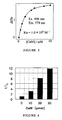
Fig. 3 shows the relationship between the concentration of calmodulin and fluorescence intensity measured in Example 3 of the present invention. -
Fig. 4 shows the relationship between the concentration of calmodulin and fluorescence intensity measured in Example 4 of the present invention. - As described above, the substrate for biochips according to the present invention has a plurality of recesses for immobilizing a biologically relevant substance(s). The number of the recesses per one substrate is not restricted, and it is usually about 100 to 50,000, preferably about 1000 to 10,000 per one substrate having a size of a slide glass. The volume of each recess is not restricted, and is preferably 1 nL to 10 nL. The fact that the desired binding of the target molecules in a test sample occurs at a detectable level in solution systems even if the volume of each recess is so small as mentioned above was not known, and was first discovered by the present invention. Since the volume of each recess is small, the amount of the test sample subjected to the reaction is also small, which is advantageous because the volume of the valuable test sample can be made small. The volume of each well in a microplate, in which binding reactions are carried out in solution systems is 200 µL to 300 µL. Thus, the present inventors first discovered that the desired binding of target molecules in a test sample can be detected in solution systems in a volume of 1/10,000 or less of the well of a microplate. Although the size of each recess is not restricted, when the shape of the recess is cylindrical, one having a diameter of 50 µm to 350 µm, and a depth of about 10 µm to 200 µm, which gives a volume of the above-described about 1 nL to 10 nL is preferred. Although the shape of the recess is not restricted at all, cylindrical one is preferred from the viewpoint of ease of production.
- The inner wall (including the bottom) of the recess is preferably made of carbon such as graphite, diamond, diamond-like carbon or amorphous carbon. To such a carbon, functional groups useful for immobilizing the biological substances can be bound easily at a high density by the methods described below.
- In a preferred mode in which the inner wall of the recess is made of carbon, the substrate is made of a metal, and a carbon layer such as one made of graphite, diamond, diamond-like carbon or amorphous carbon is formed only in the inside of the recess. In this case, as the metal for constituting the substrate, a metal selected from the group consisting of aluminum, titanium, stainless steel and an alloy containing at least one of these metals is preferred because of the reasons that these metals are easy to work, excellent in flatness because they are rigid, excellent in smoothness after polishing because the surface hardness is high, and so on.
- If the surface of the substrate body made of a metal is bent or irregular, diffuse reflection is increased or the focusing in the detection cannot be attained, so that the S/N ratio in the detection is decreased. Therefore, the substrate body is preferably flat and its surface is preferably smooth. Therefore, it is preferred to anneal the substrate body under pressure to eliminate the strain and to promote the flatness after sizing such as punching, and, after grinding the surface to make it smooth, to increase the surface precision by further polishing the surface. These workings for attaining flatness and smoothness can be carried out by conventional metal working methods. In cases where the metal is aluminum or an aluminum alloy, since it is difficult to secure surface precision because the metal is soft, it is preferred to perform a hardening treatment such as electroless NiP plating or anodic oxidation. The surface roughness Ra of the substrate body is preferably less than 1 nm. Although the lower limit of Ra is not restricted, about 0.2 nm is usually close to the limit of working precision. The surface flatness of the substrate body is preferably less than 5 µm. The thickness of the substrate body is not restricted, and is usually about 0.5 mm to 2 mm. In cases where the substrate body is made of aluminum or an aluminum alloy, and a plated layer of NiP or the like is formed on the substrate body, or an oxide layer is formed on the substrate body by anodic oxidation of the surface, the thickness of the plated layer or the oxide layer is not restricted and is usually about 5 µm to 30 µm
- The recesses can be formed in the substrate made of a metal by mechanical processing using a microdrill; laser processing using carbon dioxide laser, YAG laser, excimer laser or the like; energy radiation processing using focused ion beam or the like; lithography processing; press working or the like.
- In cases where a carbon layer is formed in the inside of each recess in the substrate made of a metal, the carbon layer is a layer made of carbon such as graphite, diamond, diamond-like carbon or amorphous carbon, and can be formed by sputtering method, vapor deposition method, CVD (chemical vapor deposition method) or the like. That is, the graphite layer can be formed by, for example, vacuum vapor deposition method using graphite particles as a vapor deposition source. The diamond layer can be formed by, for example, low pressure gas-phase synthesis method using a CVD apparatus having a heat filament. The diamond-like carbon can be formed by, for example, ion-sputtering method or high frequency plasma CVD method. Amorphous carbon can be formed by, for example, high frequency sputtering method. These methods can easily be carried out using commercially available apparatuses. As described above, in cases where the plated layer or oxide layer is formed, the carbon layer is formed thereon. That is, the carbon layer is formed on the surface of the substrate body indirectly through another layer.
- In cases where the carbon layer is formed in the inside of each recess in the substrate made of a metal, it is preferred that the carbon layer be formed only in the inside of each recess and be not formed on the substrate surface between the recesses. As described below, functional groups for immobilizing the biologically relevant substance(s) can be bound to the carbon layer. If the carbon layer is formed only in the inside of each recess and is not formed on the substrate surface between the recesses, the functional groups bound to the carbon layer also exist only in the recesses, so that it is assured that the biologically relevant substance(s) be immobilized only in the recesses. Forming the carbon layer only in the recesses can be attained by, for example, forming the carbon layer on the entire surface of the substrate by the above-described sputtering method, vapor deposition method, CVD method or the like, and then removing the carbon layer formed on the substrate surface between the recesses by grinding the carbon layer. By this method, the carbon layer can be easily formed only in the inside of the small recesses.
- Another preferred method for forming the inner wall of the recesses with carbon is to make the entire substrate with carbon. By forming the substrate itself with carbon such as graphite or amorphous carbon, the inner wall of the recesses can be formed with carbon. In this case, the recesses can be formed by mechanical processing using a microdrill; laser processing using carbon dioxide laser, YAG laser, excimer laser or the like; energy radiation processing using focused ion beam or the like; lithography processing; injection molding; stamping with a number of hard needles, or the like. Even in cases where the entire substrate is made of carbon, the substrate surface is preferably flat, and preferably has a surface roughness within the range described above for the substrates made of a metal. Such a surface roughness can be attained by grinding the surface with a commercially available grinder. The grinding is performed after attaching the functional groups on the entire substrate to remove the functional groups formed on the substrate surface between the recesses.
- The carbon constituting the inner wall of the recesses preferably has functional groups for immobilizing the biologically relevant substance(s). The functional groups can be provided by binding the functional groups to the carbon material constituting the inner wall of the recesses. Examples of the functional groups include, but not limited to, amino group, aldehyde group, carboxyl group, sulfhydryl group and epoxy group. Among these groups, amino group is especially preferred because it is versatile and binding with biologically relevant substances is easy. These functional groups to be covalently bound to the carbon can be covalently bound to the carbon by cleaving C-C bond, C=C bond and/or C-O bond of the carbon by irradiation with plasma or ultraviolet light, and binding the resulting carbon radical with the functional groups or a compound(s) having the functional groups. For example, amino groups can be, as will be described in detail later in the Examples below, covalently bound to carbon by converting the oxygen in the air to ozone and reacting the resulting ozone with the carbon by irradiating the carbon layer with ultraviolet light in the air, then after evacuation, reacting chlorine gas with the resultant to chlorinate the carbon, and, after evacuation, reacting ammonia gas with the resultant to aminate the carbon. Alternatively, amino groups can also be directly introduced by irradiation with ammonia plasma. Still alternatively, amino groups can be generated on the surface by generating radicals by irradiating the substrate surface with argon plasma, converting the radicals to peroxide by air oxidation, and by reacting the resulting peroxide with allylamine or the like. Aldehyde groups can be obtained by, for example, converting the surface of the carbon to an acid chloride, and reducing the resulting acid chloride. Carboxyl groups may be obtained by, for example, converting amino groups to diazonium ions, converting the resulting diazonium ions to nitrile, and hydrolyzing the resulting nitrile. Carboxyl groups can also be obtained by oxidizing alkyl groups with potassium permanganate or the like. Sulfhydryl groups can be obtained by, for example, halogenating the surface of the carbon with light or the like, and reacting the generated halogenated alkyl with a thiol. Epoxy groups may be generated by treating the carbon-carbon double bonds with a peracid. Any of these reactions may be carried out based on the reactions in the field of organic synthetic chemistry, which are well-known by those skilled in the art. The functional groups are not necessarily bound to carbon by covalent bonds, but a compound(s) having the functional group(s) can be noncovalently attached by physical adsorption. For example, amino groups may be given to the carbon layer by physically adsorbing poly-lysine to the carbon layer, which poly-lysine is obtained by polycondensation of lysine which is an amino acid having an amino group in its side chain. The density of the functional groups given to the carbon layer is not restricted, and usually about 10 pmol to 1000 pmol, preferably about 100 pmol to 300 pmol per 1 cm2 of the carbon layer.
- By immobilization of a biologically relevant substance(s) to the recesses of the above-described substrate for biochips, according to the present invention, a biochip can be obtained. Examples of the biologically relevant substances include nucleic acids such as DNAs and RNAs; various proteins, antibodies, enzymes and synthetic and natural peptides; saccharides such as polysaccharides and oligosaccharides; various lipids; and complexes thereof (glycoproteins, glycolipids, lipoproteins and the like). Further, cells can also be immobilized, so that the cell is also included within the scope of the term "biologically relevant substance". Still further, low molecular compounds such as coenzymes, antigen epitopes and haptens are also included within the scope of the term "biologically relevant substance" because they specifically interact with biopolymers such as enzymes and antibodies. These biologically relevant substances may be bound to the above-described carbon layer as they are, or they may be bound to the above-described carbon layer in the state of being immobilized to other carriers such as plastic beads.
- Immobilization of the biologically relevant substance(s) to the carbon material having the functional groups may be carried out by well-known methods through the above-described functional groups. For example, in cases where the functional groups are amino groups, as will be described in detail in the Examples below, biologically relevant substances may be immobilized to the substrate by converting the amino groups to the corresponding anhydride with bromoacetic acid and carbodiimide; reacting the resultant with amino groups to bromoacetylate the surface; and reacting the resultant with sulfhydryl groups in the biologically relevant substances such as peptides. Alternatively, the biologically relevant substances can be immobilized through glutaraldehyde by reacting the amino groups with the amino groups in the biologically relevant molecules. In cases where the functional groups are aldehyde groups, immobilization of the biomolecules desired to be immobilized can be attained by the reaction with the amino groups in the biomolecules. In cases where the functional groups are carboxyl groups, an ester is formed with N-hydroxysuccinimide, and the resulting ester can be bound with the amino groups in the biologically relevant substances. In cases where the functional groups are sulfhydryl groups, immobilization may be attained by selectively bromoacetylating the amino groups in the biologically relevant molecules. Alternatively, immobilization may be attained by binding the sulfhydryl groups with other sulfhydryl groups through disulfides. Further, sulfhydryl groups can be bound by selectively converting the amino groups at the site to be subjected to the immobilization to maleimide, and binding the resultant with the sulfhydryl groups (for example, N-6 maleimide caproic acid is condensed with the amino groups). In cases where the functional groups are epoxy groups, the biologically relevant substances may be immobilized, similarly, by reaction of the epoxy groups with biologically relevant substance having maleimides.
- Not only in cases where, needless to say, the inner wall of the recesses does not have the functional groups, but also in cases where the inner wall of the recesses have the functional groups, it is not necessary to immobilize the biologically relevant substance(s) by covalent bonds (see Example 3 below). By simply placing a solution(s) of the biologically relevant substance(s) to the recesses, and drying the solution(s) to adhere the biologically relevant substance(s) in the recesses, the substrate can be used as a biochip. In this case, a biologically relevant substance(s) which change(s) its(their) fluorescence or the like by binding with a target substance(s) is(are) placed in the recesses. By using such a dry type biochip, a small amount of a test sample can be detected simply. Unlike the measurements in a solution, by performing the measurements after drying the solution to be measured, and by drying the solution of a biologically relevant substance(s) which is a test solution, the chip can be transported and stored. Further, when carrying out the measurement, by drying the substrate after performing the binding reaction between the biologically relevant substance(s) dissolved by adding a test sample solution, and performing the measurement, a simple measurement method with which the evaporation of the small amount of solution is not cared can be realized. Still further, the substrate may be reused.
- The present invention will now be described more concretely by way of examples. However, the present invention is not restricted to the Examples.
- A high purity Al-Mg alloy plate (Mg content: 4% by weight) with a thickness of 1.2 mm was sized to 26 mm x 76 mm by punching with a press. A plurality of the plates were stacked and annealed under pressure under an atmosphere at 340°C, thereby removing strain and attaining a flatness of not more than 5 µm. Thereafter, working of the end faces and chamfer (specifically, angle 45°, a length: 0.2 mm) was performed to prepare plates with a size of 25 mm x 75 mm. Then each plate was ground with a double side grinding machine 16B produced by Speedfam, in which a sponge grindstone was mounted, to attain a thickness of 0.98 mm and a degree of parallelization of not more than 1 µm. Then micro recesses with a size shown in
Fig. 1 were formed in the substrate by mechanical processing with a microdrill using a marking press CAMM-3 produced by Roland. The resulting plate was then subjected to, in the order mentioned, defatting, etching, acid activation, and zincate treatments. More particularly, the plate was sequentially immersed in alkaline degreasing liquid AD-68F (50°C) produced by Uyemura for 5 minutes, in sulfuric acid-phosphoric acid etching liquid AD-101F (80°C) for 2 minutes, in nitric acid activating liquid (20°C) for 1 minute, and in zincate liquid AD-301F3X (20°C) for 30 seconds, thereby carrying out pretreatments. Thereafter, the plate was immersed in electroless NiP liquid NI-422 (90°C) produced by Meltec Corporation for 2 hours to form a plated layer on both sides of the plate, each of which had a thickness of 12 µm. Each of the plated layers was polished by 2 µm with a double side grinding machine 16B produced by Speedfam using colloidal silica abrasive to obtain a plate having ultrasmooth surfaces. The plate had a thickness of 1.00 mm and a surface roughness Ra of 0.35 nm. The flatness, degree of parallelization and Ra were measured using a flat meter FT-50LD produced by Mizojiri, roundness measuring machine Talyrond produced by Rank Taylor Hobson and stylus-type surface roughness meter Talystep produced by Rank Taylor Hobson, respectively. - An amorphous layer was then formed on one surface of the plate using high frequency sputtering apparatus CFS-8EP produced by Tokuda Seisakusho. Particularly, sputtering was carried out for 5 minutes under Ar atmosphere at 1.0 Pa, with a feed traveling wave power (Pf) of 1 kW, and with a reflected wave power (Pr) of 20 W. Thereafter, the surface was polished with a double side grinding machine 16B produced by Speedfam using colloidal silica abrasive to remove the functional groups other than the inner wall of the recesses. Then functional groups were given to the thus formed amorphous carbon layer in the micro recesses. The functional groups were given by the following method: First, the substrate was set in a stainless steel vessel having a window made of a synthetic quartz, and irradiated with an ultraviolet lamp (lamp output power: 110W) from a distance of 3 cm, which lamp emits an ultraviolet light having a component with a wavelength of 185 nm at 30% intensity and a component with a wavelength of 254 nm at 100% intensity, thereby subjecting the surface of the substrate to an ozone treatment. After evacuation, chlorine was then introduced to perform chlorine treatment (25°C, 5 minutes) under chlorine atmosphere at 13 Pa. Further, after evacuation, ammonia was introduced and amination treatment (25°C, 5 minutes) was carried out under ammonia atmosphere at 13 Pa. The amount of the amino groups on the substrate was 4.1 nmol/both surfaces. The amount of the amino groups was measured by a method in which the surfaces of the substrate were treated with hydrochloric acid and then the remaining hydrochloric acid was back titrated with aqueous sodium hydroxide solution (Japanese Patent Application No.
2005-069554 - After placing a thermosetting phenol resin in a mold, a two-step heat treatment at 90°C and 120°C was performed to prepare a bakelite block. A plate having a thickness of 2 mm and a size of 31 mm x 95 mm was cut out from the block, and was ground with a double side grinding machine 16B produced by Speedfam, in which an iron surface plate was mounted, to attain a thickness of 1.30 mm and a degree of parallelization of not more than 1 µm. After chamfering, the resulting plate was slowly heated to 1200°C thereby carbonizing the substrate to glassy carbon. Thereafter, using a LD-excited YVO4 laser produced by Fuji Electric, the small recesses having the size shown in
Fig. 1 were formed in the air, and then functional groups were attached by the following method: First, the substrate was set in a stainless steel vessel having a window made of a synthetic quartz, and irradiated with an ultraviolet lamp (lamp output power: 110W) from a distance of 3 cm, which lamp emits an ultraviolet light having a component with a wavelength of 185 nm at 30% intensity and a component with a wavelength of 254 nm at 100% intensity, thereby subjecting the surface of the substrate to an ozone treatment. After evacuation, chlorine was then introduced to perform chlorine treatment (25°C, 5 minutes) under chlorine atmosphere at 13 Pa. Further, after evacuation, ammonia was introduced and amination treatment (25°C, 5 minutes) was carried out under ammonia atmosphere at 13 Pa. The amount of the amino groups on the substrate was 4.1 nmol/both surfaces. The amount of the amino groups was measured by a method in which the surfaces of the substrate were treated with hydrochloric acid and then the remaining hydrochloric acid was back titrated with aqueous sodium hydroxide solution (Japanese Patent Application No.2005-069554 - Calmodulin was measured using a peptide chip having recesses in which a peptide having α-helix structure was immobilized, which peptide was labeled with different fluorecence labels at its both ends. More specifically, this was carried out as follows:
- The sequence of the core region of the peptide having α-helix structure was designed by molecular modeling using a computer (molecular modeling using Insight II/Discover of Molecular Simulation, U.S.) based on the amino acid sequence of the peptide described in a reference (K. T. O'Neil and W.F.DeGrado, Trend Biochem Sci, 15, 59-64 (1990)). As a result, the designed amino acid sequence of the core region was Leu-Lys-Lys-Leu-Leu-Lys-Leu-Leu-Lys-Lys-Leu-Leu-Lys-Leu (SEQ ID NO:1). This sequence is known to specifically bind to calmodulin. To this sequence, a Cys residue as an anchor for immobilization, and as fluorescently labeled residues, Lys(TAMRA) and Lys(FAM) were added. Thus, an amino acid sequence Cys-Lys(TAMRA)-Leu-Lys-Lys-Leu-Leu-Lys-Leu-Leu-Lys-Lys-Leu-Leu-Lys-Leu-Lys(FAM)-NH2 (SEQ ID NO:2) was synthesized. Fluorescent amino acid derivatives were prepared by introducing a fluorescent group to the side chain of lysine, and were used as building blocks for the synthesis. That is, the fluorescently modified amino acid derivatives were converted to N-hydroxysuccinimide active ester derivatives using diisopropylcarbidiimide. The amino group in the side chain of Fmoc-Lys-OH (Novabiochem,Switzerland, Product No.04-12-1042) and the above-described active ester were reacted by a conventional method in dimethylformamide overnight at room temperature with stirring, and then the reaction mixture was concentrated and subjected to precipitation with ether to obtain Fmoc-Lys(TAMRA)-OH. Yield: 80%. (Fmoc: fluorenyl-methylcarbonyl). In the similar manner, Fmoc-Lys(FAM)-OH was obtained. Yield: 85%
- By using these fluorecent derivatives as building blocks, the synthetic peptide shown in
Fig. 2 having the labels A and B was synthesized by the conventional solid phase peptide synthesis by Fmoc method in a scale of 15 micromoles each. That is, Fmoc-amino acid derivatives were sequentially polycondensed using TentaGel SRAM, Rapp Polymere, Germany, Product No.: S30-023 (Rink amide resin with polyethylene glycol chain) as the solid support. More specifically, the synthesis was carried out by the method described in Japanese Patent No.2007165 - The synthesized labeled peptide was dissolved in 60% DMF to a concentration of 1.0 µM, and the obtained solution was placed in each recess in the substrate prepared in Example 1 or Example 2 using SpotBot (TeleChem International, U.S.) in an amount of 1.8 nL per recess, thereby placing the fluorescently labeled α-peptide (the substance to be recognized) in the recesses. In this case, the peptide was not immobilized. After adding the peptide solution to each recess and drying the solution, quantification of the binding (recognition) was tried. Calmodulin was dissolved in a solution containing 20 mM Tris-HCL, 100 µM CaCl2, 150 mM NaCl and 20 mM PEG2000, and the resulting solution was placed in each recess in an amount of 3.9 nL (0.5 mg/mL) per recess. The substrate was incubated at 25°C and immediately the measurement with a fluorecent scanner (CRBIO IIe produced by Hitachi Soft Engineering) was carried out (excitation wavelength: 498 nm, measurement wavelength: 579 nm).
- The results of the measurement on the substrate prepared in Example 1 are shown in
Fig. 3 . The fluorescence changed depending on the calmodulin concentration, so that it was proved that quantification of calmodulin can be attained using this biochip. Similar results were obtained also when the substrate of Example 2 was used. - As the peptide to be immobilized to the functional groups on the carbon layer in the recesses of the biochip prepared in Example 1, a fluorescently labeled peptide having the following sequence was chemically synthesized: Ac-Cys-Gly-Lys(FAM)-Gly-Leu-Lys-Lys-Leu-Leu-Lys-Leu-Leu-Lys-Lys-Leu-Leu-Lys-Leu-Lys(TAMRA)-Gly-NH2 (SEQ ID NO:3).
The fact that this peptide has α-helix structure was confirmed by CD spectrum.
Here, both "FAM" and "TAMRA" are fluorescent dyes. When FAM is excited with light, the excitation energy of FAM is transferred to TAMRA depending on the distance between FAM and TAMRA, and TAMRA emits fluorescence (called fluorescence resonance energy transfer, FRET-fluorescence). When a protein binds to the peptide, the helix structure of the peptide is fixed, so that FRET florescence is increased. FRET is a phenomenon that energy is transferred from a donor molecule (FAM in this case) in the excited state to an acceptor molecule (TAMRA in this case) in the ground state, and fluorescence from the acceptor is observed. The peptide is known to specifically bind to calmodulin (CaM). Upon binding to CaM, the distance between FAM and TAMRA is decreased. The larger the amount of CaM, the higher the measured fluorescence intensity from TAMRA, so that the binding can be quantified. - The above-described labeled peptide was dissolved in 60% dimethylformamide (DMF) to a concentration of 2 µM. On the other hand, the amino groups on the substrate prepared in Example 1 were bromoacetylated. Specifically, this was carried out as follows: Bromoacetic acid (BrAcOH, Tokyo Chemical Industry, Mw=138.95, 2.00 mmol, 278 mg) and dicyclohexylcarbodiimide (DCC) (Aldrich Mw=206.33, 1.00 mmol, 206 mg) were dissolved in tetrahydrofuran (3.33 ml), and the resulting solution was gently shaken at room temperature for 60 minutes to form bromoacetic anhydride. The generated insoluble urea was removed by filtration. The resulting aminated substrate was immersed in 5% solution of diisopropylethylamine in NMP and lightly rinsed. The filtrate obtained above was added to this substrate and the substrate was immersed therein at room temperature for 1 hour while lightly shaking the substrate sometimes, thereby attaining bromination. The resulted substrate was washed with ultrapure water (Milli-Q water (trademark)), and dried under nitrogen. The above-described labeled peptide solution was spotted on the substrate to react the peptide with the above-described bromoacetylated amino groups, thereby to immobilize the peptide on the substrate. The spotting was carried out using SpotBot apparatus produced by TeleChem International (California, U.S.) and using a microspotting pin also produced by TeleChem International.
- To the thus prepared labeled peptide-immobilized substrate, solutions containing different amounts of CaM (CaM was dissolved in 100 µM calcium chloride solution) were applied, and fluorescence was measured using a scanner (CRBIO IIe produced by Hitachi Software Engineering).
- The results are shown in
Fig. 4 . As shown inFig. 4 , the measured fluorescence intensity increased dependently on the amount of CaM. Thus, it was proved that a substance which specifically reacts with the biologically relevant substance immobilized on the chip can be quantified by the biochip according to the present invention. Example 5 - Three milligrams of (N-(6-maleimidocaproyloxy)succinimide)) produced by Dojin (hereinafter referred to as "EMCS") was weighed, and dissolved in a 2:4:4 mixed solution of dimethylsulfoxide (DMSO)/dimethylformamide (DMF)/dioxane to a final concentration of 0.3 mg/mL, thereby preparing an EMCS solution. The aminated substrate was immersed in this solution at room temperature for 30 minutes, thereby allowing reaction between the amino groups and EMCS active ester. The substrate was then washed with ethanol to remove the unreacted EMCS and reaction side products. Then the substrate was dried under a nitrogen atmosphere to prepare a modified substrate in which only the inside of the microwells was maleimidated.
- A peptide having α-helix structure labeled with a fluorescent group TAMRA alone Ac-Cys-Gly-Leu-Lys-Lys-Leu-Leu-Lys-Leu-Leu-Lys-Lys-Leu-Leu-Lys-Leu-Lys(TAMRA)-Gly-NH2 (SEQ ID NO:4) was synthesized by a conventional method. When a protein binds to this peptide, the helix structure is changed, and fluorescence intensity is changed accordingly. This peptide is known to specifically binds to calmodulin (CaM) which is a protein, and the larger the amount of CaM, the higher the fluorescence intensity of TAMRA measured, so that CaM can be quantified.
- The peptide was dissolved in DMF/pH8.0, 10 mM Tris-HCl (1:1) to a final concentration of 2.0 µM. This peptide solution in an amount of 3.9 nL was added to the substrate using SpotBot produced by TeleChem International (California, U.S.) and using a microspotting pin also produced by TeleChem International. By leaving the substrate to stand for 30 minutes, the maleimide groups and the thiol groups in the cystein of the peptide reacted and the peptide was immobilized. The substrate was washed with DMF/water (1:1).
- Solutions containing different amounts of CaM (CaM was dissolved in 100 µM calcium chloride solution) was added to each micro recess in an amount of 3.9 nL per recess using SpotBot produced by TeleChem International (California, U.S). After washing the substrate with Milli-Q water (trade name), fluorescence intensity was measured using a scanner (CRBIO IIe produced by Hitachi Soft Engineering).
- The results shown in
Fig. 3 were obtained. Thus, the measured fluorescence intensity changed depending on the amount of CaM added to the substrate, so that it was proved that substances which specifically react with the biologically relevant substance immobilized on the chip can be quantified by the biochip of the present invention.

Claims (14)
- A substrate for biochips, which substrate has a plurality of recesses formed therein for immobilizing a biologically relevant substance(s).
- The substrate according to claim 1, wherein each of said recesses has a volume of 1 nL to 10 nL.
- The substrate according to claim 1 or 2, wherein inner side of each of said recesses is made of carbon.
- The substrate according to claim 3, wherein said substrate is made of a metal and a carbon layer is formed only in the inside of each of said recesses.
- The substrate according to claim 4, wherein said metal is selected from the group consisting of aluminum, titanium, stainless steel and alloys containing at least one of the metals mentioned.
- The substrate according to claim 5, wherein said metal is aluminum or an alloy thereof, and a plated layer or a layer of oxide of said metal is formed between said substrate and said carbon layer.
- The substrate according to any one of claims 4 to 6, wherein said carbon layer is made of graphite, diamond, diamond-like carbon or amorphous carbon.
- The substrate according to claim 3, wherein said substrate is made of carbon.
- The substrate according to claim 8, wherein said substrate is made of graphite or amorphous carbon.
- The substrate according to any one of claims 3 to 9, wherein said carbon constituting the inner walls of said recesses have functional groups.
- The substrate according to claim 10, wherein said functional groups are amino groups, aldehyde groups, carboxyl groups, sulfhydryl groups or epoxy groups, or polylysine non-covalently bound to said carbon layer.
- A biochip comprising said substrate according to any one of claims 1 to 11, and a biologically relevant substance immobilized on said substrate.
- A method of producing a biochip, said method comprising the steps of providing said substrate for biochips, according to any one of claims 1 to 11; and immobilizing a biologically relevant substance(s) on said substrate.
- Use of said substrate for biochips, according to any one of claims 1 to 11, for the production of a substrate for biochips.
Applications Claiming Priority (2)
| Application Number | Priority Date | Filing Date | Title |
|---|---|---|---|
| JP2005177466A JP5041680B2 (en) | 2005-06-17 | 2005-06-17 | Biochip substrate and biochip |
| PCT/JP2006/312119 WO2006135045A1 (en) | 2005-06-17 | 2006-06-16 | Biochip substrate and biochip |
Publications (4)
| Publication Number | Publication Date |
|---|---|
| EP2006679A2 true EP2006679A2 (en) | 2008-12-24 |
| EP2006679A9 EP2006679A9 (en) | 2009-07-01 |
| EP2006679A4 EP2006679A4 (en) | 2009-08-05 |
| EP2006679B1 EP2006679B1 (en) | 2014-03-05 |
Family
ID=37532398
Family Applications (1)
| Application Number | Title | Priority Date | Filing Date |
|---|---|---|---|
| EP06766807.9A Ceased EP2006679B1 (en) | 2005-06-17 | 2006-06-16 | Biochip substrate and biochip |
Country Status (4)
| Country | Link |
|---|---|
| US (1) | US9778256B2 (en) |
| EP (1) | EP2006679B1 (en) |
| JP (1) | JP5041680B2 (en) |
| WO (1) | WO2006135045A1 (en) |
Families Citing this family (7)
| Publication number | Priority date | Publication date | Assignee | Title |
|---|---|---|---|---|
| KR100780405B1 (en) * | 2005-08-31 | 2007-11-28 | 재단법인서울대학교산학협력재단 | NR-specific binding peptide search method using alpha helical peptide |
| JP2008232899A (en) * | 2007-03-22 | 2008-10-02 | Sumitomo Bakelite Co Ltd | Substrate and its usage |
| JP5062524B2 (en) * | 2007-08-29 | 2012-10-31 | 株式会社ハイペップ研究所 | Quantitative determination of functional groups on solid substrate surface |
| JP2009128093A (en) * | 2007-11-21 | 2009-06-11 | Sumitomo Bakelite Co Ltd | Method of detecting physiological active substance |
| KR101035957B1 (en) | 2009-11-26 | 2011-05-23 | 한국생명공학연구원 | Manufacturing method of single-step biochip with reduced bleeding |
| US11014088B2 (en) * | 2016-03-09 | 2021-05-25 | The Board Of Regents Of The University Of Texas System | Sensitive ELISA for disease diagnosis on surface modified poly(methyl methacrylate) (PMMA) microfluidic microplates |
| CN111483971B (en) * | 2020-01-17 | 2023-05-23 | 杭州电子科技大学 | A biaxially symmetric porous cavity array structure and its preparation method |
Family Cites Families (12)
| Publication number | Priority date | Publication date | Assignee | Title |
|---|---|---|---|---|
| JPH027165A (en) | 1988-06-27 | 1990-01-11 | Toshiba Corp | Electronic equipment |
| AU5173598A (en) * | 1996-11-08 | 1998-06-10 | Ikonos Corporation | Method for coating substrates |
| US20020090649A1 (en) * | 1999-12-15 | 2002-07-11 | Tony Chan | High density column and row addressable electrode arrays |
| AU2108901A (en) * | 1999-12-15 | 2001-06-25 | Motorola, Inc. | Column and row addressable high density biochip array |
| KR100455284B1 (en) * | 2001-08-14 | 2004-11-12 | 삼성전자주식회사 | High-throughput sensor for detecting biomolecules using carbon nanotubes |
| JP4207528B2 (en) * | 2001-10-24 | 2009-01-14 | 東レ株式会社 | Method for binding selective binding substances |
| JP3860130B2 (en) * | 2002-08-21 | 2006-12-20 | 東洋鋼鈑株式会社 | Method for mass spectrometry by desorption / ionization of a solid support and a plurality of substances or complexes immobilized on the solid support |
| JP2004226384A (en) * | 2003-01-27 | 2004-08-12 | Foundation For Advancement Of Science & Technology | Nucleic acid detection chip and method of using the same |
| KR100549103B1 (en) * | 2003-06-05 | 2006-02-06 | 한국과학기술원 | Manufacturing method of carbon nanotube array |
| JP2005017073A (en) * | 2003-06-25 | 2005-01-20 | Bml Inc | Detection method using detection instrument |
| JP4280124B2 (en) * | 2003-07-25 | 2009-06-17 | 東洋鋼鈑株式会社 | Vacuum packed solid support array and manufacturing method thereof |
| JP4007269B2 (en) * | 2003-07-29 | 2007-11-14 | オムロン株式会社 | Biomolecule shape transfer method, chip substrate manufacturing method, and biochip manufacturing method |
-
2005
- 2005-06-17 JP JP2005177466A patent/JP5041680B2/en not_active Expired - Fee Related
-
2006
- 2006-06-16 US US11/922,108 patent/US9778256B2/en not_active Expired - Fee Related
- 2006-06-16 WO PCT/JP2006/312119 patent/WO2006135045A1/en not_active Ceased
- 2006-06-16 EP EP06766807.9A patent/EP2006679B1/en not_active Ceased
Also Published As
| Publication number | Publication date |
|---|---|
| US20100130380A1 (en) | 2010-05-27 |
| EP2006679B1 (en) | 2014-03-05 |
| US9778256B2 (en) | 2017-10-03 |
| EP2006679A9 (en) | 2009-07-01 |
| EP2006679A4 (en) | 2009-08-05 |
| WO2006135045A1 (en) | 2006-12-21 |
| JP5041680B2 (en) | 2012-10-03 |
| JP2006349552A (en) | 2006-12-28 |
Similar Documents
| Publication | Publication Date | Title |
|---|---|---|
| US8137942B2 (en) | Method of preparing a modified surface | |
| Wu et al. | DNA and protein microarray printing on silicon nitride waveguide surfaces | |
| CN1934451B (en) | Method of agitating solution | |
| AU2006299641B2 (en) | Reactive surfaces, substrates and methods for producing and using same | |
| US8158340B2 (en) | Methods for detecting conformational changes in bioentities | |
| EP2306197A1 (en) | Biochip substratum and method for production thereof | |
| JP2002214142A (en) | Fluorescence analysis element using metal nanowell and method of manufacturing the same | |
| US9778256B2 (en) | Biochip substrate and biochip | |
| US8455400B2 (en) | Substrate for biochip and biochip | |
| EP1644527B9 (en) | Cucurbituril derivative-bonded solid substrate and biochip using the same | |
| EP1567569B1 (en) | Method for immobilizing biologic molecules on solid surfaces | |
| US20070004027A1 (en) | Method for manufacturing a biosensor element | |
| JP4207528B2 (en) | Method for binding selective binding substances | |
| EP1587839B1 (en) | Light induced immobilisation | |
| JP3448654B2 (en) | Biochip, biochip array, and screening method using them | |
| CN119869636A (en) | Universal biochip, and preparation method and application thereof | |
| JP4526388B2 (en) | Biochip manufacturing method | |
| US20080274917A1 (en) | Surface activation methods for polymeric substrates to provide biochip platforms and methods for detection of biomolecules thereon | |
| JP4797619B2 (en) | Analysis chip and analysis method of test substance | |
| KR101035957B1 (en) | Manufacturing method of single-step biochip with reduced bleeding | |
| JP4300183B2 (en) | Polyamide solid phase with functional groups | |
| Chin et al. | Antibody-modified microwell arrays and photobiotin patterning on hydrocarbon-free glass | |
| WO2008056837A1 (en) | Method for fabricating a biomaterial array using photoreaction | |
| Tan et al. | In situSynthesis of Oligonucleotide and Detection of Gold‐label‐silver‐stain on PTFE Slices |
Legal Events
| Date | Code | Title | Description |
|---|---|---|---|
| PUAI | Public reference made under article 153(3) epc to a published international application that has entered the european phase |
Free format text: ORIGINAL CODE: 0009012 |
|
| PUAB | Information related to the publication of an a document modified or deleted |
Free format text: ORIGINAL CODE: 0009199EPPU |
|
| 17P | Request for examination filed |
Effective date: 20080114 |
|
| AK | Designated contracting states |
Kind code of ref document: A2 Designated state(s): DE FR GB |
|
| A4 | Supplementary search report drawn up and despatched |
Effective date: 20090703 |
|
| RIC1 | Information provided on ipc code assigned before grant |
Ipc: B01L 3/00 20060101ALI20090629BHEP Ipc: G01N 37/00 20060101ALI20090629BHEP Ipc: G01N 33/547 20060101ALI20090629BHEP Ipc: G01N 33/543 20060101ALI20090629BHEP Ipc: C12N 15/09 20060101ALI20090629BHEP Ipc: G01N 33/53 20060101AFI20070209BHEP Ipc: C12M 1/00 20060101ALI20090629BHEP |
|
| 17Q | First examination report despatched |
Effective date: 20091014 |
|
| REG | Reference to a national code |
Ref country code: DE Ref legal event code: R079 Ref document number: 602006040506 Country of ref document: DE Free format text: PREVIOUS MAIN CLASS: G01N0033530000 Ipc: B82Y0030000000 |
|
| RIC1 | Information provided on ipc code assigned before grant |
Ipc: B82Y 30/00 20110101AFI20130911BHEP Ipc: G01N 33/53 20060101ALI20130911BHEP Ipc: G01N 33/547 20060101ALI20130911BHEP Ipc: B01L 3/00 20060101ALI20130911BHEP Ipc: C12M 1/00 20060101ALI20130911BHEP Ipc: C12N 15/09 20060101ALI20130911BHEP Ipc: G01N 33/543 20060101ALI20130911BHEP |
|
| GRAP | Despatch of communication of intention to grant a patent |
Free format text: ORIGINAL CODE: EPIDOSNIGR1 |
|
| RBV | Designated contracting states (corrected) |
Designated state(s): DE FR GB |
|
| RAP1 | Party data changed (applicant data changed or rights of an application transferred) |
Owner name: NIPPON LIGHT METAL COMPANY, LTD. Owner name: HIPEP LABORATORIES |
|
| INTG | Intention to grant announced |
Effective date: 20131031 |
|
| GRAS | Grant fee paid |
Free format text: ORIGINAL CODE: EPIDOSNIGR3 |
|
| GRAA | (expected) grant |
Free format text: ORIGINAL CODE: 0009210 |
|
| AK | Designated contracting states |
Kind code of ref document: B1 Designated state(s): DE FR GB |
|
| REG | Reference to a national code |
Ref country code: GB Ref legal event code: FG4D |
|
| REG | Reference to a national code |
Ref country code: DE Ref legal event code: R096 Ref document number: 602006040506 Country of ref document: DE Effective date: 20140417 |
|
| REG | Reference to a national code |
Ref country code: DE Ref legal event code: R097 Ref document number: 602006040506 Country of ref document: DE |
|
| PLBE | No opposition filed within time limit |
Free format text: ORIGINAL CODE: 0009261 |
|
| STAA | Information on the status of an ep patent application or granted ep patent |
Free format text: STATUS: NO OPPOSITION FILED WITHIN TIME LIMIT |
|
| 26N | No opposition filed |
Effective date: 20141208 |
|
| REG | Reference to a national code |
Ref country code: DE Ref legal event code: R097 Ref document number: 602006040506 Country of ref document: DE Effective date: 20141208 |
|
| REG | Reference to a national code |
Ref country code: FR Ref legal event code: PLFP Year of fee payment: 11 |
|
| REG | Reference to a national code |
Ref country code: FR Ref legal event code: PLFP Year of fee payment: 12 |
|
| REG | Reference to a national code |
Ref country code: FR Ref legal event code: PLFP Year of fee payment: 13 |
|
| P01 | Opt-out of the competence of the unified patent court (upc) registered |
Effective date: 20230522 |
|
| PGFP | Annual fee paid to national office [announced via postgrant information from national office to epo] |
Ref country code: FR Payment date: 20230525 Year of fee payment: 18 Ref country code: DE Payment date: 20230525 Year of fee payment: 18 |
|
| PGFP | Annual fee paid to national office [announced via postgrant information from national office to epo] |
Ref country code: GB Payment date: 20230517 Year of fee payment: 18 |
|
| REG | Reference to a national code |
Ref country code: DE Ref legal event code: R119 Ref document number: 602006040506 Country of ref document: DE |
|
| GBPC | Gb: european patent ceased through non-payment of renewal fee |
Effective date: 20240616 |
|
| PG25 | Lapsed in a contracting state [announced via postgrant information from national office to epo] |
Ref country code: DE Free format text: LAPSE BECAUSE OF NON-PAYMENT OF DUE FEES Effective date: 20250101 |
|
| PG25 | Lapsed in a contracting state [announced via postgrant information from national office to epo] |
Ref country code: FR Free format text: LAPSE BECAUSE OF NON-PAYMENT OF DUE FEES Effective date: 20240630 |
|
| PG25 | Lapsed in a contracting state [announced via postgrant information from national office to epo] |
Ref country code: GB Free format text: LAPSE BECAUSE OF NON-PAYMENT OF DUE FEES Effective date: 20240616 |