EP2006600B1 - Poly valve device for gas tank - Google Patents
Poly valve device for gas tank Download PDFInfo
- Publication number
- EP2006600B1 EP2006600B1 EP07110903A EP07110903A EP2006600B1 EP 2006600 B1 EP2006600 B1 EP 2006600B1 EP 07110903 A EP07110903 A EP 07110903A EP 07110903 A EP07110903 A EP 07110903A EP 2006600 B1 EP2006600 B1 EP 2006600B1
- Authority
- EP
- European Patent Office
- Prior art keywords
- valve
- valve body
- overfill protection
- level
- poly
- Prior art date
- Legal status (The legal status is an assumption and is not a legal conclusion. Google has not performed a legal analysis and makes no representation as to the accuracy of the status listed.)
- Not-in-force
Links
Images


Classifications
-
- F—MECHANICAL ENGINEERING; LIGHTING; HEATING; WEAPONS; BLASTING
- F17—STORING OR DISTRIBUTING GASES OR LIQUIDS
- F17C—VESSELS FOR CONTAINING OR STORING COMPRESSED, LIQUEFIED OR SOLIDIFIED GASES; FIXED-CAPACITY GAS-HOLDERS; FILLING VESSELS WITH, OR DISCHARGING FROM VESSELS, COMPRESSED, LIQUEFIED, OR SOLIDIFIED GASES
- F17C13/00—Details of vessels or of the filling or discharging of vessels
- F17C13/04—Arrangement or mounting of valves
-
- F—MECHANICAL ENGINEERING; LIGHTING; HEATING; WEAPONS; BLASTING
- F17—STORING OR DISTRIBUTING GASES OR LIQUIDS
- F17C—VESSELS FOR CONTAINING OR STORING COMPRESSED, LIQUEFIED OR SOLIDIFIED GASES; FIXED-CAPACITY GAS-HOLDERS; FILLING VESSELS WITH, OR DISCHARGING FROM VESSELS, COMPRESSED, LIQUEFIED, OR SOLIDIFIED GASES
- F17C13/00—Details of vessels or of the filling or discharging of vessels
- F17C13/02—Special adaptations of indicating, measuring, or monitoring equipment
- F17C13/021—Special adaptations of indicating, measuring, or monitoring equipment having the height as the parameter
-
- F—MECHANICAL ENGINEERING; LIGHTING; HEATING; WEAPONS; BLASTING
- F17—STORING OR DISTRIBUTING GASES OR LIQUIDS
- F17C—VESSELS FOR CONTAINING OR STORING COMPRESSED, LIQUEFIED OR SOLIDIFIED GASES; FIXED-CAPACITY GAS-HOLDERS; FILLING VESSELS WITH, OR DISCHARGING FROM VESSELS, COMPRESSED, LIQUEFIED, OR SOLIDIFIED GASES
- F17C2221/00—Handled fluid, in particular type of fluid
- F17C2221/03—Mixtures
- F17C2221/032—Hydrocarbons
- F17C2221/035—Propane butane, e.g. LPG, GPL
-
- F—MECHANICAL ENGINEERING; LIGHTING; HEATING; WEAPONS; BLASTING
- F17—STORING OR DISTRIBUTING GASES OR LIQUIDS
- F17C—VESSELS FOR CONTAINING OR STORING COMPRESSED, LIQUEFIED OR SOLIDIFIED GASES; FIXED-CAPACITY GAS-HOLDERS; FILLING VESSELS WITH, OR DISCHARGING FROM VESSELS, COMPRESSED, LIQUEFIED, OR SOLIDIFIED GASES
- F17C2223/00—Handled fluid before transfer, i.e. state of fluid when stored in the vessel or before transfer from the vessel
- F17C2223/01—Handled fluid before transfer, i.e. state of fluid when stored in the vessel or before transfer from the vessel characterised by the phase
- F17C2223/0146—Two-phase
- F17C2223/0153—Liquefied gas, e.g. LPG, GPL
-
- F—MECHANICAL ENGINEERING; LIGHTING; HEATING; WEAPONS; BLASTING
- F17—STORING OR DISTRIBUTING GASES OR LIQUIDS
- F17C—VESSELS FOR CONTAINING OR STORING COMPRESSED, LIQUEFIED OR SOLIDIFIED GASES; FIXED-CAPACITY GAS-HOLDERS; FILLING VESSELS WITH, OR DISCHARGING FROM VESSELS, COMPRESSED, LIQUEFIED, OR SOLIDIFIED GASES
- F17C2223/00—Handled fluid before transfer, i.e. state of fluid when stored in the vessel or before transfer from the vessel
- F17C2223/03—Handled fluid before transfer, i.e. state of fluid when stored in the vessel or before transfer from the vessel characterised by the pressure level
- F17C2223/033—Small pressure, e.g. for liquefied gas
-
- F—MECHANICAL ENGINEERING; LIGHTING; HEATING; WEAPONS; BLASTING
- F17—STORING OR DISTRIBUTING GASES OR LIQUIDS
- F17C—VESSELS FOR CONTAINING OR STORING COMPRESSED, LIQUEFIED OR SOLIDIFIED GASES; FIXED-CAPACITY GAS-HOLDERS; FILLING VESSELS WITH, OR DISCHARGING FROM VESSELS, COMPRESSED, LIQUEFIED, OR SOLIDIFIED GASES
- F17C2250/00—Accessories; Control means; Indicating, measuring or monitoring of parameters
- F17C2250/04—Indicating or measuring of parameters as input values
- F17C2250/0404—Parameters indicated or measured
- F17C2250/0408—Level of content in the vessel
-
- F—MECHANICAL ENGINEERING; LIGHTING; HEATING; WEAPONS; BLASTING
- F17—STORING OR DISTRIBUTING GASES OR LIQUIDS
- F17C—VESSELS FOR CONTAINING OR STORING COMPRESSED, LIQUEFIED OR SOLIDIFIED GASES; FIXED-CAPACITY GAS-HOLDERS; FILLING VESSELS WITH, OR DISCHARGING FROM VESSELS, COMPRESSED, LIQUEFIED, OR SOLIDIFIED GASES
- F17C2250/00—Accessories; Control means; Indicating, measuring or monitoring of parameters
- F17C2250/04—Indicating or measuring of parameters as input values
- F17C2250/0404—Parameters indicated or measured
- F17C2250/0408—Level of content in the vessel
- F17C2250/0413—Level of content in the vessel with floats
-
- F—MECHANICAL ENGINEERING; LIGHTING; HEATING; WEAPONS; BLASTING
- F17—STORING OR DISTRIBUTING GASES OR LIQUIDS
- F17C—VESSELS FOR CONTAINING OR STORING COMPRESSED, LIQUEFIED OR SOLIDIFIED GASES; FIXED-CAPACITY GAS-HOLDERS; FILLING VESSELS WITH, OR DISCHARGING FROM VESSELS, COMPRESSED, LIQUEFIED, OR SOLIDIFIED GASES
- F17C2250/00—Accessories; Control means; Indicating, measuring or monitoring of parameters
- F17C2250/07—Actions triggered by measured parameters
- F17C2250/072—Action when predefined value is reached
- F17C2250/075—Action when predefined value is reached when full
-
- F—MECHANICAL ENGINEERING; LIGHTING; HEATING; WEAPONS; BLASTING
- F17—STORING OR DISTRIBUTING GASES OR LIQUIDS
- F17C—VESSELS FOR CONTAINING OR STORING COMPRESSED, LIQUEFIED OR SOLIDIFIED GASES; FIXED-CAPACITY GAS-HOLDERS; FILLING VESSELS WITH, OR DISCHARGING FROM VESSELS, COMPRESSED, LIQUEFIED, OR SOLIDIFIED GASES
- F17C2260/00—Purposes of gas storage and gas handling
- F17C2260/02—Improving properties related to fluid or fluid transfer
- F17C2260/022—Avoiding overfilling
-
- F—MECHANICAL ENGINEERING; LIGHTING; HEATING; WEAPONS; BLASTING
- F17—STORING OR DISTRIBUTING GASES OR LIQUIDS
- F17C—VESSELS FOR CONTAINING OR STORING COMPRESSED, LIQUEFIED OR SOLIDIFIED GASES; FIXED-CAPACITY GAS-HOLDERS; FILLING VESSELS WITH, OR DISCHARGING FROM VESSELS, COMPRESSED, LIQUEFIED, OR SOLIDIFIED GASES
- F17C2270/00—Applications
- F17C2270/01—Applications for fluid transport or storage
- F17C2270/0165—Applications for fluid transport or storage on the road
- F17C2270/0168—Applications for fluid transport or storage on the road by vehicles
Definitions
- the present invention is directed to a poly valve for a gas tank, more particularly for a gas tank of a vehicle, preferably a LPG tank.
- Patent document EP 1 688 650 A1 disposes a poly valve device according to the preamble of claim 1.
- a poly valve device for a LPG tank is already known from FR 2 816 033 A (GIAT INDUSTRIES) 03.05.2002.
- the device disclosed therein comprises a valve body with a flange for mounting on a gas tank, an overfill sensing means, an electrically operated overfull protection valve connected to the overfill sensing means, a valve means for delivering gas to the end user and a liquid level gauge transmitting its information electrically via a wire connection through the poly valve body.
- the present invention seeks to solve the above mentioned problem by proposing a poly valve device for a gas tank, according to claim 1.
- the overfill protection valve is mounted on the valve body by fitting and crimping.
- the overfill protection valve can comprise a generally cylindrical overfill protection valve body, one end of which being fitted and crimped in a corresponding bore of the valve body.
- the level indicator means comprises an elongated element rotatably supported on the valve body and generally perpendicular to the flange, a first end of the elongated element cooperating with the hinged section of the level sensing means and the second end of the elongated element transmitting by its rotation the information of the level of liquid in the tank to the external side of the valve body.
- the second end of the elongated element can comprise magnetic means designed for transmitting the rotational position of the elongated element to an indicator on the external side of the valve body.
- the first end of the elongated element can comprise a slot distant from a rotational axis of the elongated element and engaging with the rod or a pivot of the hinged section.
- the overfill protection valve can comprise a piston with sealing means for closing the overfill protection valve, the piston having a polygonal, preferably hexagonal, section.
- the piston has a passage from an upper side with the sealing means to a lower side of the piston and the overfill protection valve further comprises an overfill protection valve body and a control valve operated by the level sensing means and able to close a chamber of the overfill protection valve formed by the lower side of the piston and the overfill protection valve body.
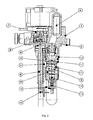
- Figure 1 is a view of the poly valve device of the present invention.
- Figure 2 is a sectional view of the poly valve device of figure 1 .
- Figure 3 is a perspective view of the device of the present invention.
- the poly valve device comprises a valve body 1 with a flange 2 for sealingly mounting on a flat portion of a gas tank, for example, a gas powered vehicle.
- the device comprises a series of devices for fulfilling a series of functions:
- shut-off valve for gas delivery to the end user.
- This valve is located approximately in the middle of the valve body 1 (it cannot be seen on the figures) and mounted from the upper side of the valve body.
- the valve is actuated by a magnetic coil screwed on top of the shut-off valve. This magnetic coil is apparent on the top of the valve illustrated on the figures.
- overfill protection valve 3 mounted on the lower side of the valve body within the contour of the flange.
- the details of this protection valve are illustrated on figure 2 which shows a hollow overfill protection valve body 11 fitted in a bore 12 of the valve body.
- the overfill protection valve is thereby in fluid connection with a passageway made in the valve body 1 extending from the lower side to the lower side of this latter.
- the passageway is in connection with a fill port 4 on the upper side of the valve body 1.
- a check valve is located in the passageway in order to allow a flow of gas from the fill port to the gas tank and to block any counter flow from the tank to the fill port.
- the overfill protection valve body 11 is generally cylindrical and comprises a piston 17 slidably mounted therein.
- This piston has sealing means at its upper end in the form here of an elastomer o-ring arranged in a circular nut. This o-ring cooperates with a seat in the overfill protection valve body 11.
- the piston is held in its upper position as shown in figure 2 by means of a resilient means like a spring.
- the piston has a cavity which is in connection with the upper side of the piston via a passageway along its longitudinal axis.
- the lower side of the piston and the interior of the overfill protection valve define a chamber 20.
- the lower side of the overfill protection valve body has a control valve which is designed for shutting off the chamber 20.
- the upper surface of the piston in contact with the gas when refilling and the resilient means of the piston are dimensioned such that, upon refilling, the piston 17 is lowered down under the refill pressure.
- a small portion of the refill gas flows through the passageway of the piston to the chamber 20 and through a control valve 19 which is held in an open position by a level sensing means 5.
- the level sensing means releases the control valve 19 which is normally closed from an opened position to a closed position. This has for effect to close the exit of the chamber 20 and therefore to increase the pressure in the chamber 20.
- This increase of pressure has for effect to lift the piston 17 and to close the overfill protection valve.
- This closing movement is due to the difference of surfaces on the upper side and the lower side of the piston 17. The higher the refill pressure is, the more the protection valves closes thereby providing an improved overfill protection valve.
- a level indicator comprising a rod 6 arranged perpendicularly to the flange surface of the poly valve device, the angular position of which being coupled to the position of a level sensing means 5, and level indicating means on the external side of the valve body 1 and coupled to the rod 6 in order to indicate the level of liquid in the tank.
- the rod 6 supported by a bearing element 21 in order to be able to freely rotate.
- the bearing element is preferably made of plastic and supports the rod 6 at two locations, i.e. at a first location close to the valve body 1 and at a second location distant from the valve body 1.
- Figure 2 shows indeed such a supporting element with a first major bearing section close to the valve body 1, an elongate element extending from this major bearing section with a second minor bearing section in the form of a clip.
- the lower end 15 of the rod 6, i.e. close to the second minor bearing section of the supporting element 21 features a section extending essentially perpendicularly to the longitudinal axis of the rod.
- This section is preferably in the form of an opened slot and engages with a moving part of the level sensing means 5.
- the angular position of the rod 6 is therefore dependent on the level of liquid in the tank.
- the upper end 8 is designed to transmit its angular position to the external side of the valve body 1.
- the upper end 8 comprises a permanent magnet with a magnetic field main direction generally perpendicular to the longitudinal axis of the rod 6.
- the level indicating means preferably comprise a section 7 for indicating the level to the user and a section 9 which receives the information about the level from the rod 6.
- the section 9 comprises permanent magnets, the magnetic field of which being coupled with the magnetic field of the upper end 8 of the rod 6. The rod does not therefore need to traverses the valve body 1.
- An alternative to the magnetic coupling means could be the use of any known electrical angular sensor or encoder like a hall-effect one for example, which would be connected to the level indicating means by means of electrical leads or wires traversing the valve body.
- the poly valve device has been rendered particularly compact by means of a series of measures.
- a first measure is the use of a common level sensing means 5 for both the overfill protection valve and the level indicator.
- the level sensing means comprises a rod 13 (see figure 1 ), one end of which being hinged on the overfill protection valve body 11 and the other end of which carrying a floater 10.
- Figure 1 shows that the rod 13 is bent to 90 degrees close to the floater 10.
- the hinged section level sensing means comprises a cam 14 linked to the rod 13 and a pivot 16 traversing the overfill protection valve body 11 and the cam 14.
- the profile of the cam cooperates with a section of the control valve 19 such that the position of the movable part of this control valve 19 is dependent on the angular position of the cam 14.
- the pivot 16 comprises a section extending from the overfill protection valve body 11 at approximately 90°.
- the pivot 16 is firmly fixed to the cam in the present embodiment so that its extending section moves as the rod 13 swings around the pivot axis.
- the extending section of the pivot engages with the slot extending from the lower end 15 of the rod 6 of the level indicator means. Any variation of the level of liquid in the tank will therefore impart a tilting movement of the rod/floater assembly 13/10 and also a rotation movement of the cam 14 and of the rod 6 of the level indicator means.
- This change of angular position of the rod 6 will be transmitted to the level indicator 7 on the external side of the valve body 1.
- the angular position of the cam and the cam profile are such that the control valve 19 is not maintained in its open position anymore, i.e. practically, the portion of the cam profile in contact with the control valve at this angular position of the cam is lowered such that the control valve 19 closes and the overfill protection valves closes and stop the refilling operation.
- the end portion of the rod 13 could be bent to approximately 90° and be inserted in the overfill protection valve body and the cam 14 instead of the pivot.
- the extending section or slot of the lower end 15 of the rod 6 of the level indicator means would then directly engage with the rod 13 of the level sensing means.
- the rod/floater assembly 13/10 could be hinged on the bearing element 21 instead of the overfill protection valve body, or on both the bearing and the overfill protection valve body.
- a second measure for rendering the poly valve compact is the fitting and crimping of the overfill protection valve body 11 in the poly valve body 1.
- the overfill protection valve body needs to be of a certain size, in particular with respect to its diameter in order to achieve certain performances with respect to the acceptable flow of liquid gas when refilling.
- the common way for mounting such a valve is by screwing. This requires a certain wall thickness of the bore of the poly valve body 1 where the thread is to be cut, as is well known in the art.
- the use of the method of fitting followed by crimping requires much less wall thickness of the receiving bore.
- fitting and crimping instead of screwing renders much easier the angular positioning of the overfill protection valve body 11.
- a third measure is the fitting and crimping of the supporting element 21 in a bore of the poly valve body 1. This provides the same advantages with regard to compactness as for the overfill protection valve.
- a fourth measure is the use of a piston 17 for the overfill protection valve of polygonal cross-section. Indeed, it has been found that a circular section of the piston can lead to a jamming of the piston due to impurities in the gas.
- a polygonal cross-section, preferably a hexagonal cross-section, of the piston reduces the risk of jamming.
- the stroke of the piston and the size of the side openings in the overfill protection valve body have to be increased and the spring rate has to be relatively low.
Landscapes
- Engineering & Computer Science (AREA)
- Mechanical Engineering (AREA)
- General Engineering & Computer Science (AREA)
- Filling Or Discharging Of Gas Storage Vessels (AREA)
- Self-Closing Valves And Venting Or Aerating Valves (AREA)
- Indication Of The Valve Opening Or Closing Status (AREA)
- Float Valves (AREA)
Abstract
Description
- The present invention is directed to a poly valve for a gas tank, more particularly for a gas tank of a vehicle, preferably a LPG tank.
-
Patent document EP 1 688 650 A1claim 1. - A poly valve device for a LPG tank is already known from
FR 2 816 033 A - This arrangement is quite bulky since it requires enough places on the valve body for mounting the series of devices mentioned here above. Additionally, there is a need for reducing the size of such poly valve devices, in particular in order to reduce the diameter of the hole of the tank receiving such a valve device to 48 mm.
- The present invention seeks to solve the above mentioned problem by proposing a poly valve device for a gas tank, according to
claim 1. - Preferably the overfill protection valve is mounted on the valve body by fitting and crimping.
- The overfill protection valve can comprise a generally cylindrical overfill protection valve body, one end of which being fitted and crimped in a corresponding bore of the valve body.
- The level indicator means comprises an elongated element rotatably supported on the valve body and generally perpendicular to the flange, a first end of the elongated element cooperating with the hinged section of the level sensing means and the second end of the elongated element transmitting by its rotation the information of the level of liquid in the tank to the external side of the valve body.
- The second end of the elongated element can comprise magnetic means designed for transmitting the rotational position of the elongated element to an indicator on the external side of the valve body.
- The first end of the elongated element can comprise a slot distant from a rotational axis of the elongated element and engaging with the rod or a pivot of the hinged section.
- The overfill protection valve can comprise a piston with sealing means for closing the overfill protection valve, the piston having a polygonal, preferably hexagonal, section.
- Preferably the piston has a passage from an upper side with the sealing means to a lower side of the piston and the overfill protection valve further comprises an overfill protection valve body and a control valve operated by the level sensing means and able to close a chamber of the overfill protection valve formed by the lower side of the piston and the overfill protection valve body.
-
Figure 1 is a view of the poly valve device of the present invention. -
Figure 2 is a sectional view of the poly valve device offigure 1 . -
Figure 3 is a perspective view of the device of the present invention. - The poly valve device comprises a
valve body 1 with aflange 2 for sealingly mounting on a flat portion of a gas tank, for example, a gas powered vehicle. The device comprises a series of devices for fulfilling a series of functions: - - A shut-off valve for gas delivery to the end user. This valve is located approximately in the middle of the valve body 1 (it cannot be seen on the figures) and mounted from the upper side of the valve body. The valve is actuated by a magnetic coil screwed on top of the shut-off valve. This magnetic coil is apparent on the top of the valve illustrated on the figures.
- - An
overfill protection valve 3 mounted on the lower side of the valve body within the contour of the flange. The details of this protection valve are illustrated onfigure 2 which shows a hollow overfillprotection valve body 11 fitted in abore 12 of the valve body. The overfill protection valve is thereby in fluid connection with a passageway made in thevalve body 1 extending from the lower side to the lower side of this latter. The passageway is in connection with afill port 4 on the upper side of thevalve body 1. - A check valve is located in the passageway in order to allow a flow of gas from the fill port to the gas tank and to block any counter flow from the tank to the fill port.
- The overfill
protection valve body 11 is generally cylindrical and comprises apiston 17 slidably mounted therein. This piston has sealing means at its upper end in the form here of an elastomer o-ring arranged in a circular nut. This o-ring cooperates with a seat in the overfillprotection valve body 11. The piston is held in its upper position as shown infigure 2 by means of a resilient means like a spring. The piston has a cavity which is in connection with the upper side of the piston via a passageway along its longitudinal axis. The lower side of the piston and the interior of the overfill protection valve define achamber 20. The lower side of the overfill protection valve body has a control valve which is designed for shutting off thechamber 20. The upper surface of the piston in contact with the gas when refilling and the resilient means of the piston are dimensioned such that, upon refilling, thepiston 17 is lowered down under the refill pressure. A small portion of the refill gas flows through the passageway of the piston to thechamber 20 and through acontrol valve 19 which is held in an open position by a level sensing means 5. When a predetermined level of liquid gas is reached upon filling, the level sensing means releases thecontrol valve 19 which is normally closed from an opened position to a closed position. This has for effect to close the exit of thechamber 20 and therefore to increase the pressure in thechamber 20. This increase of pressure has for effect to lift thepiston 17 and to close the overfill protection valve. This closing movement is due to the difference of surfaces on the upper side and the lower side of thepiston 17. The higher the refill pressure is, the more the protection valves closes thereby providing an improved overfill protection valve. - - A level indicator comprising a
rod 6 arranged perpendicularly to the flange surface of the poly valve device, the angular position of which being coupled to the position of a level sensing means 5, and level indicating means on the external side of thevalve body 1 and coupled to therod 6 in order to indicate the level of liquid in the tank. Therod 6 supported by abearing element 21 in order to be able to freely rotate. The bearing element is preferably made of plastic and supports therod 6 at two locations, i.e. at a first location close to thevalve body 1 and at a second location distant from thevalve body 1.Figure 2 shows indeed such a supporting element with a first major bearing section close to thevalve body 1, an elongate element extending from this major bearing section with a second minor bearing section in the form of a clip. Thelower end 15 of therod 6, i.e. close to the second minor bearing section of the supportingelement 21 features a section extending essentially perpendicularly to the longitudinal axis of the rod. This section is preferably in the form of an opened slot and engages with a moving part of the level sensing means 5. The angular position of therod 6 is therefore dependent on the level of liquid in the tank. Theupper end 8 is designed to transmit its angular position to the external side of thevalve body 1. Preferably, theupper end 8 comprises a permanent magnet with a magnetic field main direction generally perpendicular to the longitudinal axis of therod 6. The level indicating means preferably comprise asection 7 for indicating the level to the user and asection 9 which receives the information about the level from therod 6. Preferably, thesection 9 comprises permanent magnets, the magnetic field of which being coupled with the magnetic field of theupper end 8 of therod 6. The rod does not therefore need to traverses thevalve body 1. An alternative to the magnetic coupling means could be the use of any known electrical angular sensor or encoder like a hall-effect one for example, which would be connected to the level indicating means by means of electrical leads or wires traversing the valve body. - - A pressure relief valve which is not apparent on the figures.
- The poly valve device has been rendered particularly compact by means of a series of measures.
- A first measure is the use of a common level sensing means 5 for both the overfill protection valve and the level indicator. The level sensing means comprises a rod 13 (see
figure 1 ), one end of which being hinged on the overfillprotection valve body 11 and the other end of which carrying afloater 10.Figure 1 shows that therod 13 is bent to 90 degrees close to thefloater 10. Many configurations can be contemplated to that respect depending on the design of the tank on which the poly valve device is to be mounted on. The hinged section level sensing means comprises acam 14 linked to therod 13 and apivot 16 traversing the overfillprotection valve body 11 and thecam 14. The profile of the cam cooperates with a section of thecontrol valve 19 such that the position of the movable part of thiscontrol valve 19 is dependent on the angular position of thecam 14. Thepivot 16 comprises a section extending from the overfillprotection valve body 11 at approximately 90°. Thepivot 16 is firmly fixed to the cam in the present embodiment so that its extending section moves as therod 13 swings around the pivot axis. The extending section of the pivot engages with the slot extending from thelower end 15 of therod 6 of the level indicator means. Any variation of the level of liquid in the tank will therefore impart a tilting movement of the rod/floater assembly 13/10 and also a rotation movement of thecam 14 and of therod 6 of the level indicator means. This change of angular position of therod 6 will be transmitted to thelevel indicator 7 on the external side of thevalve body 1. When reaching a predetermined level of liquid in the tank, typically about 80-90% of the total capacity, the angular position of the cam and the cam profile are such that thecontrol valve 19 is not maintained in its open position anymore, i.e. practically, the portion of the cam profile in contact with the control valve at this angular position of the cam is lowered such that thecontrol valve 19 closes and the overfill protection valves closes and stop the refilling operation. - Variations in the design of the hinged section of the rod/
floater assembly 13/10 can be considered. Indeed, for example, the end portion of therod 13 could be bent to approximately 90° and be inserted in the overfill protection valve body and thecam 14 instead of the pivot. The extending section or slot of thelower end 15 of therod 6 of the level indicator means would then directly engage with therod 13 of the level sensing means. Many other variations apparent to the skilled person are herewith contemplated. For example, the rod/floater assembly 13/10 could be hinged on the bearingelement 21 instead of the overfill protection valve body, or on both the bearing and the overfill protection valve body. - A second measure for rendering the poly valve compact is the fitting and crimping of the overfill
protection valve body 11 in thepoly valve body 1. Indeed, the overfill protection valve body needs to be of a certain size, in particular with respect to its diameter in order to achieve certain performances with respect to the acceptable flow of liquid gas when refilling. The common way for mounting such a valve is by screwing. This requires a certain wall thickness of the bore of thepoly valve body 1 where the thread is to be cut, as is well known in the art. At the contrary, the use of the method of fitting followed by crimping requires much less wall thickness of the receiving bore. Additionally, fitting and crimping instead of screwing renders much easier the angular positioning of the overfillprotection valve body 11. - A third measure is the fitting and crimping of the supporting
element 21 in a bore of thepoly valve body 1. This provides the same advantages with regard to compactness as for the overfill protection valve. - A fourth measure is the use of a
piston 17 for the overfill protection valve of polygonal cross-section. Indeed, it has been found that a circular section of the piston can lead to a jamming of the piston due to impurities in the gas. A polygonal cross-section, preferably a hexagonal cross-section, of the piston reduces the risk of jamming. In order to maximize the flow capacity of the overfill protection valve without increasing its diameter, the stroke of the piston and the size of the side openings in the overfill protection valve body have to be increased and the spring rate has to be relatively low. These three measures can increase the risk of jamming of the piston and the selection of a polygonal cross-section alleviates this difficulty while providing a high capacity overfill protection valve.
Claims (7)
- A poly valve device for a gas tank comprising
a valve body (1) with a flange (2) for mounting the device on the gas tank;
an overfill protection valve (3) mounted on an internal side of the valve body (1) with regard to the tank when the device is mounted thereon;
a fill port (4) on an external side of the valve body (1) and in communication with the overfill protection valve (3);
a level indicator means (6,7) on the internal side of the valve body (1);
means (8,9) for transmitting information of the level of liquid in the tank from the level indicator means (6) to the external side of the valve body (1);
a valve means mounted on the valve body for delivering gas from the tank to a user; a level sensing means (5) with a floater (10) hinged on the overfill protection valve (3) and/or on the level indicator means (6) and cooperating with both of them for providing information of the level of liquid; characterized in that
the level indicator means (6) comprises an elongated element rotatably supported on the valve body (1) and generally perpendicular to the flange (2), a first end (15) of the elongated element (6) cooperating with the hinged section of the level sensing means (5) and the second end (8) of the elongated element transmitting by its rotation the information of the level of liquid in the tank to the external side of the valve body (1). - A poly valve device for a gas tank according to claim 1, wherein the overfill protection valve (3) is mounted on the valve body (1) by fitting and crimping.
- A poly valve device for a gas tank according to claim 1, wherein the overfill protection valve (3) comprises a generally cylindrical overfill protection valve body (11), one end of which being fitted and crimped in a corresponding bore (12) of the valve body.
- A poly valve device for a gas tank according to the preceding claim, wherein the second end (8) of the elongated element (6) comprises magnetic means designed for transmitting the rotational position of the elongated element to an indicator (7) on the external side of the valve body.
- A poly valve device for a gas tank according to the preceding claim, wherein the first end (15) of the elongated element comprises a slot distant from a rotational axis of the elongated element (6) and engaging with the rod (13) or a pivot (16) of the hinged section.
- A poly valve device for a gas tank according to the preceding claim, wherein the overfill protection valve (3) comprises a piston (17) with sealing means (18) for closing the overfill protection valve (3), the piston (17) having a polygonal, preferably hexagonal, section.
- A poly valve device for a gas tank according to the preceding claim, wherein the piston (17) has a passage from an upper side with the sealing means (18) to a lower side of the piston and the overfill protection valve (3) further comprises an overfill protection valve body (11) and a control valve (19) operated by the level sensing means (5) and able to close a chamber (20) of the overfill protection valve (3) formed by the lower side of the piston (17) and the overfill protection valve body (11).
Priority Applications (8)
| Application Number | Priority Date | Filing Date | Title |
|---|---|---|---|
| AT07110903T ATE555347T1 (en) | 2007-06-22 | 2007-06-22 | DEVICE WITH MULTIPLE VALVES FOR A GAS TANK |
| EP07110903A EP2006600B1 (en) | 2007-06-22 | 2007-06-22 | Poly valve device for gas tank |
| PL07110903T PL2006600T3 (en) | 2007-06-22 | 2007-06-22 | Poly valve device for gas tank |
| CN2008800255569A CN101779073B (en) | 2007-06-22 | 2008-06-20 | Poly valve device for gas tank |
| PCT/EP2008/057871 WO2009000770A2 (en) | 2007-06-22 | 2008-06-20 | Poly valve device for gas tank |
| AU2008267824A AU2008267824A1 (en) | 2007-06-22 | 2008-06-20 | Poly valve device for gas tank |
| EA201070043A EA017571B1 (en) | 2007-06-22 | 2008-06-20 | Poly valve device for gas tank |
| JP2010512702A JP5420536B2 (en) | 2007-06-22 | 2008-06-20 | Polyvalve device for gas tank |
Applications Claiming Priority (1)
| Application Number | Priority Date | Filing Date | Title |
|---|---|---|---|
| EP07110903A EP2006600B1 (en) | 2007-06-22 | 2007-06-22 | Poly valve device for gas tank |
Publications (2)
| Publication Number | Publication Date |
|---|---|
| EP2006600A1 EP2006600A1 (en) | 2008-12-24 |
| EP2006600B1 true EP2006600B1 (en) | 2012-04-25 |
Family
ID=38596686
Family Applications (1)
| Application Number | Title | Priority Date | Filing Date |
|---|---|---|---|
| EP07110903A Not-in-force EP2006600B1 (en) | 2007-06-22 | 2007-06-22 | Poly valve device for gas tank |
Country Status (8)
| Country | Link |
|---|---|
| EP (1) | EP2006600B1 (en) |
| JP (1) | JP5420536B2 (en) |
| CN (1) | CN101779073B (en) |
| AT (1) | ATE555347T1 (en) |
| AU (1) | AU2008267824A1 (en) |
| EA (1) | EA017571B1 (en) |
| PL (1) | PL2006600T3 (en) |
| WO (1) | WO2009000770A2 (en) |
Families Citing this family (1)
| Publication number | Priority date | Publication date | Assignee | Title |
|---|---|---|---|---|
| GB201504452D0 (en) * | 2015-03-17 | 2015-04-29 | Linde Ag | Orientation sensing valve |
Family Cites Families (15)
| Publication number | Priority date | Publication date | Assignee | Title |
|---|---|---|---|---|
| US4289049A (en) * | 1979-10-01 | 1981-09-15 | The Lamson & Sessions Co. | Bolt holding machine wrench |
| US4483367A (en) * | 1984-01-20 | 1984-11-20 | Rochester Gauges, Inc. | Stop fill valve |
| DE3503371C1 (en) * | 1985-02-01 | 1986-03-20 | J.M. Voith Gmbh, 7920 Heidenheim | Piston-cylinder arrangement with a polygon cross section |
| JPS61204098U (en) * | 1985-06-13 | 1986-12-22 | ||
| SU1692478A1 (en) * | 1989-10-03 | 1991-11-23 | Проектно-конструкторское бюро "Прогресс" | Apparatus for making half-finished dough products with filler |
| US5027871A (en) * | 1990-02-23 | 1991-07-02 | Guenther Mathias J J | LPG tank control valve system |
| US6089086A (en) * | 1997-08-26 | 2000-07-18 | Rochester Gauges, Inc. | Liquid level gauge |
| JP2001165394A (en) * | 1999-12-14 | 2001-06-22 | Yazaki Corp | Overfill prevention device |
| JP3070512U (en) * | 2000-01-25 | 2000-08-04 | 株式会社宮入バルブ製作所 | Multi valve for bulk storage tank |
| FR2816033B1 (en) * | 2000-10-26 | 2003-01-24 | Giat Ind Sa | POLYVANNE FOR GAS FLUID TANK LIKE LPG |
| FR2820388B1 (en) * | 2001-02-07 | 2004-05-28 | Bosch Sist De Frenado Sl | REACTION DEVICE FOR PNEUMATIC BRAKE ASSISTANCE SERVOMOTOR AND PNEUMATIC BRAKE ASSISTANCE SERVOMOTOR COMPRISING SUCH A DEVICE |
| JP2002242571A (en) * | 2001-02-22 | 2002-08-28 | Koken Boring Mach Co Ltd | Polygonal piston and down the hole drill |
| JP4527414B2 (en) * | 2004-02-18 | 2010-08-18 | 中央精機株式会社 | Valve equipment for liquefied gas containers |
| US7240690B2 (en) * | 2004-12-01 | 2007-07-10 | Torrent Trading Ltd. | Valve assembly with overfill protection device and capacitive liquid level gauge |
| US7219686B2 (en) * | 2005-02-02 | 2007-05-22 | Torrent Trading Ltd. | Tap assembly for a liquid vessel having an overfill protection device and a float controlled magnetic level gauge |
-
2007
- 2007-06-22 EP EP07110903A patent/EP2006600B1/en not_active Not-in-force
- 2007-06-22 AT AT07110903T patent/ATE555347T1/en active
- 2007-06-22 PL PL07110903T patent/PL2006600T3/en unknown
-
2008
- 2008-06-20 EA EA201070043A patent/EA017571B1/en not_active IP Right Cessation
- 2008-06-20 CN CN2008800255569A patent/CN101779073B/en not_active Expired - Fee Related
- 2008-06-20 JP JP2010512702A patent/JP5420536B2/en not_active Expired - Fee Related
- 2008-06-20 WO PCT/EP2008/057871 patent/WO2009000770A2/en not_active Ceased
- 2008-06-20 AU AU2008267824A patent/AU2008267824A1/en not_active Abandoned
Also Published As
| Publication number | Publication date |
|---|---|
| CN101779073B (en) | 2012-02-15 |
| AU2008267824A1 (en) | 2008-12-31 |
| PL2006600T3 (en) | 2012-09-28 |
| ATE555347T1 (en) | 2012-05-15 |
| EP2006600A1 (en) | 2008-12-24 |
| WO2009000770A3 (en) | 2009-02-26 |
| EA201070043A1 (en) | 2010-06-30 |
| CN101779073A (en) | 2010-07-14 |
| EA017571B1 (en) | 2013-01-30 |
| JP5420536B2 (en) | 2014-02-19 |
| WO2009000770A2 (en) | 2008-12-31 |
| JP2010530944A (en) | 2010-09-16 |
Similar Documents
| Publication | Publication Date | Title |
|---|---|---|
| US7219686B2 (en) | Tap assembly for a liquid vessel having an overfill protection device and a float controlled magnetic level gauge | |
| US20030116197A1 (en) | Fluid control valve and a feedback control system therefor | |
| KR102382808B1 (en) | Fluid flow detection device | |
| EP3280948B1 (en) | Valve and pressurized fluid tank | |
| US4507961A (en) | Level gauge for liquefied gas tanks, with dial-and-hand indicator actuated by an axially movable drive coupled with a single internal magnet | |
| US20100206387A1 (en) | Gauge assembly having a stop fill device | |
| US8056576B2 (en) | Dual setpoint pressure controlled hydraulic valve | |
| CN201827440U (en) | Valve for fluid distribution and solenoid valve for fluid distribution | |
| JP2012505358A5 (en) | ||
| WO2013003028A1 (en) | Vertical float valve assembly | |
| CA2475945A1 (en) | Flow control valve with device for indicating the status of a fluid, particularly for gas containers | |
| CN106461161A (en) | Pressure reducer with flow selector for gas cylinder | |
| US20130287600A1 (en) | Direct Volume-Controlling Device (DVCD) for Reciprocating Positive-Displacement Pumps | |
| US20080047606A1 (en) | Service valve assembly having a stop-fill device and a liquid level indicating dial | |
| EP2006600A1 (en) | Poly valve device for gas tank | |
| EP2059701A2 (en) | Service valve assembly having a stop-fill device and remote liquid level indicator | |
| CN201539611U (en) | Visual adjusting automatic water replenishing valve | |
| US8935962B2 (en) | Differential pressure gauge having a rotating positional element | |
| US5540256A (en) | Water level locking device for water tanks | |
| KR20100117579A (en) | Measuring and reading the size of a parameter of a remotely positioned device | |
| EP3120068B1 (en) | Valve for gas tank with overfill protection device and level gauge | |
| EP1832855B1 (en) | Level indicator for containers, particularly containers intended to hold liquefied gases | |
| CN203604694U (en) | Throttling valve | |
| ES1043548U (en) | Adapter device for bottles containing pressurized gas conventional valve, to energy-efficient appliances. (Machine-translation by Google Translate, not legally binding) | |
| CZ20001057A3 (en) | Valve Valve for Pressure Vessel |
Legal Events
| Date | Code | Title | Description |
|---|---|---|---|
| PUAI | Public reference made under article 153(3) epc to a published international application that has entered the european phase |
Free format text: ORIGINAL CODE: 0009012 |
|
| AK | Designated contracting states |
Kind code of ref document: A1 Designated state(s): AT BE BG CH CY CZ DE DK EE ES FI FR GB GR HU IE IS IT LI LT LU LV MC MT NL PL PT RO SE SI SK TR |
|
| AX | Request for extension of the european patent |
Extension state: AL BA HR MK RS |
|
| 17P | Request for examination filed |
Effective date: 20090622 |
|
| 17Q | First examination report despatched |
Effective date: 20090723 |
|
| AKX | Designation fees paid |
Designated state(s): AT BE BG CH CY CZ DE DK EE ES FI FR GB GR HU IE IS IT LI LT LU LV MC MT NL PL PT RO SE SI SK TR |
|
| GRAP | Despatch of communication of intention to grant a patent |
Free format text: ORIGINAL CODE: EPIDOSNIGR1 |
|
| GRAS | Grant fee paid |
Free format text: ORIGINAL CODE: EPIDOSNIGR3 |
|
| GRAA | (expected) grant |
Free format text: ORIGINAL CODE: 0009210 |
|
| AK | Designated contracting states |
Kind code of ref document: B1 Designated state(s): AT BE BG CH CY CZ DE DK EE ES FI FR GB GR HU IE IS IT LI LT LU LV MC MT NL PL PT RO SE SI SK TR |
|
| REG | Reference to a national code |
Ref country code: GB Ref legal event code: FG4D |
|
| REG | Reference to a national code |
Ref country code: CH Ref legal event code: EP |
|
| REG | Reference to a national code |
Ref country code: AT Ref legal event code: REF Ref document number: 555347 Country of ref document: AT Kind code of ref document: T Effective date: 20120515 |
|
| REG | Reference to a national code |
Ref country code: IE Ref legal event code: FG4D |
|
| REG | Reference to a national code |
Ref country code: DE Ref legal event code: R096 Ref document number: 602007022210 Country of ref document: DE Effective date: 20120621 |
|
| REG | Reference to a national code |
Ref country code: NL Ref legal event code: T3 |
|
| REG | Reference to a national code |
Ref country code: GR Ref legal event code: EP Ref document number: 20120401492 Country of ref document: GR Effective date: 20120713 |
|
| REG | Reference to a national code |
Ref country code: AT Ref legal event code: MK05 Ref document number: 555347 Country of ref document: AT Kind code of ref document: T Effective date: 20120425 |
|
| LTIE | Lt: invalidation of european patent or patent extension |
Effective date: 20120425 |
|
| REG | Reference to a national code |
Ref country code: PL Ref legal event code: T3 |
|
| PG25 | Lapsed in a contracting state [announced via postgrant information from national office to epo] |
Ref country code: CY Free format text: LAPSE BECAUSE OF FAILURE TO SUBMIT A TRANSLATION OF THE DESCRIPTION OR TO PAY THE FEE WITHIN THE PRESCRIBED TIME-LIMIT Effective date: 20120425 Ref country code: IS Free format text: LAPSE BECAUSE OF FAILURE TO SUBMIT A TRANSLATION OF THE DESCRIPTION OR TO PAY THE FEE WITHIN THE PRESCRIBED TIME-LIMIT Effective date: 20120825 Ref country code: LT Free format text: LAPSE BECAUSE OF FAILURE TO SUBMIT A TRANSLATION OF THE DESCRIPTION OR TO PAY THE FEE WITHIN THE PRESCRIBED TIME-LIMIT Effective date: 20120425 Ref country code: FI Free format text: LAPSE BECAUSE OF FAILURE TO SUBMIT A TRANSLATION OF THE DESCRIPTION OR TO PAY THE FEE WITHIN THE PRESCRIBED TIME-LIMIT Effective date: 20120425 Ref country code: SE Free format text: LAPSE BECAUSE OF FAILURE TO SUBMIT A TRANSLATION OF THE DESCRIPTION OR TO PAY THE FEE WITHIN THE PRESCRIBED TIME-LIMIT Effective date: 20120425 |
|
| PG25 | Lapsed in a contracting state [announced via postgrant information from national office to epo] |
Ref country code: PT Free format text: LAPSE BECAUSE OF FAILURE TO SUBMIT A TRANSLATION OF THE DESCRIPTION OR TO PAY THE FEE WITHIN THE PRESCRIBED TIME-LIMIT Effective date: 20120827 Ref country code: LV Free format text: LAPSE BECAUSE OF FAILURE TO SUBMIT A TRANSLATION OF THE DESCRIPTION OR TO PAY THE FEE WITHIN THE PRESCRIBED TIME-LIMIT Effective date: 20120425 Ref country code: SI Free format text: LAPSE BECAUSE OF FAILURE TO SUBMIT A TRANSLATION OF THE DESCRIPTION OR TO PAY THE FEE WITHIN THE PRESCRIBED TIME-LIMIT Effective date: 20120425 |
|
| PG25 | Lapsed in a contracting state [announced via postgrant information from national office to epo] |
Ref country code: DK Free format text: LAPSE BECAUSE OF FAILURE TO SUBMIT A TRANSLATION OF THE DESCRIPTION OR TO PAY THE FEE WITHIN THE PRESCRIBED TIME-LIMIT Effective date: 20120425 Ref country code: RO Free format text: LAPSE BECAUSE OF FAILURE TO SUBMIT A TRANSLATION OF THE DESCRIPTION OR TO PAY THE FEE WITHIN THE PRESCRIBED TIME-LIMIT Effective date: 20120425 Ref country code: MC Free format text: LAPSE BECAUSE OF NON-PAYMENT OF DUE FEES Effective date: 20120630 Ref country code: EE Free format text: LAPSE BECAUSE OF FAILURE TO SUBMIT A TRANSLATION OF THE DESCRIPTION OR TO PAY THE FEE WITHIN THE PRESCRIBED TIME-LIMIT Effective date: 20120425 Ref country code: AT Free format text: LAPSE BECAUSE OF FAILURE TO SUBMIT A TRANSLATION OF THE DESCRIPTION OR TO PAY THE FEE WITHIN THE PRESCRIBED TIME-LIMIT Effective date: 20120425 Ref country code: SK Free format text: LAPSE BECAUSE OF FAILURE TO SUBMIT A TRANSLATION OF THE DESCRIPTION OR TO PAY THE FEE WITHIN THE PRESCRIBED TIME-LIMIT Effective date: 20120425 |
|
| REG | Reference to a national code |
Ref country code: CH Ref legal event code: PL |
|
| REG | Reference to a national code |
Ref country code: CH Ref legal event code: PL |
|
| PLBE | No opposition filed within time limit |
Free format text: ORIGINAL CODE: 0009261 |
|
| STAA | Information on the status of an ep patent application or granted ep patent |
Free format text: STATUS: NO OPPOSITION FILED WITHIN TIME LIMIT |
|
| REG | Reference to a national code |
Ref country code: IE Ref legal event code: MM4A |
|
| 26N | No opposition filed |
Effective date: 20130128 |
|
| PG25 | Lapsed in a contracting state [announced via postgrant information from national office to epo] |
Ref country code: CH Free format text: LAPSE BECAUSE OF NON-PAYMENT OF DUE FEES Effective date: 20120630 Ref country code: LI Free format text: LAPSE BECAUSE OF NON-PAYMENT OF DUE FEES Effective date: 20120630 Ref country code: ES Free format text: LAPSE BECAUSE OF FAILURE TO SUBMIT A TRANSLATION OF THE DESCRIPTION OR TO PAY THE FEE WITHIN THE PRESCRIBED TIME-LIMIT Effective date: 20120805 Ref country code: IE Free format text: LAPSE BECAUSE OF NON-PAYMENT OF DUE FEES Effective date: 20120622 |
|
| REG | Reference to a national code |
Ref country code: DE Ref legal event code: R097 Ref document number: 602007022210 Country of ref document: DE Effective date: 20130128 |
|
| PG25 | Lapsed in a contracting state [announced via postgrant information from national office to epo] |
Ref country code: BG Free format text: LAPSE BECAUSE OF FAILURE TO SUBMIT A TRANSLATION OF THE DESCRIPTION OR TO PAY THE FEE WITHIN THE PRESCRIBED TIME-LIMIT Effective date: 20120725 Ref country code: MT Free format text: LAPSE BECAUSE OF FAILURE TO SUBMIT A TRANSLATION OF THE DESCRIPTION OR TO PAY THE FEE WITHIN THE PRESCRIBED TIME-LIMIT Effective date: 20120425 |
|
| PG25 | Lapsed in a contracting state [announced via postgrant information from national office to epo] |
Ref country code: CZ Free format text: LAPSE BECAUSE OF NON-PAYMENT OF DUE FEES Effective date: 20130622 |
|
| PG25 | Lapsed in a contracting state [announced via postgrant information from national office to epo] |
Ref country code: TR Free format text: LAPSE BECAUSE OF FAILURE TO SUBMIT A TRANSLATION OF THE DESCRIPTION OR TO PAY THE FEE WITHIN THE PRESCRIBED TIME-LIMIT Effective date: 20120425 |
|
| PG25 | Lapsed in a contracting state [announced via postgrant information from national office to epo] |
Ref country code: HU Free format text: LAPSE BECAUSE OF FAILURE TO SUBMIT A TRANSLATION OF THE DESCRIPTION OR TO PAY THE FEE WITHIN THE PRESCRIBED TIME-LIMIT Effective date: 20070622 |
|
| REG | Reference to a national code |
Ref country code: FR Ref legal event code: PLFP Year of fee payment: 10 |
|
| REG | Reference to a national code |
Ref country code: FR Ref legal event code: PLFP Year of fee payment: 11 |
|
| PGFP | Annual fee paid to national office [announced via postgrant information from national office to epo] |
Ref country code: GB Payment date: 20170627 Year of fee payment: 11 Ref country code: GR Payment date: 20170627 Year of fee payment: 11 Ref country code: FR Payment date: 20170626 Year of fee payment: 11 Ref country code: DE Payment date: 20170615 Year of fee payment: 11 |
|
| PGFP | Annual fee paid to national office [announced via postgrant information from national office to epo] |
Ref country code: BE Payment date: 20170627 Year of fee payment: 11 Ref country code: IT Payment date: 20170620 Year of fee payment: 11 |
|
| PGFP | Annual fee paid to national office [announced via postgrant information from national office to epo] |
Ref country code: NL Payment date: 20170628 Year of fee payment: 11 |
|
| PGFP | Annual fee paid to national office [announced via postgrant information from national office to epo] |
Ref country code: LU Payment date: 20180626 Year of fee payment: 12 |
|
| PGFP | Annual fee paid to national office [announced via postgrant information from national office to epo] |
Ref country code: PL Payment date: 20180620 Year of fee payment: 12 |
|
| REG | Reference to a national code |
Ref country code: DE Ref legal event code: R119 Ref document number: 602007022210 Country of ref document: DE |
|
| REG | Reference to a national code |
Ref country code: NL Ref legal event code: MM Effective date: 20180701 |
|
| GBPC | Gb: european patent ceased through non-payment of renewal fee |
Effective date: 20180622 |
|
| REG | Reference to a national code |
Ref country code: BE Ref legal event code: MM Effective date: 20180630 |
|
| PG25 | Lapsed in a contracting state [announced via postgrant information from national office to epo] |
Ref country code: NL Free format text: LAPSE BECAUSE OF NON-PAYMENT OF DUE FEES Effective date: 20180701 |
|
| PG25 | Lapsed in a contracting state [announced via postgrant information from national office to epo] |
Ref country code: DE Free format text: LAPSE BECAUSE OF NON-PAYMENT OF DUE FEES Effective date: 20190101 Ref country code: FR Free format text: LAPSE BECAUSE OF NON-PAYMENT OF DUE FEES Effective date: 20180630 Ref country code: IT Free format text: LAPSE BECAUSE OF NON-PAYMENT OF DUE FEES Effective date: 20180622 Ref country code: GB Free format text: LAPSE BECAUSE OF NON-PAYMENT OF DUE FEES Effective date: 20180622 |
|
| PG25 | Lapsed in a contracting state [announced via postgrant information from national office to epo] |
Ref country code: GR Free format text: LAPSE BECAUSE OF NON-PAYMENT OF DUE FEES Effective date: 20190107 Ref country code: BE Free format text: LAPSE BECAUSE OF NON-PAYMENT OF DUE FEES Effective date: 20180630 |
|
| PG25 | Lapsed in a contracting state [announced via postgrant information from national office to epo] |
Ref country code: LU Free format text: LAPSE BECAUSE OF NON-PAYMENT OF DUE FEES Effective date: 20190622 |
|
| PG25 | Lapsed in a contracting state [announced via postgrant information from national office to epo] |
Ref country code: PL Free format text: LAPSE BECAUSE OF NON-PAYMENT OF DUE FEES Effective date: 20190622 |