EP2006352A1 - Liquid-crystal composition and liquid-crystal element - Google Patents
Liquid-crystal composition and liquid-crystal element Download PDFInfo
- Publication number
- EP2006352A1 EP2006352A1 EP07738747A EP07738747A EP2006352A1 EP 2006352 A1 EP2006352 A1 EP 2006352A1 EP 07738747 A EP07738747 A EP 07738747A EP 07738747 A EP07738747 A EP 07738747A EP 2006352 A1 EP2006352 A1 EP 2006352A1
- Authority
- EP
- European Patent Office
- Prior art keywords
- liquid crystal
- replaced
- alkyl
- crystal composition
- carbon atoms
- Prior art date
- Legal status (The legal status is an assumption and is not a legal conclusion. Google has not performed a legal analysis and makes no representation as to the accuracy of the status listed.)
- Granted
Links
- 0 CC[C@](C1)(CO*1[C@](*)(COC)O)N=O Chemical compound CC[C@](C1)(CO*1[C@](*)(COC)O)N=O 0.000 description 5
- KHEMMXMPDOTLHG-UHFFFAOYSA-N C=CCCc(cc1)ccc1C(Oc(cc1F)cc(F)c1C#N)=O Chemical compound C=CCCc(cc1)ccc1C(Oc(cc1F)cc(F)c1C#N)=O KHEMMXMPDOTLHG-UHFFFAOYSA-N 0.000 description 1
- PXGUUNCOBJCJCF-UHFFFAOYSA-N CC1CCC(CCc(cc2)ccc2-c(cc2F)cc(F)c2F)CC1 Chemical compound CC1CCC(CCc(cc2)ccc2-c(cc2F)cc(F)c2F)CC1 PXGUUNCOBJCJCF-UHFFFAOYSA-N 0.000 description 1
Images


Classifications
-
- C—CHEMISTRY; METALLURGY
- C09—DYES; PAINTS; POLISHES; NATURAL RESINS; ADHESIVES; COMPOSITIONS NOT OTHERWISE PROVIDED FOR; APPLICATIONS OF MATERIALS NOT OTHERWISE PROVIDED FOR
- C09K—MATERIALS FOR MISCELLANEOUS APPLICATIONS, NOT PROVIDED FOR ELSEWHERE
- C09K19/00—Liquid crystal materials
- C09K19/04—Liquid crystal materials characterised by the chemical structure of the liquid crystal components, e.g. by a specific unit
- C09K19/42—Mixtures of liquid crystal compounds covered by two or more of the preceding groups C09K19/06 - C09K19/40
-
- C—CHEMISTRY; METALLURGY
- C09—DYES; PAINTS; POLISHES; NATURAL RESINS; ADHESIVES; COMPOSITIONS NOT OTHERWISE PROVIDED FOR; APPLICATIONS OF MATERIALS NOT OTHERWISE PROVIDED FOR
- C09K—MATERIALS FOR MISCELLANEOUS APPLICATIONS, NOT PROVIDED FOR ELSEWHERE
- C09K19/00—Liquid crystal materials
-
- C—CHEMISTRY; METALLURGY
- C09—DYES; PAINTS; POLISHES; NATURAL RESINS; ADHESIVES; COMPOSITIONS NOT OTHERWISE PROVIDED FOR; APPLICATIONS OF MATERIALS NOT OTHERWISE PROVIDED FOR
- C09K—MATERIALS FOR MISCELLANEOUS APPLICATIONS, NOT PROVIDED FOR ELSEWHERE
- C09K19/00—Liquid crystal materials
- C09K19/02—Liquid crystal materials characterised by optical, electrical or physical properties of the components, in general
-
- C—CHEMISTRY; METALLURGY
- C09—DYES; PAINTS; POLISHES; NATURAL RESINS; ADHESIVES; COMPOSITIONS NOT OTHERWISE PROVIDED FOR; APPLICATIONS OF MATERIALS NOT OTHERWISE PROVIDED FOR
- C09K—MATERIALS FOR MISCELLANEOUS APPLICATIONS, NOT PROVIDED FOR ELSEWHERE
- C09K19/00—Liquid crystal materials
- C09K19/04—Liquid crystal materials characterised by the chemical structure of the liquid crystal components, e.g. by a specific unit
- C09K19/06—Non-steroidal liquid crystal compounds
- C09K19/08—Non-steroidal liquid crystal compounds containing at least two non-condensed rings
- C09K19/10—Non-steroidal liquid crystal compounds containing at least two non-condensed rings containing at least two benzene rings
- C09K19/14—Non-steroidal liquid crystal compounds containing at least two non-condensed rings containing at least two benzene rings linked by a carbon chain
- C09K19/16—Non-steroidal liquid crystal compounds containing at least two non-condensed rings containing at least two benzene rings linked by a carbon chain the chain containing carbon-to-carbon double bonds, e.g. stilbenes
-
- C—CHEMISTRY; METALLURGY
- C09—DYES; PAINTS; POLISHES; NATURAL RESINS; ADHESIVES; COMPOSITIONS NOT OTHERWISE PROVIDED FOR; APPLICATIONS OF MATERIALS NOT OTHERWISE PROVIDED FOR
- C09K—MATERIALS FOR MISCELLANEOUS APPLICATIONS, NOT PROVIDED FOR ELSEWHERE
- C09K19/00—Liquid crystal materials
- C09K19/04—Liquid crystal materials characterised by the chemical structure of the liquid crystal components, e.g. by a specific unit
- C09K19/06—Non-steroidal liquid crystal compounds
- C09K19/08—Non-steroidal liquid crystal compounds containing at least two non-condensed rings
- C09K19/10—Non-steroidal liquid crystal compounds containing at least two non-condensed rings containing at least two benzene rings
- C09K19/14—Non-steroidal liquid crystal compounds containing at least two non-condensed rings containing at least two benzene rings linked by a carbon chain
- C09K19/18—Non-steroidal liquid crystal compounds containing at least two non-condensed rings containing at least two benzene rings linked by a carbon chain the chain containing carbon-to-carbon triple bonds, e.g. tolans
-
- C—CHEMISTRY; METALLURGY
- C09—DYES; PAINTS; POLISHES; NATURAL RESINS; ADHESIVES; COMPOSITIONS NOT OTHERWISE PROVIDED FOR; APPLICATIONS OF MATERIALS NOT OTHERWISE PROVIDED FOR
- C09K—MATERIALS FOR MISCELLANEOUS APPLICATIONS, NOT PROVIDED FOR ELSEWHERE
- C09K19/00—Liquid crystal materials
- C09K19/04—Liquid crystal materials characterised by the chemical structure of the liquid crystal components, e.g. by a specific unit
- C09K19/06—Non-steroidal liquid crystal compounds
- C09K19/08—Non-steroidal liquid crystal compounds containing at least two non-condensed rings
- C09K19/10—Non-steroidal liquid crystal compounds containing at least two non-condensed rings containing at least two benzene rings
- C09K19/20—Non-steroidal liquid crystal compounds containing at least two non-condensed rings containing at least two benzene rings linked by a chain containing carbon and oxygen atoms as chain links, e.g. esters or ethers
-
- C—CHEMISTRY; METALLURGY
- C09—DYES; PAINTS; POLISHES; NATURAL RESINS; ADHESIVES; COMPOSITIONS NOT OTHERWISE PROVIDED FOR; APPLICATIONS OF MATERIALS NOT OTHERWISE PROVIDED FOR
- C09K—MATERIALS FOR MISCELLANEOUS APPLICATIONS, NOT PROVIDED FOR ELSEWHERE
- C09K19/00—Liquid crystal materials
- C09K19/04—Liquid crystal materials characterised by the chemical structure of the liquid crystal components, e.g. by a specific unit
- C09K19/06—Non-steroidal liquid crystal compounds
- C09K19/34—Non-steroidal liquid crystal compounds containing at least one heterocyclic ring
-
- C—CHEMISTRY; METALLURGY
- C09—DYES; PAINTS; POLISHES; NATURAL RESINS; ADHESIVES; COMPOSITIONS NOT OTHERWISE PROVIDED FOR; APPLICATIONS OF MATERIALS NOT OTHERWISE PROVIDED FOR
- C09K—MATERIALS FOR MISCELLANEOUS APPLICATIONS, NOT PROVIDED FOR ELSEWHERE
- C09K19/00—Liquid crystal materials
- C09K19/52—Liquid crystal materials characterised by components which are not liquid crystals, e.g. additives with special physical aspect: solvents, solid particles
- C09K19/58—Dopants or charge transfer agents
- C09K19/586—Optically active dopants; chiral dopants
- C09K19/588—Heterocyclic compounds
-
- C—CHEMISTRY; METALLURGY
- C09—DYES; PAINTS; POLISHES; NATURAL RESINS; ADHESIVES; COMPOSITIONS NOT OTHERWISE PROVIDED FOR; APPLICATIONS OF MATERIALS NOT OTHERWISE PROVIDED FOR
- C09K—MATERIALS FOR MISCELLANEOUS APPLICATIONS, NOT PROVIDED FOR ELSEWHERE
- C09K19/00—Liquid crystal materials
- C09K19/04—Liquid crystal materials characterised by the chemical structure of the liquid crystal components, e.g. by a specific unit
- C09K19/06—Non-steroidal liquid crystal compounds
- C09K19/08—Non-steroidal liquid crystal compounds containing at least two non-condensed rings
- C09K19/10—Non-steroidal liquid crystal compounds containing at least two non-condensed rings containing at least two benzene rings
- C09K19/12—Non-steroidal liquid crystal compounds containing at least two non-condensed rings containing at least two benzene rings at least two benzene rings directly linked, e.g. biphenyls
- C09K2019/121—Compounds containing phenylene-1,4-diyl (-Ph-)
- C09K2019/122—Ph-Ph
-
- C—CHEMISTRY; METALLURGY
- C09—DYES; PAINTS; POLISHES; NATURAL RESINS; ADHESIVES; COMPOSITIONS NOT OTHERWISE PROVIDED FOR; APPLICATIONS OF MATERIALS NOT OTHERWISE PROVIDED FOR
- C09K—MATERIALS FOR MISCELLANEOUS APPLICATIONS, NOT PROVIDED FOR ELSEWHERE
- C09K19/00—Liquid crystal materials
- C09K19/04—Liquid crystal materials characterised by the chemical structure of the liquid crystal components, e.g. by a specific unit
- C09K19/06—Non-steroidal liquid crystal compounds
- C09K19/08—Non-steroidal liquid crystal compounds containing at least two non-condensed rings
- C09K19/10—Non-steroidal liquid crystal compounds containing at least two non-condensed rings containing at least two benzene rings
- C09K19/14—Non-steroidal liquid crystal compounds containing at least two non-condensed rings containing at least two benzene rings linked by a carbon chain
- C09K19/18—Non-steroidal liquid crystal compounds containing at least two non-condensed rings containing at least two benzene rings linked by a carbon chain the chain containing carbon-to-carbon triple bonds, e.g. tolans
- C09K2019/181—Ph-C≡C-Ph
-
- C—CHEMISTRY; METALLURGY
- C09—DYES; PAINTS; POLISHES; NATURAL RESINS; ADHESIVES; COMPOSITIONS NOT OTHERWISE PROVIDED FOR; APPLICATIONS OF MATERIALS NOT OTHERWISE PROVIDED FOR
- C09K—MATERIALS FOR MISCELLANEOUS APPLICATIONS, NOT PROVIDED FOR ELSEWHERE
- C09K19/00—Liquid crystal materials
- C09K19/04—Liquid crystal materials characterised by the chemical structure of the liquid crystal components, e.g. by a specific unit
- C09K19/06—Non-steroidal liquid crystal compounds
- C09K19/08—Non-steroidal liquid crystal compounds containing at least two non-condensed rings
- C09K19/10—Non-steroidal liquid crystal compounds containing at least two non-condensed rings containing at least two benzene rings
- C09K19/14—Non-steroidal liquid crystal compounds containing at least two non-condensed rings containing at least two benzene rings linked by a carbon chain
- C09K19/18—Non-steroidal liquid crystal compounds containing at least two non-condensed rings containing at least two benzene rings linked by a carbon chain the chain containing carbon-to-carbon triple bonds, e.g. tolans
- C09K2019/188—Ph-C≡C-Ph-C≡C-Ph
-
- C—CHEMISTRY; METALLURGY
- C09—DYES; PAINTS; POLISHES; NATURAL RESINS; ADHESIVES; COMPOSITIONS NOT OTHERWISE PROVIDED FOR; APPLICATIONS OF MATERIALS NOT OTHERWISE PROVIDED FOR
- C09K—MATERIALS FOR MISCELLANEOUS APPLICATIONS, NOT PROVIDED FOR ELSEWHERE
- C09K19/00—Liquid crystal materials
- C09K19/04—Liquid crystal materials characterised by the chemical structure of the liquid crystal components, e.g. by a specific unit
- C09K19/06—Non-steroidal liquid crystal compounds
- C09K19/08—Non-steroidal liquid crystal compounds containing at least two non-condensed rings
- C09K19/10—Non-steroidal liquid crystal compounds containing at least two non-condensed rings containing at least two benzene rings
- C09K19/20—Non-steroidal liquid crystal compounds containing at least two non-condensed rings containing at least two benzene rings linked by a chain containing carbon and oxygen atoms as chain links, e.g. esters or ethers
- C09K19/2007—Non-steroidal liquid crystal compounds containing at least two non-condensed rings containing at least two benzene rings linked by a chain containing carbon and oxygen atoms as chain links, e.g. esters or ethers the chain containing -COO- or -OCO- groups
- C09K2019/2035—Ph-COO-Ph
-
- C—CHEMISTRY; METALLURGY
- C09—DYES; PAINTS; POLISHES; NATURAL RESINS; ADHESIVES; COMPOSITIONS NOT OTHERWISE PROVIDED FOR; APPLICATIONS OF MATERIALS NOT OTHERWISE PROVIDED FOR
- C09K—MATERIALS FOR MISCELLANEOUS APPLICATIONS, NOT PROVIDED FOR ELSEWHERE
- C09K19/00—Liquid crystal materials
- C09K19/04—Liquid crystal materials characterised by the chemical structure of the liquid crystal components, e.g. by a specific unit
- C09K19/06—Non-steroidal liquid crystal compounds
- C09K19/08—Non-steroidal liquid crystal compounds containing at least two non-condensed rings
- C09K19/30—Non-steroidal liquid crystal compounds containing at least two non-condensed rings containing saturated or unsaturated non-aromatic rings, e.g. cyclohexane rings
- C09K19/3001—Cyclohexane rings
- C09K19/3003—Compounds containing at least two rings in which the different rings are directly linked (covalent bond)
- C09K2019/3016—Cy-Ph-Ph
-
- C—CHEMISTRY; METALLURGY
- C09—DYES; PAINTS; POLISHES; NATURAL RESINS; ADHESIVES; COMPOSITIONS NOT OTHERWISE PROVIDED FOR; APPLICATIONS OF MATERIALS NOT OTHERWISE PROVIDED FOR
- C09K—MATERIALS FOR MISCELLANEOUS APPLICATIONS, NOT PROVIDED FOR ELSEWHERE
- C09K19/00—Liquid crystal materials
- C09K19/04—Liquid crystal materials characterised by the chemical structure of the liquid crystal components, e.g. by a specific unit
- C09K19/06—Non-steroidal liquid crystal compounds
- C09K19/08—Non-steroidal liquid crystal compounds containing at least two non-condensed rings
- C09K19/30—Non-steroidal liquid crystal compounds containing at least two non-condensed rings containing saturated or unsaturated non-aromatic rings, e.g. cyclohexane rings
- C09K19/3001—Cyclohexane rings
- C09K19/3003—Compounds containing at least two rings in which the different rings are directly linked (covalent bond)
- C09K2019/3019—Cy-Cy-Ph-Ph
-
- C—CHEMISTRY; METALLURGY
- C09—DYES; PAINTS; POLISHES; NATURAL RESINS; ADHESIVES; COMPOSITIONS NOT OTHERWISE PROVIDED FOR; APPLICATIONS OF MATERIALS NOT OTHERWISE PROVIDED FOR
- C09K—MATERIALS FOR MISCELLANEOUS APPLICATIONS, NOT PROVIDED FOR ELSEWHERE
- C09K19/00—Liquid crystal materials
- C09K19/04—Liquid crystal materials characterised by the chemical structure of the liquid crystal components, e.g. by a specific unit
- C09K19/06—Non-steroidal liquid crystal compounds
- C09K19/08—Non-steroidal liquid crystal compounds containing at least two non-condensed rings
- C09K19/30—Non-steroidal liquid crystal compounds containing at least two non-condensed rings containing saturated or unsaturated non-aromatic rings, e.g. cyclohexane rings
- C09K19/3001—Cyclohexane rings
- C09K19/3003—Compounds containing at least two rings in which the different rings are directly linked (covalent bond)
- C09K2019/3025—Cy-Ph-Ph-Ph
-
- C—CHEMISTRY; METALLURGY
- C09—DYES; PAINTS; POLISHES; NATURAL RESINS; ADHESIVES; COMPOSITIONS NOT OTHERWISE PROVIDED FOR; APPLICATIONS OF MATERIALS NOT OTHERWISE PROVIDED FOR
- C09K—MATERIALS FOR MISCELLANEOUS APPLICATIONS, NOT PROVIDED FOR ELSEWHERE
- C09K19/00—Liquid crystal materials
- C09K19/04—Liquid crystal materials characterised by the chemical structure of the liquid crystal components, e.g. by a specific unit
- C09K19/06—Non-steroidal liquid crystal compounds
- C09K19/08—Non-steroidal liquid crystal compounds containing at least two non-condensed rings
- C09K19/30—Non-steroidal liquid crystal compounds containing at least two non-condensed rings containing saturated or unsaturated non-aromatic rings, e.g. cyclohexane rings
- C09K19/3001—Cyclohexane rings
- C09K19/3028—Cyclohexane rings in which at least two rings are linked by a carbon chain containing carbon to carbon single bonds
- C09K2019/304—Cy-C2H4-Ph-Ph
-
- C—CHEMISTRY; METALLURGY
- C09—DYES; PAINTS; POLISHES; NATURAL RESINS; ADHESIVES; COMPOSITIONS NOT OTHERWISE PROVIDED FOR; APPLICATIONS OF MATERIALS NOT OTHERWISE PROVIDED FOR
- C09K—MATERIALS FOR MISCELLANEOUS APPLICATIONS, NOT PROVIDED FOR ELSEWHERE
- C09K19/00—Liquid crystal materials
- C09K19/04—Liquid crystal materials characterised by the chemical structure of the liquid crystal components, e.g. by a specific unit
- C09K19/06—Non-steroidal liquid crystal compounds
- C09K19/34—Non-steroidal liquid crystal compounds containing at least one heterocyclic ring
- C09K19/3402—Non-steroidal liquid crystal compounds containing at least one heterocyclic ring having oxygen as hetero atom
- C09K19/3405—Non-steroidal liquid crystal compounds containing at least one heterocyclic ring having oxygen as hetero atom the heterocyclic ring being a five-membered ring
- C09K2019/3408—Five-membered ring with oxygen(s) in fused, bridged or spiro ring systems
-
- C—CHEMISTRY; METALLURGY
- C09—DYES; PAINTS; POLISHES; NATURAL RESINS; ADHESIVES; COMPOSITIONS NOT OTHERWISE PROVIDED FOR; APPLICATIONS OF MATERIALS NOT OTHERWISE PROVIDED FOR
- C09K—MATERIALS FOR MISCELLANEOUS APPLICATIONS, NOT PROVIDED FOR ELSEWHERE
- C09K19/00—Liquid crystal materials
- C09K19/04—Liquid crystal materials characterised by the chemical structure of the liquid crystal components, e.g. by a specific unit
- C09K19/06—Non-steroidal liquid crystal compounds
- C09K19/34—Non-steroidal liquid crystal compounds containing at least one heterocyclic ring
- C09K19/3402—Non-steroidal liquid crystal compounds containing at least one heterocyclic ring having oxygen as hetero atom
- C09K2019/343—Non-steroidal liquid crystal compounds containing at least one heterocyclic ring having oxygen as hetero atom the heterocyclic ring being a seven-membered ring
- C09K2019/3433—Seven-membered ring with oxygen(s) in fused, bridged or spiro ring systems
-
- C—CHEMISTRY; METALLURGY
- C09—DYES; PAINTS; POLISHES; NATURAL RESINS; ADHESIVES; COMPOSITIONS NOT OTHERWISE PROVIDED FOR; APPLICATIONS OF MATERIALS NOT OTHERWISE PROVIDED FOR
- C09K—MATERIALS FOR MISCELLANEOUS APPLICATIONS, NOT PROVIDED FOR ELSEWHERE
- C09K19/00—Liquid crystal materials
- C09K19/04—Liquid crystal materials characterised by the chemical structure of the liquid crystal components, e.g. by a specific unit
- C09K19/06—Non-steroidal liquid crystal compounds
- C09K19/34—Non-steroidal liquid crystal compounds containing at least one heterocyclic ring
- C09K19/3402—Non-steroidal liquid crystal compounds containing at least one heterocyclic ring having oxygen as hetero atom
- C09K2019/3438—Crown ethers
-
- C—CHEMISTRY; METALLURGY
- C09—DYES; PAINTS; POLISHES; NATURAL RESINS; ADHESIVES; COMPOSITIONS NOT OTHERWISE PROVIDED FOR; APPLICATIONS OF MATERIALS NOT OTHERWISE PROVIDED FOR
- C09K—MATERIALS FOR MISCELLANEOUS APPLICATIONS, NOT PROVIDED FOR ELSEWHERE
- C09K2323/00—Functional layers of liquid crystal optical display excluding electroactive liquid crystal layer characterised by chemical composition
-
- C—CHEMISTRY; METALLURGY
- C09—DYES; PAINTS; POLISHES; NATURAL RESINS; ADHESIVES; COMPOSITIONS NOT OTHERWISE PROVIDED FOR; APPLICATIONS OF MATERIALS NOT OTHERWISE PROVIDED FOR
- C09K—MATERIALS FOR MISCELLANEOUS APPLICATIONS, NOT PROVIDED FOR ELSEWHERE
- C09K2323/00—Functional layers of liquid crystal optical display excluding electroactive liquid crystal layer characterised by chemical composition
- C09K2323/03—Viewing layer characterised by chemical composition
-
- G—PHYSICS
- G02—OPTICS
- G02F—OPTICAL DEVICES OR ARRANGEMENTS FOR THE CONTROL OF LIGHT BY MODIFICATION OF THE OPTICAL PROPERTIES OF THE MEDIA OF THE ELEMENTS INVOLVED THEREIN; NON-LINEAR OPTICS; FREQUENCY-CHANGING OF LIGHT; OPTICAL LOGIC ELEMENTS; OPTICAL ANALOGUE/DIGITAL CONVERTERS
- G02F1/00—Devices or arrangements for the control of the intensity, colour, phase, polarisation or direction of light arriving from an independent light source, e.g. switching, gating or modulating; Non-linear optics
- G02F1/01—Devices or arrangements for the control of the intensity, colour, phase, polarisation or direction of light arriving from an independent light source, e.g. switching, gating or modulating; Non-linear optics for the control of the intensity, phase, polarisation or colour
- G02F1/13—Devices or arrangements for the control of the intensity, colour, phase, polarisation or direction of light arriving from an independent light source, e.g. switching, gating or modulating; Non-linear optics for the control of the intensity, phase, polarisation or colour based on liquid crystals, e.g. single liquid crystal display cells
- G02F1/137—Devices or arrangements for the control of the intensity, colour, phase, polarisation or direction of light arriving from an independent light source, e.g. switching, gating or modulating; Non-linear optics for the control of the intensity, phase, polarisation or colour based on liquid crystals, e.g. single liquid crystal display cells characterised by the electro-optical or magneto-optical effect, e.g. field-induced phase transition, orientation effect, guest-host interaction or dynamic scattering
- G02F1/13718—Devices or arrangements for the control of the intensity, colour, phase, polarisation or direction of light arriving from an independent light source, e.g. switching, gating or modulating; Non-linear optics for the control of the intensity, phase, polarisation or colour based on liquid crystals, e.g. single liquid crystal display cells characterised by the electro-optical or magneto-optical effect, e.g. field-induced phase transition, orientation effect, guest-host interaction or dynamic scattering based on a change of the texture state of a cholesteric liquid crystal
Definitions
- the invention relates to an optically isotropic liquid crystal composition used in an element driven in a state of an optically isotropic liquid crystal phase and a liquid crystal element comprising the composition.
- non-liquid crystalline isotropic phase a nematic liquid crystal material
- the Kerr effect is observed not only in a non-liquid crystalline isotropic phase but also in a blue phase.
- a blue phase is generally exhibited between a chiral nematic phase and a non-liquid crystalline isotropic phase, and in general, the temperature range thereof is very narrow (about 1 to 2°C).
- an "optically isotropic liquid crystal phase (a phase in which liquid crystal molecular alignment is macroscopically isotropic, and liquid crystalline order is microscopically present)" is exhibited in a relatively wide temperature range, and in such a phase, the Kerr effect with a high Kerr constant has been observed (for example, see Japanese Laid-Open Patent Publication No. 2003-327966 ; Nature Materials, 1, 64-68 (2002 ); Advanced Materials, 17, 96-98 (2005 ); and Advanced Materials, 17, 2311-2315 (2005 )).
- a liquid crystal material in which large electric birefringence (including the Kerr effect with a high Kerr constant) is observed is desired.
- a liquid crystal material, in which birefringence does not remain even if returning to a liquid crystalline state, in which electric field is not applied, after application of high electric field is desired.
- a liquid crystal material with excellent long-term reliability is desired.
- a liquid crystal material which does not include a polymer is desired.
- nematic phase means a narrowly-defined nematic phase in which no chiral nematic phase is included, unless otherwise specified.
- the liquid crystal composition of the preferred embodiment of the invention can exhibit an optically isotropic liquid crystal phase in a wide temperature range without substantially including a high-molecular substance. Moreover, a large electric birefringence (including the Kerr effect with a high Kerr constant) can be observed in the liquid crystal composition of the preferred embodiment of the invention. Furthermore, the response time of the liquid crystal composition of the preferred embodiment of the invention is very short, and the composition can be homochromatic. In the liquid crystal composition of the preferred embodiment of the invention, birefringence, which remains even if returning to a state, in which electric field is not applied, after application of high electric field, can be reduced. Further, the liquid crystal composition of the preferred embodiment of the invention can be suitably used for liquid crystal elements such as display elements and the like based on these effects.
- the liquid crystal composition of the invention is an optically isotropic liquid crystal composition used in an element driven in a state of an optically isotropic liquid crystal phase. That is, the liquid crystal composition of the invention is a liquid crystal composition used in a liquid crystal element, and the liquid crystal composition can be used in a liquid crystal element in a liquid crystal phase showing optically isotropic property (e.g., a blue phase).
- optically isotropic property e.g., a blue phase
- liquid crystal composition which exhibits a nematic phase does not exhibit an optically isotropic liquid crystal phase at any temperature. Therefore, the liquid crystal composition of the invention is a composition which does not exhibit the nematic phase at any temperature.
- the nematic phase and the chiral nematic phase are not optically isotropic phases. Therefore, the liquid crystal composition of the invention used in an element driven in the state of the optically isotropic liquid crystal phase does not include liquid crystal compositions used in elements driven in the state of the nematic phase or the chiral nematic phase.
- the liquid crystal composition of the invention is a liquid crystal composition A, which is obtained by mixing a compound 1 represented by formula (1) and a compound 2 represented by formula (2) or (3), or a liquid crystal composition B, which is obtained by further adding a specific amount of chiral dopants to the composition, and which exhibits an optically isotropic liquid crystal phase.
- the liquid crystal composition A may contain chiral dopants in a range in which an optically isotropic liquid crystal phase is not exhibited.
- the compound 1 may consist of one compound represented by formula (1) or a plurality of compounds represented by formula (1).
- the compound 2 may consist of one compound represented by formula (2) or (3) or a plurality of compounds represented by formula (2) or (3).
- the liquid crystal composition refers to a composition having a liquid crystal phase or a composition which does not significantly decrease the liquid crystal phase-non-liquid crystalline isotropic phase transition temperature when mixed with a liquid crystal material.
- a method for calculating a liquid crystal phase-non-liquid crystalline isotropic phase transition point using an extrapolation method is employed as described below. This extrapolation method can be applied to a compound or a composition whose liquid crystal phase-non-liquid crystalline isotropic phase transition point is higher than the decomposition temperature of liquid crystal.
- the clearing points (T 1 ) and (T 2 ) of the compounds 1 and 2 contained in the liquid crystal composition A and the clearing point (Tx) of the liquid crystal composition A preferably satisfy the following formulae: T 1 > T 2 T 1 - Tx ⁇ 100 ⁇ °C . More preferably, these clearing points satisfy the following formulae: T 1 > T 2 T 1 - Tx ⁇ 150 ⁇ °C .
- the clearing point means a temperature at which a compound or composition exhibits a non-liquid crystalline isotropic phase in the elevated temperature process.
- Specific examples of clearing points include N-I point, which is a phase transition point from a nematic phase to a non-liquid crystalline isotropic phase.
- N-I point is a phase transition point from a nematic phase to a non-liquid crystalline isotropic phase.
- a coexisting state of a non-liquid crystalline isotropic phase and a liquid crystal phase may be exhibited.
- a temperature at which a non-liquid crystalline isotropic phase is initially appeared in the elevated temperature process is defined as a clearing point.
- a clearing point of a compound which does not exhibit a liquid crystal phase i.e., a compound having K-I point
- K-I point or lower the method for calculating a liquid crystal phase-non-liquid crystalline isotropic phase transition point using the extrapolation method as described below can be employed.
- the compound 1 preferably has a relatively high clearing point.
- the compound 1 is preferably a compound represented by formula (1).
- a 1 to A 5 are each independently a benzene ring, a dioxane ring or a cyclohexane ring, wherein any hydrogen in the benzene ring can be replaced by fluorine.
- n 1 to n 3 are each independently 0 or 1, wherein: n 2 and n 3 are 1 when R b is hydrogen or fluorine; n 2 and n 3 are 1 when Z 4 is -COO-; and all of n 1 to n 3 may be 0 only when at least one of A 4 and A 5 is a condensed ring having 9 or more carbon atoms.
- n 1 to n 3 are each independently 0 or 1, wherein n 2 and n 3 are 1 when R b is hydrogen or fluorine, and all of n 1 to n 3 may be 0 only when at least one of A 4 and A 5 is a condensed ring having 9 or more carbon atoms.
- n 1 to n 3 are each independently 0 or 1, wherein n 2 and n 3 are 1 when R b is hydrogen or fluorine, and all of n 1 to n 3 may be 0 only when at least one of A 4 and A 5 is a condensed ring having 9 or more carbon atoms.
- the compound represented by formula (1) preferably has a clearing point of 150°C to 400°C, and more preferably has a clearing point of 200°C to 350°C.
- the clearing point is lower than 150°C, it is disadvantageous in terms of satisfying the relation between the clearing point of the compound 1 (T 1 ) and the clearing point of the liquid crystal composition A (Tx) (T 1 -Tx ⁇ 100°C).
- the clearing point is higher than 400°C, the compatibility may be decreased depending on other compounds to be combined therewith, and the lower limit of temperature of the liquid crystal phase may be raised, wherein crystal is separated out at a low temperature.
- the compound 2 preferably has a low clearing point and a large value of dielectric anisotropy.
- the compound 2 is preferably represented by formula (2) or (3).
- a 6 and A 7 are each independently a benzene ring, a dioxane ring or a cyclohexane ring, wherein any hydrogen in the benzene ring can be replaced by fluorine.
- Z 6 is more preferably a single bond, -COO-, -CF 2 O- or -C ⁇ C-. Most preferably, Z 6 is a single bond or -COO-.
- n 6 is 0 or 1, wherein n 6 is 0 when A 7 is a condensed ring having 9 or more carbon atoms.
- n 6 is 0 or 1, wherein n 6 is 0 when A 7 is a naphthalene ring. More preferably, n 6 is 0 or 1, wherein n 6 is 0 when A 7 is a naphthalene ring. Most preferably, n 6 is 0 or 1.
- Z 12 is a single bond, -COO- or -C ⁇ C-, and among them, -COO-is preferable.
- L 8 to L 11 are each independently hydrogen or fluorine. Among them, preferably, L 8 to L 11 are each independently hydrogen or fluorine, wherein at least two of them are fluorine.
- the compound 1 is contained in an amount of 10 to 80 wt% and the compound 2 is contained in an amount of 20 to 90 wt% in the liquid crystal composition A. More preferably, the compound 1 is contained in an amount of 30 to 60 wt% and the compound 2 is contained in an amount of 30 to 70 wt%.
- the clearing point of the compound 1 is 250 to 400°C, preferably, the compound 1 is contained in an amount of 5 to 70 wt% and the compound 2 is contained in an amount of 30 to 95 wt% in the liquid crystal composition A.
- a plurality of compounds represented by formula (1) can be contained in the liquid crystal composition of the invention as the compound 1, and similarly, a plurality of compounds represented by formula (2) can be contained as the compound 2. Therefore, for example, when a plurality of compounds represented by formula (1) are contained, the total amount of the compounds represented by formula (1) is 10 to 80 wt% (or 5 to 70 wt%).
- the liquid crystal composition A is a liquid crystal composition, which exhibits the coexistence state of the nematic phase and the non-liquid crystalline isotropic phase in the lowered temperature process when no chiral dopant is contained, and which exhibits the coexistence state of the chiral nematic phase and the non-liquid crystalline isotropic phase in the lowered temperature process when the chiral dopants are contained. Further, the liquid crystal composition A is a composition which does not exhibit an optically isotropic liquid crystal phase. The coexistence state of the (chiral) nematic phase and the non-liquid crystalline isotropic phase can be confirmed, for example, by observation using a polarization microscope. These coexistence states are not caused by temperature gradient with respect to the liquid crystal composition.
- a temperature range allowing coexistence of the (chiral) nematic phase and the non-liquid crystalline isotropic phase is preferably wide.
- the difference between the upper limit and the lower limit of a temperature allowing the coexistence of these phases is more preferably 3 to 150°C.
- the liquid crystal composition A in which the chiral dopants are added to the liquid crystal composition A, in which the nematic phase and the non-liquid crystalline isotropic phase coexist in a wide temperature range, and which does not comprise the chiral dopants
- the liquid crystal composition A in which the chiral nematic phase and the non-liquid crystalline isotropic phase coexist in a wide temperature range, can be easily obtained.
- the pitch of the chiral nematic phase which does not coexist with the non-liquid crystalline isotropic phase in the liquid crystal composition A, is 700 nm or more. As described later, when the chiral dopants are added, the liquid crystal composition B having a shorter pitch can be obtained.
- the liquid crystal composition B is a composition which exhibits an optically isotropic liquid crystal phase.
- the liquid crystal composition B can be obtained by further adding the chiral dopants to the liquid crystal composition A.
- a liquid crystal composition in which the chiral dopants are added in an amount of 1 to 40 wt%, preferably in an amount of 5 to 15 wt% of the total weight of the liquid crystal composition B, tends to have an optically isotropic liquid crystal phase, and therefore is preferable, though it depends on the composition of the liquid crystal composition A, the type of the chiral dopants to be further added and the like.
- the chiral dopants which can be contained in the liquid crystal composition A in advance and the chiral dopants which are further added in order to obtain the liquid crystal composition B may be the same or different.
- the chiral dopants contained in the liquid crystal composition B is preferably a compound having a strong helical twisting power.
- a compound having a strong helical twisting power an adding amount thereof required to obtain a desired pitch can be decreased, and therefore increase in drive voltage can be suppressed, and it is practically advantageous.
- compounds represented by the above-described formulae (K1) to (K5) are preferable.
- the chiral dopants are contained preferably in an amount of 1 to 40 wt%, more preferably in an amount of 3 to 25 wt%, and most preferably in an amount of 5 to 15 wt% of the total weight of the liquid crystal composition B.
- the liquid crystal composition B has an optically isotropic liquid crystal phase.
- a liquid crystal composition has optical isotropy means that the composition shows optically isotropic nature since liquid crystal molecular alignment is macroscopically isotropic, but liquid crystalline order is microscopically present.
- the pitch based on the liquid crystalline order, which the liquid crystal composition B microscopically has, is preferably 700 nm or less, more preferably 500 nm or less, and most preferably 350 nm or less.
- non-liquid crystalline isotropic phase means a generally-defined isotropic phase, i.e., a disordered phase, wherein, if the phase is generated by a region whose local order parameter is not zero, the cause thereof is fluctuation.
- an isotropic phase which is exhibited in the high temperature side of the nematic phase corresponds to the non-liquid crystalline isotropic phase in the specification.
- the same definition is applied to the chiral liquid crystal in the specification.
- the term “optically isotropic liquid crystal phase” as used herein refers to a phase which exhibits an optically isotropic (not fluctuant) liquid crystal phase. Examples thereof include a phase which exhibits a platelet texture (blue phase in a limited sense).
- a platelet texture which is typically found in a blue phase, is sometimes not observed in a liquid crystal phase by means of a polarization microscope though it is optically isotropic.
- blue phase blue phase in a limited sense
- they are distinguished from optically isotropic liquid crystal phases which do not show diffracted light with two or more colors.
- the blue phase is classified into three types (blue phase I, blue phase II and blue phase III). All of the three types of blue phases are optically active and isotropic. In the blue phases I and II, 2 or more types of diffracted lights attributed to Bragg reflections from different lattice planes are observed.
- a state in which an optically isotropic liquid crystal phase does not show diffracted light with two or more colors means that a platelet texture, which is observed in blue phases I and II, is not observed in the phase, and that the phase is generally in one color.
- uniformity of color tone is not required.
- Optically isotropic liquid crystal phases which do not show diffracted light with two or more colors have the advantages that the intensity of reflected light caused by Bragg reflection is suppressed and that it is shifted to the low-wavelength side.
- liquid crystal composition of the invention may contain, for example, a dichroism pigment, a photochromic compound or the like in addition to the high-molecular substances.
- Positive/negative of the dielectric anisotropy of the liquid crystal composition of the invention is not particularly limited, but positive is preferable.
- the higher these values, the higher the electric birefringence, and therefore these values are preferably as high as possible.
- K represents the crystal phase
- I represents the non-liquid crystalline isotropic phase
- N represents the nematic phase
- N* represents the chiral nematic phase
- BP represents the blue phase
- BPX represents the optically isotropic liquid crystal phase in which diffracted light with two or more colors is not observed. Coexistence state of two phases is sometimes described in the following form: (N*+I), (N*+BPX), etc.
- (N*+I) represents a phase in which the non-liquid crystalline isotropic phase and the chiral nematic phase coexist
- (N*+BPX) represents a phase, in which the optically isotropic liquid crystal phase in which diffracted light with two or more colors is not observed and the chiral nematic phase coexist.
- "Un” represents an unconfirmed phase which is not optically isotropic.
- I-N phase transition point is sometimes referred to as N-I point
- I-N* transition point is sometimes referred to as N*-I point
- I-BP phase transition point is sometimes referred to as BP-I point.
- a sample was placed on a hotplate of a melting-point measuring apparatus equipped with a polarization microscope. Initially, under crossed nicols, temperature was elevated to the point at which the sample becomes the non-liquid crystalline isotropic phase, and thereafter temperature was lowered at the rate of 1°C/minute, and the chiral nematic phase or the optically anisotropic phase was allowed to be completely exhibited. Phase transition temperature in the process was measured. Next, temperature was elevated at the rate of 1°C/minute, and phase transition temperature in this process was measured.
- a polarization plate was inclined at an angle of 1 to 10° from the state of the crossed nicols to measure the phase transition temperature.
- a nematic liquid crystal composition consisting of 85 wt% of mother liquid crystal exhibiting the nematic phase and 15 wt% of liquid crystalline compound or liquid crystalline composition is prepared. Linear extrapolation was made using the liquid crystal phase-non-liquid crystalline isotropic phase transition points of the mother liquid crystal and the liquid crystalline compound or liquid crystalline composition to determine the liquid crystal phase-non-liquid crystalline isotropic phase transition point of the liquid crystalline compound or the liquid crystalline composition.
- a sample having the nematic phase was put into a glass bottle, and it was held in a freezer at 0°C, -10°C, -20°C, -30°C and -40°C for 10 days, and thereafter the liquid crystal phase was observed.
- the nematic phase remained in the sample at -20°C and it changed to crystal or smectic phase at -30°C, it was described as TC ⁇ -20°C.
- the lower limit of temperature of the nematic phase is sometimes abbreviated as "lower limit of temperature”.
- Viscosity ( ⁇ ; measured at 20°C; mPa ⁇ s)
- Refractive index anisotropy (optical anisotropy; ⁇ n; measured at 25°C):
- the sample was put into a TN cell in which the gap between two glass substrates was about 9 ⁇ m and the twist angle was 80°.
- a sine wave (10V, 1kHz) was applied on the cell, and 2 seconds later, the permittivity of liquid crystal molecules in the major axis direction ( ⁇ //) was measured.
- a sine wave (0.5V, 1kHz) was applied on the cell, and 2 seconds later, the permittivity of liquid crystal molecules in the minor axis direction ( ⁇ ) was measured.
- the sample was put into a liquid crystal cell treated to have a homeotropic alignment in which the gap between two glass substrates was about 9 ⁇ m.
- a sine wave (0.5V 1kHz) was applied on the cell, and 2 seconds later, the permittivity ( ⁇ //) was measured.
- the sample was put into a liquid crystal cell treated to have a homogeneous alignment in which the gap between two glass substrates was about 9 ⁇ m.
- a sine wave (0.5V, 1kHz) was applied on the cell, and 2 seconds later, the permittivity ( ⁇ ) was measured.
- VHR Voltage holding ratio
- the TN element used in the measurement had a polyimide-aligned film, and the cell gap was 6 ⁇ m. After putting the sample into the element, it was sealed with an adhesive which is polymerized by ultraviolet. A pulse voltage (5V for 60 ⁇ s) was applied on the TN element for charging. Attenuating voltage was measured for 16.7 msec using a high-speed voltmeter, and an area between the voltage curve and the horizontal axis in a cycle was calculated. Further, from the wave pattern of voltage measured after removing the TN element, an area was similarly calculated. Voltage holding ratio was calculated by comparison between the two areas.
- Pitch length was measured using selective reflection ( Handbook of Liquid Crystal, page 196 (published in 2000, Maruzen )).
- the selective reflection wavelength was measured using a microspectrophotometer (JEOL Ltd., trade name: MSV-350).
- the pitch was calculated by dividing the obtained reflection wavelength by the average refractive index.
- the pitch of cholesteric liquid crystal having a reflection wavelength in a longer-wavelength region compared to visible light is proportional to the inverse number of the concentration of optically active compounds in a region where the concentration of the optically active compounds is low. Therefore, the pitch was determined by measuring pitch length of liquid crystal having a selective reflection wavelength in the visible light region at several points and applying the linear extrapolation method thereto.
- a nematic liquid crystal composition A-1 was prepared by mixing compounds represented by the following formulae (a), (b-1) to (b-5), (c) and (d) (hereinafter referred to as "compound a”, etc.) in the weight ratio shown below. Specifically, the composition was prepared by mixing: a compound a having the clearing point (N-I point) of 202°C, as the compound 1 represented by the above-described formula (1); a compound c having the clearing point (N-I point) of 35.5°C, as the compound 2 represented by the above-described formula (2); a compound d having the K-I point of 49.8°C, as the compound 2 represented by the above-described formula (3); and other compounds (compound b-1 to compound b-5).
- a chiral dopant ISO-60BA2 represented by the following formula was added to the liquid crystal composition A-1 to obtain liquid crystal compositions A-2, A-3, A-4, A-5, A-6 and A-7.
- liquid crystal compositions in which the concentrations of chiral dopants are 7.5, 10.0, 11.0, 12.5, 16.6 and 20.0 wt% of the respective liquid crystal compositions obtained, were prepared and designated as liquid crystal compositions A-2, A-3, A-4, A-5, A-6 and A-7, respectively. Further, each of the liquid crystal compositions A-1 to A-7 was held in a cell consisting of two ITO-glasses which was not subjected to aligning treatment (cell thickness: 13 ⁇ m), and phase transition temperatures were measured using a polarization microscope.
- Phase transition temperatures of the liquid crystal compositions A-1 to A-7 were as shown in Table 1. Specifically, in the case of the liquid crystal composition A-1, the difference between the upper limit (77°C) and the lower limit (73°C) of a temperature allowing coexistence of the nematic phase (N) and the non-liquid crystalline isotropic phase (I) (hereinafter also referred to as "coexistence temperature range") in the lowered temperature process of -1°C/min was 4.0°C.
- liquid crystal composition A-2 In the case of the liquid crystal composition A-2, the difference between the upper limit (63.7°C) and the lower limit (56°C) of a temperature allowing coexistence of the chiral nematic phase (N*) and the non-liquid crystalline isotropic phase (I) (coexistence temperature range) in the lowered temperature process of -1°C/min was 7.7°C. Similarly, coexistence temperature ranges of the liquid crystal compositions A-3 and A-4 were 11.3°C and 13.1°C, respectively.
- liquid crystal composition A-5 in the elevated temperature process of 1°C/min, the difference between the upper limit (57 to 52.2°C) and the lower limit (42.4°C) of a temperature at which the optically isotropic liquid crystal phase was exhibited (hereinafter also referred to as "BPX temperature range") was 9.8 to 14.6°C.
- BPX temperature ranges of the liquid crystal compositions A-6 and A-7 were 20°C and 21°C, respectively.
- the liquid crystal compositions A-5 and A-7 exhibited the optically isotropic liquid crystal phase in wide temperature ranges in the elevated temperature process.
- the N-I point (T 1 ), which is the clearing point of the compound a as the compound 1, was 202°C, the N-I point (Tx), which is the clearing point of the liquid crystal composition A-1, was 75.5°C, and therefore T 1 - Tx 126.5°C.
- T 1 - Tx of each of the liquid crystal compositions A-3 to A-7 was as described below.
- a liquid crystal composition E-1 was prepared using only compounds b-1 to d (without using the compound a contained in the liquid crystal composition A-1 in Example 1). The specific composition thereof was as described below. 6.68% 6.68% 6.68% 6.68% 6.68% 6.68% 33.3% 33.3%
- liquid crystal composition E-1 was mixed with a chiral dopant ISO-60BA2 to obtain liquid crystal compositions E-2 to E-5.
- liquid crystal compositions in which the concentrations of chiral dopants are 2.0, 3.5, 5.0 and 7.0 wt%, were prepared and designated as liquid crystal compositions E-2, E-3, E-4 and E-5, respectively. Further, each of the liquid crystal compositions E-1 to E-5 was held in a cell consisting of two ITO-glasses which was not subjected to aligning treatment (cell thickness: 13 ⁇ m), and phase transition temperatures were measured using a polarization microscope.
- Liquid crystal composition ISO-6OBA2 concentration (wt%) Conditions Phase transition temperature (°C) N*+I temperature range (°C) BPX temperature range (°C) E-1 0.0 L.T.
- Phase transition temperatures of the liquid crystal compositions E-1 to E-5 were as shown in Table 2. Specifically, in the case of the liquid crystal composition E-1, the difference between the upper limit (31.1°C) and the lower limit (30.8°C) of a temperature allowing coexistence of the nematic phase (N) and the non-liquid crystalline isotropic phase (I) (coexistence temperature range) in the lowered temperature process of -1°C/min was 0.3°C.
- liquid crystal composition E-2 In the case of the liquid crystal composition E-2, the difference between the upper limit (28.3°C) and the lower limit (27.5°C) of a temperature allowing coexistence of the chiral nematic phase (N*) and the non-liquid crystalline isotropic phase (I) (coexistence temperature range) in the lowered temperature process of -1°C/min was 0.8°C. Similarly, coexistence temperature ranges of the liquid crystal compositions E-3 and E-4 were 1.2°C and 1.3°C, respectively.
- the blue phase I was confirmed in the lowered temperature process and the elevated temperature process, and the difference between the upper limit and the lower limit of a temperature at which the blue phase I was exhibited in the elevated temperature process was 2.0°C.
- a nematic liquid crystal composition B-1 was prepared by mixing compounds represented by the following formulae (e-1), (e-2), (f) to (i) and (d) in the weight ratio described below. Specifically, the composition was prepared by mixing: compounds e-1 and e-2 having the N-I point (clearing point) of 250°C or higher, as compounds represented by the above-described formula (1); a compound d having the K-I point of 49.8°C and the clearing point (extrapolation value) of 7.7°C, as the compound 2 represented by the above-described formula (3); and compounds f to i. Values shown at the right side of values of the weight ratio are phase transition temperatures of respective compounds.
- liquid crystal composition B-1 a chiral dopant ISO-60BA2 was added to the liquid crystal composition B-1 to obtain liquid crystal compositions B-2, B-3, B-4 and B-5.
- liquid crystal compositions in which the concentrations of chiral dopants are 2.9, 5.0, 8.1 and 10.0 wt%, were prepared and designated as liquid crystal compositions B-2, B-3, B-4 and B-5, respectively.
- each of the liquid crystal compositions B-1 to B-5 was held in a cell consisting of two ITO-glasses which was not subjected to aligning treatment (cell thickness: 13 ⁇ m), and phase transition temperatures were measured using a polarization microscope.
- Phase transition temperatures of the liquid crystal compositions B-1 to B-5 were as shown in Table 3. Specifically, in the case of the liquid crystal composition B-1, the difference between the upper limit (60°C) and the lower limit (54°C) of a temperature allowing coexistence of the nematic phase (N) and the non-liquid crystalline isotropic phase (I) (coexistence temperature range) in the lowered temperature process of -1°C/min was 6.0°C.
- the difference between the upper limit (54.7°C) and the lower limit (48.6°C) of a temperature allowing coexistence of the chiral nematic phase (N*) and the non-liquid crystalline isotropic phase (I) (coexistence temperature range) in the lowered temperature process of-1°C/min was 6.1°C.
- liquid crystal composition B-4 in the elevated temperature process of 1°C/min, the difference between the upper limit (41.9°C to 44.9°C) and the lower limit (34.7°C) of a temperature at which the optically isotropic liquid crystal phase was exhibited (BP temperature range) was 7.2°C to 10.2°C. Similarly, the BP temperature range of the liquid crystal composition B-5 was 10°C. Thus, the liquid crystal compositions B-4 and B-5 exhibited the optically isotropic liquid crystal phase in the wide temperature range in the elevated temperature process.
- T 1 - Tx of each of the liquid crystal compositions B-3 to B-5 was as described below.
- a liquid crystal composition C-1 was prepared using compounds j to I and c. The specific composition thereof was as described below. 14.1% K 60.6 N 69.2 I 14.1% K 68.1 N 97.9 I 28.3% K 56.3 N 106.1 I 43.5% K 22.5 N 35.5 I
- liquid crystal compositions C-2 to C-5 were prepared and designated as liquid crystal compositions C-2, C-3, C-4 and C-5, respectively. Further, each of the liquid crystal compositions C-1 to C-5 was held in a cell consisting of two ITO-glasses which was not subjected to aligning treatment (cell thickness: 13 ⁇ m), and phase transition temperatures were measured using a polarization microscope.
- Phase transition temperatures of the liquid crystal compositions C-1 to C-5 were as shown in Table 4. Specifically, in the case of the liquid crystal composition C-1, the difference between the upper limit (62°C) and the lower limit (61.9°C) of a temperature allowing coexistence of the nematic phase (N) and the non-liquid crystalline isotropic phase (I) (coexistence temperature range) in the lowered temperature process of -1°C/min was 0.1°C.
- the difference between the upper limit (59.2°C) and the lower limit (58.7°C) of a temperature allowing coexistence of the chiral nematic phase (N*) and the non-liquid crystalline isotropic phase (I) (coexistence temperature range) in the lowered temperature process of -1°C/min was 0.5°C.
- the coexistence temperature range of the liquid crystal composition C-3 was 1.2°C.
- the difference between the upper limit (53.0°C) and the lower limit (51.5°C) of a temperature at which the optically isotropic liquid crystal phase was exhibited (BP temperature range) in the elevated temperature process was 1.5°C.
- the BP temperature range of the liquid crystal composition C-5 was 1.8°C.
- a nematic liquid crystal composition D-1 was prepared by mixing compounds represented by the following formulae (m), (n), (c) and (d) in the weight ratio described below. Specifically, the composition was prepared by mixing: compound (m) having the N-I point (clearing point) of 239°C and compound n having the N-I point of 222°C, as compound 1 represented by the above-described formula (1); compound c having the clearing point (N-I point) of 36.5°C, as compound 2 represented by the above-described formula (2); and compound d having the K-I point of 49.8°C and the clearing point (extrapolation value) of 7.7°C, as compound 2 represented by the above-described formula (3). Values shown at the right side of values of the weight ratio are phase transition temperatures of respective compounds. 20% K 130 N 239 I 20% K 96 N 222 I 30% K 22.5 N 35.5 I 30% K 49.8 I
- liquid crystal composition D-1 a chiral dopant ISO-60BA2 was added to the liquid crystal composition D-1 to obtain liquid crystal compositions D-2, D-3 and D-4.
- liquid crystal compositions in which the concentrations of chiral dopants are 9.1, 14.3 and 20.4 wt% of the respective liquid crystal compositions obtained, were prepared and designated as liquid crystal compositions D-2, D-3 and D-4, respectively. Further, each of the liquid crystal compositions D-1 to D-4 was held in a cell consisting of two ITO-glasses which was not subjected to aligning treatment (cell thickness: 13 ⁇ m), and phase transition temperatures were measured using a polarization microscope.
- Liquid crystal composition ISO-6OBA2 concentration (wt%) Conditions Phase transition temperature (°C) N*+1 temperature range(°C) BP(X) temperature range(°C) D-1 0.0 L.T.
- Phase transition temperatures of the liquid crystal compositions D-1 to D-4 were as shown in Table 5. Specifically, in the case of the liquid crystal composition D-1, the difference between the upper limit (107.6°C) and the lower limit (95°C) of a temperature allowing coexistence of the nematic phase (N) and the non-liquid crystalline isotropic phase (I) (coexistence temperature range) in the lowered temperature process of -1°C/min was 12.6°C.
- the difference between the upper limit (91.5°C) and the lower limit (72.0°C) of a temperature allowing coexistence of the chiral nematic phase (N*) and the non-liquid crystalline isotropic phase (I) (coexistence temperature range) in the lowered temperature process of -1 °C/min was 19.5°C.
- the coexistence temperature range of the liquid crystal composition D-3 was 30.8°C.
- the liquid crystal composition D-4 in the elevated temperature process of 1°C/min, the difference between the upper limit (68 to 72°C) and the lower limit (37°C) of a temperature at which the optically isotropic liquid crystal phase was exhibited (BPX temperature range) was 31 to 35°C.
- BPX temperature range a temperature at which the optically isotropic liquid crystal phase was exhibited
- T 1 -Tx of each of the liquid crystal compositions D-3 to D-4 was as follows.
- a nematic liquid crystal composition F-1 was prepared by mixing compounds represented by the following formulae (o-1), (o-2), (o-3) and (p) in the weight ratio described below. Specifically, the composition was prepared by mixing: compounds (o-1) to (o-3) having the N-I point (clearing point) of 250°C or higher, as compounds represented by the above-described formula (1); and compound p having the K-I point of 21.4°C and the clearing point (extrapolation value) of -41.6°C, as compound 2 represented by the above-described formula (3). Values shown at the right side of values of the weight ratio are phase transition temperatures of respective compounds. 16.6% K 102.9 N 258.7 I 16.7% K 98.4 N 255.2 I 16.7% K 87.8 N 251.5 I 50.0% K21.4 I
- liquid crystal compositions F-2 and F-3 were prepared and designated as liquid crystal compositions F-2 and F-3, respectively. Further, each of the liquid crystal compositions F-2 and F-3 was held in a cell consisting of two ITO-glasses which was not subjected to aligning treatment (cell thickness: 13 ⁇ m), and phase transition temperatures were measured using a polarization microscope.
- the clearing point of F-3 was determined as follows: the same cell as that used in Example 4 was used; an alternating sine wave (80 V) was applied on F-3 and observation was conducted using a polarization microscope; and a temperature at which the transmission rate was rapidly decreased under the elevated temperature condition was determined as the clearing point.
- Phase transition temperatures of the liquid crystal compositions F-1 to F-3 were as shown in Table 6. Specifically, in the case of the liquid crystal composition F-1, the difference between the upper limit (98.7°C) and the lower limit (85°C) of a temperature allowing coexistence of the nematic phase (N) and the non-liquid crystalline isotropic phase (I) (coexistence temperature range) in the lowered temperature process of -1°C/min was 13.7°C.
- the difference between the upper limit (97.2°C) and the lower limit (81°C) of a temperature allowing coexistence of the chiral nematic phase (N*) and the non-liquid crystalline isotropic phase (I) (coexistence temperature range) in the lowered temperature process of -1°C/min was 16.2°C.
- the liquid crystal composition F-3 in the elevated temperature process of 1°C/min, the difference between the upper limit (74°C) and the lower limit (54°C) of a temperature at which the optically isotropic liquid crystal phase was exhibited (BP(X) or BP temperature range) was 20°C.
- the liquid crystal composition F-3 exhibited the optically isotropic liquid crystal phase in the wide temperature range in the elevated temperature process.
- the liquid crystal composition A-7 of Example 1 was held between a comb-like electrode substrate ( Figure 2 ) and an opposed glass substrate (no electrode is given) which were not subjected to aligning treatment (cell thickness: 12 ⁇ m), and these substrates including the composition (comb-like electrode cell) was set in the optical system shown in Figure 3 to measure electrooptic characteristics.
- the comb-like electrode cell was set in the optical system so that the incidence angle of laser light was perpendicular to the cell surface and the line direction of the comb-like electrode was 45° with respect to polarization plates of Polarizer and Analyzer, respectively.
- the transmission rate was saturated.
- the transmitted light intensity at the time when no electric field was applied was 0.078
- the transmitted light intensity at the time when electric field was applied was 310.
- the contrast was calculated, it was 3970.
- the response time during rise time (time required for change of transmitted light intensity from 10% to 90% of the intensity at the time of applying electric field) was 150 ⁇ s
- the response time during fall time (time required for change of the transmitted light intensity from 90% to 10% of the intensity at the time of applying electric field) was 110 ⁇ s.
- liquid crystal composition A-7 two states (a bright state and a dark state) were successfully realized by turning on/off electric field, and short response time was successfully realized even when electric field was applied until the transmission rate was saturated.
- Examples of applications of the invention include a liquid crystal material, a liquid crystal element comprising the liquid crystal material and the like.
Landscapes
- Chemical & Material Sciences (AREA)
- Crystallography & Structural Chemistry (AREA)
- Engineering & Computer Science (AREA)
- Materials Engineering (AREA)
- Organic Chemistry (AREA)
- Liquid Crystal Substances (AREA)
- Organic Low-Molecular-Weight Compounds And Preparation Thereof (AREA)
- Liquid Crystal (AREA)
Abstract

Description
- The invention relates to an optically isotropic liquid crystal composition used in an element driven in a state of an optically isotropic liquid crystal phase and a liquid crystal element comprising the composition.
- When a nematic liquid crystal material is heated in a state where a nematic phase is exhibited, an isotropic phase is gradually appeared. In such an isotropic phase in a nematic liquid crystal material (hereinafter sometimes referred to as "non-liquid crystalline isotropic phase"), the Kerr effect, which is a phenomenon in which a value of electric birefringence ΔnE (a value of birefringence induced when electric field is applied on an isotropic medium) is proportional to the square of electric field E [ΔnE = KλE2 (K: Kerr constant (Kerr coefficient), λ: wavelength)], is observed. Specifically, a high Kerr constant is observed at a temperature just above the nematic phase-isotropic phase transition temperature. It is thought that the Kerr effect is attributed to the presence of short range order of nematic molecular alignment generated by heat fluctuation in a non-liquid crystalline isotropic phase.
- In the case of a liquid crystal material, the Kerr effect is observed not only in a non-liquid crystalline isotropic phase but also in a blue phase. A blue phase is generally exhibited between a chiral nematic phase and a non-liquid crystalline isotropic phase, and in general, the temperature range thereof is very narrow (about 1 to 2°C).
- On the other hand, in a composite material of a polymer and a chiral liquid crystal, an "optically isotropic liquid crystal phase (a phase in which liquid crystal molecular alignment is macroscopically isotropic, and liquid crystalline order is microscopically present)" is exhibited in a relatively wide temperature range, and in such a phase, the Kerr effect with a high Kerr constant has been observed (for example, see Japanese Laid-Open Patent Publication No.
2003-327966 - However, since such a composite material comprises a polymer, there is a problem that birefringence may remain even if returning to a liquid crystalline state, in which electric field is not applied, after application of high electric field. Moreover, there is a possibility that problems regarding increase in drive voltage and long-term reliability may occur when using a composite material comprising a polymer for a liquid crystal element. Therefore, in the case of liquid crystal elements such as display element, use of a composite material with a polymer is limited.
- Under the above-described circumstances, a liquid crystal material in which large electric birefringence (including the Kerr effect with a high Kerr constant) is observed is desired. Moreover, a liquid crystal material, in which birefringence does not remain even if returning to a liquid crystalline state, in which electric field is not applied, after application of high electric field, is desired. A liquid crystal material with excellent long-term reliability is desired. Furthermore, a liquid crystal material which does not include a polymer is desired.
- The inventors found a novel liquid crystal composition and completed the invention based on this finding. The invention provides the following liquid crystal compositions, liquid crystal elements, etc. Note that the term "nematic phase" as used herein means a narrowly-defined nematic phase in which no chiral nematic phase is included, unless otherwise specified.
- [1] An optically isotropic liquid crystal composition, which is used in an element driven in a state of an optically isotropic liquid crystal phase, and which does not exhibit a nematic phase.
- [2] The liquid crystal composition according to item [1], wherein the optically isotropic liquid crystal phase does not show diffracted light with two or more colors.
- [3] The liquid crystal composition according to item [1], wherein the optically isotropic liquid crystal phase shows diffracted light with two or more colors.
- [4] The liquid crystal composition according to item [2] or [3], which comprises a compound 1 having the clearing point T1 and a compound 2 having the clearing point T2, and which has the clearing point Tx, wherein the liquid crystal composition comprises 10 to 80 wt% of compound 1 and 20 to 90 wt% of compound 2, and wherein the clearing point T1, the clearing point T2 and the clearing point Tx of the liquid crystal composition satisfy the following conditions:


- [5] The liquid crystal composition according to item [2] or [3], which comprises a compound 1 having the clearing point T1 and a compound 2 having the clearing point T2, and which has the clearing point Tx, wherein the liquid crystal composition comprises 5 to 70 wt% of compound 1 and 30 to 95 wt% of compound 2, and wherein the clearing point T1, the clearing point T2 and the clearing point Tx of the liquid crystal composition satisfy the following conditions:


- [6] The liquid crystal composition according to item [2] or [3], which comprises a compound 1 having the clearing point T1 and a compound 2 having the clearing point T2, and which has the clearing point Tx, wherein the liquid crystal composition comprises 5 to 70 wt% of compound 1 and 30 to 95 wt% of compound 2, and wherein the clearing point T1, the clearing point T2 and the clearing point Tx of the liquid crystal composition satisfy the following conditions:


- [7] The liquid crystal composition according to item [2] or [3], which comprises a compound 1 having the clearing point T1 and a compound 2 having the clearing point T2, and which has the clearing point Tx, wherein the liquid crystal composition comprises 10 to 80 wt% of compound 1 and 20 to 90 wt% of compound 2, and wherein the clearing point T1, the clearing point T2 and the clearing point Tx of the liquid crystal composition satisfy the following conditions:


and wherein the liquid crystal composition is obtained by further adding chiral dopants to a composition in which the difference between the upper limit and the lower limit of a temperature allowing coexistence of a chiral nematic phase and a non-liquid crystalline isotropic phase is 3°C to 150°C. - [8] The liquid crystal composition according to item [2] or [3], which comprises a compound 1 having the clearing point T1 and a compound 2 having the clearing point T2, and which has the clearing point Tx, wherein the liquid crystal composition comprises 5 to 70 wt% of compound 1 and 30 to 95 wt% of compound 2, and wherein the clearing point T1, the clearing point T2 and the clearing point Tx of the liquid crystal composition satisfy the following conditions:


and wherein the liquid crystal composition is obtained by further adding chiral dopants to a composition in which the difference between the upper limit and the lower limit of a temperature allowing coexistence of a chiral nematic phase and a non-liquid crystalline isotropic phase is 3°C to 150°C. - [9] The liquid crystal composition according to [7], wherein the liquid crystal composition comprises 30 to 60 wt% of compound 1 and 30 to 70 wt% of compound 2.
- [10] The liquid crystal composition according to any one of items [4] to [9], wherein the compound 1 is represented by the following general formula (1):

- Ra is hydrogen or alkyl having 1 to 20 carbon atoms, wherein any -CH2- in the alkyl can be replaced by -O-, -S-, -COO-, -OCO-, -CH=CH-, -CF=CF- or -C≡C-, and any hydrogen in the alkyl group can be replaced by halogen;
- Rb is hydrogen, halogen, -CN, -N=C=O, -N=C=S, -CF3, -OCF3 or alkyl having 1 to 20 carbon atoms, wherein any -CH2- in the alkyl can be replaced by -O-, -S-, -COO-, -OCO-, -CH=CH-, -CF=CF- or -C≡C-, and any hydrogen in the alkyl can be replaced by halogen, and -CH3 in the alkyl can be replaced by -CN;
- A1 to A5 are each independently an aromatic or nonaromatic 3- to 8-membered ring or a condensed ring having 9 or more carbon atoms, wherein: any hydrogen in these rings can be replaced by halogen, alkyl having 1 to 3 carbon atoms or alkyl halide having 1 to 3 carbon atoms; any -CH2- in the rings can be replaced by -O-, -S-, or -NH-; any -CH= in the rings can be replaced by -N=; and A1 to A5 are not tetrahydropyran rings;
- Z1 to Z4 are each independently a single bond or alkylene having 1 to 8 carbon atoms, wherein any -CH2- in the alkylene can be replaced by -O-, -S-, -COO-, -OCO-, -CSO-, -OCS-, -N=N-, -CH=N-, -N=CH-, -N(O)=N-, -N=N(O)-, -CH=CH-, -CF=CF-or -C≡C-, and any hydrogen can be replaced by halogen; and
- n1 to n3 are each independently 0 or 1; when Rb is hydrogen or fluorine, n2 and n3 are 1; when Z4 is -COO-, n2 and n3 are 1; and only when at least one of A4 and A5 is a condensed ring having 9 or more carbon atoms, all of n1 to n3 can be 0,
- and wherein the clearing point of the compound is 150°C to 400°C.
- [11] The liquid crystal composition according to item [10], wherein:
- Ra is alkyl having 1 to 10 carbon atoms, wherein any -CH2- in the alkyl can be replaced by -O-, -S-, -COO-, -OCO-, -CH=CH- or -C≡C-;
- Rb is halogen, -CN, -N=C=O, -N=C=S, -CF3, -OCF3 or alkyl having 1 to 20 carbon atoms, wherein any -CH2- in the alkyl can be replaced by -O-, -CH=CH- or -C≡C-, and any hydrogen in the alkyl can be replaced by halogen, and -CH3 in the alkyl can be replaced by -CN;
- A1 to A5 are each independently a benzene ring, a naphthalene ring or a cyclohexane ring, wherein any hydrogen in these rings can be replaced by halogen, alkyl having 1 to 3 carbon atoms or alkyl halide having 1 to 3 carbon atoms, and any -CH2- in the rings can be replaced by -O- or -S-, and any -CH= in the rings can be replaced by -N=;
- Z1 to Z4 are each independently a single bond or alkylene having 1 to 4 carbon atoms, wherein any -CH2- in the alkylene can be replaced by -O-, -S-, -COO-, -OCO-, -CSO-, -OCS-, -CH=CH-, -CF=CF- or -C≡C-, and any hydrogen can be replaced by halogen; and
- n1 to n3 are each independently 0 or 1; when Rb is hydrogen or fluorine, n2 and n3 are 1; and only when at least one of A4 and A5 is a condensed ring having 9 or more carbon atoms, all of n1 to n3 can be 0.
- [12] The liquid crystal composition according to item [10], wherein:
- Ra is alkyl having 1 to 10 carbon atoms, wherein any -CH2- in the alkyl can be replaced by -CH=CH- or -C≡C-;
- Rb is fluorine, chlorine, -CN, -N=C=S or alkyl having 1 to 20 carbon atoms, wherein any -CH2- in the alkyl can be replaced by -O-, -CH=CH- or -C≡C-;
- A1 to A5 are each independently a benzene ring, a naphthalene ring or a cyclohexane ring, wherein any hydrogen in the rings can be replaced by fluorine, chlorine, methyl, or methyl halide, and any -CH2- in the rings can be replaced by -O- or -S-, and any -CH= in the rings can be replaced by -N=;
- Z1 to Z4 are each independently a single bond or -C≡C-; and
- n1 to n3 are each independently 0 or 1; when Rb is hydrogen or fluorine, n2 and n3 are 1; and only when at least one of A4 and A5 is a condensed ring having 9 or more carbon atoms, all of n1 to n3 can be 0.
- [13] The liquid crystal composition according to item [10], wherein:
- Ra is alkyl having 1 to 10 carbon atoms, wherein any -CH2- in the alkyl can be replaced by -O- or -CH=CH-;
- Rb is fluorine, chlorine, -CN or alkyl having 1 to 10 carbon atoms, wherein any -CH2- in the alkyl can be replaced by -O-;
- A1 to A5 are each independently a benzene ring, a dioxane ring or a cyclohexane ring, wherein any hydrogen in the benzene ring can be replaced by fluorine;
- Z1 to Z4 are each independently a single bond or -C≡C-; and
- n1 is 1, and n2 and n3 are 0.
- [14] The liquid crystal composition according to any one of items [10] to [13], wherein the compound 2 is represented by the following general formula (2):

- Rc is hydrogen or alkyl having 1 to 20 carbon atoms, wherein any -CH2- in the alkyl can be replaced by -O-, -S-, -COO-, -OCO-, -CH=CH-, -CF=CF- or -C≡C-, and any hydrogen in the alkyl can be replaced by halogen;
- Rd is halogen, -CN, -N=C=O, -N=C=S, -CF3, -OCF3, -C≡C-CN, or -C≡C-CF3;
- A6 and A7 are each independently an aromatic or nonaromatic 3- to 8-membered ring or a condensed ring having 9 or more carbon atoms, wherein any hydrogen in the rings can be replaced by halogen, alkyl having 1 to 3 carbon atoms or alkyl halide having 1 to 3 carbon atoms; any -CH2- in the rings can be replaced by -O-, -S-, or -NH-; and any -CH= in the rings can be replaced by -N=;
- Z6 is a single bond or alkylene having 1 to 8 carbon atoms, wherein any -CH2-in the alkylene can be replaced by -O-, -S-, -COO-, -OCO-, -CSO-, -OCS-, -N=N-, -CH=N-, -N=CH-, -N(O)=N-, -N=N(O)-, -CH=CH-, -CF=CF- or -C≡C-, and any hydrogen in the alkylene can be replaced by halogen; and
- n6 is 0 or 1; and when A7 is a condensed ring having 9 or more carbon atoms, n6 is 0.
- [15] The liquid crystal composition according to any one of items [10] to [13], wherein:
- Rc is alkyl having 1 to 10 carbon atoms, wherein any -CH2- in the alkyl can be replaced by -O-, -S-, -COO-, -OCO-, -CH=CH- or -C≡C-;
- Rd is halogen, -CN, -N=C=S, -CF3, -C≡C-CN or -C≡C-CF3;
- A6 and A7 are each independently a benzene ring, a naphthalene ring or a cyclohexane ring, wherein any hydrogen in these rings can be replaced by halogen, alkyl having 1 to 3 carbon atoms, or alkyl halide having 1 to 3 carbon atoms; any -CH2-in the rings can be replaced by -O- or -S-; and any -CH= in the rings can be replaced by -N=;
- Z6 is a single bond or alkylene having 1 to 4 carbon atoms, wherein any -CH2-in the alkylene can be replaced by -O-, -S-, -COO-, -OCO-, -CSO-, -OCS-, -CH=CH-, -CF=CF- or -C≡C-; and any hydrogen in the alkylene can be replaced by halogen; and n6 is 0 or 1; and when A7 is a naphthalene ring, n6 is 0.
- [16] The liquid crystal composition according to any one of items [10] to [13], wherein:
- Rc is alkyl having 1 to 10 carbon atoms, wherein any -CH2- in the alkyl can be replaced by -CH=CH- or -C≡C-;
- Rd is halogen, -CN, -N=C=S, -CF3, -C=C-CN or -C≡C-CF3;
- A6 and A7 are each independently a benzene ring, a naphthalene ring or a cyclohexane ring, wherein any hydrogen in these rings can be replaced by fluorine, chlorine, methyl or methyl halide; any -CH2- in these rings can be replaced by -O- or -S-; and any -CH= in the rings can be replaced by -N=;
- Z6 is a single bond, -COO-, -CF2O- or -C≡C-; and
- n6 is 0 or 1; and when A7 is a naphthalene ring, n6 is 0.
- [17] The liquid crystal composition according to any one of items [10] to [13], wherein:
- Rc is alkyl having 1 to 10 carbon atoms, wherein any -CH2- in the alkyl can be replaced by -O-;
- Rd is halogen or -CN;
- A6 and A7 are each independently a benzene ring, a dioxane ring or a cyclohexane ring, wherein any hydrogen in the benzene ring can be replaced by fluorine;
- Z6 is a single bond or -COO-; and
- n6 is 0 or 1.
- [18] The liquid crystal composition according to any one of items [10] to [13], wherein the compound 2 is represented by the following general formula (3):

- Re is alkyl having 1 to 10 carbon atoms, wherein any -CH2- in the alkyl can be replaced by -O-, -S-, -COO-, -OCO-, -CH=CH-, -CF=CF- or -C≡C-; and any hydrogen in the alkyl can be replaced by halogen;
- Xa is fluorine, chlorine, -CN, -N=C=S, -CF3, -C≡C-CN or -C≡C-CF3;
- Z12 is a single bond, -COO- or -C≡C-; and
- L8 to L11 are each independently hydrogen or fluorine.
- [19] The liquid crystal composition according to any one of items [10] to [13], wherein:
- Re is alkyl having 1 to 10 carbon atoms, wherein any -CH2- in the alkyl can be replaced by -O-, -CH=CH- or -C≡C-;
- Xa is fluorine or -CN;
- Z12 is -COO-; and
- L8 to L11 are each independently hydrogen or fluorine, wherein at least two of them are fluorine.
- [20] The liquid crystal composition according to item [2] or [3], which is obtained by further adding chiral dopants to a composition in which the difference between the upper limit and the lower limit of a temperature allowing coexistence of a chiral nematic phase and a non-liquid crystalline isotropic phase is 3°C to 150°C.
- [21] The liquid crystal composition according to item [2] or [3], which is obtained by further adding chiral dopants to a composition in which the difference between the upper limit and the lower limit of a temperature allowing coexistence of a chiral nematic phase and a non-liquid crystalline isotropic phase is 5°C to 150°C.
- [22] The liquid crystal composition according to item [2] or [3], which is obtained by further adding chiral dopants to a composition in which the difference between the upper limit and the lower limit of a temperature allowing coexistence of a nematic phase and a non-liquid crystalline isotropic phase is 3°C to 150°C.
- [23] The liquid crystal composition according to any one of items [1] to [22], wherein the chiral dopants are included in an amount of 1 to 40 wt% per the total weight of the liquid crystal composition.
- [24] The liquid crystal composition according to any one of items [1] to [22], wherein the chiral dopants are included in an amount of 5 to 15 wt% per the total weight of the liquid crystal composition.
- [25] The liquid crystal composition according to item [23] or [24], wherein the pitch is 700 nm or lower.
- [26] The liquid crystal composition according to any one of items [23] to [25], wherein the chiral dopants comprise one or more compounds represented by any one of the following formulae (K1) to (K5):

- each RK is independently hydrogen, halogen, -CN, -N=C=O, -N=C=S or alkyl having 1 to 20 carbon atoms, wherein any -CH2- in the alkyl can be replaced by -O-, -S-, -COO-, -OCO-, -CH=CH-, -CF=CF- or -C≡C-; and any hydrogen in the alkyl can be replaced by halogen;
- each A is independently an aromatic or nonaromatic 3- to 8-membered ring or a condensed ring having 9 or more carbon atoms, wherein any hydrogen in these rings can be replaced by halogen, alkyl having 1 to 3 carbon atoms or haloalkyl having 1 to 3 carbon atoms; any -CH2- in the rings can be replaced by -O-, -S- or -NH-; and any -CH= in the rings can be replaced by -N=;
- each Z is independently a single bond or alkylene having 1 to 8 carbon atoms, wherein any -CH2- can be replaced by -O-, -S-, -COO-, -OCO-, -CSO-, -OCS-, -N=N-,
- -CH=N-, -N=CH-, -N(O)=N-, -N=N(O)-, -CH=CH-, -CF=CF- or -C≡C-; and any hydrogen can be replaced by halogen;
- X is a single bond, -COO-, -CH2O-, -CF2O- or -CH2CH2-; and
- m is 1 to 4.
- [27] The liquid crystal composition according to any one of items [23] to [25], wherein the chiral dopants comprise one or more compounds represented by any one of the following formulae (K2-1) to (K2-8) and (K5-1) to (K5-3):


- each RK is independently alkyl having 3 to 10 carbon atoms, wherein -CH2-adjacent to the ring in the alkyl can be replaced by -O-; and any -CH2- in the alkyl can be replaced by -CH=CH-.
- [28] A liquid crystal composition, which comprises a compound 1 having the clearing point T1, a compound 2 having the clearing point T2 and chiral dopants, and whose clearing point is Tx,
wherein:- the liquid crystal composition comprises 20 to 40 wt% of compound 1, 20 to 60 wt% of compound 2, and 5 to 20 wt% of chiral dopants;
- the compound 1 is represented by the following general formula (1):

- Ra and Rb are each independently alkyl having 1 to 10 carbon atoms, wherein any -CH2- in the alkyl can be replaced by -O-;
- A1 to A4 are each independently a benzene ring, a dioxane ring or a cyclohexane ring, wherein any hydrogen in these rings can be replaced by fluorine, and A5 is a benzene ring;
- Z1 to Z4 are each independently a single bond or -C≡C-; and
- n1 is 1, and n2 and n3 are 0;
- the compound 2 consists of a compound represented by the following general formula (2) and a compound represented by the following general formula (3),

- Rc is alkyl having 1 to 10 carbon atoms, wherein any -CH2- in the alkyl can be replaced by -O-;
- Rd is halogen or -CN;
- A6 is a benzene ring or a cyclohexane ring, wherein any hydrogen in these rings can be replaced by fluorine, and A7 is independently a benzene ring;
- Z6 is a single bond or -COO-; and
- n6 is 1,

- Re is alkyl having 1 to 10 carbon atoms, wherein any -CH2- in the alkyl can be replaced by -O-, -CH=CH- or -C=C-;
- Xa is fluorine or -CN;
- Z12 is -COO-; and
- L8 to L11 are each independently hydrogen or fluorine, wherein at least two of them are fluorine, and at least one of L10 and L11 is fluorine,
- and wherein the chiral dopants comprise one or more compounds represented by the following formulae (K2-5) to (K2-8):




- the clearing point T1, the clearing point T2 and the clearing point Tx of the liquid crystal composition satisfy the following conditions:


and - an optically isotropic liquid crystal phase has an optically isotropic phase which does not show diffracted light with two or more colors.
- [29] A liquid crystal composition, which comprises a compound 1 having the clearing point T1, a compound 2 having the clearing point T2 and chiral dopants, and whose clearing point is Tx,
wherein:- the liquid crystal composition comprises 8 to 30 wt% of compound 1, 40 to 60 wt% of compound 2, and 5 to 20 wt% of chiral dopants;
- the compound 1 is represented by the following general formula (1):

- Ra is alkyl having 1 to 10 carbon atoms, wherein any -CH2- in the alkyl can be replaced by -O-;
- A1 to A4 are each independently a benzene ring, a dioxane ring or a cyclohexane ring, wherein any hydrogen in the benzene ring can be replaced by fluorine, and A5 is a benzene ring;
- Z1 to Z4 are each independently a single bond or -C≡C-; and
- n1 and n2 are 1 and n3 is 0;
- the compound 2 is represented by the following general formula (3):

- Re is alkyl having 1 to 10 carbon atoms, wherein any -CH2- in the alkyl can be replaced by -O-, -CH=CH- or -C≡C-;
- Xa is fluorine or -CN;
- Z12 is -COO-; and
- L8 to L11 are each independently hydrogen or fluorine, wherein at least two of them are fluorine, and at least one of L10 and L11 is fluorine;
- the chiral dopants comprise one or more compounds represented by the following formulae (K2-5) to (K2-8):


- the clearing point T1, the clearing point T2 and the clearing point Tx of the liquid crystal composition satisfy the following conditions:


and - an optically isotropic liquid crystal phase has an optically isotropic phase which shows diffracted light with two or more colors.
- [30] A liquid crystal composition, which comprises a compound 1 having the clearing point T1, a compound 2 having the clearing point T2 and chiral dopants, and whose clearing point is Tx,
wherein:- the liquid crystal composition comprises 20 to 40 wt% of compound 1, 20 to 60 wt% of compound 2, and 5 to 25 wt% of chiral dopants;
- the compound 1 is represented by the following general formula (1):

- Ra is alkyl having 1 to 10 carbon atoms, wherein any -CH2- in the alkyl can be replaced by -O-;
- Rb is halogen, -CN, -N=C=O, -N=C=S, -CF3, or -OCF3;
- A1 to A4 are each independently a benzene ring, a dioxane ring or a cyclohexane ring, wherein any hydrogen in the benzene ring can be replaced by fluorine, and A5 is a benzene ring;
- Z1 to Z4 are each independently a single bond or -C≡C-; and
- n1 is 1, and n2 and n3 are 0;
- the compound 2 consists of a compound represented by the following general formula (2) and a compound represented by the following general formula (3),
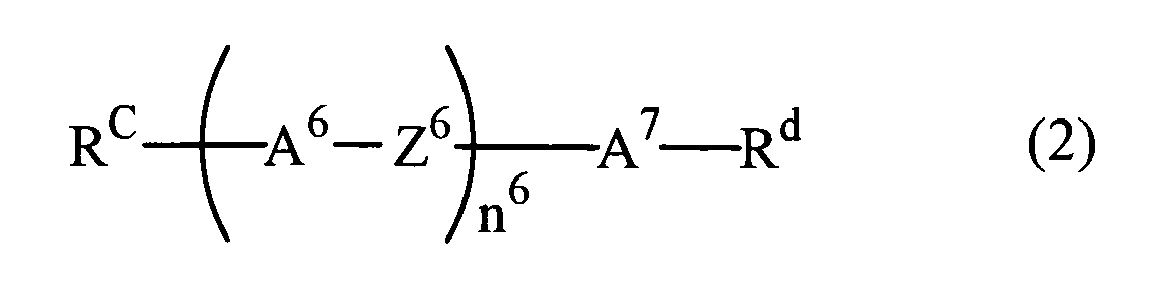
- Rc is alkyl having 1 to 10 carbon atoms, wherein any -CH2- in the alkyl can be replaced by -O-;
- Rd is halogen or -CN;
- A6 is a benzene ring or a cyclohexane ring, wherein any hydrogen in these rings can be replaced by fluorine, and A7 is a benzene ring;
- Z6 is a single bond or -COO-; and
- n6 is 1,

- and wherein in the formula (3):
- Re is alkyl having 1 to 10 carbon atoms, wherein any -CH2- in the alkyl can be replaced by -O-, -CH=CH- or -C=C-;
- Xa is fluorine or -CN;
- Z12 is -COO-; and
- L8 to L11 are each independently hydrogen or fluorine, wherein at least two of them are fluorine, and at least one of L10 and L11 is fluorine,
- and wherein the chiral dopants comprise one or more compounds represented by the following formulae (K2-5) to (K2-8):


- the clearing point T1, the clearing point T2 and the clearing point Tx of the liquid crystal composition satisfy the following conditions:


and - an optically isotropic liquid crystal phase has an optically isotropic phase which does not show diffracted light with two or more colors.
- [31] A liquid crystal element, in which an electrode is placed on one or both surfaces thereof, and which has a liquid crystal composition placed between substrates and an electric field applying means for applying electric field on the liquid crystal composition via the electrode, wherein the liquid crystal composition is that according to any one of items [1] to [30].
- [32] A liquid crystal element, in which an electrode is placed on one or both surfaces thereof, and which has: a pair of substrates, at least one of which is transparent; a liquid crystal composition placed between the substrates; and polarization plates placed on the external sides of the substrates, and which has an electric field applying means for applying electric field on the liquid crystal composition via the electrode, wherein the liquid crystal composition is that according to any one of items [1] to [30].
- [33] The liquid crystal element according to item [32], wherein the electrode is constituted on at least one of the pair of substrates so that electric field can be applied in at least two directions.
- [34] The liquid crystal element according to item [32], wherein the electrode is constituted on one or both of the pair of substrates placed in parallel with each other so that electric field can be applied in at least two directions.
- [35] The liquid crystal element according to any one of items [31] to [34], wherein: the electrode is placed in a matrix state to constitute a pixel electrode; each pixel has an active element; and the active element is a thin film transistor (TFT).
- [36] A liquid crystal composition, which comprises a compound 1 having the clearing point T1 and a compound 2 having the clearing point T2, and whose clearing point is Tx, the liquid crystal composition being used in an element driven in a state of an optically isotropic liquid crystal phase,
wherein:- the liquid crystal composition comprises 10 to 80 wt% of compound 1 and 20 to 90 wt% of compound 2; and
- the clearing point T1, the clearing point T2 and the clearing point Tx of the liquid crystal composition satisfy the following conditions:


- [37] A liquid crystal composition, which is a component of a liquid crystal composition used in an element driven in a state of an optically isotropic liquid crystal phase, wherein the difference between the upper limit and the lower limit of a temperature allowing coexistence of a chiral nematic phase and a non-liquid crystalline isotropic phase is 3°C to 150°C.
- [38] The liquid crystal composition according to item [36], wherein the difference between the upper limit and the lower limit of a temperature allowing coexistence of a chiral nematic phase and a non-liquid crystalline isotropic phase is 3°C to 150°C.
- [39] The liquid crystal composition according to item [36] or [38],
wherein:- the compound 1 is represented by the following general formula (1):

- Ra is hydrogen or alkyl having 1 to 20 carbon atoms, wherein any -CH2- in the alkyl can be replaced by -O-, -S-, -COO-, -OCO-, -CH=CH-, -CF=CF-, or -C≡C-, and any hydrogen in the alkyl group can be replaced by halogen;
- Rb is hydrogen, halogen, -CN, -N=C=O, -N=C=S, -CF3, -OCF3, or alkyl having 1 to 20 carbon atoms, wherein: any -CH2- in the alkyl can be replaced by -O-, -S-, -COO-, -OCO-, -CH=CH-, -CF=CF-, or -C≡C-; any hydrogen in the alkyl can be replaced by halogen; and -CH3 in the alkyl can be replaced by -CN;
- A1 to A5 are each independently an aromatic or nonaromatic 3- to 8-membered ring or a condensed ring having 9 or more carbon atoms, wherein: any hydrogen in these rings can be replaced by halogen, alkyl having 1 to 3 carbon atoms or alkyl halide having 1 to 3 carbon atoms; any -CH2- in the rings can be replaced by -O-, -S-, or -NH-; any -CH= in the rings can be replaced by -N=; and A1 to A5 are not tetrahydropyran rings;
- Z1 to Z4 are each independently a single bond or alkylene having 1 to 8 carbon atoms, wherein any -CH2- in the alkylene can be replaced by -O-, -S-, -COO-, -OCO-, -CSO-, -OCS-, -N=N-, -CH=N-, -N=CH-, -N(O)=N-, -N=N(O)-, -CH=CH-, -CF=CF- or -C≡C-, and any hydrogen can be replaced by halogen; and
- n1 to n3 are each independently 0 or 1; when Rb is hydrogen or fluorine, n2 and n3 are 1; when Z4 is -COO-, n2 and n3 are 1; and only when at least one of A4 and A5 is a condensed ring having 9 or more carbon atoms, all of n1 to n3 can be 0; and
- the clearing point of the compound is 150°C to 400°C.
- the compound 1 is represented by the following general formula (1):
- [40] The liquid crystal composition according to item [36], [38] or [39], wherein the compound 2 is represented by the following general formula (2):

- Rc is hydrogen or alkyl having 1 to 20 carbon atoms, wherein any -CH2- in the alkyl can be replaced by -O-, -S-, -COO-, -OCO-, -CH=CH-, -CF=CF- or -C≡C-, and any hydrogen in the alkyl can be replaced by halogen;
- Rd is halogen, -CN, -N=C=O, -N=C=S, -CF3, -OCF3, -C≡C-CN, or -C≡C-CF3;
- A6 and A7 are each independently an aromatic or nonaromatic 3- to 8-membered ring or a condensed ring having 9 or more carbon atoms, wherein any hydrogen in the rings can be replaced by halogen, alkyl having 1 to 3 carbon atoms or alkyl halide having 1 to 3 carbon atoms; any -CH2- in the rings can be replaced by -O-, -S-, or -NH-; and any -CH= in the rings can be replaced by -N=;
- Z6 is a single bond or alkylene having 1 to 8 carbon atoms, wherein any -CH2-in the alkylene can be replaced by -O-, -S-, -COO-, -OCO-, -CSO-, -OCS-, -N=N-, -CH=N-, -N=CH-, -N(O)=N-, -N=N(O)-, -CH=CH-, -CF=CF- or -C≡C-, and any hydrogen in the alkylene can be replaced by halogen; and
- n6 is 0 or 1; and when A7 is a condensed ring having 9 or more carbon atoms, n6 is 0.
- [41] The liquid crystal composition according to any one of items [36] and [38] to [40], wherein the compound 2 is represented by the following general formula (3):

- Re is alkyl having 1 to 10 carbon atoms, wherein any -CH2- in the alkyl can be replaced by -O-, -S-, -COO-, -OCO-, -CH=CH-, -CF=CF- or -C≡C-, and any hydrogen in the alkyl can be replaced by halogen;
- Xa is fluorine, chlorine, -CN, -N=C=S, -CF3, -C≡C-CN or -C≡C-CF3;
- Z12 is a single bond, -COO- or -C≡C-; and
- L8 to L11 are each independently hydrogen or fluorine.
- The liquid crystal composition of the preferred embodiment of the invention can exhibit an optically isotropic liquid crystal phase in a wide temperature range without substantially including a high-molecular substance. Moreover, a large electric birefringence (including the Kerr effect with a high Kerr constant) can be observed in the liquid crystal composition of the preferred embodiment of the invention. Furthermore, the response time of the liquid crystal composition of the preferred embodiment of the invention is very short, and the composition can be homochromatic. In the liquid crystal composition of the preferred embodiment of the invention, birefringence, which remains even if returning to a state, in which electric field is not applied, after application of high electric field, can be reduced. Further, the liquid crystal composition of the preferred embodiment of the invention can be suitably used for liquid crystal elements such as display elements and the like based on these effects.
-
-
FIG 1 shows polarization microscope images of liquid crystal composition B-2 in the lowered temperature process. -
FIG 2 shows a comb-like electrode substrate used in Example 5. -
FIG 3 shows an optical system used in Example 5. - The liquid crystal composition of the invention is an optically isotropic liquid crystal composition used in an element driven in a state of an optically isotropic liquid crystal phase. That is, the liquid crystal composition of the invention is a liquid crystal composition used in a liquid crystal element, and the liquid crystal composition can be used in a liquid crystal element in a liquid crystal phase showing optically isotropic property (e.g., a blue phase).
- A liquid crystal composition which exhibits a nematic phase (except for a chiral nematic phase) does not exhibit an optically isotropic liquid crystal phase at any temperature. Therefore, the liquid crystal composition of the invention is a composition which does not exhibit the nematic phase at any temperature.
- Further, the nematic phase and the chiral nematic phase are not optically isotropic phases. Therefore, the liquid crystal composition of the invention used in an element driven in the state of the optically isotropic liquid crystal phase does not include liquid crystal compositions used in elements driven in the state of the nematic phase or the chiral nematic phase.
- For example, the liquid crystal composition of the invention is a liquid crystal composition A, which is obtained by mixing a compound 1 represented by formula (1) and a compound 2 represented by formula (2) or (3), or a liquid crystal composition B, which is obtained by further adding a specific amount of chiral dopants to the composition, and which exhibits an optically isotropic liquid crystal phase. However, the liquid crystal composition A may contain chiral dopants in a range in which an optically isotropic liquid crystal phase is not exhibited.
- In the liquid crystal composition A of the invention, the compound 1 may consist of one compound represented by formula (1) or a plurality of compounds represented by formula (1). Similarly, the compound 2 may consist of one compound represented by formula (2) or (3) or a plurality of compounds represented by formula (2) or (3).
- Further, in the specification, the liquid crystal composition refers to a composition having a liquid crystal phase or a composition which does not significantly decrease the liquid crystal phase-non-liquid crystalline isotropic phase transition temperature when mixed with a liquid crystal material.
- When a liquid crystalline compound or a liquid crystalline composition does not exhibit the liquid crystal phase, a method for calculating a liquid crystal phase-non-liquid crystalline isotropic phase transition point using an extrapolation method is employed as described below. This extrapolation method can be applied to a compound or a composition whose liquid crystal phase-non-liquid crystalline isotropic phase transition point is higher than the decomposition temperature of liquid crystal.
- In the liquid crystal composition A of the invention, the clearing points (T1) and (T2) of the compounds 1 and 2 contained in the liquid crystal composition A and the clearing point (Tx) of the liquid crystal composition A preferably satisfy the following formulae:


More preferably, these clearing points satisfy the following formulae:

- In this regard, the clearing point means a temperature at which a compound or composition exhibits a non-liquid crystalline isotropic phase in the elevated temperature process. Specific examples of clearing points include N-I point, which is a phase transition point from a nematic phase to a non-liquid crystalline isotropic phase. In the case of the liquid crystal composition of the invention, a coexisting state of a non-liquid crystalline isotropic phase and a liquid crystal phase may be exhibited. In this case, a temperature at which a non-liquid crystalline isotropic phase is initially appeared in the elevated temperature process is defined as a clearing point. Further, a clearing point of a compound which does not exhibit a liquid crystal phase, i.e., a compound having K-I point, is K-I point or lower. According to need, the method for calculating a liquid crystal phase-non-liquid crystalline isotropic phase transition point using the extrapolation method as described below can be employed.
- The compound 1 preferably has a relatively high clearing point. Specifically, the compound 1 is preferably a compound represented by formula (1). In formula (1): Ra is hydrogen or alkyl having 1 to 20 carbon atoms; any -CH2- in the alkyl can be replaced by -O-, -S-, -COO-, -OCO-, -CH=CH-, -CF=CF- or -C=C-; and any hydrogen in the alkyl group can be replaced by halogen. Among them, Ra is preferably alkyl having 1 to 10 carbon atoms, and any -CH2- in the alkyl can be replaced by -O-, -S-, -COO-, -OCO-, -CH=CH- or -C≡C-. More preferably, Ra is alkyl having 1 to 10 carbon atoms, and any -CH2- in the alkyl can be replaced by -CH=CH- or -C≡C-. Among them, Ra is most preferably alkyl having 1 to 10 carbon atoms or alkoxy.
- In formula (1): Rb is hydrogen, halogen, -CN, -N=C=O, -N=C=S, -CF3, -OCF3 or alkyl having 1 to 20 carbon atoms; any -CH2- in the alkyl can be replaced by -O-, -S-, -COO-, -OCO-, -CH=CH-, -CF=CF- or -C≡C-; any hydrogen in the alkyl can be replaced by halogen; and -CH3 in the alkyl can be replaced by -CN. Among them, Rb is preferably halogen, -CN, -N=C=O, -N=C=S, -CF3, -OCF3 or alkyl having 1 to 20 carbon atoms; any -CH2- in the alkyl can be replaced by -O-, -CH=CH- or -C≡C-; any hydrogen in the alkyl can be replaced by halogen; and -CH3 in the alkyl can be replaced by -CN. Rb is more preferably fluorine, chlorine, -CN, -N=C=S or alkyl having 1 to 20 carbon atoms, and any -CH2- in the alkyl can be replaced by -O-, -CH=CH- or -C≡C-.
- In formula (1), A1 to A5 are each independently an aromatic or nonaromatic 3-to 8-membered ring or a condensed ring having 9 or more carbon atoms, wherein: any hydrogen in these rings can be replaced by halogen, alkyl having 1 to 3 carbon atoms or alkyl halide having 1 to 3 carbon atoms; any -CH2- in the rings can be replaced by -O-, -S- or -NH-; any -CH= in the rings can be replaced by -N=; and A1 to A5 are not tetrahydropyran rings. Among them, preferably, A1 to A5 are each independently a benzene ring, a naphthalene ring, a dioxane ring or a cyclohexane ring, wherein any hydrogen in these rings can be replaced by halogen, alkyl having 1 to 3 carbon atoms or alkyl halide having 1 to 3 carbon atoms, and any -CH2- in the rings can be replaced by -O- or -S-, and any -CH= can be replaced by -N=. More preferably, A1 to A5 are each independently a benzene ring, a naphthalene ring, a dioxane ring or a cyclohexane ring, wherein any hydrogen in the benzene ring or the naphthalene ring can be replaced by fluorine, chlorine, methyl or methyl halide; any -CH2- can be replaced by -O- or -S-; and any -CH= can be replaced by -N=. Among them, most preferably, A1 to A5 are each independently a benzene ring, a dioxane ring or a cyclohexane ring, wherein any hydrogen in the benzene ring can be replaced by fluorine.
- In formula (1), Z1 to Z4 are each independently a single bond or alkylene having 1 to 8 carbon atoms, wherein any -CH2- in the alkylene can be replaced by -O-, -S-, -COO-, -OCO-, -CSO-, -OCS-, -N=N-, -CH=N-, -N=CH-, -N(O)=N-, -N=N(O)-, -CH=CH-, -CF=CF- or -C≡C-, and any hydrogen can be replaced by halogen. Among them, preferably, Z1 to Z4 are each independently a single bond or alkylene having 1 to 4 carbon atoms, wherein any -CH2- in the alkylene can be replaced by -O-, -S-, -COO-, -OCO-, -CSO-, -OCS-, -CH=CH-, -CF=CF- or -C≡C-, and any hydrogen can be replaced by halogen. More preferably, Z1 to Z4 are each independently a single bond or -C≡C-.
- In formula (1), n1 to n3 are each independently 0 or 1, wherein: n2 and n3 are 1 when Rb is hydrogen or fluorine; n2 and n3 are 1 when Z4 is -COO-; and all of n1 to n3 may be 0 only when at least one of A4 and A5 is a condensed ring having 9 or more carbon atoms. Among them, preferably, n1 to n3 are each independently 0 or 1, wherein n2 and n3 are 1 when Rb is hydrogen or fluorine, and all of n1 to n3 may be 0 only when at least one of A4 and A5 is a condensed ring having 9 or more carbon atoms. Among them, more preferably, n1 to n3 are each independently 0 or 1, wherein n2 and n3 are 1 when Rb is hydrogen or fluorine, and all of n1 to n3 may be 0 only when at least one of A4 and A5 is a condensed ring having 9 or more carbon atoms.
- The compound represented by formula (1) preferably has a clearing point of 150°C to 400°C, and more preferably has a clearing point of 200°C to 350°C. When the clearing point is lower than 150°C, it is disadvantageous in terms of satisfying the relation between the clearing point of the compound 1 (T1) and the clearing point of the liquid crystal composition A (Tx) (T1-Tx ≥ 100°C). When the clearing point is higher than 400°C, the compatibility may be decreased depending on other compounds to be combined therewith, and the lower limit of temperature of the liquid crystal phase may be raised, wherein crystal is separated out at a low temperature.
- The compound 2 preferably has a low clearing point and a large value of dielectric anisotropy. Specifically, the compound 2 is preferably represented by formula (2) or (3).
- In formula (2), Rc is hydrogen or alkyl having 1 to 20 carbon atoms, wherein any -CH2- in the alkyl can be replaced by -O-, -S-, -COO-, -OCO-, -CH=CH-, -CF=CF-or -C≡C-, and any hydrogen in the alkyl can be replaced by halogen. Among them, preferably, Rc is alkyl having 1 to 10 carbon atoms, wherein any -CH2- in the alkyl can be replaced by -O-, -S-, -COO-, -OCO-, -CH=CH- or -C≡C-. More preferably, Rc is alkyl having 1 to 10 carbon atoms, wherein any -CH2- in the alkyl can be replaced by -O-, -CH=CH- or -C≡C-. Most preferably, Rc is alkyl having 1 to 10 carbon atoms, wherein any -CH2- in the alkyl can be replaced by -O-.
- In formula (2), Rd is halogen, -CN, -N=C=O, -N=C=S, -CF3, -OCF3, -C≡C-CN or -C≡C-CF3. Among them, Rd is preferably halogen, -CN, -N=C=S, -CF3, -C=C-CN or -C≡C-CF3.
- In formula (2), A6 and A7 are each independently an aromatic or nonaromatic 3-to 8-membered ring or a condensed ring having 9 or more carbon atoms, wherein any hydrogen in these rings can be replaced by halogen, alkyl having 1 to 3 carbon atoms or alkyl halide having 1 to 3 carbon atoms; any -CH2- in the rings can be replaced by -O-, -S- or -NH-; and any -CH= can be replaced by -N=.
- Among them, more preferably, A6 and A7 are each independently a benzene ring, a naphthalene ring or a cyclohexane ring, wherein any hydrogen in these rings can be replaced by halogen, alkyl having 1 to 3 carbon atoms or alkyl halide having 1 to 3 carbon atoms; any -CH2- in the rings can be replaced by -O- or -S-; and any -CH= can be replaced by -N=. Even more preferably, A6 and A7 are each independently a benzene ring, a naphthalene ring or a cyclohexane ring, wherein any hydrogen in these rings can be replaced by fluorine, chlorine, methyl or methyl halide; any -CH2- in the rings can be replaced by -O- or -S-; and any -CH= can be replaced by -N=. Most preferably, A6 and A7 are each independently a benzene ring, a dioxane ring or a cyclohexane ring, wherein any hydrogen in the benzene ring can be replaced by fluorine.
- In formula (2), Z6 is a single bond or alkylene having 1 to 8 carbon atoms, wherein any -CH2- in the alkylene can be replaced by -O-, -S-, -COO-, -OCO-, -CSO-, -OCS-, -N=N-, -CH=N-, -N=CH-, -N(O)=N-, -N=N(O)-, -CH=CH-, -CF=CF- or -C≡C-, and any hydrogen in the alkylene can be replaced by halogen. Among them, Z6 is preferably a single bond or alkylene having 1 to 4 carbon atoms, wherein any -CH2- in the alkylene can be replaced by -O-, -S-, -COO-, -OCO-, -CSO-, -OCS-, -CH=CH-, -CF=CF- or -C=C-, and any hydrogen in the alkylene can be replaced by halogen. Z6 is more preferably a single bond, -COO-, -CF2O- or -C≡C-. Most preferably, Z6 is a single bond or -COO-.
- In formula (2), n6 is 0 or 1, wherein n6 is 0 when A7 is a condensed ring having 9 or more carbon atoms. Among them, preferably, n6 is 0 or 1, wherein n6 is 0 when A7 is a naphthalene ring. More preferably, n6 is 0 or 1, wherein n6 is 0 when A7 is a naphthalene ring. Most preferably, n6 is 0 or 1.
- In formula (3), Re is alkyl having 1 to 10 carbon atoms, wherein any -CH2- in the alkyl can be replaced by -O-, -S-, -COO-, -OCO-, -CH=CH-, -CF=CF- or -C=C-, and any hydrogen in the alkyl can be replaced by halogen. Among them, Re is preferably alkyl having 1 to 10 carbon atoms, wherein any -CH2- in the alkyl can be replaced by -O-, -CH=CH- or -C≡C-.
- In formula (3), Xa is fluorine, chlorine, -CN, -N=C=S, -CF3, -C≡C-CN or -C≡C-CF3.
- In formula (3), Z12 is a single bond, -COO- or -C≡C-, and among them, -COO-is preferable.
- In formula (3), L8 to L11 are each independently hydrogen or fluorine. Among them, preferably, L8 to L11 are each independently hydrogen or fluorine, wherein at least two of them are fluorine.
- When the clearing point of the compound 1 is 150 to 250°C, preferably, the compound 1 is contained in an amount of 10 to 80 wt% and the compound 2 is contained in an amount of 20 to 90 wt% in the liquid crystal composition A. More preferably, the compound 1 is contained in an amount of 30 to 60 wt% and the compound 2 is contained in an amount of 30 to 70 wt%. When the clearing point of the compound 1 is 250 to 400°C, preferably, the compound 1 is contained in an amount of 5 to 70 wt% and the compound 2 is contained in an amount of 30 to 95 wt% in the liquid crystal composition A. As described above, a plurality of compounds represented by formula (1) can be contained in the liquid crystal composition of the invention as the compound 1, and similarly, a plurality of compounds represented by formula (2) can be contained as the compound 2. Therefore, for example, when a plurality of compounds represented by formula (1) are contained, the total amount of the compounds represented by formula (1) is 10 to 80 wt% (or 5 to 70 wt%).
- The liquid crystal composition A is a liquid crystal composition, which exhibits the coexistence state of the nematic phase and the non-liquid crystalline isotropic phase in the lowered temperature process when no chiral dopant is contained, and which exhibits the coexistence state of the chiral nematic phase and the non-liquid crystalline isotropic phase in the lowered temperature process when the chiral dopants are contained. Further, the liquid crystal composition A is a composition which does not exhibit an optically isotropic liquid crystal phase. The coexistence state of the (chiral) nematic phase and the non-liquid crystalline isotropic phase can be confirmed, for example, by observation using a polarization microscope. These coexistence states are not caused by temperature gradient with respect to the liquid crystal composition.
- In the liquid crystal composition of the invention, with respect to the liquid crystal composition A which allows coexistence of the (chiral) nematic phase and the non-liquid crystalline isotropic phase, a temperature range allowing coexistence of the (chiral) nematic phase and the non-liquid crystalline isotropic phase is preferably wide. Specifically, the difference between the upper limit and the lower limit of a temperature allowing the coexistence of these phases is more preferably 3 to 150°C. When the temperature range allowing the coexistence of these phases is wide, the liquid crystal composition B, which is obtained by further adding the chiral dopants, tends to have an optically isotropic liquid crystal phase in a wide temperature range.
- When the chiral dopants are added to the liquid crystal composition A, in which the nematic phase and the non-liquid crystalline isotropic phase coexist in a wide temperature range, and which does not comprise the chiral dopants, the liquid crystal composition A, in which the chiral nematic phase and the non-liquid crystalline isotropic phase coexist in a wide temperature range, can be easily obtained.
- The pitch of the chiral nematic phase, which does not coexist with the non-liquid crystalline isotropic phase in the liquid crystal composition A, is 700 nm or more. As described later, when the chiral dopants are added, the liquid crystal composition B having a shorter pitch can be obtained.
- The liquid crystal composition B is a composition which exhibits an optically isotropic liquid crystal phase. For example, the liquid crystal composition B can be obtained by further adding the chiral dopants to the liquid crystal composition A.
- A liquid crystal composition, in which the chiral dopants are added in an amount of 1 to 40 wt%, preferably in an amount of 5 to 15 wt% of the total weight of the liquid crystal composition B, tends to have an optically isotropic liquid crystal phase, and therefore is preferable, though it depends on the composition of the liquid crystal composition A, the type of the chiral dopants to be further added and the like.
- In the step of producing the liquid crystal composition B, which is characterized by addition of the chiral dopants to the liquid crystal composition A, the chiral dopants which can be contained in the liquid crystal composition A in advance and the chiral dopants which are further added in order to obtain the liquid crystal composition B may be the same or different.
- The chiral dopants contained in the liquid crystal composition B is preferably a compound having a strong helical twisting power. In the case of a compound having a strong helical twisting power, an adding amount thereof required to obtain a desired pitch can be decreased, and therefore increase in drive voltage can be suppressed, and it is practically advantageous. Specifically, compounds represented by the above-described formulae (K1) to (K5) are preferable.
- In formulae (K1) to (K5): each RK is independently hydrogen, halogen, -CN, -N=C=O, -N=C=S or alkyl having 1 to 20 carbon atoms, wherein any -CH2- in the alkyl can be replaced by -O-, -S-, -COO-, -OCO-, -CH=CH-, -CF=CF- or -C≡C-, and any hydrogen in the alkyl can be replaced by halogen; each A is independently an aromatic or nonaromatic 3- to 8-membered ring or a condensed ring having 9 or more carbon atoms, wherein any hydrogen in these rings can be replaced by halogen, alkyl having 1 to 3 carbon atoms or haloalkyl having 1 to 3 carbon atoms; any -CH2- can be replaced by -O-, -S- or -NH-, and any -CH= can be replaced by -N=; each Z is independently a single bond or alkylene having 1 to 8 carbon atoms, wherein any -CH2- can be replaced by -O-, -S-, -COO-, -OCO-, -CSO-, -OCS-, -N=N-, -CH=N-, -N=CH-, -N(O)=N-, -N=N(O)-, -CH=CH-, -CF=CF- or -C≡C-, and any hydrogen can be replaced by halogen; X is a single bond, -COO-, -CH2O-, -CF2O- or -CH2CH2-; and m is 1 to 4.
- Among them, the chiral dopants added to the liquid crystal composition B are preferably represented by formulae (K2-1) to (K2-8) included in formula (K2) and formulae (K5-1) to (K5-3) included in formula (K5) (in the formulae, each RK is independently alkyl having 3 to 10 carbon atoms, wherein -CH2- adjacent to the ring in the alkyl can be replaced by -O-, and any -CH2- can be replaced by -CH=CH-).
- The chiral dopants are contained preferably in an amount of 1 to 40 wt%, more preferably in an amount of 3 to 25 wt%, and most preferably in an amount of 5 to 15 wt% of the total weight of the liquid crystal composition B.
- The liquid crystal composition B has an optically isotropic liquid crystal phase. "A liquid crystal composition has optical isotropy" means that the composition shows optically isotropic nature since liquid crystal molecular alignment is macroscopically isotropic, but liquid crystalline order is microscopically present. The pitch based on the liquid crystalline order, which the liquid crystal composition B microscopically has, is preferably 700 nm or less, more preferably 500 nm or less, and most preferably 350 nm or less.
- The term "non-liquid crystalline isotropic phase" means a generally-defined isotropic phase, i.e., a disordered phase, wherein, if the phase is generated by a region whose local order parameter is not zero, the cause thereof is fluctuation. For example, an isotropic phase which is exhibited in the high temperature side of the nematic phase corresponds to the non-liquid crystalline isotropic phase in the specification. The same definition is applied to the chiral liquid crystal in the specification. Further, the term "optically isotropic liquid crystal phase" as used herein refers to a phase which exhibits an optically isotropic (not fluctuant) liquid crystal phase. Examples thereof include a phase which exhibits a platelet texture (blue phase in a limited sense).
- Regarding the liquid crystal composition B of the invention, a platelet texture, which is typically found in a blue phase, is sometimes not observed in a liquid crystal phase by means of a polarization microscope though it is optically isotropic. For this reason, in the specification, only phases which exhibit a platelet texture are referred to as "blue phase" (blue phase in a limited sense), and they are distinguished from optically isotropic liquid crystal phases which do not show diffracted light with two or more colors.
- In general, the blue phase is classified into three types (blue phase I, blue phase II and blue phase III). All of the three types of blue phases are optically active and isotropic. In the blue phases I and II, 2 or more types of diffracted lights attributed to Bragg reflections from different lattice planes are observed.
- A state in which an optically isotropic liquid crystal phase does not show diffracted light with two or more colors means that a platelet texture, which is observed in blue phases I and II, is not observed in the phase, and that the phase is generally in one color. In optically isotropic liquid crystal phases which do not show diffracted light with two or more colors, uniformity of color tone is not required.
- Optically isotropic liquid crystal phases which do not show diffracted light with two or more colors have the advantages that the intensity of reflected light caused by Bragg reflection is suppressed and that it is shifted to the low-wavelength side.
- Further, the problem of color is sometimes raised when a liquid crystal material which reflects visible light is utilized as a display element. However, in the case of liquid crystal which does not show diffracted light with two or more colors, reflection wavelength is shifted to the low-wavelength side, and therefore reflection of visible light is allowed to disappear with a pitch that is longer than that of the blue phase in the limited sense (a phase which exhibits a platelet texture).
- The longer the pitch, the larger the electric birefringence of the optically isotropic liquid crystal phase. Therefore, the electric birefringence can be increased. In this state, when electric field is applied to the liquid crystal composition B, rapid response without residual image can be obtained.
- Other compounds such as high-molecular substances can be further added to the liquid crystal composition of the invention in a range in which properties of the composition is not affected thereby. The liquid crystal composition of the invention may contain, for example, a dichroism pigment, a photochromic compound or the like in addition to the high-molecular substances.
- Positive/negative of the dielectric anisotropy of the liquid crystal composition of the invention is not particularly limited, but positive is preferable. With respect to the absolute value of the value of dielectric anisotropy of the liquid crystal material (Δε) and the value of optical anisotropy (Δn), the higher these values, the higher the electric birefringence, and therefore these values are preferably as high as possible.
- The following examples are for illustrative purposes only and are not intended, nor should they be interpreted to, limit the scope of the invention.
- In the examples of the specification, "K" represents the crystal phase; "I" represents the non-liquid crystalline isotropic phase; "N" represents the nematic phase; "N*" represents the chiral nematic phase; "BP" represents the blue phase; and "BPX" represents the optically isotropic liquid crystal phase in which diffracted light with two or more colors is not observed. Coexistence state of two phases is sometimes described in the following form: (N*+I), (N*+BPX), etc. Specifically, (N*+I) represents a phase in which the non-liquid crystalline isotropic phase and the chiral nematic phase coexist, and (N*+BPX) represents a phase, in which the optically isotropic liquid crystal phase in which diffracted light with two or more colors is not observed and the chiral nematic phase coexist. "Un" represents an unconfirmed phase which is not optically isotropic.
- In the specification, I-N phase transition point is sometimes referred to as N-I point, and I-N* transition point is sometimes referred to as N*-I point. Further, I-BP phase transition point is sometimes referred to as BP-I point.
- In the examples of the specification, measurement/calculation of values of physical properties and the like is made according to the method described in the Standard of Electronic Industries Association of Japan, EIAJ·ED-2521A, unless otherwise indicated. Specific methods of measurement, calculation and the like are as described below.
- A sample was placed on a hotplate of a melting-point measuring apparatus equipped with a polarization microscope. Initially, under crossed nicols, temperature was elevated to the point at which the sample becomes the non-liquid crystalline isotropic phase, and thereafter temperature was lowered at the rate of 1°C/minute, and the chiral nematic phase or the optically anisotropic phase was allowed to be completely exhibited. Phase transition temperature in the process was measured. Next, temperature was elevated at the rate of 1°C/minute, and phase transition temperature in this process was measured. When it was difficult to determine the phase transition point in the optically isotropic liquid crystal phase in dark field under crossed nicols, a polarization plate was inclined at an angle of 1 to 10° from the state of the crossed nicols to measure the phase transition temperature.
- A nematic liquid crystal composition consisting of 85 wt% of mother liquid crystal exhibiting the nematic phase and 15 wt% of liquid crystalline compound or liquid crystalline composition is prepared. Linear extrapolation was made using the liquid crystal phase-non-liquid crystalline isotropic phase transition points of the mother liquid crystal and the liquid crystalline compound or liquid crystalline composition to determine the liquid crystal phase-non-liquid crystalline isotropic phase transition point of the liquid crystalline compound or the liquid crystalline composition.
- A sample having the nematic phase was put into a glass bottle, and it was held in a freezer at 0°C, -10°C, -20°C, -30°C and -40°C for 10 days, and thereafter the liquid crystal phase was observed. For example, regarding the case where the nematic phase remained in the sample at -20°C and it changed to crystal or smectic phase at -30°C, it was described as TC ≤ -20°C. The lower limit of temperature of the nematic phase is sometimes abbreviated as "lower limit of temperature".
- An E-type viscometer was used to measure viscosity.
- Measurement was conducted with an Abbe refractometer, in which a polarization plate is provided to an eyepiece, using light having a wavelength of 589 nm. After the surface of a main prism was rubbed in one direction, the sample was dropped on the main prism. The refractive index n // was measured when the direction of polarized light was parallel to the direction of rubbing. The refractive index n┴ was measured when the direction of polarized light was perpendicular to the direction of rubbing. Calculation was made using the following equation: Δn = n // - n┴.
- The sample was put into a TN cell in which the gap between two glass substrates was about 9 µm and the twist angle was 80°. A sine wave (10V, 1kHz) was applied on the cell, and 2 seconds later, the permittivity of liquid crystal molecules in the major axis direction (ε//) was measured. A sine wave (0.5V, 1kHz) was applied on the cell, and 2 seconds later, the permittivity of liquid crystal molecules in the minor axis direction (ε┴) was measured. The value of dielectric anisotropy was calculated using the following equation: Δε = ε // - ε┴.
- The sample was put into a liquid crystal cell treated to have a homeotropic alignment in which the gap between two glass substrates was about 9 µm. A sine wave (0.5V 1kHz) was applied on the cell, and 2 seconds later, the permittivity (ε//) was measured. Further, the sample was put into a liquid crystal cell treated to have a homogeneous alignment in which the gap between two glass substrates was about 9 µm. A sine wave (0.5V, 1kHz) was applied on the cell, and 2 seconds later, the permittivity (ε┴) was measured. The value of dielectric anisotropy was calculated using the following equation: Δε = ε // - ε┴.
- The TN element used in the measurement had a polyimide-aligned film, and the cell gap was 6 µm. After putting the sample into the element, it was sealed with an adhesive which is polymerized by ultraviolet. A pulse voltage (5V for 60 µs) was applied on the TN element for charging. Attenuating voltage was measured for 16.7 msec using a high-speed voltmeter, and an area between the voltage curve and the horizontal axis in a cycle was calculated. Further, from the wave pattern of voltage measured after removing the TN element, an area was similarly calculated. Voltage holding ratio was calculated by comparison between the two areas.
- Pitch length was measured using selective reflection (Handbook of Liquid Crystal, page 196 (published in 2000, Maruzen)). The selective reflection wavelength λ satisfies the following relational expression: <n>pλ = 1. <n> represents the average refractive index, which is calculated using the following formula: <n> = {(n//2 + n┴2)/2}1/2. The selective reflection wavelength was measured using a microspectrophotometer (JEOL Ltd., trade name: MSV-350). The pitch was calculated by dividing the obtained reflection wavelength by the average refractive index.
- The pitch of cholesteric liquid crystal having a reflection wavelength in a longer-wavelength region compared to visible light is proportional to the inverse number of the concentration of optically active compounds in a region where the concentration of the optically active compounds is low. Therefore, the pitch was determined by measuring pitch length of liquid crystal having a selective reflection wavelength in the visible light region at several points and applying the linear extrapolation method thereto.
- A nematic liquid crystal composition A-1 was prepared by mixing compounds represented by the following formulae (a), (b-1) to (b-5), (c) and (d) (hereinafter referred to as "compound a", etc.) in the weight ratio shown below. Specifically, the composition was prepared by mixing: a compound a having the clearing point (N-I point) of 202°C, as the compound 1 represented by the above-described formula (1); a compound c having the clearing point (N-I point) of 35.5°C, as the compound 2 represented by the above-described formula (2); a compound d having the K-I point of 49.8°C, as the compound 2 represented by the above-described formula (3); and other compounds (compound b-1 to compound b-5). Values shown at the right side of values of the weight ratio are phase transition temperatures of respective compounds. The clearing point of the compound d was 7.7°C. The clearing point of the composition was given as an extrapolation value of N-I point, which was measured after mixing 15 wt% of compound d with the mother liquid crystal ZLI-1132 (manufactured by Merck).

25% K 81.0 N 202 I 
5% K 73.0 I 
5% K 65.5 (N 62.3) I 
5% K 47.0 (N 42.2) I 
5% K 52.9 N 80.3 I 
5% K 46.2 N 57.5 I 
25% K 22.5 N 35.5 I 
25% K 49.8 I - Next, a chiral dopant ISO-60BA2 represented by the following formula was added to the liquid crystal composition A-1 to obtain liquid crystal compositions A-2, A-3, A-4, A-5, A-6 and A-7.

- Specifically, as shown in Table 1, liquid crystal compositions, in which the concentrations of chiral dopants are 7.5, 10.0, 11.0, 12.5, 16.6 and 20.0 wt% of the respective liquid crystal compositions obtained, were prepared and designated as liquid crystal compositions A-2, A-3, A-4, A-5, A-6 and A-7, respectively. Further, each of the liquid crystal compositions A-1 to A-7 was held in a cell consisting of two ITO-glasses which was not subjected to aligning treatment (cell thickness: 13 µm), and phase transition temperatures were measured using a polarization microscope.
[Table 1] Liquid crystal composition ISO-6OBA2
concentration (wt%)Conditions Phase transition temperature (°C) N*+I
temperature range (°C)BPX
temperature range (°C)A-1 0.0 L.T. (1°C / min) I-77.0-(N+I)-73-N (4.0) E.T. (1°C / min) N-75.5-(N+I)-78-I A-2 7.5 L.T. (1°C / min) I-63.7-(N*+I)-56-N* 7.7 E.T. (1°C / min) N*-60.7-(N*+I)-66.5-I A-3 10.0 L.T. (1°C / min) I-59.3-N*+I)-48-N* 11.3 E.T. (1°C / min) N*-55.4-(N*+I)-63-I A-4 11.0 L.T. (1°C I min) I-58.1-(N*+I)-45-N* 13.1 E.T. (1°C I min) N*-52.2-(N*+I)-60.5-I A-5 12.5 L.T. (1°C / min) I-55.1-(N*+I)-39-N* 16.1 E.T. (1°C / min) N*-42.4-BPX-52.2-(N*+BPX)-57-I 9.8∼14.6 A-6 16.6 L.T. (1°C / min) I-47.6-(N*+I)-43.7-BPX-28-N* E.T. (1°C / min) N*-28-BPX-48-I 20 A-7 20.0 L.T. (1°C I min) I-40.3-BPX-18-Un E.T. (1°C / min) Un-20-BPX-41-I 21 L.T.: Lowering temperature E.T.: Elevating temperature - Phase transition temperatures of the liquid crystal compositions A-1 to A-7 were as shown in Table 1. Specifically, in the case of the liquid crystal composition A-1, the difference between the upper limit (77°C) and the lower limit (73°C) of a temperature allowing coexistence of the nematic phase (N) and the non-liquid crystalline isotropic phase (I) (hereinafter also referred to as "coexistence temperature range") in the lowered temperature process of -1°C/min was 4.0°C. In the case of the liquid crystal composition A-2, the difference between the upper limit (63.7°C) and the lower limit (56°C) of a temperature allowing coexistence of the chiral nematic phase (N*) and the non-liquid crystalline isotropic phase (I) (coexistence temperature range) in the lowered temperature process of -1°C/min was 7.7°C. Similarly, coexistence temperature ranges of the liquid crystal compositions A-3 and A-4 were 11.3°C and 13.1°C, respectively.
- In the case of the liquid crystal composition A-5, in the elevated temperature process of 1°C/min, the difference between the upper limit (57 to 52.2°C) and the lower limit (42.4°C) of a temperature at which the optically isotropic liquid crystal phase was exhibited (hereinafter also referred to as "BPX temperature range") was 9.8 to 14.6°C. Similarly, BPX temperature ranges of the liquid crystal compositions A-6 and A-7 were 20°C and 21°C, respectively. Thus, the liquid crystal compositions A-5 and A-7 exhibited the optically isotropic liquid crystal phase in wide temperature ranges in the elevated temperature process.
- In optical textures of the optically isotropic liquid crystal phases of the liquid crystal compositions A-5 to A-7, platelet texture, which is found in the blue phases I and II, was not observed, and diffracted light with two or more colors was not observed. Further, in the case of the liquid crystal composition A-7, it had no color and was in dark field when observed under crossed nicols using a polarization microscope.
- The N-I point (T1), which is the clearing point of the compound a as the compound 1, was 202°C, the N-I point (Tx), which is the clearing point of the liquid crystal composition A-1, was 75.5°C, and therefore T1 - Tx = 126.5°C.
- Similarly, the N-I point (T1), which is the clearing point of the compound a as the compound 1, was 202°C, the N*-I point (Tx), which is the clearing point of the liquid crystal composition A-2, was 60.7°C, and therefore T1 - Tx = 141.3°C.
- Similarly, T1 - Tx of each of the liquid crystal compositions A-3 to A-7 was as described below.
- Liquid crystal composition A-3: T1 - Tx = 202°C - 55.4°C = 146.6°C
- Liquid crystal composition A-4: T1 - Tx = 202°C - 52.2°C = 149.8°C
- Liquid crystal composition A-5: T1 - Tx = 202°C - 57°C = 145°C
- Liquid crystal composition A-6: T1 - Tx = 202°C - 48°C = 154°C
- Liquid crystal composition A-7: T1 - Tx = 202°C - 41°C = 161°C
- A liquid crystal composition E-1 was prepared using only compounds b-1 to d (without using the compound a contained in the liquid crystal composition A-1 in Example 1). The specific composition thereof was as described below.

6.68% 
6.68% 
6.68% 
6.68% 
6.68% 
33.3% 
33.3% - Next, the liquid crystal composition E-1 was mixed with a chiral dopant ISO-60BA2 to obtain liquid crystal compositions E-2 to E-5.
- Specifically, as shown in Table 2, liquid crystal compositions, in which the concentrations of chiral dopants are 2.0, 3.5, 5.0 and 7.0 wt%, were prepared and designated as liquid crystal compositions E-2, E-3, E-4 and E-5, respectively. Further, each of the liquid crystal compositions E-1 to E-5 was held in a cell consisting of two ITO-glasses which was not subjected to aligning treatment (cell thickness: 13 µm), and phase transition temperatures were measured using a polarization microscope.
[Table 2] Liquid crystal composition ISO-6OBA2
concentration (wt%)Conditions Phase transition temperature (°C) N*+I
temperature range (°C)BPX
temperature range (°C)E-1 0.0 L.T. (1°C / min) I-31.1-(N+I)-30.8-N (0.3) E.T. (1°C / min) N-31.4-CN+I)-31.5-I E-2 2.0 L.T. (1°C / min) I-28.3-(N*+I)-27.5-N* 0.8 E.T. (1°C I min) N*-28.5-(N*+ I)-28.85-I E-3 3.5 L.T. (1°C / min) I- 26.2-(N*+I)-25.0-N* 1.2 E.T. (1°C / min) N*-26.2-(N*+ I)-26.9-I E-4 5.0 L.T. (1°C I min) I-24.8-(N*+I)-23.5-N* 1.3 E.T. (1°C / min) N*-52.2-(N*+I)-60.5-I E-5 7.0 L.T. (1°C / min) I-20.9-(BPI+I)-20.6-BPI-16.3-N* E.T. (1°C / min) N*-19.4-BPI-21.4-I 2.0 L.T.: Lowering temperature E.T.: Elevating temperature - Phase transition temperatures of the liquid crystal compositions E-1 to E-5 were as shown in Table 2. Specifically, in the case of the liquid crystal composition E-1, the difference between the upper limit (31.1°C) and the lower limit (30.8°C) of a temperature allowing coexistence of the nematic phase (N) and the non-liquid crystalline isotropic phase (I) (coexistence temperature range) in the lowered temperature process of -1°C/min was 0.3°C. In the case of the liquid crystal composition E-2, the difference between the upper limit (28.3°C) and the lower limit (27.5°C) of a temperature allowing coexistence of the chiral nematic phase (N*) and the non-liquid crystalline isotropic phase (I) (coexistence temperature range) in the lowered temperature process of -1°C/min was 0.8°C. Similarly, coexistence temperature ranges of the liquid crystal compositions E-3 and E-4 were 1.2°C and 1.3°C, respectively.
- Further, in the case of the liquid crystal composition E-5, the blue phase I was confirmed in the lowered temperature process and the elevated temperature process, and the difference between the upper limit and the lower limit of a temperature at which the blue phase I was exhibited in the elevated temperature process was 2.0°C.
- A nematic liquid crystal composition B-1 was prepared by mixing compounds represented by the following formulae (e-1), (e-2), (f) to (i) and (d) in the weight ratio described below. Specifically, the composition was prepared by mixing: compounds e-1 and e-2 having the N-I point (clearing point) of 250°C or higher, as compounds represented by the above-described formula (1); a compound d having the K-I point of 49.8°C and the clearing point (extrapolation value) of 7.7°C, as the compound 2 represented by the above-described formula (3); and compounds f to i. Values shown at the right side of values of the weight ratio are phase transition temperatures of respective compounds.

5.2% K 69.0 Sx 231.2 N >250 I 
5.2% K 64.4 Sx >250 N >250 I 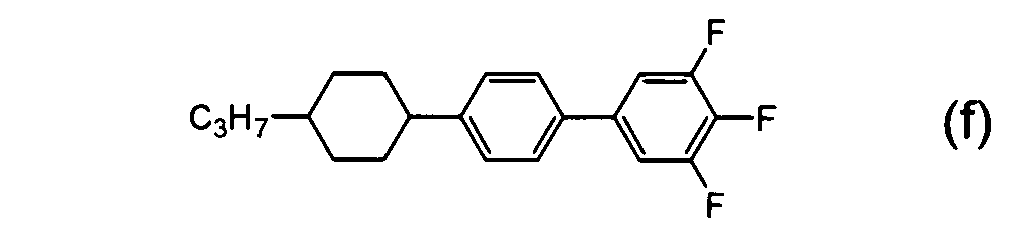
9.9% K 40.6 N (33.1) I 
9.9% K 35.7 N (33.1) I 
9.9% K 29.5 N 58.2 I 
9.9% K 39.9 N 64.7 I 
50.0% K 49.8 I - Next, a chiral dopant ISO-60BA2 was added to the liquid crystal composition B-1 to obtain liquid crystal compositions B-2, B-3, B-4 and B-5. Specifically, as shown in Table 3, liquid crystal compositions, in which the concentrations of chiral dopants are 2.9, 5.0, 8.1 and 10.0 wt%, were prepared and designated as liquid crystal compositions B-2, B-3, B-4 and B-5, respectively. Further, each of the liquid crystal compositions B-1 to B-5 was held in a cell consisting of two ITO-glasses which was not subjected to aligning treatment (cell thickness: 13 µm), and phase transition temperatures were measured using a polarization microscope.
[Table 3] Liquid crystal composition ISO-6OBA2
concentration (wt%)Conditions Phase transition temperature (°C) N*+I
temperature range(°C)BP(X)
temperature range(°C)B-1 0.0 L.T. (1°C / min) I- 60.0-(N+I)-54.0-N (6.0) E.T. (1°C / min) N-58.5-(N+I)-62-I B-2 2.9 L.T. (1°C / min) I-54.7-(N*+I)-48.6-N* 6.1 E.T. (1°C / min) *-51.5-(N*+I)-57.3-I B-3 5.0 L.T. (1°C / min) I-50.9-(N*+I)-42.9-N* 8 E.T. (1°C / min) N*-45.3-(BP+N*)-46.1-BP-51.0-(N*+I)-52.9-I 4,9 B-4 8.1 L.T. (1°C / min) I- 42.9-(BP+I)-38.0-BP-32.5-N* E.T. (1°C / min) N*-34.7-EP-41.9-(BP+I)-44.9-I 7.2∼10.2 B-5 10.0 L.T. (1°C / min) E.T. (1°C / min) N*-30.0-BP-40-I 10 L.T.: Lowering temperature E.T.: Elevating temperature - Phase transition temperatures of the liquid crystal compositions B-1 to B-5 were as shown in Table 3. Specifically, in the case of the liquid crystal composition B-1, the difference between the upper limit (60°C) and the lower limit (54°C) of a temperature allowing coexistence of the nematic phase (N) and the non-liquid crystalline isotropic phase (I) (coexistence temperature range) in the lowered temperature process of -1°C/min was 6.0°C. In the case of the liquid crystal composition B-2, the difference between the upper limit (54.7°C) and the lower limit (48.6°C) of a temperature allowing coexistence of the chiral nematic phase (N*) and the non-liquid crystalline isotropic phase (I) (coexistence temperature range) in the lowered temperature process of-1°C/min was 6.1°C.
- In the case of the liquid crystal composition B-4, in the elevated temperature process of 1°C/min, the difference between the upper limit (41.9°C to 44.9°C) and the lower limit (34.7°C) of a temperature at which the optically isotropic liquid crystal phase was exhibited (BP temperature range) was 7.2°C to 10.2°C. Similarly, the BP temperature range of the liquid crystal composition B-5 was 10°C. Thus, the liquid crystal compositions B-4 and B-5 exhibited the optically isotropic liquid crystal phase in the wide temperature range in the elevated temperature process.
- Moreover, according to the polarization microscope images of the liquid crystal composition B-2 in the lowered temperature process at 54.5°C, 52°C and 49°C (
Figure 1 ), it was found that the non-liquid crystalline isotropic phase coexists with the chiral nematic phase in the liquid crystal composition. - The N-I point (T1), which is the clearing point of the mixture of the same weight of the compounds e-1 and e-2 as the compound 1, was 270°C or higher, the N-I point (Tx), which is the clearing point of the liquid crystal composition B-1, was 56.5°C, and therefore (T1 - Tx) was 213.5°C or higher. Further, since the N*-I point (Tx), which is the clearing point of the liquid crystal composition B-2, was 51.5°C, (T1 - Tx) was 218.5°C or higher.
- Similarly, T1 - Tx of each of the liquid crystal compositions B-3 to B-5 was as described below.
- Liquid crystal composition B-3: T1 - Tx = 270°C or higher - 51.0°C = 219.0°C or higher
- Liquid crystal composition B-4: T1 - Tx = 270°C or higher - 41.9°C = 228.1°C or higher
- Liquid crystal composition B-5: T1- Tx = 270°C or higher - 40°C = 230°C or higher
- A liquid crystal composition C-1 was prepared using compounds j to I and c. The specific composition thereof was as described below.

14.1% K 60.6 N 69.2 I 
14.1% K 68.1 N 97.9 I 
28.3% K 56.3 N 106.1 I 
43.5% K 22.5 N 35.5 I - Next, a chiral dopant ISO-60BA2 was added to the liquid crystal composition C-1 to obtain liquid crystal compositions C-2 to C-5. Specifically, as shown in Table 4, liquid crystal compositions, in which the concentrations of chiral dopants are 1.9, 4.0, 6.0 and 8.1 wt%, were prepared and designated as liquid crystal compositions C-2, C-3, C-4 and C-5, respectively. Further, each of the liquid crystal compositions C-1 to C-5 was held in a cell consisting of two ITO-glasses which was not subjected to aligning treatment (cell thickness: 13 µm), and phase transition temperatures were measured using a polarization microscope.
[Table 4] Liquid crystal composition ISO-6OBA2
concentration (wt%)Conditions Phase transition temperature (°C) N*+I
temperature range(°C)BP(X)
temperature range(°C)C-1 0.0 L.T. (1°C/min) I-62.0-(N+I)-61.8-N E.T. (1°C / min) N-62.3-(N+I)-62.5-I C-2 1.8 L.T. (1°C / min) I-59.2-(N*+I)-58.7-N* 0.5 E.T. (1°C / min) N*-59.6-(N*+I)-59.8-I C-3 4.0 L.T. (1°C / min) I-55.8-(N*+I)-54.7-N* 1.2 E.T. (1°C / min) N*-55.6-EP-56.4-I 0.8 C-4 6.0 L.T. (1°C / min) I-52.5-BP-48.2-N* E.T. (1°C / min) N*-51.5-BP-53.0-I 1.5 C-5 8.1 L.T. (1°C / min) I-48.8-(BP+I)-47.88P-45.2-N* E.T. (1°C / min) N*-47.2-BP-49.0-I 1.8 L.T.: Lowering temperature E.T.: Elevating temperature - Phase transition temperatures of the liquid crystal compositions C-1 to C-5 were as shown in Table 4. Specifically, in the case of the liquid crystal composition C-1, the difference between the upper limit (62°C) and the lower limit (61.9°C) of a temperature allowing coexistence of the nematic phase (N) and the non-liquid crystalline isotropic phase (I) (coexistence temperature range) in the lowered temperature process of -1°C/min was 0.1°C.
- In the case of the liquid crystal composition C-2, the difference between the upper limit (59.2°C) and the lower limit (58.7°C) of a temperature allowing coexistence of the chiral nematic phase (N*) and the non-liquid crystalline isotropic phase (I) (coexistence temperature range) in the lowered temperature process of -1°C/min was 0.5°C. Similarly, the coexistence temperature range of the liquid crystal composition C-3 was 1.2°C.
- In the case of the liquid crystal composition C-4, the difference between the upper limit (53.0°C) and the lower limit (51.5°C) of a temperature at which the optically isotropic liquid crystal phase was exhibited (BP temperature range) in the elevated temperature process was 1.5°C. Similarly, the BP temperature range of the liquid crystal composition C-5 was 1.8°C.
- A nematic liquid crystal composition D-1 was prepared by mixing compounds represented by the following formulae (m), (n), (c) and (d) in the weight ratio described below. Specifically, the composition was prepared by mixing: compound (m) having the N-I point (clearing point) of 239°C and compound n having the N-I point of 222°C, as compound 1 represented by the above-described formula (1); compound c having the clearing point (N-I point) of 36.5°C, as compound 2 represented by the above-described formula (2); and compound d having the K-I point of 49.8°C and the clearing point (extrapolation value) of 7.7°C, as compound 2 represented by the above-described formula (3). Values shown at the right side of values of the weight ratio are phase transition temperatures of respective compounds.

20% K 130 N 239 I 
20% K 96 N 222 I 
30% K 22.5 N 35.5 I 
30% K 49.8 I - Next, a chiral dopant ISO-60BA2 was added to the liquid crystal composition D-1 to obtain liquid crystal compositions D-2, D-3 and D-4.
- Specifically, as shown in Table 5, liquid crystal compositions, in which the concentrations of chiral dopants are 9.1, 14.3 and 20.4 wt% of the respective liquid crystal compositions obtained, were prepared and designated as liquid crystal compositions D-2, D-3 and D-4, respectively. Further, each of the liquid crystal compositions D-1 to D-4 was held in a cell consisting of two ITO-glasses which was not subjected to aligning treatment (cell thickness: 13 µm), and phase transition temperatures were measured using a polarization microscope.
[Table 5] Liquid crystal composition ISO-6OBA2
concentration (wt%)Conditions Phase transition temperature (°C) N*+1
temperature range(°C)BP(X)
temperature range(°C)D-1 0.0 L.T. (1°C / min) I- 107.6-(N+I)-95.0-N (12.6) E.T. (1°C / min) N-103.7-(N+I)-110-I D-2 9.1 L.T. (1°C / min) I- 91.5-(N*+I)-72.0-N* 19.5 E.T. (1°C / min) N*-84.0-(N*+I)-96-I D-3 14.3 L.T. (1°C / min) I- 81.8-(N*+I)-51.0-N* 30.8 E.T. (1°C / min) N*-65.3-(N*+I)-90-I D-4 20.4 L.T. (1°C / min) E.T. (1°C / min) N*-37-BPX-68-(BPX+I)-71-(BPX+N*+I)-72-I 31∼35 L.T.: Lowering temperature E.T.: Elevating temperature - Phase transition temperatures of the liquid crystal compositions D-1 to D-4 were as shown in Table 5. Specifically, in the case of the liquid crystal composition D-1, the difference between the upper limit (107.6°C) and the lower limit (95°C) of a temperature allowing coexistence of the nematic phase (N) and the non-liquid crystalline isotropic phase (I) (coexistence temperature range) in the lowered temperature process of -1°C/min was 12.6°C.
- In the case of the liquid crystal composition D-2, the difference between the upper limit (91.5°C) and the lower limit (72.0°C) of a temperature allowing coexistence of the chiral nematic phase (N*) and the non-liquid crystalline isotropic phase (I) (coexistence temperature range) in the lowered temperature process of -1 °C/min was 19.5°C. Similarly, the coexistence temperature range of the liquid crystal composition D-3 was 30.8°C.
- Further, in the case of the liquid crystal composition D-4, in the elevated temperature process of 1°C/min, the difference between the upper limit (68 to 72°C) and the lower limit (37°C) of a temperature at which the optically isotropic liquid crystal phase was exhibited (BPX temperature range) was 31 to 35°C. Thus, the liquid crystal composition D-4 exhibited the optically isotropic liquid crystal phase in the wide temperature range in the elevated temperature process.
- In optical texture of the optically isotropic liquid crystal phases of the liquid crystal composition D-4, platelet texture, which is found in the blue phases I and II, was not observed, and diffracted light with two or more colors was not observed. Further, in the case of the liquid crystal composition D-4, it had no color and was in dark field when observed under crossed nicols using a polarization microscope.
- The N-I point (T1), which is the clearing point of the mixture of the same weight of the compounds m and n included in compound 1, was 230°C. The N-I point (Tx), which is the clearing point of the liquid crystal composition D-1, was 103.7°C. Therefore, (T1-Tx) was 126.3°C.
- Similarly, T1-Tx of each of the liquid crystal compositions D-3 to D-4 was as follows.
- Liquid crystal composition D-3: T1-Tx = 230°C - 65.3°C = 164.7°C
- Liquid crystal composition D-4: T1-Tx = 230°C - 68°C = 162°C
- A nematic liquid crystal composition F-1 was prepared by mixing compounds represented by the following formulae (o-1), (o-2), (o-3) and (p) in the weight ratio described below. Specifically, the composition was prepared by mixing: compounds (o-1) to (o-3) having the N-I point (clearing point) of 250°C or higher, as compounds represented by the above-described formula (1); and compound p having the K-I point of 21.4°C and the clearing point (extrapolation value) of -41.6°C, as compound 2 represented by the above-described formula (3). Values shown at the right side of values of the weight ratio are phase transition temperatures of respective compounds.

16.6% K 102.9 N 258.7 I 
16.7% K 98.4 N 255.2 I 
16.7% K 87.8 N 251.5 I 
50.0% K21.4 I - Next, a chiral dopant ISO-60BA2 was added to the liquid crystal composition F-1 to obtain liquid crystal compositions F-2 and F-3. Specifically, as shown in Table 6, liquid crystal compositions, in which the concentrations of chiral dopants are 0.8 and 10.0 wt%, were prepared and designated as liquid crystal compositions F-2 and F-3, respectively. Further, each of the liquid crystal compositions F-2 and F-3 was held in a cell consisting of two ITO-glasses which was not subjected to aligning treatment (cell thickness: 13 µm), and phase transition temperatures were measured using a polarization microscope. In this regard, the clearing point of F-3 was determined as follows: the same cell as that used in Example 4 was used; an alternating sine wave (80 V) was applied on F-3 and observation was conducted using a polarization microscope; and a temperature at which the transmission rate was rapidly decreased under the elevated temperature condition was determined as the clearing point.
[Table 6] Liquid crystal composition ISO-6OBA2
concentration (wt%)Conditions Phase transition temperature (°C) N*+ I
temperature range (°C)BP(X)
temperature range (°C)F-1 0.0 L.T. (1°C / min) I-98.7-(N+I)-85-N (13.7) E.T. (1°C / min) N-89.2-(N+I)-101-I F-2 0.8 L.T. (1°C / min) I-97.2-(N*+I)-81-N* 16.2 E.T. (1°C / min) N*-84-(N*+I)-101-I F-3 10.0 L.T. 1°C / min) E.T. (1°C / min) N*-54-(BPX or BP)-74-I 20 L.T.: Lowering temperature E.T.: Elevating temperature - Phase transition temperatures of the liquid crystal compositions F-1 to F-3 were as shown in Table 6. Specifically, in the case of the liquid crystal composition F-1, the difference between the upper limit (98.7°C) and the lower limit (85°C) of a temperature allowing coexistence of the nematic phase (N) and the non-liquid crystalline isotropic phase (I) (coexistence temperature range) in the lowered temperature process of -1°C/min was 13.7°C. In the case of the liquid crystal composition F-2, the difference between the upper limit (97.2°C) and the lower limit (81°C) of a temperature allowing coexistence of the chiral nematic phase (N*) and the non-liquid crystalline isotropic phase (I) (coexistence temperature range) in the lowered temperature process of -1°C/min was 16.2°C.
- Further, in the case of the liquid crystal composition F-3, in the elevated temperature process of 1°C/min, the difference between the upper limit (74°C) and the lower limit (54°C) of a temperature at which the optically isotropic liquid crystal phase was exhibited (BP(X) or BP temperature range) was 20°C. Thus, the liquid crystal composition F-3 exhibited the optically isotropic liquid crystal phase in the wide temperature range in the elevated temperature process.
- The N-I point (T1), which is the clearing point of the mixture of the same weight of compound o-1, compound o-2 and compound o-3 included in compound 1, was 254°C. The N-I point (Tx), which is the clearing point of the liquid crystal composition F-1, was 89.2°C, and therefore (T1 - Tx) was 164.8°C or higher. Further, since the N*-I point (Tx), which is the clearing point of the liquid crystal composition F-2, was 84°C, (T1 - Tx) was 170°C.
- The liquid crystal composition A-7 of Example 1 was held between a comb-like electrode substrate (
Figure 2 ) and an opposed glass substrate (no electrode is given) which were not subjected to aligning treatment (cell thickness: 12 µm), and these substrates including the composition (comb-like electrode cell) was set in the optical system shown inFigure 3 to measure electrooptic characteristics. - The comb-like electrode cell was set in the optical system so that the incidence angle of laser light was perpendicular to the cell surface and the line direction of the comb-like electrode was 45° with respect to polarization plates of Polarizer and Analyzer, respectively. When a rectangular wave having the amplitude of 110 V was applied, the transmission rate was saturated. When detected using a photodetector, the transmitted light intensity at the time when no electric field was applied was 0.078, and the transmitted light intensity at the time when electric field was applied was 310. When the contrast was calculated, it was 3970. The response time during rise time (time required for change of transmitted light intensity from 10% to 90% of the intensity at the time of applying electric field) was 150 µs, and the response time during fall time (time required for change of the transmitted light intensity from 90% to 10% of the intensity at the time of applying electric field) was 110 µs. When electric field was applied in the same way under crossed nicols, no residual image was observed with a polarization microscope. The measurement was performed at room temperature (22°C).
- Thus, in the case of the liquid crystal composition A-7, two states (a bright state and a dark state) were successfully realized by turning on/off electric field, and short response time was successfully realized even when electric field was applied until the transmission rate was saturated.
- Examples of applications of the invention include a liquid crystal material, a liquid crystal element comprising the liquid crystal material and the like.
Claims (41)
- An optically isotropic liquid crystal composition, which is used in an element driven in a state of an optically isotropic liquid crystal phase, and which does not exhibit a nematic phase.
- The liquid crystal composition according to claim 1, wherein the optically isotropic liquid crystal phase does not show diffracted light with two or more colors.
- The liquid crystal composition according to claim 1, wherein the optically isotropic liquid crystal phase shows diffracted light with two or more colors.
- The liquid crystal composition according to claim 2 or 3, which comprises a compound 1 having the clearing point T1 and a compound 2 having the clearing point T2, and which has the clearing point Tx, wherein the liquid crystal composition comprises 10 to 80 wt% of compound 1 and 20 to 90 wt% of compound 2, and wherein the clearing point T1, the clearing point T2 and the clearing point Tx of the liquid crystal composition satisfy the following conditions:
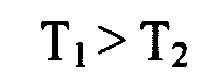

- The liquid crystal composition according to claim 2 or 3, which comprises a compound 1 having the clearing point T1 and a compound 2 having the clearing point T2, and which has the clearing point Tx, wherein the liquid crystal composition comprises 5 to 70 wt% of compound 1 and 30 to 95 wt% of compound 2, and wherein the clearing point T1, the clearing point T2 and the clearing point Tx of the liquid crystal composition satisfy the following conditions:


- The liquid crystal composition according to claim 2 or 3, which comprises a compound 1 having the clearing point T1 and a compound 2 having the clearing point T2, and which has the clearing point Tx, wherein the liquid crystal composition comprises 5 to 70 wt% of compound 1 and 30 to 95 wt% of compound 2, and wherein the clearing point T1, the clearing point T2 and the clearing point Tx of the liquid crystal composition satisfy the following conditions:

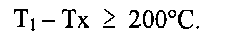
- The liquid crystal composition according to claim 2 or 3, which comprises a compound 1 having the clearing point T1 and a compound 2 having the clearing point T2, and which has the clearing point Tx, wherein the liquid crystal composition comprises 10 to 80 wt% of compound 1 and 20 to 90 wt% of compound 2, and wherein the clearing point T1, the clearing point T2 and the clearing point Tx of the liquid crystal composition satisfy the following conditions:


and wherein the liquid crystal composition is obtained by further adding chiral dopants to a composition in which the difference between the upper limit and the lower limit of a temperature allowing coexistence of a chiral nematic phase and a non-liquid crystalline isotropic phase is 3°C to 150°C. - The liquid crystal composition according to claim 2 or 3, which comprises a compound 1 having the clearing point T1 and a compound 2 having the clearing point T2, and which has the clearing point Tx, wherein the liquid crystal composition comprises 5 to 70 wt% of compound 1 and 30 to 95 wt% of compound 2, and wherein the clearing point T1, the clearing point T2 and the clearing point Tx of the liquid crystal composition satisfy the following conditions:


and wherein the liquid crystal composition is obtained by further adding chiral dopants to a composition in which the difference between the upper limit and the lower limit of a temperature allowing coexistence of a chiral nematic phase and a non-liquid crystalline isotropic phase is 3°C to 150°C. - The liquid crystal composition according to claim 7, wherein the liquid crystal composition comprises 30 to 60 wt% of compound 1 and 30 to 70 wt% of compound 2.
- The liquid crystal composition according to any one of claims 4 to 9, wherein the compound 1 is represented by the following general formula (1):
 Ra is hydrogen or alkyl having 1 to 20 carbon atoms, wherein any -CH2- in the alkyl can be replaced by -O-, -S-, -COO-, -OCO-, -CH=CH-, -CF=CF- or -C≡C-, and any hydrogen in the alkyl group can be replaced by halogen;Rb is hydrogen, halogen, -CN, -N=C=O, -N=C=S, -CF3, -OCF3 or alkyl having 1 to 20 carbon atoms, wherein any -CH2- in the alkyl can be replaced by -O-, -S-, -COO-, -OCO-, -CH=CH-, -CF=CF- or -C=C-, and any hydrogen in the alkyl can be replaced by halogen, and -CH3 in the alkyl can be replaced by -CN;A1 to A5 are each independently an aromatic or nonaromatic 3- to 8-membered ring or a condensed ring having 9 or more carbon atoms, wherein: any hydrogen in these rings can be replaced by halogen, alkyl having 1 to 3 carbon atoms or alkyl halide having 1 to 3 carbon atoms; any -CH2- in the rings can be replaced by -O-, -S-, or -NH-; any -CH= in the rings can be replaced by -N=; and A1 to A5 are not tetrahydropyran rings;Z1 to Z4 are each independently a single bond or alkylene having 1 to 8 carbon atoms, wherein any -CH2- in the alkylene can be replaced by -O-, -S-, -COO-, -OCO-, -CSO-, -OCS-, -N=N-, -CH=N-, -N=CH-, -N(O)=N-, -N=N(O)-, -CH=CH-, -CF=CF-or -C=C-, and any hydrogen can be replaced by halogen; andn1 to n3 are each independently 0 or 1; when Rb is hydrogen or fluorine, n2 and n3 are 1; when Z4 is -COO-, n2 and n3 are 1; and only when at least one of A4 and A5 is a condensed ring having 9 or more carbon atoms, all of n1 to n3 can be 0,and wherein the clearing point of the compound is 150°C to 400°C.
 - The liquid crystal composition according to claim 10, wherein:Ra is alkyl having 1 to 10 carbon atoms, wherein any -CH2- in the alkyl can be replaced by -O-, -S-, -COO-, -OCO-, -CH=CH- or -C≡C-;Rb is halogen, -CN, -N=C=O, -N=C=S, -CF3, -OCF3 or alkyl having 1 to 20 carbon atoms, wherein any -CH2- in the alkyl can be replaced by -O-, -CH=CH- or -C≡C-, and any hydrogen in the alkyl can be replaced by halogen, and -CH3 in the alkyl can be replaced by -CN;A1 to A5 are each independently a benzene ring, a naphthalene ring or a cyclohexane ring, wherein any hydrogen in these rings can be replaced by halogen, alkyl having 1 to 3 carbon atoms or alkyl halide having 1 to 3 carbon atoms, and any -CH2- in the rings can be replaced by -O- or -S-, and any -CH= in the rings can be replaced by -N=;Z1 to Z4 are each independently a single bond or alkylene having 1 to 4 carbon atoms, wherein any -CH2- in the alkylene can be replaced by -O-, -S-, -COO-, -OCO-, -CSO-, -OCS-, -CH=CH-, -CF=CF- or -C≡C-, and any hydrogen can be replaced by halogen; andn1 to n3 are each independently 0 or 1; when Rb is hydrogen or fluorine, n2 and n3 are 1; and only when at least one of A4 and A5 is a condensed ring having 9 or more carbon atoms, all of n1 to n3 can be 0.
- The liquid crystal composition according to claim 10, wherein:Ra is alkyl having 1 to 10 carbon atoms, wherein any -CH2- in the alkyl can be replaced by -CH=CH- or -C≡C-;Rb is fluorine, chlorine, -CN, -N=C=S or alkyl having 1 to 20 carbon atoms, wherein any -CH2- in the alkyl can be replaced by -O-, -CH=CH- or -C=C-;A1 to A5 are each independently a benzene ring, a naphthalene ring or a cyclohexane ring, wherein any hydrogen in the rings can be replaced by fluorine, chlorine, methyl, or methyl halide, and any -CH2- in the rings can be replaced by -O- or -S-, and any -CH= in the rings can be replaced by -N=;Z1 to Z4 are each independently a single bond or -C≡C-; andn1 to n3 are each independently 0 or 1; when Rb is hydrogen or fluorine, n2 and n3 are 1; and only when at least one of A4 and A5 is a condensed ring having 9 or more carbon atoms, all of n1 to n3 can be 0.
- The liquid crystal composition according to claim 10, wherein:Ra is alkyl having 1 to 10 carbon atoms, wherein any -CH2- in the alkyl can be replaced by -O- or -CH=CH-;Rb is fluorine, chlorine, -CN or alkyl having 1 to 10 carbon atoms, wherein any -CH2- in the alkyl can be replaced by -O-;A1 to A5 are each independently a benzene ring, a dioxane ring or a cyclohexane ring, wherein any hydrogen in the benzene ring can be replaced by fluorine;Z1 to Z4 are each independently a single bond or -C≡C-; andn1 is 1, and n2 and n3 are 0.
- The liquid crystal composition according to any one of claims 10 to 13, wherein the compound 2 is represented by the following general formula (2):
 Rc is hydrogen or alkyl having 1 to 20 carbon atoms, wherein any -CH2- in the alkyl can be replaced by -O-, -S-, -COO-, -OCO-, -CH=CH-, -CF=CF- or -C=C-, and any hydrogen in the alkyl can be replaced by halogen;Rd is halogen, -CN, -N=C=O, -N=C=S, -CF3, -OCF3, -C≡C-CN, or -C≡C-CF3;A6 and A7 are each independently an aromatic or nonaromatic 3- to 8-membered ring or a condensed ring having 9 or more carbon atoms, wherein any hydrogen in the rings can be replaced by halogen, alkyl having 1 to 3 carbon atoms or alkyl halide having 1 to 3 carbon atoms; any -CH2- in the rings can be replaced by -O-, -S-, or -NH-; and any -CH= in the rings can be replaced by -N=;Z6 is a single bond or alkylene having 1 to 8 carbon atoms, wherein any -CH2-in the alkylene can be replaced by -O-, -S-, -COO-, -OCO-, -CSO-, -OCS-, -N=N-, -CH=N-, -N=CH-, -N(O)=N-, -N=N(O)-, -CH=CH-, -CF=CF- or -C≡C-, and any hydrogen in the alkylene can be replaced by halogen; andn6 is 0 or 1; and when A7 is a condensed ring having 9 or more carbon atoms, n6 is 0.
 - The liquid crystal composition according to any one of claims 10 to 13, wherein:Rc is alkyl having 1 to 10 carbon atoms, wherein any -CH2- in the alkyl can be replaced by -O-, -S-, -COO-, -OCO-, -CH=CH- or -C≡C-;Rd is halogen, -CN, -N=C=S, -CF3, -C=C-CN or -C≡C-CF3;A6 and A7 are each independently a benzene ring, a naphthalene ring or a cyclohexane ring, wherein any hydrogen in these rings can be replaced by halogen, alkyl having 1 to 3 carbon atoms, or alkyl halide having 1 to 3 carbon atoms; any -CH2-in the rings can be replaced by -O- or -S-; and any -CH= in the rings can be replaced by -N=;Z6 is a single bond or alkylene having 1 to 4 carbon atoms, wherein any -CH2-in the alkylene can be replaced by -O-, -S-, -COO-, -OCO-, -CSO-, -OCS-, -CH=CH-,-CF=CF- or -C=C-; and any hydrogen in the alkylene can be replaced by halogen; and n6 is 0 or 1; and when A7 is a naphthalene ring, n6 is 0.
- The liquid crystal composition according to any one of claims 10 to 13, wherein:Rc is alkyl having 1 to 10 carbon atoms, wherein any -CH2- in the alkyl can be replaced by -CH=CH- or -C≡C-;Rd is halogen, -CN, -N=C=S, -CF3, -C≡C-CN or -C≡C-CF3;A6 and A7 are each independently a benzene ring, a naphthalene ring or a cyclohexane ring, wherein any hydrogen in these rings can be replaced by fluorine, chlorine, methyl or methyl halide; any -CH2- in these rings can be replaced by -O- or -S-; and any -CH= in the rings can be replaced by -N=;Z6 is a single bond, -COO-, -CF2O- or -C≡C-; andn6 is 0 or 1; and when A7 is a naphthalene ring, n6 is 0.
- The liquid crystal composition according to any one of claims 10 to 13, wherein:Rc is alkyl having 1 to 10 carbon atoms, wherein any -CH2- in the alkyl can be replaced by -O-;Rd is halogen or -CN;A6 and A7 are each independently a benzene ring, a dioxane ring or a cyclohexane ring, wherein any hydrogen in the benzene ring can be replaced by fluorine;Z6 is a single bond or -COO-; andn6 is 0 or 1.
- The liquid crystal composition according to any one of claims 10 to 13, wherein the compound 2 is represented by the following general formula (3):
 Re is alkyl having 1 to 10 carbon atoms, wherein any -CH2- in the alkyl can be replaced by -O-, -S-, -COO-, -OCO-, -CH=CH-, -CF=CF- or -C≡C-; and any hydrogen in the alkyl can be replaced by halogen;Xa is fluorine, chlorine, -CN, -N=C=S, -CF3, -C≡C-CN or -C≡C-CF3;Z12 is a single bond, -COO- or -C≡C-; andL8 to L11 are each independently hydrogen or fluorine.
 - The liquid crystal composition according to any one of claims 10 to 13, wherein:Re is alkyl having 1 to 10 carbon atoms, wherein any -CH2- in the alkyl can be replaced by -O-, -CH=CH- or -C≡C-;Xa is fluorine or -CN;Z12 is -COO-; andL8 to L11are each independently hydrogen or fluorine, wherein at least two of them are fluorine.
- The liquid crystal composition according to claim 2 or 3, which is obtained by further adding chiral dopants to a composition in which the difference between the upper limit and the lower limit of a temperature allowing coexistence of a chiral nematic phase and a non-liquid crystalline isotropic phase is 3°C to 150°C.
- The liquid crystal composition according to claim 2 or 3, which is obtained by further adding chiral dopants to a composition in which the difference between the upper limit and the lower limit of a temperature allowing coexistence of a chiral nematic phase and a non-liquid crystalline isotropic phase is 5°C to 150°C.
- The liquid crystal composition according to claim 2 or 3, which is obtained by further adding chiral dopants to a composition in which the difference between the upper limit and the lower limit of a temperature allowing coexistence of a nematic phase and a non-liquid crystalline isotropic phase is 3°C to 150°C.
- The liquid crystal composition according to any one of claims 1 to 22, wherein the chiral dopants are included in an amount of 1 to 40 wt% per the total weight of the liquid crystal composition.
- The liquid crystal composition according to any one of claims 1 to 22, wherein the chiral dopants are included in an amount of 5 to 15 wt% per the total weight of the liquid crystal composition.
- The liquid crystal composition according to claim 23 or 24, wherein the pitch is 700 nm or lower.
- The liquid crystal composition according to any one of claims 23 to 25, wherein the chiral dopants comprise one or more compounds represented by any one of the following formulae (K1) to (K5):
 each RK is independently hydrogen, halogen, -CN, -N=C=O, -N=C=S or alkyl having 1 to 20 carbon atoms, wherein any -CH2- in the alkyl can be replaced by -O-, -S-, -COO-, -OCO-, -CH=CH-, -CF=CF- or -C≡C-; and any hydrogen in the alkyl can be replaced by halogen;each A is independently an aromatic or nonaromatic 3- to 8-membered ring or a condensed ring having 9 or more carbon atoms, wherein any hydrogen in these rings can be replaced by halogen, alkyl having 1 to 3 carbon atoms or haloalkyl having 1 to 3 carbon atoms; any -CH2- in the rings can be replaced by -O-, -S- or -NH-; and any -CH= in the rings can be replaced by -N=;each Z is independently a single bond or alkylene having 1 to 8 carbon atoms, wherein any -CH2- can be replaced by -O-, -S-, -COO-, -OCO-, -CSO-, -OCS-, -N=N-, -CH=N-, -N=CH-, -N(O)=N-, -N=N(O)-, -CH=CH-, -CF=CF- or -C≡C-; and any hydrogen can be replaced by halogen;X is a single bond, -COO-, -CH2O, -CF2O-or -CH2CH2-; andm is 1 to 4.
 - The liquid crystal composition according to any one of claims 23 to 25, wherein the chiral dopants comprise one or more compounds represented by any one of the following formulae (K2-1) to (K2-8) and (K5-1) to (K5-3):


 each RK is independently alkyl having 3 to 10 carbon atoms, wherein -CH2-adjacent to the ring in the alkyl can be replaced by -O-; and any -CH2- in the alkyl can be replaced by -CH=CH-.
 - A liquid crystal composition, which comprises a compound 1 having the clearing point T1, a compound 2 having the clearing point T2 and chiral dopants, and whose clearing point is Tx,
wherein:the liquid crystal composition comprises 20 to 40 wt% of compound 1, 20 to 60 wt% of compound 2, and 5 to 20 wt% of chiral dopants;the compound 1 is represented by the following general formula (1): Ra and Rb are each independently alkyl having 1 to 10 carbon atoms, wherein any -CH2- in the alkyl can be replaced by -O-;A1 to A4 are each independently a benzene ring, a dioxane ring or a cyclohexane ring, wherein any hydrogen in these rings can be replaced by fluorine, and A5 is a benzene ring;Z1 to Z4 are each independently a single bond or -C≡C-; andn1 is 1, and n2 and n3 are 0;the compound 2 consists of a compound represented by the following general formula (2) and a compound represented by the following general formula (3),
 wherein in the formula (2):Rc is alkyl having 1 to 10 carbon atoms, wherein any -CH2- in the alkyl can be replaced by -O-;Rd is halogen or -CN;A6 is a benzene ring or a cyclohexane ring, wherein any hydrogen in these rings can be replaced by fluorine, and A7 is a benzene ring;Z6 is a single bond or -COO-; andn6 is 1,
 and wherein in the formula (3):Re is alkyl having 1 to 10 carbon atoms, wherein any -CH2- in the alkyl can be replaced by -O-, -CH=CH- or -C≡C-;Xa is fluorine or -CN;Z12 is -COO-; andL8 to L11 are each independently hydrogen or fluorine, wherein at least two of them are fluorine, and at least one of L10 and L11 is fluorine,and wherein the chiral dopants comprise one or more compounds represented by the following formulae (K2-5) to (K2-8):


 wherein each RK is independently alkyl having 3 to 10 carbon atoms, wherein -CH2- adjacent to the ring in the alkyl can be replaced by -O-, and any -CH2- in the alkyl can be replaced by -CH=CH-;the clearing point T1, the clearing point T2 and the clearing point Tx of the liquid crystal composition satisfy the following conditions:

andan optically isotropic liquid crystal phase has an optically isotropic phase which does not show diffracted light with two or more colors. - A liquid crystal composition, which comprises a compound 1 having the clearing point T1, a compound 2 having the clearing point T2 and chiral dopants, and whose clearing point is Tx,
wherein:the liquid crystal composition comprises 8 to 30 wt% of compound 1, 40 to 60 wt% of compound 2, and 5 to 20 wt% of chiral dopants;the compound 1 is represented by the following general formula (1): wherein:Ra is alkyl having 1 to 10 carbon atoms, wherein any -CH2- in the alkyl can be replaced by -O-;A1 to A4 are each independently a benzene ring, a dioxane ring or a cyclohexane ring, wherein any hydrogen in the benzene ring can be replaced by fluorine, and A5 is a benzene ring;Z1 to Z4 are each independently a single bond or -C≡C-; andn1 and n2 are 1 and n3 is 0;the compound 2 is represented by the following general formula (3):
 wherein:Re is alkyl having 1 to 10 carbon atoms, wherein any -CH2- in the alkyl can be replaced by -O-, -CH=CH- or -C≡C-;Xa is fluorine or -CN;Z12 is -COO-; andL8 to L11 are each independently hydrogen or fluorine, wherein at least two of them are fluorine, and at least one of L10 and L11 is fluorine;the chiral dopants comprise one or more compounds represented by the following formulae (K2-5) to (K2-8):


 wherein each RK is independently alkyl having 3 to 10 carbon atoms, wherein -CH2- adjacent to the ring in the alkyl can be replaced by -O-, and any -CH2- in the alkyl can be replaced by -CH=CH-;the clearing point T1, the clearing point T2 and the clearing point Tx of the liquid crystal composition satisfy the following conditions:

andan optically isotropic liquid crystal phase has an optically isotropic phase which shows diffracted light with two or more colors. - A liquid crystal composition, which comprises a compound 1 having the clearing point T1, a compound 2 having the clearing point T2 and chiral dopants, and whose clearing point is Tx,
wherein:the liquid crystal composition comprises 20 to 40 wt% of compound 1, 20 to 60 wt% of compound 2, and 5 to 25 wt% of chiral dopants;the compound 1 is represented by the following general formula (1): wherein:Ra is alkyl having 1 to 10 carbon atoms, wherein any -CH2- in the alkyl can be replaced by -O-;Rb is halogen, -CN, -N=C=O, -N=C=S, -CF3, or -OCF3;A1 to A4 are each independently a benzene ring, a dioxane ring or a cyclohexane ring, wherein any hydrogen in the benzene ring can be replaced by fluorine, and A5 is a benzene ring;Z1 to Z4 are each independently a single bond or -C=C-; andn1 is 1, and n2 and n3 are 0;the compound 2 consists of a compound represented by the following general formula (2) and a compound represented by the following general formula (3),
 wherein in the formula (2):Rc is alkyl having 1 to 10 carbon atoms, wherein any -CH2- in the alkyl can be replaced by -O-;Rd is halogen or -CN;A6 is a benzene ring or a cyclohexane ring, wherein any hydrogen in these rings can be replaced by fluorine, and A7 is a benzene ring;Z6 is a single bond or -COO-; andn6 is 1,
 and wherein in the formula (3):Re is alkyl having 1 to 10 carbon atoms, wherein any -CH2- in the alkyl can be replaced by -O-, -CH=CH- or -C≡C-;Xa is fluorine or -CN;Z12 is -COO-; andL8 to L11 are each independently hydrogen or fluorine, wherein at least two of them are fluorine, and at least one of L10 and L11 is fluorine,and wherein the chiral dopants comprise one or more compounds represented by the following formulae (K2-5) to (K2-8):


 wherein each RK is independently alkyl having 3 to 10 carbon atoms, wherein -CH2- adjacent to the ring in the alkyl can be replaced by -O-, and any -CH2- in the alkyl can be replaced by -CH=CH-;the clearing point T1, the clearing point T2 and the clearing point Tx of the liquid crystal composition satisfy the following conditions:

andan optically isotropic liquid crystal phase has an optically isotropic phase which does not show diffracted light with two or more colors. - A liquid crystal element, in which an electrode is placed on one or both surfaces thereof, and which has a liquid crystal composition placed between substrates and an electric field applying means for applying electric field on the liquid crystal composition via the electrode, wherein the liquid crystal composition is that according to any one of claims 1 to 30.
- A liquid crystal element, in which an electrode is placed on one or both surfaces thereof, and which has: a pair of substrates, at least one of which is transparent; a liquid crystal composition placed between the substrates; and polarization plates placed on the external sides of the substrates, and which has an electric field applying means for applying electric field on the liquid crystal composition via the electrode, wherein the liquid crystal composition is that according to any one of claims 1 to 30.
- The liquid crystal element according to claim 32, wherein the electrode is constituted on at least one of the pair of substrates so that electric field can be applied in at least two directions.
- The liquid crystal element according to claim 32, wherein the electrode is constituted on one or both of the pair of substrates placed in parallel with each other so that electric field can be applied in at least two directions.
- The liquid crystal element according to any one of claims 31 to 34, wherein: the electrode is placed in a matrix state to constitute a pixel electrode; each pixel has an active element; and the active element is a thin film transistor (TFT).
- A liquid crystal composition, which comprises a compound 1 having the clearing point T1 and a compound 2 having the clearing point T2, and whose clearing point is Tx, the liquid crystal composition being used in an element driven in a state of an optically isotropic liquid crystal phase,
wherein:the liquid crystal composition comprises 10 to 80 wt% of compound 1 and 20 to 90 wt% of compound 2; andthe clearing point T1, the clearing point T2 and the clearing point Tx of the liquid crystal composition satisfy the following conditions:

- A liquid crystal composition, which is a component of a liquid crystal composition used in an element driven in a state of an optically isotropic liquid crystal phase, wherein the difference between the upper limit and the lower limit of a temperature allowing coexistence of a chiral nematic phase and a non-liquid crystalline isotropic phase is 3°C to 150°C.
- The liquid crystal composition according to claim 36, wherein the difference between the upper limit and the lower limit of a temperature allowing coexistence of a chiral nematic phase and a non-liquid crystalline isotropic phase is 3°C to 150°C.
- The liquid crystal composition according to claim 36 or 38,
wherein:the compound 1 is represented by the following general formula (1): wherein:Ra is hydrogen or alkyl having 1 to 20 carbon atoms, wherein any -CH2- in the alkyl can be replaced by -O-, -S-, -COO-, -OCO-, -CH=CH-, -CF=CF-, or -C≡C-, and any hydrogen in the alkyl group can be replaced by halogen;Rb is hydrogen, halogen, -CN, -N=C=O, -N=C=S, -CF3, -OCF3, or alkyl having 1 to 20 carbon atoms, wherein: any -CH2- in the alkyl can be replaced by -O-, -S-, -COO-, -OCO-, -CH=CH-, -CF=CF-, or -C≡C-; any hydrogen in the alkyl can be replaced by halogen; and -CH3 in the alkyl can be replaced by -CN;A1 to A5 are each independently an aromatic or nonaromatic 3- to 8-membered ring or a condensed ring having 9 or more carbon atoms, wherein: any hydrogen in these rings can be replaced by halogen, alkyl having 1 to 3 carbon atoms or alkyl halide having 1 to 3 carbon atoms; any -CH2- in the rings can be replaced by -O-, -S-, or -NH-; any -CH= in the rings can be replaced by -N=; and A1 to A5 are not tetrahydropyran rings;Z1 to Z4 are each independently a single bond or alkylene having 1 to 8 carbon atoms, wherein any -CH2- in the alkylene can be replaced by -O-, -S-, -COO-, -OCO-, -CSO-, -OCS-, -N=N-, -CH=N-, -N=CH-, -N(O)=N-, -N=N(O)-, -CH=CH-, -CF=CF- or -C≡C-, and any hydrogen can be replaced by halogen; andn1 to n3 are each independently 0 or 1; when Rb is hydrogen or fluorine, n2 and n3 are 1; when Z4 is -COO-, n2 and n3 are 1; and only when at least one of A4 and A5 is a condensed ring having 9 or more carbon atoms, all of n1 to n3 can be 0; andthe clearing point of the compound is 150°C to 400°C.
 - The liquid crystal composition according to claim 36, 38 or 39, wherein the compound 2 is represented by the following general formula (2):
 Rc is hydrogen or alkyl having 1 to 20 carbon atoms, wherein any -CH2- in the alkyl can be replaced by -O-, -S-, -COO-, -OCO-, -CH=CH-, -CF=CF- or -C≡C-, and any hydrogen in the alkyl can be replaced by halogen;Rd is halogen, -CN, -N=C=O, -N=C=S, -CF3, -OCF3, -C≡C-CN, or -C≡C-CF3;A6 and A7 are each independently an aromatic or nonaromatic 3- to 8-membered ring or a condensed ring having 9 or more carbon atoms, wherein any hydrogen in the rings can be replaced by halogen, alkyl having 1 to 3 carbon atoms or alkyl halide having 1 to 3 carbon atoms; any -CH2- in the rings can be replaced by -O-, -S-, or -NH-; and any -CH= in the rings can be replaced by -N=;Z6 is a single bond or alkylene having 1 to 8 carbon atoms, wherein any -CH2-in the alkylene can be replaced by -O-, -S-, -COO-, -OCO-, -CSO-, -OCS-, -N=N-, -CH=N-, -N=CH-, -N(O)=N-, -N=N(O)-, -CH=CH-, -CF=CF- or -C≡C-, and any hydrogen in the alkylene can be replaced by halogen; andn6 is 0 or 1; and when A7 is a condensed ring having 9 or more carbon atoms, n6 is 0.
 - The liquid crystal composition according to any one of claims 36 and 38 to 40, wherein the compound 2 is represented by the following general formula (3):
 Re is alkyl having 1 to 10 carbon atoms, wherein any -CH2- in the alkyl can be replaced by -O-, -S-, -COO-, -OCO-, -CH=CH-, -CF=CF- or -C≡C-, and any hydrogen in the alkyl can be replaced by halogen;Xa is fluorine, chlorine, -CN, -N=C=S, -CF3, -C≡C-CN or -C≡C-CF3;Z12 is a single bond, -COO- or -C≡C-; andL8 to L11 are each independently hydrogen or fluorine.
Priority Applications (1)
| Application Number | Priority Date | Filing Date | Title |
|---|---|---|---|
| EP13192639.6A EP2698415B1 (en) | 2006-03-13 | 2007-03-09 | Liquid-crystal composition and liquid-crystal element |
Applications Claiming Priority (2)
| Application Number | Priority Date | Filing Date | Title |
|---|---|---|---|
| JP2006067521 | 2006-03-13 | ||
| PCT/JP2007/055300 WO2007105803A1 (en) | 2006-03-13 | 2007-03-09 | Liquid-crystal composition and liquid-crystal element |
Related Child Applications (1)
| Application Number | Title | Priority Date | Filing Date |
|---|---|---|---|
| EP13192639.6A Division EP2698415B1 (en) | 2006-03-13 | 2007-03-09 | Liquid-crystal composition and liquid-crystal element |
Publications (3)
| Publication Number | Publication Date |
|---|---|
| EP2006352A1 true EP2006352A1 (en) | 2008-12-24 |
| EP2006352A4 EP2006352A4 (en) | 2012-11-28 |
| EP2006352B1 EP2006352B1 (en) | 2013-12-11 |
Family
ID=38509616
Family Applications (2)
| Application Number | Title | Priority Date | Filing Date |
|---|---|---|---|
| EP13192639.6A Not-in-force EP2698415B1 (en) | 2006-03-13 | 2007-03-09 | Liquid-crystal composition and liquid-crystal element |
| EP07738747.0A Not-in-force EP2006352B1 (en) | 2006-03-13 | 2007-03-09 | Liquid-crystal composition and liquid-crystal element |
Family Applications Before (1)
| Application Number | Title | Priority Date | Filing Date |
|---|---|---|---|
| EP13192639.6A Not-in-force EP2698415B1 (en) | 2006-03-13 | 2007-03-09 | Liquid-crystal composition and liquid-crystal element |
Country Status (5)
| Country | Link |
|---|---|
| US (1) | US8349209B2 (en) |
| EP (2) | EP2698415B1 (en) |
| KR (1) | KR101436877B1 (en) |
| CN (1) | CN101400761B (en) |
| WO (1) | WO2007105803A1 (en) |
Cited By (1)
| Publication number | Priority date | Publication date | Assignee | Title |
|---|---|---|---|---|
| EP3599266A1 (en) * | 2018-07-24 | 2020-01-29 | Merck Patent GmbH | Liquid-crystal lens |
Families Citing this family (8)
| Publication number | Priority date | Publication date | Assignee | Title |
|---|---|---|---|---|
| JP5577566B2 (en) * | 2007-08-31 | 2014-08-27 | Jnc株式会社 | Liquid crystal composition and liquid crystal element |
| CN102216424B (en) * | 2008-11-19 | 2014-05-07 | Jnc株式会社 | Optically isotropic liquid crystal medium and optical element |
| KR101898048B1 (en) * | 2009-08-28 | 2018-09-12 | 고쿠리쓰다이가쿠호진 규슈다이가쿠 | Liquid-crystal display element and substrate used in same |
| CN102947262B (en) * | 2010-06-22 | 2016-04-13 | 捷恩智株式会社 | Compounds with branched alkyl or branched alkenyl groups and optically isotropic liquid crystal media and optical components |
| DE102011119900A1 (en) * | 2011-01-21 | 2012-07-26 | Merck Patent Gmbh | Liquid-crystalline media, components for high frequency technology and mesogenic compounds |
| US10056557B2 (en) * | 2011-03-10 | 2018-08-21 | Tokyo Institute Of Technology | Organic semiconductor material |
| JP5948832B2 (en) * | 2011-12-08 | 2016-07-06 | Jnc株式会社 | Optically isotropic liquid crystal composition and optical device containing monofunctional monofunctional monomer |
| JP6942457B2 (en) | 2016-10-25 | 2021-09-29 | Jnc株式会社 | Liquid crystal media, optical devices and liquid crystal compounds |
Family Cites Families (11)
| Publication number | Priority date | Publication date | Assignee | Title |
|---|---|---|---|---|
| JP3494225B2 (en) * | 1992-07-28 | 2004-02-09 | チッソ株式会社 | Tolan derivative, liquid crystal composition containing the same, and liquid crystal display device using the same |
| US5858271A (en) * | 1996-02-09 | 1999-01-12 | Chisso Corporation | Liquid crystal composition and liquid crystal display device |
| WO1998000428A1 (en) | 1996-07-01 | 1998-01-08 | Merck Patent Gmbh | Chiral dopants |
| DE10047091A1 (en) | 2000-09-21 | 2002-04-11 | Merck Patent Gmbh | Liquid crystalline mixtures |
| JP2002363564A (en) * | 2001-06-01 | 2002-12-18 | Minolta Co Ltd | Liquid crystal composition and reflective liquid crystal display device |
| JP3779937B2 (en) | 2002-05-08 | 2006-05-31 | 独立行政法人科学技術振興機構 | Liquid crystal material for optical modulator |
| JP2004018581A (en) * | 2002-06-13 | 2004-01-22 | Chisso Corp | Polymer / liquid crystal composite material and optical device using the same |
| JP2004182881A (en) * | 2002-12-04 | 2004-07-02 | Chisso Corp | Liquid crystal composition and liquid crystal display device |
| US7576829B2 (en) * | 2004-03-19 | 2009-08-18 | Japan Science And Technology Agency | Liquid crystal display device |
| JP5269284B2 (en) * | 2004-04-30 | 2013-08-21 | 独立行政法人科学技術振興機構 | Composite material comprising polymer and liquid crystal material having chirality, method for producing the composite material, and optical element using the composite material |
| US7648647B2 (en) * | 2007-05-08 | 2010-01-19 | Kyushu University, National University Corporation | Polymer/liquid crystal composite and liquid crystal element |
-
2007
- 2007-03-09 US US12/282,872 patent/US8349209B2/en not_active Expired - Fee Related
- 2007-03-09 EP EP13192639.6A patent/EP2698415B1/en not_active Not-in-force
- 2007-03-09 WO PCT/JP2007/055300 patent/WO2007105803A1/en not_active Ceased
- 2007-03-09 CN CN200780008868.4A patent/CN101400761B/en not_active Expired - Fee Related
- 2007-03-09 EP EP07738747.0A patent/EP2006352B1/en not_active Not-in-force
- 2007-03-09 KR KR1020087024719A patent/KR101436877B1/en not_active Expired - Fee Related
Cited By (2)
| Publication number | Priority date | Publication date | Assignee | Title |
|---|---|---|---|---|
| EP3599266A1 (en) * | 2018-07-24 | 2020-01-29 | Merck Patent GmbH | Liquid-crystal lens |
| US11473014B2 (en) * | 2018-07-24 | 2022-10-18 | Merck Patent Gmbh | Liquid-crystal lens |
Also Published As
| Publication number | Publication date |
|---|---|
| KR101436877B1 (en) | 2014-09-02 |
| US8349209B2 (en) | 2013-01-08 |
| EP2698415B1 (en) | 2016-03-09 |
| EP2006352B1 (en) | 2013-12-11 |
| US20090323010A1 (en) | 2009-12-31 |
| EP2698415A3 (en) | 2014-06-11 |
| CN101400761A (en) | 2009-04-01 |
| WO2007105803A1 (en) | 2007-09-20 |
| CN101400761B (en) | 2016-03-09 |
| EP2698415A2 (en) | 2014-02-19 |
| EP2006352A4 (en) | 2012-11-28 |
| KR20080104189A (en) | 2008-12-01 |
Similar Documents
| Publication | Publication Date | Title |
|---|---|---|
| EP2698415B1 (en) | Liquid-crystal composition and liquid-crystal element | |
| JP7844101B2 (en) | liquid crystal medium | |
| JP4027939B2 (en) | Display element and display device | |
| GB2387603A (en) | Liquid crystalline medium and liquid crystal display | |
| JP5871445B2 (en) | Liquid crystal composition and liquid crystal element | |
| JP2014513150A (en) | Liquid crystal display with homeotropic alignment | |
| US9085730B2 (en) | Liquid crystal composition and device thereof | |
| JP5036958B2 (en) | Liquid crystal medium | |
| JP2018537706A (en) | Light modulation element | |
| JPH0675224A (en) | Twisted spiral effect type electro-optical element and ferroelectric liquid crystal composition used therefor | |
| TW201615805A (en) | Mesogenic media and liquid crystal display | |
| TW202212542A (en) | Liquid crystal medium | |
| TW202206577A (en) | Liquid crystal medium | |
| US7041348B2 (en) | Liquid crystalline medium and liquid crystal display | |
| KR20230156887A (en) | Liquid-crystal medium | |
| CN105874035A (en) | Light modulation element | |
| CN114196420B (en) | Liquid crystal composition and liquid crystal display device thereof | |
| JP2011500917A (en) | Oligosiloxane-modified liquid crystal compound and device using the same | |
| CN110997870B (en) | Liquid crystal medium and liquid crystal device | |
| JP5575349B2 (en) | Liquid crystal medium and electro-optic liquid crystal display | |
| JP2007529767A (en) | Electro-optic light modulator, display and medium | |
| JP2023541355A (en) | Liquid crystal composition and liquid crystal display device thereof | |
| TWI800577B (en) | Liquid crystal compound and liquid crystal medium | |
| CN111263799A (en) | Liquid crystal medium and liquid crystal device | |
| EP4558582A1 (en) | Liquid crystalline medium |
Legal Events
| Date | Code | Title | Description |
|---|---|---|---|
| PUAI | Public reference made under article 153(3) epc to a published international application that has entered the european phase |
Free format text: ORIGINAL CODE: 0009012 |
|
| 17P | Request for examination filed |
Effective date: 20081008 |
|
| AK | Designated contracting states |
Kind code of ref document: A1 Designated state(s): AT BE BG CH CY CZ DE DK EE ES FI FR GB GR HU IE IS IT LI LT LU LV MC MT NL PL PT RO SE SI SK TR |
|
| RAP1 | Party data changed (applicant data changed or rights of an application transferred) |
Owner name: KYUSHU UNIVERSITY, NATIONAL UNIVERSITY CORPORATION Owner name: JNC CORPORATION Owner name: CHISSO PETROCHEMICAL CORPORATION |
|
| RAP1 | Party data changed (applicant data changed or rights of an application transferred) |
Owner name: JNC CORPORATION Owner name: JNC PETROCHEMICAL CORPORATION Owner name: KYUSHU UNIVERSITY, NATIONAL UNIVERSITY CORPORATION |
|
| DAX | Request for extension of the european patent (deleted) | ||
| A4 | Supplementary search report drawn up and despatched |
Effective date: 20121026 |
|
| RIC1 | Information provided on ipc code assigned before grant |
Ipc: C09K 19/30 20060101ALI20121022BHEP Ipc: C09K 19/02 20060101ALI20121022BHEP Ipc: C09K 19/54 20060101ALI20121022BHEP Ipc: C09K 19/20 20060101ALI20121022BHEP Ipc: G02F 1/13 20060101ALI20121022BHEP Ipc: C09K 19/18 20060101ALI20121022BHEP Ipc: C09K 19/12 20060101ALI20121022BHEP Ipc: C09K 19/34 20060101ALI20121022BHEP Ipc: C09K 19/16 20060101ALI20121022BHEP Ipc: C09K 19/42 20060101AFI20121022BHEP |
|
| GRAP | Despatch of communication of intention to grant a patent |
Free format text: ORIGINAL CODE: EPIDOSNIGR1 |
|
| RIC1 | Information provided on ipc code assigned before grant |
Ipc: G02F 1/13 20060101ALI20130613BHEP Ipc: C09K 19/18 20060101ALI20130613BHEP Ipc: C09K 19/34 20060101ALI20130613BHEP Ipc: C09K 19/30 20060101ALI20130613BHEP Ipc: C09K 19/02 20060101ALI20130613BHEP Ipc: C09K 19/20 20060101ALI20130613BHEP Ipc: C09K 19/42 20060101AFI20130613BHEP Ipc: G02F 1/137 20060101ALI20130613BHEP Ipc: C09K 19/54 20060101ALI20130613BHEP Ipc: C09K 19/12 20060101ALI20130613BHEP Ipc: C09K 19/16 20060101ALI20130613BHEP |
|
| INTG | Intention to grant announced |
Effective date: 20130705 |
|
| GRAS | Grant fee paid |
Free format text: ORIGINAL CODE: EPIDOSNIGR3 |
|
| GRAA | (expected) grant |
Free format text: ORIGINAL CODE: 0009210 |
|
| AK | Designated contracting states |
Kind code of ref document: B1 Designated state(s): AT BE BG CH CY CZ DE DK EE ES FI FR GB GR HU IE IS IT LI LT LU LV MC MT NL PL PT RO SE SI SK TR |
|
| REG | Reference to a national code |
Ref country code: GB Ref legal event code: FG4D |
|
| REG | Reference to a national code |
Ref country code: CH Ref legal event code: EP |
|
| REG | Reference to a national code |
Ref country code: AT Ref legal event code: REF Ref document number: 644608 Country of ref document: AT Kind code of ref document: T Effective date: 20140115 |
|
| REG | Reference to a national code |
Ref country code: IE Ref legal event code: FG4D |
|
| REG | Reference to a national code |
Ref country code: DE Ref legal event code: R096 Ref document number: 602007034203 Country of ref document: DE Effective date: 20140206 |
|
| REG | Reference to a national code |
Ref country code: NL Ref legal event code: VDEP Effective date: 20131211 |
|
| REG | Reference to a national code |
Ref country code: AT Ref legal event code: MK05 Ref document number: 644608 Country of ref document: AT Kind code of ref document: T Effective date: 20131211 |
|
| PG25 | Lapsed in a contracting state [announced via postgrant information from national office to epo] |
Ref country code: NL Free format text: LAPSE BECAUSE OF FAILURE TO SUBMIT A TRANSLATION OF THE DESCRIPTION OR TO PAY THE FEE WITHIN THE PRESCRIBED TIME-LIMIT Effective date: 20131211 Ref country code: LT Free format text: LAPSE BECAUSE OF FAILURE TO SUBMIT A TRANSLATION OF THE DESCRIPTION OR TO PAY THE FEE WITHIN THE PRESCRIBED TIME-LIMIT Effective date: 20131211 Ref country code: SE Free format text: LAPSE BECAUSE OF FAILURE TO SUBMIT A TRANSLATION OF THE DESCRIPTION OR TO PAY THE FEE WITHIN THE PRESCRIBED TIME-LIMIT Effective date: 20131211 Ref country code: FI Free format text: LAPSE BECAUSE OF FAILURE TO SUBMIT A TRANSLATION OF THE DESCRIPTION OR TO PAY THE FEE WITHIN THE PRESCRIBED TIME-LIMIT Effective date: 20131211 |
|
| REG | Reference to a national code |
Ref country code: LT Ref legal event code: MG4D |
|
| PG25 | Lapsed in a contracting state [announced via postgrant information from national office to epo] |
Ref country code: AT Free format text: LAPSE BECAUSE OF FAILURE TO SUBMIT A TRANSLATION OF THE DESCRIPTION OR TO PAY THE FEE WITHIN THE PRESCRIBED TIME-LIMIT Effective date: 20131211 Ref country code: CY Free format text: LAPSE BECAUSE OF FAILURE TO SUBMIT A TRANSLATION OF THE DESCRIPTION OR TO PAY THE FEE WITHIN THE PRESCRIBED TIME-LIMIT Effective date: 20131211 Ref country code: LV Free format text: LAPSE BECAUSE OF FAILURE TO SUBMIT A TRANSLATION OF THE DESCRIPTION OR TO PAY THE FEE WITHIN THE PRESCRIBED TIME-LIMIT Effective date: 20131211 |
|
| PG25 | Lapsed in a contracting state [announced via postgrant information from national office to epo] |
Ref country code: BE Free format text: LAPSE BECAUSE OF FAILURE TO SUBMIT A TRANSLATION OF THE DESCRIPTION OR TO PAY THE FEE WITHIN THE PRESCRIBED TIME-LIMIT Effective date: 20131211 Ref country code: EE Free format text: LAPSE BECAUSE OF FAILURE TO SUBMIT A TRANSLATION OF THE DESCRIPTION OR TO PAY THE FEE WITHIN THE PRESCRIBED TIME-LIMIT Effective date: 20131211 Ref country code: IS Free format text: LAPSE BECAUSE OF FAILURE TO SUBMIT A TRANSLATION OF THE DESCRIPTION OR TO PAY THE FEE WITHIN THE PRESCRIBED TIME-LIMIT Effective date: 20140411 |
|
| PG25 | Lapsed in a contracting state [announced via postgrant information from national office to epo] |
Ref country code: PL Free format text: LAPSE BECAUSE OF FAILURE TO SUBMIT A TRANSLATION OF THE DESCRIPTION OR TO PAY THE FEE WITHIN THE PRESCRIBED TIME-LIMIT Effective date: 20131211 Ref country code: ES Free format text: LAPSE BECAUSE OF FAILURE TO SUBMIT A TRANSLATION OF THE DESCRIPTION OR TO PAY THE FEE WITHIN THE PRESCRIBED TIME-LIMIT Effective date: 20131211 Ref country code: SK Free format text: LAPSE BECAUSE OF FAILURE TO SUBMIT A TRANSLATION OF THE DESCRIPTION OR TO PAY THE FEE WITHIN THE PRESCRIBED TIME-LIMIT Effective date: 20131211 Ref country code: CZ Free format text: LAPSE BECAUSE OF FAILURE TO SUBMIT A TRANSLATION OF THE DESCRIPTION OR TO PAY THE FEE WITHIN THE PRESCRIBED TIME-LIMIT Effective date: 20131211 Ref country code: RO Free format text: LAPSE BECAUSE OF FAILURE TO SUBMIT A TRANSLATION OF THE DESCRIPTION OR TO PAY THE FEE WITHIN THE PRESCRIBED TIME-LIMIT Effective date: 20131211 Ref country code: PT Free format text: LAPSE BECAUSE OF FAILURE TO SUBMIT A TRANSLATION OF THE DESCRIPTION OR TO PAY THE FEE WITHIN THE PRESCRIBED TIME-LIMIT Effective date: 20140411 |
|
| REG | Reference to a national code |
Ref country code: DE Ref legal event code: R097 Ref document number: 602007034203 Country of ref document: DE |
|
| PLBE | No opposition filed within time limit |
Free format text: ORIGINAL CODE: 0009261 |
|
| STAA | Information on the status of an ep patent application or granted ep patent |
Free format text: STATUS: NO OPPOSITION FILED WITHIN TIME LIMIT |
|
| PG25 | Lapsed in a contracting state [announced via postgrant information from national office to epo] |
Ref country code: DK Free format text: LAPSE BECAUSE OF FAILURE TO SUBMIT A TRANSLATION OF THE DESCRIPTION OR TO PAY THE FEE WITHIN THE PRESCRIBED TIME-LIMIT Effective date: 20131211 Ref country code: LU Free format text: LAPSE BECAUSE OF FAILURE TO SUBMIT A TRANSLATION OF THE DESCRIPTION OR TO PAY THE FEE WITHIN THE PRESCRIBED TIME-LIMIT Effective date: 20140309 |
|
| REG | Reference to a national code |
Ref country code: CH Ref legal event code: PL |
|
| 26N | No opposition filed |
Effective date: 20140912 |
|
| GBPC | Gb: european patent ceased through non-payment of renewal fee |
Effective date: 20140311 |
|
| REG | Reference to a national code |
Ref country code: DE Ref legal event code: R097 Ref document number: 602007034203 Country of ref document: DE Effective date: 20140912 |
|
| REG | Reference to a national code |
Ref country code: FR Ref legal event code: ST Effective date: 20141128 |
|
| REG | Reference to a national code |
Ref country code: IE Ref legal event code: MM4A |
|
| PG25 | Lapsed in a contracting state [announced via postgrant information from national office to epo] |
Ref country code: CH Free format text: LAPSE BECAUSE OF NON-PAYMENT OF DUE FEES Effective date: 20140331 Ref country code: GB Free format text: LAPSE BECAUSE OF NON-PAYMENT OF DUE FEES Effective date: 20140311 Ref country code: LI Free format text: LAPSE BECAUSE OF NON-PAYMENT OF DUE FEES Effective date: 20140331 Ref country code: IE Free format text: LAPSE BECAUSE OF NON-PAYMENT OF DUE FEES Effective date: 20140309 Ref country code: FR Free format text: LAPSE BECAUSE OF NON-PAYMENT OF DUE FEES Effective date: 20140331 |
|
| PG25 | Lapsed in a contracting state [announced via postgrant information from national office to epo] |
Ref country code: SI Free format text: LAPSE BECAUSE OF FAILURE TO SUBMIT A TRANSLATION OF THE DESCRIPTION OR TO PAY THE FEE WITHIN THE PRESCRIBED TIME-LIMIT Effective date: 20131211 |
|
| PG25 | Lapsed in a contracting state [announced via postgrant information from national office to epo] |
Ref country code: MT Free format text: LAPSE BECAUSE OF FAILURE TO SUBMIT A TRANSLATION OF THE DESCRIPTION OR TO PAY THE FEE WITHIN THE PRESCRIBED TIME-LIMIT Effective date: 20131211 |
|
| PG25 | Lapsed in a contracting state [announced via postgrant information from national office to epo] |
Ref country code: BG Free format text: LAPSE BECAUSE OF FAILURE TO SUBMIT A TRANSLATION OF THE DESCRIPTION OR TO PAY THE FEE WITHIN THE PRESCRIBED TIME-LIMIT Effective date: 20131211 Ref country code: MC Free format text: LAPSE BECAUSE OF FAILURE TO SUBMIT A TRANSLATION OF THE DESCRIPTION OR TO PAY THE FEE WITHIN THE PRESCRIBED TIME-LIMIT Effective date: 20131211 |
|
| PG25 | Lapsed in a contracting state [announced via postgrant information from national office to epo] |
Ref country code: IT Free format text: LAPSE BECAUSE OF FAILURE TO SUBMIT A TRANSLATION OF THE DESCRIPTION OR TO PAY THE FEE WITHIN THE PRESCRIBED TIME-LIMIT Effective date: 20131211 Ref country code: GR Free format text: LAPSE BECAUSE OF FAILURE TO SUBMIT A TRANSLATION OF THE DESCRIPTION OR TO PAY THE FEE WITHIN THE PRESCRIBED TIME-LIMIT Effective date: 20140312 |
|
| PG25 | Lapsed in a contracting state [announced via postgrant information from national office to epo] |
Ref country code: HU Free format text: LAPSE BECAUSE OF FAILURE TO SUBMIT A TRANSLATION OF THE DESCRIPTION OR TO PAY THE FEE WITHIN THE PRESCRIBED TIME-LIMIT; INVALID AB INITIO Effective date: 20070309 Ref country code: TR Free format text: LAPSE BECAUSE OF FAILURE TO SUBMIT A TRANSLATION OF THE DESCRIPTION OR TO PAY THE FEE WITHIN THE PRESCRIBED TIME-LIMIT Effective date: 20131211 |
|
| PGFP | Annual fee paid to national office [announced via postgrant information from national office to epo] |
Ref country code: DE Payment date: 20180227 Year of fee payment: 12 |
|
| REG | Reference to a national code |
Ref country code: DE Ref legal event code: R119 Ref document number: 602007034203 Country of ref document: DE |
|
| PG25 | Lapsed in a contracting state [announced via postgrant information from national office to epo] |
Ref country code: DE Free format text: LAPSE BECAUSE OF NON-PAYMENT OF DUE FEES Effective date: 20191001 |