EP2006066A2 - Moulded-in-colour panel and method for moulding such - Google Patents
Moulded-in-colour panel and method for moulding such Download PDFInfo
- Publication number
- EP2006066A2 EP2006066A2 EP20080157984 EP08157984A EP2006066A2 EP 2006066 A2 EP2006066 A2 EP 2006066A2 EP 20080157984 EP20080157984 EP 20080157984 EP 08157984 A EP08157984 A EP 08157984A EP 2006066 A2 EP2006066 A2 EP 2006066A2
- Authority
- EP
- European Patent Office
- Prior art keywords
- moulded
- colour
- panel
- mould
- forming surface
- Prior art date
- Legal status (The legal status is an assumption and is not a legal conclusion. Google has not performed a legal analysis and makes no representation as to the accuracy of the status listed.)
- Withdrawn
Links
- 238000000034 method Methods 0.000 title claims abstract description 31
- 238000000465 moulding Methods 0.000 title claims abstract description 8
- 239000011347 resin Substances 0.000 claims abstract description 32
- 229920005989 resin Polymers 0.000 claims abstract description 32
- 238000003466 welding Methods 0.000 claims description 27
- 238000001746 injection moulding Methods 0.000 claims description 8
- 238000004519 manufacturing process Methods 0.000 claims description 5
- 238000001816 cooling Methods 0.000 claims description 3
- 229920003023 plastic Polymers 0.000 description 6
- 239000004033 plastic Substances 0.000 description 6
- 230000007547 defect Effects 0.000 description 5
- 238000010422 painting Methods 0.000 description 4
- 238000005304 joining Methods 0.000 description 3
- 230000014759 maintenance of location Effects 0.000 description 3
- 239000003973 paint Substances 0.000 description 3
- 238000002844 melting Methods 0.000 description 2
- 230000008018 melting Effects 0.000 description 2
- 229920002397 thermoplastic olefin Polymers 0.000 description 2
- 229920007019 PC/ABS Polymers 0.000 description 1
- 229920000122 acrylonitrile butadiene styrene Polymers 0.000 description 1
- 239000004676 acrylonitrile butadiene styrene Substances 0.000 description 1
- XAGFODPZIPBFFR-UHFFFAOYSA-N aluminium Chemical compound [Al] XAGFODPZIPBFFR-UHFFFAOYSA-N 0.000 description 1
- 229910052782 aluminium Inorganic materials 0.000 description 1
- 239000004411 aluminium Substances 0.000 description 1
- 238000000748 compression moulding Methods 0.000 description 1
- 238000005516 engineering process Methods 0.000 description 1
- 238000003475 lamination Methods 0.000 description 1
- 239000000463 material Substances 0.000 description 1
- 238000012986 modification Methods 0.000 description 1
- 230000004048 modification Effects 0.000 description 1
- 238000007591 painting process Methods 0.000 description 1
- 230000035515 penetration Effects 0.000 description 1
- 230000000717 retained effect Effects 0.000 description 1
- 229920001169 thermoplastic Polymers 0.000 description 1
- 239000004416 thermosoftening plastic Substances 0.000 description 1
- 239000012855 volatile organic compound Substances 0.000 description 1
Images

Classifications
-
- B—PERFORMING OPERATIONS; TRANSPORTING
- B29—WORKING OF PLASTICS; WORKING OF SUBSTANCES IN A PLASTIC STATE IN GENERAL
- B29C—SHAPING OR JOINING OF PLASTICS; SHAPING OF MATERIAL IN A PLASTIC STATE, NOT OTHERWISE PROVIDED FOR; AFTER-TREATMENT OF THE SHAPED PRODUCTS, e.g. REPAIRING
- B29C65/00—Joining or sealing of preformed parts, e.g. welding of plastics materials; Apparatus therefor
- B29C65/74—Joining or sealing of preformed parts, e.g. welding of plastics materials; Apparatus therefor by welding and severing, or by joining and severing, the severing being performed in the area to be joined, next to the area to be joined, in the joint area or next to the joint area
- B29C65/747—Joining or sealing of preformed parts, e.g. welding of plastics materials; Apparatus therefor by welding and severing, or by joining and severing, the severing being performed in the area to be joined, next to the area to be joined, in the joint area or next to the joint area using other than mechanical means
- B29C65/7473—Joining or sealing of preformed parts, e.g. welding of plastics materials; Apparatus therefor by welding and severing, or by joining and severing, the severing being performed in the area to be joined, next to the area to be joined, in the joint area or next to the joint area using other than mechanical means using radiation, e.g. laser, for simultaneously welding and severing
-
- B—PERFORMING OPERATIONS; TRANSPORTING
- B29—WORKING OF PLASTICS; WORKING OF SUBSTANCES IN A PLASTIC STATE IN GENERAL
- B29C—SHAPING OR JOINING OF PLASTICS; SHAPING OF MATERIAL IN A PLASTIC STATE, NOT OTHERWISE PROVIDED FOR; AFTER-TREATMENT OF THE SHAPED PRODUCTS, e.g. REPAIRING
- B29C45/00—Injection moulding, i.e. forcing the required volume of moulding material through a nozzle into a closed mould; Apparatus therefor
- B29C45/0053—Injection moulding, i.e. forcing the required volume of moulding material through a nozzle into a closed mould; Apparatus therefor combined with a final operation, e.g. shaping
- B29C45/006—Joining parts moulded in separate cavities
-
- B—PERFORMING OPERATIONS; TRANSPORTING
- B29—WORKING OF PLASTICS; WORKING OF SUBSTANCES IN A PLASTIC STATE IN GENERAL
- B29C—SHAPING OR JOINING OF PLASTICS; SHAPING OF MATERIAL IN A PLASTIC STATE, NOT OTHERWISE PROVIDED FOR; AFTER-TREATMENT OF THE SHAPED PRODUCTS, e.g. REPAIRING
- B29C65/00—Joining or sealing of preformed parts, e.g. welding of plastics materials; Apparatus therefor
- B29C65/02—Joining or sealing of preformed parts, e.g. welding of plastics materials; Apparatus therefor by heating, with or without pressure
- B29C65/14—Joining or sealing of preformed parts, e.g. welding of plastics materials; Apparatus therefor by heating, with or without pressure using wave energy, i.e. electromagnetic radiation, or particle radiation
- B29C65/16—Laser beams
-
- B—PERFORMING OPERATIONS; TRANSPORTING
- B29—WORKING OF PLASTICS; WORKING OF SUBSTANCES IN A PLASTIC STATE IN GENERAL
- B29C—SHAPING OR JOINING OF PLASTICS; SHAPING OF MATERIAL IN A PLASTIC STATE, NOT OTHERWISE PROVIDED FOR; AFTER-TREATMENT OF THE SHAPED PRODUCTS, e.g. REPAIRING
- B29C66/00—General aspects of processes or apparatus for joining preformed parts
- B29C66/01—General aspects dealing with the joint area or with the area to be joined
- B29C66/05—Particular design of joint configurations
- B29C66/10—Particular design of joint configurations particular design of the joint cross-sections
- B29C66/11—Joint cross-sections comprising a single joint-segment, i.e. one of the parts to be joined comprising a single joint-segment in the joint cross-section
- B29C66/112—Single lapped joints
-
- B—PERFORMING OPERATIONS; TRANSPORTING
- B29—WORKING OF PLASTICS; WORKING OF SUBSTANCES IN A PLASTIC STATE IN GENERAL
- B29C—SHAPING OR JOINING OF PLASTICS; SHAPING OF MATERIAL IN A PLASTIC STATE, NOT OTHERWISE PROVIDED FOR; AFTER-TREATMENT OF THE SHAPED PRODUCTS, e.g. REPAIRING
- B29C66/00—General aspects of processes or apparatus for joining preformed parts
- B29C66/01—General aspects dealing with the joint area or with the area to be joined
- B29C66/05—Particular design of joint configurations
- B29C66/10—Particular design of joint configurations particular design of the joint cross-sections
- B29C66/11—Joint cross-sections comprising a single joint-segment, i.e. one of the parts to be joined comprising a single joint-segment in the joint cross-section
- B29C66/114—Single butt joints
-
- B—PERFORMING OPERATIONS; TRANSPORTING
- B29—WORKING OF PLASTICS; WORKING OF SUBSTANCES IN A PLASTIC STATE IN GENERAL
- B29C—SHAPING OR JOINING OF PLASTICS; SHAPING OF MATERIAL IN A PLASTIC STATE, NOT OTHERWISE PROVIDED FOR; AFTER-TREATMENT OF THE SHAPED PRODUCTS, e.g. REPAIRING
- B29C66/00—General aspects of processes or apparatus for joining preformed parts
- B29C66/50—General aspects of joining tubular articles; General aspects of joining long products, i.e. bars or profiled elements; General aspects of joining single elements to tubular articles, hollow articles or bars; General aspects of joining several hollow-preforms to form hollow or tubular articles
- B29C66/51—Joining tubular articles, profiled elements or bars; Joining single elements to tubular articles, hollow articles or bars; Joining several hollow-preforms to form hollow or tubular articles
- B29C66/53—Joining single elements to tubular articles, hollow articles or bars
- B29C66/532—Joining single elements to the wall of tubular articles, hollow articles or bars
-
- B—PERFORMING OPERATIONS; TRANSPORTING
- B29—WORKING OF PLASTICS; WORKING OF SUBSTANCES IN A PLASTIC STATE IN GENERAL
- B29C—SHAPING OR JOINING OF PLASTICS; SHAPING OF MATERIAL IN A PLASTIC STATE, NOT OTHERWISE PROVIDED FOR; AFTER-TREATMENT OF THE SHAPED PRODUCTS, e.g. REPAIRING
- B29C66/00—General aspects of processes or apparatus for joining preformed parts
- B29C66/50—General aspects of joining tubular articles; General aspects of joining long products, i.e. bars or profiled elements; General aspects of joining single elements to tubular articles, hollow articles or bars; General aspects of joining several hollow-preforms to form hollow or tubular articles
- B29C66/61—Joining from or joining on the inside
-
- B—PERFORMING OPERATIONS; TRANSPORTING
- B29—WORKING OF PLASTICS; WORKING OF SUBSTANCES IN A PLASTIC STATE IN GENERAL
- B29C—SHAPING OR JOINING OF PLASTICS; SHAPING OF MATERIAL IN A PLASTIC STATE, NOT OTHERWISE PROVIDED FOR; AFTER-TREATMENT OF THE SHAPED PRODUCTS, e.g. REPAIRING
- B29C66/00—General aspects of processes or apparatus for joining preformed parts
- B29C66/80—General aspects of machine operations or constructions and parts thereof
- B29C66/83—General aspects of machine operations or constructions and parts thereof characterised by the movement of the joining or pressing tools
- B29C66/836—Moving relative to and tangentially to the parts to be joined, e.g. transversely to the displacement of the parts to be joined, e.g. using a X-Y table
-
- B—PERFORMING OPERATIONS; TRANSPORTING
- B29—WORKING OF PLASTICS; WORKING OF SUBSTANCES IN A PLASTIC STATE IN GENERAL
- B29C—SHAPING OR JOINING OF PLASTICS; SHAPING OF MATERIAL IN A PLASTIC STATE, NOT OTHERWISE PROVIDED FOR; AFTER-TREATMENT OF THE SHAPED PRODUCTS, e.g. REPAIRING
- B29C66/00—General aspects of processes or apparatus for joining preformed parts
- B29C66/80—General aspects of machine operations or constructions and parts thereof
- B29C66/84—Specific machine types or machines suitable for specific applications
- B29C66/863—Robotised, e.g. mounted on a robot arm
-
- B—PERFORMING OPERATIONS; TRANSPORTING
- B29—WORKING OF PLASTICS; WORKING OF SUBSTANCES IN A PLASTIC STATE IN GENERAL
- B29C—SHAPING OR JOINING OF PLASTICS; SHAPING OF MATERIAL IN A PLASTIC STATE, NOT OTHERWISE PROVIDED FOR; AFTER-TREATMENT OF THE SHAPED PRODUCTS, e.g. REPAIRING
- B29C45/00—Injection moulding, i.e. forcing the required volume of moulding material through a nozzle into a closed mould; Apparatus therefor
- B29C2045/0093—Injection moulding, i.e. forcing the required volume of moulding material through a nozzle into a closed mould; Apparatus therefor of articles provided with an attaching element
-
- B—PERFORMING OPERATIONS; TRANSPORTING
- B29—WORKING OF PLASTICS; WORKING OF SUBSTANCES IN A PLASTIC STATE IN GENERAL
- B29C—SHAPING OR JOINING OF PLASTICS; SHAPING OF MATERIAL IN A PLASTIC STATE, NOT OTHERWISE PROVIDED FOR; AFTER-TREATMENT OF THE SHAPED PRODUCTS, e.g. REPAIRING
- B29C45/00—Injection moulding, i.e. forcing the required volume of moulding material through a nozzle into a closed mould; Apparatus therefor
- B29C45/0025—Preventing defects on the moulded article, e.g. weld lines, shrinkage marks
-
- B—PERFORMING OPERATIONS; TRANSPORTING
- B29—WORKING OF PLASTICS; WORKING OF SUBSTANCES IN A PLASTIC STATE IN GENERAL
- B29C—SHAPING OR JOINING OF PLASTICS; SHAPING OF MATERIAL IN A PLASTIC STATE, NOT OTHERWISE PROVIDED FOR; AFTER-TREATMENT OF THE SHAPED PRODUCTS, e.g. REPAIRING
- B29C65/00—Joining or sealing of preformed parts, e.g. welding of plastics materials; Apparatus therefor
- B29C65/02—Joining or sealing of preformed parts, e.g. welding of plastics materials; Apparatus therefor by heating, with or without pressure
- B29C65/06—Joining or sealing of preformed parts, e.g. welding of plastics materials; Apparatus therefor by heating, with or without pressure using friction, e.g. spin welding
-
- B—PERFORMING OPERATIONS; TRANSPORTING
- B29—WORKING OF PLASTICS; WORKING OF SUBSTANCES IN A PLASTIC STATE IN GENERAL
- B29C—SHAPING OR JOINING OF PLASTICS; SHAPING OF MATERIAL IN A PLASTIC STATE, NOT OTHERWISE PROVIDED FOR; AFTER-TREATMENT OF THE SHAPED PRODUCTS, e.g. REPAIRING
- B29C65/00—Joining or sealing of preformed parts, e.g. welding of plastics materials; Apparatus therefor
- B29C65/02—Joining or sealing of preformed parts, e.g. welding of plastics materials; Apparatus therefor by heating, with or without pressure
- B29C65/14—Joining or sealing of preformed parts, e.g. welding of plastics materials; Apparatus therefor by heating, with or without pressure using wave energy, i.e. electromagnetic radiation, or particle radiation
- B29C65/16—Laser beams
- B29C65/1629—Laser beams characterised by the way of heating the interface
- B29C65/1632—Laser beams characterised by the way of heating the interface direct heating the surfaces to be joined
-
- B—PERFORMING OPERATIONS; TRANSPORTING
- B29—WORKING OF PLASTICS; WORKING OF SUBSTANCES IN A PLASTIC STATE IN GENERAL
- B29C—SHAPING OR JOINING OF PLASTICS; SHAPING OF MATERIAL IN A PLASTIC STATE, NOT OTHERWISE PROVIDED FOR; AFTER-TREATMENT OF THE SHAPED PRODUCTS, e.g. REPAIRING
- B29C66/00—General aspects of processes or apparatus for joining preformed parts
- B29C66/40—General aspects of joining substantially flat articles, e.g. plates, sheets or web-like materials; Making flat seams in tubular or hollow articles; Joining single elements to substantially flat surfaces
- B29C66/47—Joining single elements to sheets, plates or other substantially flat surfaces
- B29C66/474—Joining single elements to sheets, plates or other substantially flat surfaces said single elements being substantially non-flat
-
- B—PERFORMING OPERATIONS; TRANSPORTING
- B29—WORKING OF PLASTICS; WORKING OF SUBSTANCES IN A PLASTIC STATE IN GENERAL
- B29C—SHAPING OR JOINING OF PLASTICS; SHAPING OF MATERIAL IN A PLASTIC STATE, NOT OTHERWISE PROVIDED FOR; AFTER-TREATMENT OF THE SHAPED PRODUCTS, e.g. REPAIRING
- B29C66/00—General aspects of processes or apparatus for joining preformed parts
- B29C66/50—General aspects of joining tubular articles; General aspects of joining long products, i.e. bars or profiled elements; General aspects of joining single elements to tubular articles, hollow articles or bars; General aspects of joining several hollow-preforms to form hollow or tubular articles
- B29C66/65—General aspects of joining tubular articles; General aspects of joining long products, i.e. bars or profiled elements; General aspects of joining single elements to tubular articles, hollow articles or bars; General aspects of joining several hollow-preforms to form hollow or tubular articles with a relative motion between the article and the welding tool
- B29C66/652—General aspects of joining tubular articles; General aspects of joining long products, i.e. bars or profiled elements; General aspects of joining single elements to tubular articles, hollow articles or bars; General aspects of joining several hollow-preforms to form hollow or tubular articles with a relative motion between the article and the welding tool moving the welding tool around the fixed article
-
- B—PERFORMING OPERATIONS; TRANSPORTING
- B29—WORKING OF PLASTICS; WORKING OF SUBSTANCES IN A PLASTIC STATE IN GENERAL
- B29C—SHAPING OR JOINING OF PLASTICS; SHAPING OF MATERIAL IN A PLASTIC STATE, NOT OTHERWISE PROVIDED FOR; AFTER-TREATMENT OF THE SHAPED PRODUCTS, e.g. REPAIRING
- B29C66/00—General aspects of processes or apparatus for joining preformed parts
- B29C66/70—General aspects of processes or apparatus for joining preformed parts characterised by the composition, physical properties or the structure of the material of the parts to be joined; Joining with non-plastics material
- B29C66/71—General aspects of processes or apparatus for joining preformed parts characterised by the composition, physical properties or the structure of the material of the parts to be joined; Joining with non-plastics material characterised by the composition of the plastics material of the parts to be joined
-
- B—PERFORMING OPERATIONS; TRANSPORTING
- B29—WORKING OF PLASTICS; WORKING OF SUBSTANCES IN A PLASTIC STATE IN GENERAL
- B29C—SHAPING OR JOINING OF PLASTICS; SHAPING OF MATERIAL IN A PLASTIC STATE, NOT OTHERWISE PROVIDED FOR; AFTER-TREATMENT OF THE SHAPED PRODUCTS, e.g. REPAIRING
- B29C66/00—General aspects of processes or apparatus for joining preformed parts
- B29C66/70—General aspects of processes or apparatus for joining preformed parts characterised by the composition, physical properties or the structure of the material of the parts to be joined; Joining with non-plastics material
- B29C66/73—General aspects of processes or apparatus for joining preformed parts characterised by the composition, physical properties or the structure of the material of the parts to be joined; Joining with non-plastics material characterised by the intensive physical properties of the material of the parts to be joined, by the optical properties of the material of the parts to be joined, by the extensive physical properties of the parts to be joined, by the state of the material of the parts to be joined or by the material of the parts to be joined being a thermoplastic or a thermoset
- B29C66/739—General aspects of processes or apparatus for joining preformed parts characterised by the composition, physical properties or the structure of the material of the parts to be joined; Joining with non-plastics material characterised by the intensive physical properties of the material of the parts to be joined, by the optical properties of the material of the parts to be joined, by the extensive physical properties of the parts to be joined, by the state of the material of the parts to be joined or by the material of the parts to be joined being a thermoplastic or a thermoset characterised by the material of the parts to be joined being a thermoplastic or a thermoset
- B29C66/7392—General aspects of processes or apparatus for joining preformed parts characterised by the composition, physical properties or the structure of the material of the parts to be joined; Joining with non-plastics material characterised by the intensive physical properties of the material of the parts to be joined, by the optical properties of the material of the parts to be joined, by the extensive physical properties of the parts to be joined, by the state of the material of the parts to be joined or by the material of the parts to be joined being a thermoplastic or a thermoset characterised by the material of the parts to be joined being a thermoplastic or a thermoset characterised by the material of at least one of the parts being a thermoplastic
- B29C66/73921—General aspects of processes or apparatus for joining preformed parts characterised by the composition, physical properties or the structure of the material of the parts to be joined; Joining with non-plastics material characterised by the intensive physical properties of the material of the parts to be joined, by the optical properties of the material of the parts to be joined, by the extensive physical properties of the parts to be joined, by the state of the material of the parts to be joined or by the material of the parts to be joined being a thermoplastic or a thermoset characterised by the material of the parts to be joined being a thermoplastic or a thermoset characterised by the material of at least one of the parts being a thermoplastic characterised by the materials of both parts being thermoplastics
-
- B—PERFORMING OPERATIONS; TRANSPORTING
- B29—WORKING OF PLASTICS; WORKING OF SUBSTANCES IN A PLASTIC STATE IN GENERAL
- B29K—INDEXING SCHEME ASSOCIATED WITH SUBCLASSES B29B, B29C OR B29D, RELATING TO MOULDING MATERIALS OR TO MATERIALS FOR MOULDS, REINFORCEMENTS, FILLERS OR PREFORMED PARTS, e.g. INSERTS
- B29K2101/00—Use of unspecified macromolecular compounds as moulding material
- B29K2101/12—Thermoplastic materials
-
- B—PERFORMING OPERATIONS; TRANSPORTING
- B29—WORKING OF PLASTICS; WORKING OF SUBSTANCES IN A PLASTIC STATE IN GENERAL
- B29K—INDEXING SCHEME ASSOCIATED WITH SUBCLASSES B29B, B29C OR B29D, RELATING TO MOULDING MATERIALS OR TO MATERIALS FOR MOULDS, REINFORCEMENTS, FILLERS OR PREFORMED PARTS, e.g. INSERTS
- B29K2995/00—Properties of moulding materials, reinforcements, fillers, preformed parts or moulds
- B29K2995/0018—Properties of moulding materials, reinforcements, fillers, preformed parts or moulds having particular optical properties, e.g. fluorescent or phosphorescent
- B29K2995/002—Coloured
-
- B—PERFORMING OPERATIONS; TRANSPORTING
- B29—WORKING OF PLASTICS; WORKING OF SUBSTANCES IN A PLASTIC STATE IN GENERAL
- B29L—INDEXING SCHEME ASSOCIATED WITH SUBCLASS B29C, RELATING TO PARTICULAR ARTICLES
- B29L2031/00—Other particular articles
- B29L2031/30—Vehicles, e.g. ships or aircraft, or body parts thereof
- B29L2031/3005—Body finishings
-
- Y—GENERAL TAGGING OF NEW TECHNOLOGICAL DEVELOPMENTS; GENERAL TAGGING OF CROSS-SECTIONAL TECHNOLOGIES SPANNING OVER SEVERAL SECTIONS OF THE IPC; TECHNICAL SUBJECTS COVERED BY FORMER USPC CROSS-REFERENCE ART COLLECTIONS [XRACs] AND DIGESTS
- Y10—TECHNICAL SUBJECTS COVERED BY FORMER USPC
- Y10T—TECHNICAL SUBJECTS COVERED BY FORMER US CLASSIFICATION
- Y10T428/00—Stock material or miscellaneous articles
- Y10T428/31504—Composite [nonstructural laminate]
Definitions
- the present invention relates to moulded-in-colour panels and moulds for creating moulded-in-colour panels.
- Vehicle panels are an example of moulded-in-colour panels.
- Vehicle panels may be on the interior or exterior of a vehicle, commonly have surfaces, which are exposed to a viewable environment. These exposed surfaces are often referred to as class-A surfaces. It is desirable to create these class-A surfaces to have few or no surface defects or flaws when compared to non class-A surfaces. Since class-A surfaces are exposed to a viewable environment these surfaces are formed using tighter tolerances and greater detail. Non class-A surfaces are not exposed in the viewable environment and may have visible surface defects and flaws.
- Vehicle panels with class-A surfaces are not typically injection-moulded or compression-moulded unless the vehicle panels are painted in a secondary painting operation, covering surface defects. Painting the vehicle panel in a secondary painting operation requires additional time and cost to create the vehicle panel. Paint is also susceptible to peeling, chipping, blistering and/or de-lamination.
- Moulded-in-colour plastics are a lower cost option for programs to consider instead of current painted technologies and/or other decorative alternatives, such as paint film or other laminates. Moulded-in-colour plastics are also environmentally friendly because moulded-in-colour plastics do not require a secondary painting process so moulded-in-colour plastics may be easily recycled and manufacturing of moulded-in-colour plastics does not generate volatile organic compounds.
- a method for manufacturing a moulded-in-colour panel comprising providing a mould having a first mould member and a second mould member wherein one of the first mould member and the second mould member has an appearance portion forming surface and the other of the first mould member and the second mould member has a concealed portion forming surface corresponding to the appearance portion forming surface for forming a concealed portion of the moulded-in-colour panel, injecting moulded-in-colour resin into the mould and cooling the moulded-in-colour resin to form a moulded-in-colour panel characterised in that the concealed portion forming surface has a substantially smooth surface free from surface discontinuities so as to minimise surface disturbances in the appearance portion of the moulded-in-colour panel and the method further comprises attaching at least one ancillary structural member to the concealed portion of the moulded-in-colour panel after moulding of the moulded-in-colour panel is complete.
- Injecting moulded-in-colour resin may comprise injecting moulded-in-colour metallic resin.
- the appearance portion may be a front surface of the moulded-in-colour panel and the concealed portion may be a back surface of the moulded-in-colour panel.
- a substantially smooth surface free from surface discontinuities may be a surface free of any protuberances and ancillary structural members.
- Attaching at least one ancillary structural member to the concealed portion of the panel may comprise welding at least one ancillary structural member to the concealed portion of the panel
- the method may further comprise ejecting the moulded-in-colour panel from the mould before attaching the at least one ancillary structural member to the concealed portion of the moulded-in-colour panel.
- the method may further comprise forming the at least one ancillary structural member ready for attachment to the concealed portion of the moulded-in-colour panel.
- Forming may comprise injection moulding the at least one ancillary structural member.
- Attaching at least one ancillary structural member to the concealed portion of the panel may comprise laser welding the at least one ancillary structural member to the concealed surface of the moulded-in-colour panel.
- the method may comprise injection moulding the at least one ancillary structural member prior to welding the at least one ancillary structural member to the concealed portion of the moulded-in-colour panel.
- the method may further comprise conveying the moulded-in-colour panel to a welding station to weld the at least one ancillary structural member to the concealed portion of the moulded-in-colour panel.
- the mould may have a cavity as the first mould member and a core as the second mould member and the cavity may have a very smooth forming surface for forming the appearance portion of the moulded-in-colour panel and the core may have a generally smooth forming surface for forming the concealed portion of the moulded-in-colour panel.
- a very smooth forming surface may be a polished surface.
- a generally smooth forming surface may be a surface without protuberances or projections.
- moulded-in-colour panel in which the moulded-in-colour panel is formed by a method in accordance with said first aspect of the invention.
- the moulded-in-colour panel may be a moulded-in-colour exterior panel for a motor vehicle.
- a system for manufacturing a moulded-in-colour element in a mould comprising an injection moulding machine having a first mould member and a second mould member wherein one of the first mould member and the second mould member has an appearance portion forming surface and the other of the first mould member and the second mould member has a concealed portion forming surface corresponding with the appearance portion forming surface for forming a concealed portion, characterised in that the system further comprises a laser welding station to weld after moulding of the moulded-in-colour element at least one ancillary member to the concealed portion of the moulded-in-colour element and that the concealed portion forming surface is substantially free of any surface discontinuities so that when moulded-in-colour resin is injected into the mould it can flow freely without disruption over the first mould member and the second mould member so as to form the moulded-in-colour element with ideal surface characteristics on the appearance portion of the moulded-in-colour element.
- a surface free of any surface discontinuities may be a surface free of any protuberances and ancillary members.
- Metallic moulded-in-colour resin may be injected in the mould.
- the moulded-in-colour element may be a metallic moulded-in-colour element.
- the metallic moulded-in-colour element may be a metallic moulded-in-colour exterior panel for a motor vehicle.
- Moulded-in-colour panels may be formed using injection-moulding or compression-moulding.
- moulded-in-colour panels When forming moulded-in-colour panels, creating class-A surfaces results in a visible appearance of knit lines, mould flow lines, and sink marks.
- moulded-in-colour plastics offer benefits, it is still extremely difficult to mould parts in colour without visible appearance of knit lines, flow lines or sink marks on a class-A surface.
- metallic moulded-in-colour resin is utilized, creating a defect-free class-A surface is extremely difficult because metallic moulded-in-colour resin has a high propensity for surface defects.
- a mould 10 for creating a moulded-in-colour panel 16 is illustrated and referenced generally by numeral 10.
- the panel 16 may be any suitable moulded-in-colour panel and in one embodiment, the panel is a vehicle panel 16 which is employed on an interior or exterior of a vehicle.
- any moulded-in-colour panel is contemplated within the scope of the present invention.
- the mould 10 has a first mould half 12 and a second mould half 14. In another embodiment, the mould 10 may have three or more mould portions, which collectively form the mould 10. Any number of mould portions is contemplated within the scope of the present invention.
- the first mould half 12 is referred to as a cavity because the first mould half 12 may have a substantial recess for receiving the second mould half 14.
- the second mould half 14 is referred to as a core because the second mould half 14 has a substantial projection which is received in the cavity 12.
- the core 14 may be moveable relative to the cavity 12.
- a vehicle panel may be retained within the mould 10 on the core 14 after moulding the vehicle panel, which may be generally easily ejected or removed after the mould 10 is opened. It is also contemplated within the scope of the invention that the cavity 12 may be moveable while the core 14 is stationary. If three or more mould portions are employed, at least one mould portion may be moveable relative to at least a second mould portion.
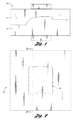
- FIG. 2 a top plan view of the mould 10 of Figure 1 is illustrated.
- a heated resin is injected into the mould 10 through a resin inlet such as a gate.
- the heated resin has moulded-in-colour so that a secondary painting operation is not required.
- the heated resin and the colourant may be separately injected into the mould 10.
- the resin may have material properties comparable with a thermoplastic polyolefin (TPO) or a polycarbonate-acrylonitrile butadiene styrene (PC/ABS).
- the resin may contain metallic moulded-in-colour for vehicle panel applications for use in the interior of the vehicle, for example.
- Using a metallic moulded-in-colour resin in a typical mould creates large amounts of surface defects, which are not visually appealing.
- the metallic moulded-in-colour resin may achieve a low gloss, quality, metallic appearance once injection-moulded or compression-moulded.
- the resulting vehicle panel delivers an enhanced metallic appearance over paint and offers a low-cost option to using aluminium and/or decorative films.
- the mould 10 of Figure 2 is illustrated in cross-section taken along line 3-3.
- the mould 10 has a cavity 12, which is stationary and a core 14 which is moveable relative to the cavity 12.
- the cavity 12 may also be moveable relative to the core 14.
- the mould 10 is illustrated in a closed position while a vehicle panel 16 is being formed.
- the vehicle panel has an appearance portion or visible side 21 and a concealed portion or back side 23.
- the cavity 12 has a very smooth first forming surface 20 for cooperating with a second forming surface 22 of the core 14.
- the first forming surface 20 may be a polished surface.
- the first forming surface 20 of the cavity 12 and the second forming surface 22 collectively provide an outer boundary for the vehicle panel 16. In another embodiment, three or more forming surfaces are provided to collectively define the outer boundary of a vehicle panel.
- Heated resin flows over the first forming surface 20 and the second forming surface 22 to fabricate a vehicle panel 16. The heated resin may be introduced into the mould 10 in any suitable known manner.
- the second forming surface 22 of the core 14 is free of any protuberances such as ancillary structural elements, any features that are not required for an appearance of an exposed, visible side 21 of the vehicle panel 16 or any changes in a concealed side 23 without corresponding changes in the exposed, visible side 21.
- the protuberance free second forming surface 22 allows heated resin to freely flow over the second forming surface 22 without disturbance.
- the vehicle panel 16 formed in the mould 10 is free of visible knit lines, flow lines and sink marks on the exposed, appearance portion in the form of visible side 21 of the vehicle panel 16.
- Ideal surface characteristics for the visible side 21 are, a smooth blemish free surface with minimal surface irregularities and is desired so that the vehicle panel 16 is visually pleasing.
- the exposed, visible side 21 is visible when mounted on a vehicle.
- the design of the second forming surface 22 eliminates all protuberances formed in the second forming surface 22, including any ancillary structural elements.
- ancillary structural elements include, but are not limited to, brackets, ribs, gussets, bosses, connecting members, retention members, fasteners, and/or push-pins.
- the ancillary structural elements are separately formed and welded to the vehicle panel at a welding station, which is illustrated in Figure 4 and generally referenced by numeral 18.
- a laser welding station 18 is illustrated as one example of a welding station. It will be appreciated that any suitable welding station is contemplated within the scope of the present invention.
- the laser welding station 18 has a robot 25 to support a laser welding end effecter 27.
- the laser welding station 18 has a first weld fixture 29 to support a vehicle panel 16 and a second weld fixture 31 to support an ancillary structural component 24. It will be appreciated that any suitable first and second weld fixtures may be used.
- the laser end effecter 27 on the robot 25 produces a laser beam 33 to produce a weld zone 35 between the vehicle panel 16 and the ancillary structural component 24.
- the laser 27 may rotate about the second weld fixture 31, as indicated by an arcuate arrow, to adequately join the vehicle panel 16 and the ancillary structural component 24.
- One ancillary structural component is a rib 24, which extends along a length of the vehicle panel 16.
- Another ancillary structural component is a connecting member 24 to connect the vehicle panel 16 to the vehicle once the connecting member 24 is welded to the vehicle panel 16.
- a further ancillary structural component 26 is a push-pin 26 (fir tree retainer).
- the push-pin 26 facilitates retention of the vehicle panel 16 on a vehicle once the push-pin 26 is welded to the vehicle panel 16.
- Bracket 28 Another ancillary structural component 28 is a bracket 28.
- the bracket 28 is utilized to removably attach the vehicle panel 16 to a vehicle once the bracket 28 is welded to the vehicle panel 16.
- gusset 30 supports a corner of the vehicle panel 16 once the gusset 30 is welded to the vehicle panel 16.
- the vehicle panel 16 is formed free of protuberances on the concealed side 23 to facilitate ideal surface characteristics on the exposed, visible side 21. Since the vehicle panel 16 is formed without protuberances on the concealed side 23, the ancillary structural components 24-30 are not integrally formed with the vehicle panel 16.
- the ancillary structural components 24-30 are individually moulded.
- the ancillary structural components 24-30 may be injection-moulded, compression-moulded, vacuum-moulded or extruded.
- the ancillary structural components 24-30 may be fabricated in any suitable known manner so that the ancillary structural components 24-20 may be welded to the vehicle panel 16.
- the ancillary structural components may be, but are not limited to being brackets, ribs, gussets, bosses, connecting members, retention members, fasteners, and/or push-pins. Any known ancillary structural components may be utilized within the scope of the present invention.
- a plurality of structural components is provided and the plurality of structural components are all welded to the vehicle panel 16.
- the ancillary structural components may be all identical, may differ in size and/or shape, or may be varying amounts of differing types altogether of ancillary structural components.
- the ancillary structural components 24-30 are formed while the vehicle panel 16 is produced. In another embodiment, the ancillary structural components 24-30 are fabricated at a different time and/or place from the vehicle panel 16.
- the vehicle panel 16 is suitably transported from the mould 10 to the welding station 18, as illustrated in Figure 4 .
- the ancillary structural components 24-30 are transported to the welding station 18 where the ancillary structural components 24-30 are welded to the vehicle panel 16.
- the ancillary structural components 24-30 are laser welded to the vehicle panel 16. In another embodiment, the ancillary structural components 24-30 are friction welded to the vehicle panel. Any known laser welding, friction welding or other thermoplastic joining station may be utilized so that the vehicle panel 16 and the ancillary structural components 24-30 are joined together, as depicted in Figure 6 . Any known manner of joining preformed ancillary structural components 24-30 to the preformed vehicle panel 16 is contemplated within the scope of the present invention.
- both the vehicle panel 16 and the ancillary structural components 24-30 should have overlapping melting temperatures.
- the overlapping melting temperatures of the vehicle panel 16 and the ancillary structural components 24-30 correspond with a temperature the welding station produces when the vehicle panel 16 and ancillary structural components 24-30 are placed under a laser of the laser welding station for a specified period of time.
- FIG. 7 an enlarged partial view of a vehicle panel 16 is illustrated joined together with an ancillary structural component 24.
- a weld zone 35 exists between the vehicle panel 16 and the ancillary structural component 24 that does not disrupt the exposed, visible side 21 of the vehicle panel 16.
- An adequate penetration weld may be employed so that the weld does not alter the finish of an exposed, visible side 21 of the vehicle panel 16.
- a method for creating a moulded-in-colour panel in a mould includes providing a mould having a first mould member and a second mould member.
- One of the first mould member and the second mould member has an appearance portion forming surface and the other of the first mould member and the second mould member has a concealed portion forming surface corresponding with the appearance portion forming surface.
- the concealed portion forming surface forms a concealed portion of a panel and is free of any protuberances and ancillary structural members for facilitating ideal surface characteristics of an appearance portion of the panel.
- Moulded-in-colour resin is injected in the mould and cooled to form a moulded-in-colour panel. At least one ancillary structural member is welded to the concealed portion of the panel.
- a moulded-in-colour panel is disclosed.
- the moulded-in-colour panel is formed providing a mould having a first mould member and a second mould member.
- One of the first mould member and the second mould member has an appearance portion forming surface and the other of the first mould member and the second mould member has a concealed portion forming surface corresponding with the appearance portion forming surface for forming a concealed portion of a panel.
- the concealed portion forming surface is free of any protuberances and ancillary structural members for facilitating ideal surface characteristics of an appearance portion of the panel.
- Moulded-in-colour resin is injected in the mould and the moulded-in-colour resin is cooled to form a moulded-in-colour panel.
- At least one ancillary structural member is welded to the concealed portion of the panel.
- a system for creating a moulded-in-colour element in a mould has an injection moulding machine having a first mould member and a second mould member.
- One of the first mould member and the second mould member has an appearance portion forming surface and the other of the first mould member and the second mould member has a concealed portion forming surface corresponding with the appearance portion forming surface for forming a concealed portion of a panel.
- the concealed portion forming surface is free of any protuberances and ancillary structural members for facilitating ideal surface characteristics of an appearance portion of the panel.
- Moulded-in-colour resin can be injected in the mould at a sufficient flow rate so that the moulded-in-colour resin flows without disruption over the first mould member and second mould member to form a moulded-in-colour element to facilitate ideal surface characteristics of the appearance portion of the moulded-in-colour element.
- the system includes a laser welding station to weld at least one accessory on the moulded-in-colour element.
Landscapes
- Engineering & Computer Science (AREA)
- Mechanical Engineering (AREA)
- Physics & Mathematics (AREA)
- Optics & Photonics (AREA)
- Health & Medical Sciences (AREA)
- Electromagnetism (AREA)
- Toxicology (AREA)
- Robotics (AREA)
- Manufacturing & Machinery (AREA)
- Injection Moulding Of Plastics Or The Like (AREA)
- Moulds For Moulding Plastics Or The Like (AREA)
Abstract
Description
- The present invention relates to moulded-in-colour panels and moulds for creating moulded-in-colour panels.
- Vehicle panels are an example of moulded-in-colour panels. Vehicle panels may be on the interior or exterior of a vehicle, commonly have surfaces, which are exposed to a viewable environment. These exposed surfaces are often referred to as class-A surfaces. It is desirable to create these class-A surfaces to have few or no surface defects or flaws when compared to non class-A surfaces. Since class-A surfaces are exposed to a viewable environment these surfaces are formed using tighter tolerances and greater detail. Non class-A surfaces are not exposed in the viewable environment and may have visible surface defects and flaws.
- Vehicle panels with class-A surfaces are not typically injection-moulded or compression-moulded unless the vehicle panels are painted in a secondary painting operation, covering surface defects. Painting the vehicle panel in a secondary painting operation requires additional time and cost to create the vehicle panel. Paint is also susceptible to peeling, chipping, blistering and/or de-lamination.
- Moulded-in-colour plastics are a lower cost option for programs to consider instead of current painted technologies and/or other decorative alternatives, such as paint film or other laminates. Moulded-in-colour plastics are also environmentally friendly because moulded-in-colour plastics do not require a secondary painting process so moulded-in-colour plastics may be easily recycled and manufacturing of moulded-in-colour plastics does not generate volatile organic compounds.
- It is an object of this invention to provide a method for creating a moulded-in-colour panel.
- According to a first aspect of the invention there is provided a method for manufacturing a moulded-in-colour panel the method comprising providing a mould having a first mould member and a second mould member wherein one of the first mould member and the second mould member has an appearance portion forming surface and the other of the first mould member and the second mould member has a concealed portion forming surface corresponding to the appearance portion forming surface for forming a concealed portion of the moulded-in-colour panel, injecting moulded-in-colour resin into the mould and cooling the moulded-in-colour resin to form a moulded-in-colour panel characterised in that the concealed portion forming surface has a substantially smooth surface free from surface discontinuities so as to minimise surface disturbances in the appearance portion of the moulded-in-colour panel and the method further comprises attaching at least one ancillary structural member to the concealed portion of the moulded-in-colour panel after moulding of the moulded-in-colour panel is complete.
- Injecting moulded-in-colour resin may comprise injecting moulded-in-colour metallic resin.
- The appearance portion may be a front surface of the moulded-in-colour panel and the concealed portion may be a back surface of the moulded-in-colour panel.
- A substantially smooth surface free from surface discontinuities may be a surface free of any protuberances and ancillary structural members.
- Attaching at least one ancillary structural member to the concealed portion of the panel may comprise welding at least one ancillary structural member to the concealed portion of the panel
- The method may further comprise ejecting the moulded-in-colour panel from the mould before attaching the at least one ancillary structural member to the concealed portion of the moulded-in-colour panel.
- The method may further comprise forming the at least one ancillary structural member ready for attachment to the concealed portion of the moulded-in-colour panel.
- Forming may comprise injection moulding the at least one ancillary structural member.
- Attaching at least one ancillary structural member to the concealed portion of the panel may comprise laser welding the at least one ancillary structural member to the concealed surface of the moulded-in-colour panel.
- The method may comprise injection moulding the at least one ancillary structural member prior to welding the at least one ancillary structural member to the concealed portion of the moulded-in-colour panel.
- The method may further comprise conveying the moulded-in-colour panel to a welding station to weld the at least one ancillary structural member to the concealed portion of the moulded-in-colour panel.
- The mould may have a cavity as the first mould member and a core as the second mould member and the cavity may have a very smooth forming surface for forming the appearance portion of the moulded-in-colour panel and the core may have a generally smooth forming surface for forming the concealed portion of the moulded-in-colour panel.
- A very smooth forming surface may be a polished surface.
- A generally smooth forming surface may be a surface without protuberances or projections.
- According to a second aspect of the invention there is provided moulded-in-colour panel in which the moulded-in-colour panel is formed by a method in accordance with said first aspect of the invention.
- The moulded-in-colour panel may be a moulded-in-colour exterior panel for a motor vehicle.
- According to a third aspect of the invention there is provided a system for manufacturing a moulded-in-colour element in a mould, the system comprising an injection moulding machine having a first mould member and a second mould member wherein one of the first mould member and the second mould member has an appearance portion forming surface and the other of the first mould member and the second mould member has a concealed portion forming surface corresponding with the appearance portion forming surface for forming a concealed portion, characterised in that the system further comprises a laser welding station to weld after moulding of the moulded-in-colour element at least one ancillary member to the concealed portion of the moulded-in-colour element and that the concealed portion forming surface is substantially free of any surface discontinuities so that when moulded-in-colour resin is injected into the mould it can flow freely without disruption over the first mould member and the second mould member so as to form the moulded-in-colour element with ideal surface characteristics on the appearance portion of the moulded-in-colour element.
- A surface free of any surface discontinuities may be a surface free of any protuberances and ancillary members.
- Metallic moulded-in-colour resin may be injected in the mould.
- The moulded-in-colour element may be a metallic moulded-in-colour element.
- The metallic moulded-in-colour element may be a metallic moulded-in-colour exterior panel for a motor vehicle.
- The invention will now be described by way of example with reference to the accompanying drawing of which:-
-
Figure 1 is a side elevation view of a mould; -
Figure 2 is top plan view of the mould ofFigure 1 ; -
Figure 3 is a cross-section view of the mould ofFigure 2 taken along line 3-3 onFigure 2 ; -
Figure 4 is a schematic view of a welding station embodiment for joining a panel and a structural component together; -
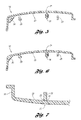
Figure 5 is a cross-section view of a panel formed in the mould ofFigure 3 and a plurality of structural components; -
Figure 6 is another cross-section view of the panel and the plurality of structural components ofFigure 5 joined together; and -
Figure 7 is an enlarged partial cross-section view of a panel joined together with a structural component. - As required, detailed embodiments of the present invention are disclosed herein; however, it is to be understood that the disclosed embodiments are exemplary of the invention that may be embodied in various and alternative forms. The figures are not necessarily to scale and some features may be exaggerated or minimized to show details of particular components.
- Moulded-in-colour panels may be formed using injection-moulding or compression-moulding. When forming moulded-in-colour panels, creating class-A surfaces results in a visible appearance of knit lines, mould flow lines, and sink marks. Although moulded-in-colour plastics offer benefits, it is still extremely difficult to mould parts in colour without visible appearance of knit lines, flow lines or sink marks on a class-A surface. In addition, when metallic moulded-in-colour resin is utilized, creating a defect-free class-A surface is extremely difficult because metallic moulded-in-colour resin has a high propensity for surface defects.
- Referring now to
Figure 1 , amould 10 for creating a moulded-in-colour panel 16 is illustrated and referenced generally bynumeral 10. Thepanel 16 may be any suitable moulded-in-colour panel and in one embodiment, the panel is avehicle panel 16 which is employed on an interior or exterior of a vehicle. Of course, any moulded-in-colour panel is contemplated within the scope of the present invention. - The
mould 10 has afirst mould half 12 and asecond mould half 14. In another embodiment, themould 10 may have three or more mould portions, which collectively form themould 10. Any number of mould portions is contemplated within the scope of the present invention. - In one embodiment, the
first mould half 12 is referred to as a cavity because thefirst mould half 12 may have a substantial recess for receiving thesecond mould half 14. Thesecond mould half 14 is referred to as a core because thesecond mould half 14 has a substantial projection which is received in thecavity 12. - The
core 14 may be moveable relative to thecavity 12. By providing astationary cavity 12 and amoveable core 14, a vehicle panel may be retained within themould 10 on thecore 14 after moulding the vehicle panel, which may be generally easily ejected or removed after themould 10 is opened. It is also contemplated within the scope of the invention that thecavity 12 may be moveable while thecore 14 is stationary. If three or more mould portions are employed, at least one mould portion may be moveable relative to at least a second mould portion. - Referring now to
Figure 2 , a top plan view of themould 10 ofFigure 1 is illustrated. To create thevehicle panel 16, a heated resin is injected into themould 10 through a resin inlet such as a gate. - The heated resin has moulded-in-colour so that a secondary painting operation is not required. In one embodiment, the heated resin and the colourant may be separately injected into the
mould 10. The resin may have material properties comparable with a thermoplastic polyolefin (TPO) or a polycarbonate-acrylonitrile butadiene styrene (PC/ABS). - The resin may contain metallic moulded-in-colour for vehicle panel applications for use in the interior of the vehicle, for example. Using a metallic moulded-in-colour resin in a typical mould creates large amounts of surface defects, which are not visually appealing. The metallic moulded-in-colour resin may achieve a low gloss, quality, metallic appearance once injection-moulded or compression-moulded. The resulting vehicle panel delivers an enhanced metallic appearance over paint and offers a low-cost option to using aluminium and/or decorative films.
- Referring now to
Figure 3 , themould 10 ofFigure 2 is illustrated in cross-section taken along line 3-3. Themould 10 has acavity 12, which is stationary and a core 14 which is moveable relative to thecavity 12. Thecavity 12 may also be moveable relative to thecore 14. Themould 10 is illustrated in a closed position while avehicle panel 16 is being formed. The vehicle panel has an appearance portion orvisible side 21 and a concealed portion or backside 23. - The
cavity 12 has a very smooth first formingsurface 20 for cooperating with a second formingsurface 22 of thecore 14. The first formingsurface 20 may be a polished surface. The first formingsurface 20 of thecavity 12 and the second formingsurface 22 collectively provide an outer boundary for thevehicle panel 16. In another embodiment, three or more forming surfaces are provided to collectively define the outer boundary of a vehicle panel. Heated resin flows over the first formingsurface 20 and the second formingsurface 22 to fabricate avehicle panel 16. The heated resin may be introduced into themould 10 in any suitable known manner. - The second forming
surface 22 of thecore 14 is free of any protuberances such as ancillary structural elements, any features that are not required for an appearance of an exposed,visible side 21 of thevehicle panel 16 or any changes in aconcealed side 23 without corresponding changes in the exposed,visible side 21. The protuberance free second formingsurface 22 allows heated resin to freely flow over the second formingsurface 22 without disturbance. - Since the heated resin flows without disturbance over the second forming
surface 22, thevehicle panel 16 formed in themould 10 is free of visible knit lines, flow lines and sink marks on the exposed, appearance portion in the form ofvisible side 21 of thevehicle panel 16. Ideal surface characteristics for thevisible side 21 are, a smooth blemish free surface with minimal surface irregularities and is desired so that thevehicle panel 16 is visually pleasing. - The exposed,
visible side 21 is visible when mounted on a vehicle. To produce the visuallypleasing vehicle panel 16, the design of the second formingsurface 22 eliminates all protuberances formed in the second formingsurface 22, including any ancillary structural elements. Examples of ancillary structural elements include, but are not limited to, brackets, ribs, gussets, bosses, connecting members, retention members, fasteners, and/or push-pins. The ancillary structural elements are separately formed and welded to the vehicle panel at a welding station, which is illustrated inFigure 4 and generally referenced bynumeral 18. - Referring to
Figure 4 , alaser welding station 18 is illustrated as one example of a welding station. It will be appreciated that any suitable welding station is contemplated within the scope of the present invention. Thelaser welding station 18 has arobot 25 to support a laserwelding end effecter 27. Thelaser welding station 18 has afirst weld fixture 29 to support avehicle panel 16 and asecond weld fixture 31 to support an ancillarystructural component 24. It will be appreciated that any suitable first and second weld fixtures may be used. Thelaser end effecter 27 on therobot 25 produces alaser beam 33 to produce aweld zone 35 between thevehicle panel 16 and the ancillarystructural component 24. Thelaser 27 may rotate about thesecond weld fixture 31, as indicated by an arcuate arrow, to adequately join thevehicle panel 16 and the ancillarystructural component 24. - With reference to
Figure 5 , avehicle panel 16 formed in themould 10 ofFigures 1-3 and ancillarystructural components 24 to 30 are illustrated. - One ancillary structural component is a
rib 24, which extends along a length of thevehicle panel 16. - Another ancillary structural component is a connecting
member 24 to connect thevehicle panel 16 to the vehicle once the connectingmember 24 is welded to thevehicle panel 16. - A further ancillary
structural component 26 is a push-pin 26 (fir tree retainer). The push-pin 26 facilitates retention of thevehicle panel 16 on a vehicle once the push-pin 26 is welded to thevehicle panel 16. - Another ancillary
structural component 28 is abracket 28. Thebracket 28 is utilized to removably attach thevehicle panel 16 to a vehicle once thebracket 28 is welded to thevehicle panel 16. - Yet another ancillary
structural component 30 is agusset 30. Thegusset 30 supports a corner of thevehicle panel 16 once thegusset 30 is welded to thevehicle panel 16. - It will be appreciated that more or less ancillary components may be fastened to the
panel 16 depending upon the application. - As discussed above, the
vehicle panel 16 is formed free of protuberances on theconcealed side 23 to facilitate ideal surface characteristics on the exposed,visible side 21. Since thevehicle panel 16 is formed without protuberances on theconcealed side 23, the ancillary structural components 24-30 are not integrally formed with thevehicle panel 16. - In one embodiment, the ancillary structural components 24-30 are individually moulded. The ancillary structural components 24-30 may be injection-moulded, compression-moulded, vacuum-moulded or extruded. The ancillary structural components 24-30 may be fabricated in any suitable known manner so that the ancillary structural components 24-20 may be welded to the
vehicle panel 16. - The ancillary structural components may be, but are not limited to being brackets, ribs, gussets, bosses, connecting members, retention members, fasteners, and/or push-pins. Any known ancillary structural components may be utilized within the scope of the present invention. In one embodiment, a plurality of structural components is provided and the plurality of structural components are all welded to the
vehicle panel 16. The ancillary structural components may be all identical, may differ in size and/or shape, or may be varying amounts of differing types altogether of ancillary structural components. - In one embodiment, the ancillary structural components 24-30 are formed while the
vehicle panel 16 is produced. In another embodiment, the ancillary structural components 24-30 are fabricated at a different time and/or place from thevehicle panel 16. Thevehicle panel 16 is suitably transported from themould 10 to thewelding station 18, as illustrated inFigure 4 . The ancillary structural components 24-30 are transported to thewelding station 18 where the ancillary structural components 24-30 are welded to thevehicle panel 16. - In one embodiment, the ancillary structural components 24-30 are laser welded to the
vehicle panel 16. In another embodiment, the ancillary structural components 24-30 are friction welded to the vehicle panel. Any known laser welding, friction welding or other thermoplastic joining station may be utilized so that thevehicle panel 16 and the ancillary structural components 24-30 are joined together, as depicted inFigure 6 . Any known manner of joining preformed ancillary structural components 24-30 to the preformedvehicle panel 16 is contemplated within the scope of the present invention. - To weld the
vehicle panel 16 and the ancillary structural components 24-30 together, both thevehicle panel 16 and the ancillary structural components 24-30 should have overlapping melting temperatures. In one embodiment, the overlapping melting temperatures of thevehicle panel 16 and the ancillary structural components 24-30 correspond with a temperature the welding station produces when thevehicle panel 16 and ancillary structural components 24-30 are placed under a laser of the laser welding station for a specified period of time. - Referring now to
Figure 7 , an enlarged partial view of avehicle panel 16 is illustrated joined together with an ancillarystructural component 24. Aweld zone 35 exists between thevehicle panel 16 and the ancillarystructural component 24 that does not disrupt the exposed,visible side 21 of thevehicle panel 16. An adequate penetration weld may be employed so that the weld does not alter the finish of an exposed,visible side 21 of thevehicle panel 16. - Therefore in summary, a method for creating a moulded-in-colour panel in a mould is disclosed. The method includes providing a mould having a first mould member and a second mould member. One of the first mould member and the second mould member has an appearance portion forming surface and the other of the first mould member and the second mould member has a concealed portion forming surface corresponding with the appearance portion forming surface. The concealed portion forming surface forms a concealed portion of a panel and is free of any protuberances and ancillary structural members for facilitating ideal surface characteristics of an appearance portion of the panel. Moulded-in-colour resin is injected in the mould and cooled to form a moulded-in-colour panel. At least one ancillary structural member is welded to the concealed portion of the panel.
- In another embodiment, a moulded-in-colour panel is disclosed. The moulded-in-colour panel is formed providing a mould having a first mould member and a second mould member. One of the first mould member and the second mould member has an appearance portion forming surface and the other of the first mould member and the second mould member has a concealed portion forming surface corresponding with the appearance portion forming surface for forming a concealed portion of a panel. The concealed portion forming surface is free of any protuberances and ancillary structural members for facilitating ideal surface characteristics of an appearance portion of the panel. Moulded-in-colour resin is injected in the mould and the moulded-in-colour resin is cooled to form a moulded-in-colour panel. At least one ancillary structural member is welded to the concealed portion of the panel.
- In another embodiment, a system for creating a moulded-in-colour element in a mould is disclosed. The system has an injection moulding machine having a first mould member and a second mould member. One of the first mould member and the second mould member has an appearance portion forming surface and the other of the first mould member and the second mould member has a concealed portion forming surface corresponding with the appearance portion forming surface for forming a concealed portion of a panel. The concealed portion forming surface is free of any protuberances and ancillary structural members for facilitating ideal surface characteristics of an appearance portion of the panel. Moulded-in-colour resin can be injected in the mould at a sufficient flow rate so that the moulded-in-colour resin flows without disruption over the first mould member and second mould member to form a moulded-in-colour element to facilitate ideal surface characteristics of the appearance portion of the moulded-in-colour element. The system includes a laser welding station to weld at least one accessory on the moulded-in-colour element.
- It will be appreciated by those skilled in the art that although the invention has been described by way of example with reference to one or more embodiments it is not limited to the disclosed embodiments and that one or more modifications to the disclosed embodiments or alternative embodiments could be constructed without departing from the scope of the invention as set out in the appended claims.
Claims (15)
- A method for manufacturing a moulded-in-colour panel (16) the method comprising providing a mould (10) having a first mould member (12) and a second mould member (14) wherein one of the first mould member and the second mould member has an appearance portion forming surface (20)and the other of the first mould member and the second mould member has a concealed portion forming surface (22) corresponding to the appearance portion forming surface (20) for forming a concealed portion (23) of the moulded-in colour panel (16), injecting moulded-in-colour resin into the mould (10) and cooling the moulded-in-colour resin to form a moulded-in-colour panel (16) characterised in that the concealed portion forming surface (22) has a substantially smooth surface free from surface discontinuities so as to minimise surface disturbances in the appearance portion (21) of the panel (16) and the method further comprises attaching at least one ancillary structural member (24, 26, 28, 30) to the concealed portion (23) of the moulded-in-colour panel (16) after moulding of the moulded-in-colour panel (16) is complete.
- A method as claimed in claim 1 wherein the method further comprises ejecting the moulded-in-colour panel (16) from the mould (10) before attaching the at least one ancillary structural member (24, 26, 28, 30) to the concealed portion (23) of the moulded-in-colour panel (16).
- A method as claimed in claim 1 or in claim 2 wherein the method further comprises forming the at least one ancillary structural member (24, 26, 28, 30) ready for attachment to the concealed portion (23) of the moulded-in-colour panel (16).
- A method as claimed in claim 3 wherein forming comprises injection moulding the at least one ancillary structural member (24, 26, 28, 30).
- A method as claimed in any of claims 1 to 4 wherein attaching at least one ancillary structural member (24, 26, 28, 30) to the concealed portion (23) of the moulded-in-colour panel (16) comprises laser welding the at least one ancillary structural member (24, 26, 28, 30) to the concealed surface (23) of the moulded-in-colour panel (16).
- A method as claimed in claim 5 wherein the method further comprises conveying the moulded-in-colour panel (16) to a welding station (18) to weld the at least one ancillary structural member (24, 26, 28, 30) to the concealed portion (23) of the moulded-in-colour panel (16).
- A method as claimed in any of claims 1 to 6 wherein the mould (10) has a cavity as the first mould member (12) and a core as the second mould member (14) and the cavity has a very smooth forming surface (20) for forming the appearance portion (21) of the moulded-in-colour panel (16) and the core has a generally smooth forming surface (22) for forming the concealed portion (23) of the moulded-in-colour panel (16).
- A moulded-in-colour panel characterised in that the moulded-in-colour panel (16) is formed by a method as claimed in any of claims 1 to 7.
- A moulded-in-colour panel wherein the moulded-in-colour panel is a moulded-in-colour exterior panel for a motor vehicle.
- A system for manufacturing a moulded-in-colour element in a mould, the system comprising an injection moulding machine having a first mould member and a second mould member wherein one of the first mould member and the second mould member has an appearance portion forming surface (20) and the other of the first mould member and the second mould member has a concealed portion forming surface (22) corresponding with the appearance portion forming surface (20) for forming a concealed portion (23), characterised in that the system further comprises a laser welding station (18) to weld after moulding of the moulded-in-colour element at least one ancillary member (24, 26, 28, 30) to the concealed portion (23) of the moulded-in-colour element (16) and that the concealed portion forming surface(22) is substantially free of any surface discontinuities so that when moulded-in-colour resin is injected into the mould (10) it can flow freely without disruption over the first mould member and the second mould member so as to form the moulded-in-colour element (16) with ideal surface characteristics on the appearance portion (21) of the moulded-in-colour element (16).
- A method of moulding a moulded-in-colour panel comprising:providing a mould having a first mould member and a second mould member wherein one of the first mould member and the second mould member has an appearance portion forming surface and the other of the first mould member and the second mould member has a concealed portion forming surface corresponding with the appearance portion forming surface for forming a concealed portion of a panel, the concealed portion forming surface being free of any protuberances and ancillary structural members for facilitating ideal surface characteristics of an appearance portion of the panel;injecting moulded-in-colour resin in the mould;cooling the moulded-in-colour resin to form a moulded-in-colour panel; andwelding at least one ancillary structural member to the concealed portion of the panel.
- The method of claim 11, further comprising injecting moulded-in-colour metallic resin.
- The method of claim 11 or 12, further comprising laser welding the at least one ancillary structural member to the back surface of the moulded-in-colour panel.
- The method of claim 11 to 13, further comprising injection moulding the at least one ancillary structural member prior to welding the at least one ancillary structural member to the back surface of the moulded-in-colour panel.
- The method of claim 11 to 14, further comprising ejecting the moulded-in-colour panel before welding the at least one ancillary structural member to the back surface of the moulded-in-colour panel.
Applications Claiming Priority (1)
| Application Number | Priority Date | Filing Date | Title |
|---|---|---|---|
| US11/766,813 US20080318052A1 (en) | 2007-06-22 | 2007-06-22 | Molded-in-color panel and method for molding |
Publications (2)
| Publication Number | Publication Date |
|---|---|
| EP2006066A2 true EP2006066A2 (en) | 2008-12-24 |
| EP2006066A3 EP2006066A3 (en) | 2009-11-18 |
Family
ID=39769416
Family Applications (1)
| Application Number | Title | Priority Date | Filing Date |
|---|---|---|---|
| EP20080157984 Withdrawn EP2006066A3 (en) | 2007-06-22 | 2008-06-10 | Moulded-in-colour panel and method for moulding such |
Country Status (3)
| Country | Link |
|---|---|
| US (2) | US20080318052A1 (en) |
| EP (1) | EP2006066A3 (en) |
| CN (1) | CN101327650A (en) |
Families Citing this family (5)
| Publication number | Priority date | Publication date | Assignee | Title |
|---|---|---|---|---|
| US20080191379A1 (en) * | 2007-02-12 | 2008-08-14 | Ford Global Technologies, Llc | Molded-in-color vehicle panel and mold |
| US20080318051A1 (en) * | 2007-06-22 | 2008-12-25 | Ford Global Technologies, Llc | Molding system and molded-in-color panel |
| US20120061274A1 (en) * | 2010-09-14 | 2012-03-15 | Tyco Healthcare Group Lp | Hardpack Needle Package Laser Heat Seal |
| EP3078600B1 (en) * | 2013-12-06 | 2018-05-30 | Toyo Seikan Co., Ltd. | Vessel sealing device and sealing system |
| US20150336315A1 (en) * | 2014-05-20 | 2015-11-26 | Ford Global Technologies, Llc | Gas removal vacuum system for use with mold-in-color tooling |
Citations (5)
| Publication number | Priority date | Publication date | Assignee | Title |
|---|---|---|---|---|
| DE10059160A1 (en) | 2000-01-25 | 2001-08-02 | Fraunhofer Ges Forschung | Process and production of a permanent connection between a flat, lightweight plastic component with a quality surface and an element |
| DE10143564A1 (en) * | 2001-09-05 | 2003-03-20 | Basf Ag | Composite hollow profile product for vehicle body construction comprises a ribbed component connected to a plastic layer injected onto the rear side of a film layer |
| EP1382433A1 (en) * | 2002-07-16 | 2004-01-21 | JENOPTIK Automatisierungstechnik GmbH | Process for seaming plastic parts with a laser beam |
| EP1564067A1 (en) * | 2001-08-15 | 2005-08-17 | Dow Global Technologies Inc. | Improved seating system |
| FR2876945A1 (en) * | 2004-10-27 | 2006-04-28 | Mecaplast Sam Sa Monegasque | Reinforced thermoplastic component e.g. for motor vehicle interior load-bearing panel has main body and reinforcing elements of same or compatible thermoplastics |
Family Cites Families (45)
| Publication number | Priority date | Publication date | Assignee | Title |
|---|---|---|---|---|
| US3909175A (en) * | 1973-03-08 | 1975-09-30 | Du Pont Canada | Injection moulding runner and process |
| US4039215A (en) * | 1976-05-17 | 1977-08-02 | U.S. Industries, Inc. | Auto molding with integrally molded connector |
| US4403933A (en) * | 1982-04-14 | 1983-09-13 | Fischer & Porter Company | Apparatus for injection-molding a liner onto a metal spool |
| US5342666A (en) * | 1986-10-28 | 1994-08-30 | Rexham Industries Corp. | Injection molded plastic article with integral weatherable pigmented film surface |
| US4832593A (en) * | 1988-01-25 | 1989-05-23 | Husky Injection Molding Systems Ltd. | Large nozzle for hot runner mold |
| US5037680A (en) * | 1989-07-10 | 1991-08-06 | Decoma International Inc. | Exterior automotive component with pigmented substrate and clear coating |
| JPH0712632B2 (en) * | 1990-02-23 | 1995-02-15 | 秀俊 横井 | In-mold vibration finishing removal method |
| US5178051A (en) * | 1991-12-18 | 1993-01-12 | Hughes Aircraft Company | Magnetic punch die retention for HTCC/LTCC fabrication |
| JP2788023B2 (en) * | 1995-11-29 | 1998-08-20 | 大日本印刷株式会社 | Injection molding simultaneous painting equipment |
| US6165407A (en) * | 1997-05-28 | 2000-12-26 | Mitsubishi Engineering-Plastics Corp. | Mold assembly for molding thermoplastic resin and method of manufacturing molded article of thermoplastic resin |
| US5985198A (en) * | 1997-07-30 | 1999-11-16 | Ford Motor Company | Method for molding a film-covered article |
| US6468458B1 (en) * | 1998-10-23 | 2002-10-22 | Textron Automotive Company Inc, | Method for forming a composite product |
| US6319438B1 (en) * | 1998-12-15 | 2001-11-20 | Guardian Automotive Trim, Inc. | Extruded automotive trim and method of making same |
| DE19903338C1 (en) * | 1999-01-28 | 2000-07-06 | Franz Josef Summerer | Pressure injection mold for rear-injection of decorative materials such as cloth, leather or sheet to form shell molding has replaceable combination cutting slide at edges, for rapid low cost replacement on wear |
| US6168231B1 (en) * | 1999-04-01 | 2001-01-02 | Daimlerchrysler Corporation | Two piece plastic vehicle panel construction |
| US6838027B2 (en) * | 1999-12-30 | 2005-01-04 | Delphi Technologies, Inc. | Method of making an interior trim panel |
| US20020156161A1 (en) * | 2000-02-11 | 2002-10-24 | Reiko Koshida | Thermoplastic resin compositions for laser welding and articles formed therefrom |
| US20060024476A1 (en) * | 2000-07-25 | 2006-02-02 | Richard Leland | Method of marking a skin for a vehicle interior panel |
| DE20115164U1 (en) * | 2001-09-13 | 2002-02-14 | Brose Fahrzeugteile GmbH & Co. Kommanditgesellschaft, Coburg, 96450 Coburg | Guide rail for a motor vehicle seat |
| DE10151847A1 (en) * | 2001-10-24 | 2003-05-08 | Bayer Ag | Laser absorbing soot molding compounds |
| US6568705B2 (en) * | 2001-10-29 | 2003-05-27 | Visteon Global Technologies, Inc. | Seamless door system for an airbag |
| JP4074618B2 (en) * | 2002-04-26 | 2008-04-09 | 株式会社プライムポリマー | Sound absorber, sound absorbing structure, and manufacturing method thereof |
| US7108311B2 (en) * | 2003-02-28 | 2006-09-19 | Lear Corporation | Method of forming a vehicle panel assembly |
| US7811497B2 (en) * | 2003-06-24 | 2010-10-12 | Johnson Controls Technology Company | Multi-color injection molded door panel and process |
| GB2408960B (en) * | 2003-12-12 | 2008-01-30 | Nokia Corp | In-mould labelling |
| US20050202210A1 (en) * | 2004-03-12 | 2005-09-15 | Andre Schulthess | Injection molding method, injection molding tool and object produced |
| JP4442325B2 (en) * | 2004-05-31 | 2010-03-31 | 東洋製罐株式会社 | Method for producing multilayer structure |
| JP4610238B2 (en) * | 2004-06-21 | 2011-01-12 | ダイセルポリマー株式会社 | Bonding method of resin moldings |
| DE102004040942A1 (en) * | 2004-08-24 | 2006-03-16 | Lisa Dräxlmaier GmbH | Method and device for the production of trim parts |
| CA2517940A1 (en) * | 2004-09-24 | 2006-03-24 | Ems-Chemie Ag | Injection molding method for manufacturing plastic parts |
| US20060068193A1 (en) * | 2004-09-29 | 2006-03-30 | Lear Corporation | Method and apparatus for making a trim panel with a self-skinning blown elastomer component |
| CN100455434C (en) * | 2004-09-30 | 2009-01-28 | 冷鹭浩 | A kind of plastic composite board and its manufacturing method |
| US20070126138A1 (en) * | 2005-12-07 | 2007-06-07 | Lear Corporation | Method and apparatus for making a part |
| US7387154B2 (en) * | 2006-02-24 | 2008-06-17 | Husky Injection Molding Systems Ltd. | Metallic-molding-material runner having equilibrated flow |
| DE102006034603A1 (en) * | 2006-07-26 | 2008-01-31 | Schoeller Arca Systems Services Gmbh | Plastic containers, in particular bottle crates, with a shell structure |
| US7862671B2 (en) * | 2007-01-11 | 2011-01-04 | Dow Global Technologies Inc. | Welding of a polymeric material and structures formed thereby |
| US20080191379A1 (en) * | 2007-02-12 | 2008-08-14 | Ford Global Technologies, Llc | Molded-in-color vehicle panel and mold |
| ATE437277T1 (en) * | 2007-05-08 | 2009-08-15 | Huf Huelsbeck & Fuerst Gmbh | METHOD FOR PRODUCING AN OUTSIDE DOOR HANDLE |
| US20080318051A1 (en) * | 2007-06-22 | 2008-12-25 | Ford Global Technologies, Llc | Molding system and molded-in-color panel |
| JP5157675B2 (en) * | 2008-06-24 | 2013-03-06 | スズキ株式会社 | Mold for injection molding and molding method of resin molded product |
| KR101254860B1 (en) * | 2008-09-30 | 2013-04-15 | 토와 가부시기가이샤 | Resin sealing compression molding method for electronic component and device therefor |
| KR101013911B1 (en) * | 2008-10-08 | 2011-02-14 | 기아자동차주식회사 | Crash pad for vehicle interior and its manufacturing apparatus |
| KR100933717B1 (en) * | 2009-05-20 | 2009-12-24 | 삼성전자주식회사 | Injection mold and injection molding method using the same |
| JP4623241B1 (en) * | 2009-05-28 | 2011-02-02 | 宇部興産機械株式会社 | Lamination molding apparatus and lamination molding method |
| CA2854615C (en) * | 2010-11-05 | 2017-01-24 | Lightweight Labs, Llc | Thermal processing and consolidation system and method |
-
2007
- 2007-06-22 US US11/766,813 patent/US20080318052A1/en not_active Abandoned
-
2008
- 2008-06-10 EP EP20080157984 patent/EP2006066A3/en not_active Withdrawn
- 2008-06-18 CN CNA2008101249533A patent/CN101327650A/en active Pending
-
2013
- 2013-04-29 US US13/872,486 patent/US20130248096A1/en not_active Abandoned
Patent Citations (5)
| Publication number | Priority date | Publication date | Assignee | Title |
|---|---|---|---|---|
| DE10059160A1 (en) | 2000-01-25 | 2001-08-02 | Fraunhofer Ges Forschung | Process and production of a permanent connection between a flat, lightweight plastic component with a quality surface and an element |
| EP1564067A1 (en) * | 2001-08-15 | 2005-08-17 | Dow Global Technologies Inc. | Improved seating system |
| DE10143564A1 (en) * | 2001-09-05 | 2003-03-20 | Basf Ag | Composite hollow profile product for vehicle body construction comprises a ribbed component connected to a plastic layer injected onto the rear side of a film layer |
| EP1382433A1 (en) * | 2002-07-16 | 2004-01-21 | JENOPTIK Automatisierungstechnik GmbH | Process for seaming plastic parts with a laser beam |
| FR2876945A1 (en) * | 2004-10-27 | 2006-04-28 | Mecaplast Sam Sa Monegasque | Reinforced thermoplastic component e.g. for motor vehicle interior load-bearing panel has main body and reinforcing elements of same or compatible thermoplastics |
Also Published As
| Publication number | Publication date |
|---|---|
| CN101327650A (en) | 2008-12-24 |
| US20130248096A1 (en) | 2013-09-26 |
| EP2006066A3 (en) | 2009-11-18 |
| US20080318052A1 (en) | 2008-12-25 |
Similar Documents
| Publication | Publication Date | Title |
|---|---|---|
| Thompson | Manufacturing processes for design professionals | |
| US7674414B2 (en) | In mold lamination of decorative products | |
| JP4088623B2 (en) | Molded part having fabric surface region and method for manufacturing the same | |
| TWI397466B (en) | Injection molding method for manufacturing plastic parts | |
| US20130248096A1 (en) | Molded-In-Color Panel And Method For Molding | |
| CA2139954A1 (en) | Paint film and methods for its manufacture | |
| Goodship et al. | Multi-material injection moulding | |
| MXPA03007200A (en) | Method for producing composite parts by multicomponent injection molding. | |
| US20190389097A1 (en) | Method of Making a Trim Component Having a Fibrous Decorative Covering | |
| JP2008507430A (en) | Multilayer film, sheet and method for producing article derived therefrom | |
| US20100167026A1 (en) | Decorative products having depth of image | |
| US20140147605A1 (en) | Method for producing a decorative part, and such a decorative part | |
| US8343409B2 (en) | Molding system and molded-in-color panel | |
| US20030194542A1 (en) | Panel with injection molded components and method of making same | |
| US20190389102A1 (en) | Method of Making a Trim Component Having an Edge-Wrapped, Fibrous Decorative Covering | |
| US20190389104A1 (en) | Method of Making a Vehicle Interior Component Having an Integral Airbag Component | |
| US12611998B2 (en) | Plastic cover comprising a coating layer | |
| US9090003B2 (en) | Molded-in-color vehicle panel and mold | |
| US6413460B1 (en) | Method of forming a partially covered panel | |
| KR20070008433A (en) | Method for producing a composite structural component | |
| Muccio | Plastic part technology | |
| US20080110549A1 (en) | Internal perimeter molding method and related article | |
| JP2014512282A (en) | Method for producing composite material member | |
| CA2257281A1 (en) | Process and device for making movable units of a plastic component | |
| JP7343361B2 (en) | Manufacturing method for resin molded products |
Legal Events
| Date | Code | Title | Description |
|---|---|---|---|
| PUAI | Public reference made under article 153(3) epc to a published international application that has entered the european phase |
Free format text: ORIGINAL CODE: 0009012 |
|
| AK | Designated contracting states |
Kind code of ref document: A2 Designated state(s): AT BE BG CH CY CZ DE DK EE ES FI FR GB GR HR HU IE IS IT LI LT LU LV MC MT NL NO PL PT RO SE SI SK TR |
|
| AX | Request for extension of the european patent |
Extension state: AL BA MK RS |
|
| PUAL | Search report despatched |
Free format text: ORIGINAL CODE: 0009013 |
|
| AK | Designated contracting states |
Kind code of ref document: A3 Designated state(s): AT BE BG CH CY CZ DE DK EE ES FI FR GB GR HR HU IE IS IT LI LT LU LV MC MT NL NO PL PT RO SE SI SK TR |
|
| AX | Request for extension of the european patent |
Extension state: AL BA MK RS |
|
| 17P | Request for examination filed |
Effective date: 20100325 |
|
| 17Q | First examination report despatched |
Effective date: 20100429 |
|
| AKX | Designation fees paid |
Designated state(s): DE FR GB SE |
|
| STAA | Information on the status of an ep patent application or granted ep patent |
Free format text: STATUS: THE APPLICATION IS DEEMED TO BE WITHDRAWN |
|
| 18D | Application deemed to be withdrawn |
Effective date: 20160119 |