EP2005814A1 - Combine threshing rotor inlet section - Google Patents
Combine threshing rotor inlet section Download PDFInfo
- Publication number
- EP2005814A1 EP2005814A1 EP08158532A EP08158532A EP2005814A1 EP 2005814 A1 EP2005814 A1 EP 2005814A1 EP 08158532 A EP08158532 A EP 08158532A EP 08158532 A EP08158532 A EP 08158532A EP 2005814 A1 EP2005814 A1 EP 2005814A1
- Authority
- EP
- European Patent Office
- Prior art keywords
- rotor
- inlet section
- rearwardly
- radially outwardly
- extending
- Prior art date
- Legal status (The legal status is an assumption and is not a legal conclusion. Google has not performed a legal analysis and makes no representation as to the accuracy of the status listed.)
- Withdrawn
Links
- 239000000463 material Substances 0.000 claims abstract description 60
- 230000004888 barrier function Effects 0.000 claims description 3
- 239000010902 straw Substances 0.000 abstract description 5
- 238000004804 winding Methods 0.000 abstract description 4
- 241000196324 Embryophyta Species 0.000 description 13
- 230000010006 flight Effects 0.000 description 6
- 235000013339 cereals Nutrition 0.000 description 5
- 238000003306 harvesting Methods 0.000 description 5
- 230000009471 action Effects 0.000 description 3
- 230000033001 locomotion Effects 0.000 description 3
- 230000007704 transition Effects 0.000 description 2
- 241000743339 Agrostis Species 0.000 description 1
- 244000075850 Avena orientalis Species 0.000 description 1
- 235000007319 Avena orientalis Nutrition 0.000 description 1
- 240000004296 Lolium perenne Species 0.000 description 1
- 241000219793 Trifolium Species 0.000 description 1
- 230000001154 acute effect Effects 0.000 description 1
- 238000000429 assembly Methods 0.000 description 1
- 230000000712 assembly Effects 0.000 description 1
- 230000008901 benefit Effects 0.000 description 1
- 238000010276 construction Methods 0.000 description 1
- 230000000694 effects Effects 0.000 description 1
- 230000006872 improvement Effects 0.000 description 1
- 238000001764 infiltration Methods 0.000 description 1
- 230000008595 infiltration Effects 0.000 description 1
- 244000043623 perennial rye grass Species 0.000 description 1
- 230000002093 peripheral effect Effects 0.000 description 1
- 230000002028 premature Effects 0.000 description 1
Images




Classifications
-
- A—HUMAN NECESSITIES
- A01—AGRICULTURE; FORESTRY; ANIMAL HUSBANDRY; HUNTING; TRAPPING; FISHING
- A01F—PROCESSING OF HARVESTED PRODUCE; HAY OR STRAW PRESSES; DEVICES FOR STORING AGRICULTURAL OR HORTICULTURAL PRODUCE
- A01F7/00—Threshing apparatus
- A01F7/02—Threshing apparatus with rotating tools
- A01F7/06—Threshing apparatus with rotating tools with axles in line with the feeding direction ; Axial threshing machines
Definitions
- the present invention relates generally to agricultural combine rotors, and more particularly, to a front bearing housing and front rotor inlet section combination having anti-wind features for preventing winding or wrapping of plant materials therearound, which features are improved and supplemented for providing a capability for pushing or conveying straw radially outwardly from adjacent to the front bearing, and also rearwardly therefrom.
- a well-known form of harvesting machine is a rotary combine.
- a typical combine includes a crop harvesting apparatus which reaps grain stalks and other plant materials and feeds them to a separating or threshing apparatus.
- the grain stalks or other crop and plant materials harvested in the field are moved rearwardly from a crop harvesting header assembly and introduced for threshing to the rotor assembly by a crop feeder assembly.
- the rotor assembly includes a generally tubular rotor housing mounted in the combine body.
- a driven rotor is coaxially mounted within the housing.
- the rotor comprises an infeed or inlet section and a cylindrical threshing section, and is supported at opposite ends by front and rear bearing assemblies.
- the cylindrical threshing section of the rotor and the rotor housing mount cooperating threshing elements which separate grain from other material in a threshing zone.
- the crop material is threshed as it spirals around the rotor threshing section and passes through openings in the rotor housing.
- rotary combine rotors include an infeed or inlet section impeller comprised of a series of impeller blades or flights arranged at a forward end of the rotor.
- the impeller flights rotate within a housing which is a part of the rotor housing.
- the generally linear movement of the crop materials received from the feeder assembly is converted by the rotating impeller flights into a rotating, circulatory movement, in a rearward and outward direction.
- a front bearing housing anti-wind element and/or front rotor inlet section which provides improved anti-wind characteristics, particularly with regard to long, wet straw and other crop material, and more particularly, which is operable for conveying such crop material radially outwardly and rearwardly away from the associated bearing supporting the inlet section.
- the rotor inlet section for a threshing rotor of an agricultural combine comprises a body adapted to be mounted on a front end of a rotor around a frontwardly and rearwardly extending rotational axis therethrough for rotation with the rotor in a predetermined rotational direction about the rotational axis, the body comprising:
- the apparatus supporting a front end of a rotor for an agricultural combine for rotation in a predetermined rotational direction about a rotational axis extending therethrough comprises:
- the protuberance will rotate through the space around the bearing housing, and any long elements of plant material, such as long wet straw in that space will be engaged by the edges and/or surfaces of the at least one slot, so as to be pushed or conveyed through the slot radially outwardly thereby, away from the bearing housing.
- the plant material can also be cut or ground up by repeated contact with one or more of the edges of the slot.
- the plant material will be engaged and pushed or conveyed rearwardly by the lip or shoulder along the outer circumferential surface of the body through a space between that surface and the shroud, to the impeller augers or flights of the rotor, for processing by the threshing system.
- plant material particularly the longer elements of plant material, such as straw and the like, which begins to wrap around the body of the inlet section so as to work into the space between the body of the inlet section and the shroud, will be forced rearwardly by the lip or shoulder. No straight line radial inward path exists for passage of plant material past the body and so as to wrap around the bearing housing or shaft.
- the positioning and rotation of the protuberance radially outwardly of the bearing housing in axial overlapping relation thereto, and the pushing or conveying of crop material radially outwardly away from the bearing housing by the one or more edges and/or surfaces of the at least one slot through the protuberance, in combination with the rearward pushing or conveying of the crop material around the radial outer periphery of the body through the space formed thereby with the inner periphery of the shroud, provides an improved capability for keeping long crop material from wrapping around the bearing housing and the shaft or other element supporting the rotor for rotation relative thereto.
- the radial outer periphery of the rotor inlet section extends onto the edge surface facing in the rotational direction of a pair of diametrically opposed extensions extending radially outwardly, each of the extensions being swept back relative to the rotational direction.
- the lip or shoulder extends then circumferentially partially around the radial outer periphery of the body from adjacent to the associated slot, to adjacent to the leading edge of one of the extensions, so as to push or convey the crop material into the path of rotation of the extensions, so as to be carried or propelled radially outwardly away from the central region of the inlet section and the bearing housing.
- Combine 10 includes a front portion 12 including front wheels 14, an operator cab 16, and an engine (not shown) suitably supported within a body 18.
- engine suitably supported within a body 18.
- the transfer of power from the engine to various driven components of combine 10 is effected conventionally.
- Combine 10 is provided with a crop harvesting header assembly 20 for cutting and gathering crop materials.
- Header assembly 20 cuts and directs the crop material into a crop feeder assembly 22 including a conveyor 24.
- Conveyor 24 carries the crop material upwardly toward a rotor assembly 26, which threshes grain from material other than the grain.
- Rotor assembly 26 is supported in a conventional manner inside body 18.
- Rotor assembly 26 includes a tubular rotor housing 28 mounted in a front to rear orientation in body 18.
- Rotor assembly 26 also includes a rotor 30 is mounted in housing 28 for rotation therein in a predetermined rotational direction about a rotational axis 32 through rotor 30 oriented at an acute angle to horizontal as shown.
- Rotor 30 is a hollow tube.
- Rotor 30 of rotor assembly 26 includes a front shaft 34 projecting concentrically about rotational axis 32 from a front infeed or inlet section 36, and a rear threshing section.
- Front inlet section 36 includes two helical impeller augers 40 extending therearound in a rearward direction from a front center portion 42 to the threshing section.
- Front inlet section 36 has a conical shape, extending radially outwardly relative to axis 32 rearwardly from adjacent to front center portion 42 to the threshing section.
- Rotor 30 is rotatable in rotor housing 28 in the rotational direction denoted by arrow 44 in Figure 3 .
- Each impeller auger 40 includes a flight having a leading edge 46 which extends radially outwardly with respect to axis 32 from a radial outer circumferential edge or periphery 48 of front center portion 42, and terminating at a radial outer edge 50. Edges 46 are raked or swept back in relation to rotational direction 44.
- Each impeller auger preferably has a helical pitch that increases in the rearward direction along the length thereof, which enables augers 40 to aggressively move plant material rearwardly from feeder assembly 22 during rotation of rotor 30, while leading edges 46 are disposed and rotate in closely spaced relation to an anti-wind shroud assembly 52 which supports and extends around and protects a front bearing housing 54 ( Figures 1 , 9 and 9B ) carrying a front bearing 56 ( Figures 9 and 9B ) for supporting shaft 34 and thus inlet section 36 of rotor 30 for rotation, as will be explained.
- Front center portion 42 of inlet section 36 preferably includes a front plate or a body 58 which is also part of rotor assembly 26, and is preferably welded or otherwise fixedly mounted onto inlet section 36.
- Body 58 is preferably of cast or forged construction, and shaft 34 is preferably integrally formed therewith.
- body 58 includes radial outer periphery 48, and at least one and preferably two frontwardly extending protuberances 60, that, together, extend at least substantially completely around or envelope axis 32.
- Body 58 includes several anti-wind elements, including diametrically opposed extensions 62 of leading edges 46 of impeller augers 40 ( Figures 2 and 3 ) which extend radially outwardly and at least generally tangentially from radial outer periphery 48 of body 58 to connect to edges 46, respectively, and which are also raked or swept back with respect to the rotational direction, to provide a smooth transition of flow of crop material from the extensions to the augers.
- anti-wind shroud assembly 52 includes an anti-wind wiper 38 having a radial outer surface 82 that extends progressively more radially outwardly in the rotational direction denoted by arrow 44, so as to cooperate with extensions 62 for transitioning the flow of the crop material to the augers.
- Protuberances 60 preferably form or include a pair of slots 64 facing frontwardly and extending radially therethrough, each slot 64 preferably being raked or swept back relative to the rotational direction and being defined in part or bounded by an edge surface 66 of a protuberance 60 oriented to face in the rotational direction, and which surface 66 is also preferably swept or raked back in the radial outward direction.
- Protuberances 60 additionally each have a radially outwardly facing outer periphery including an outer circumferential surface 68, and a radially inwardly facing inner periphery including an inner circumferential surface 70 therearound.
- inner circumferential surface 70 has a tapered or frusto-conical shape, which extends convergingly rearwardly toward axis 32, defining a front center space 72.
- anti-wind shroud assembly 52 is mounted on a bearing support 74 frontwardly of inlet section 36 of rotor 30, such that outer peripheral anti-wind wiper 38 and outer surface 82 thereof extend progressively radially outwardly in the rotational direction 44 in front of extensions 62 ( Figure 1 ), wiper 38 preferably being integrally formed or cast with front bearing housing 54 ( Figure 9 ).
- Front bearing housing 54 contains and carries conventional bearing 56 for rotatably supporting shaft 34 and thus inlet section 36 and the front end of rotor 30 for rotation about axis 32.
- Bearing housing 54 has a circumferential radial outer surface 76 therearound having a predetermined radial or diametrical extent.
- Anti-wind shroud assembly 52 has a radial inner surface 78 having a predetermined radial extent which is greater than that of outer surface 76 of bearing housing 54, and which is located radially outwardly thereof and extends at least partially therearound, such that at least a partial or generally circular or annular space 80 or path extends around bearing housing 54 as defined by surfaces 76 and 78.
- Inner surface 78 is also of at least slightly or marginally greater radial extent than the radial outer periphery of protuberances 60, such that protuberances 60 are cooperatively receivable in space 80 for rotation therein.
- Radial outer surface 82 of shroud assembly 52 extends partially around bearing housing 54 and transitions in the direction of rotation onto anti-wind wiper 38, and a rearwardmost anti-wind wiper edge 84 disposed between surfaces 78 and 82, extends along anti-wind wiper 38 also, so as to be spaced just marginally frontwardly of radial outer periphery 48 of front center portion 42, and closely in front of extensions 62, for forcing crop material away from the gap between the anti-wind shroud and the inlet section, to limit infiltration of crop material into space 80.
- Anti-wind shroud assembly 52 preferably also include an opening such as opening 86 through the lowest or bottommost portion thereof and communicating or connecting with space 80, through which crop material can be ejected from space 80 by the rotary movement of protuberances 60 therein.
- outer periphery 48 of body 58 includes a radially recessed portion 48A adjacent to the radial outer end of each slot 64, and a radially outwardly projecting lip or shoulder 88 extending circumferentially in the direction opposite the rotational direction and rearwardly, generally from adjacent to portion 48A and a radial outer end portion 90 of each of slots 64, along and adjacent to a leading portion of each extension 62, to about the radial outer end thereof.
- Each shoulder 88 has a circumferentially extending rearwardly oriented or facing surface portion 92, which is configured so as to be operable for pushing or conveying the crop material rearwardly away from the radial outer end portion of the slot during the rotation of the body, as generally denoted by arrows 94. This will bring at least some of the crop material into the path of extensions 62, so as to then be carried or guided thereby rearwardly to impeller augers 40.
- shoulder 88 will rotate in close proximity to anti-wind wiper edge 84 of shroud assembly 52, so as to cooperate therewith in the rearward pushing of the crop material.
- the positioning and rotation of shoulder 88 in close proximity to edge 84 will also serve as an active barrier to passage of crop material frontwardly into space 80 through the gap or space between shoulder 88 and edge 84.
- the lesser radial extent of recessed portions 48A of periphery 48 compared to other portions thereof, provides a gap radially inwardly of extensions 62, for the passage of crop material propelled radially outwardly through slots 64, to pass radially outwardly and rearwardly from space 80.
- crop material has substantially no straight-line path to enter space 80, but a path is provided for the exit or expulsion of crop material therefrom.
- inner circumferential surface 70 that that surface is configured so as to effect the radial outward slinging of crop material thereover by the rotation of body 58, and is depicted as having a generally frusto-conical shape although it is contemplated that this surface can have other similar shapes, such as, but not limited to, near frusto-conical, and slightly concave, curved shapes.
- shoulders 88 follow a generally helical path partially around outer periphery 48 and radially outwardly along the respective extensions 62, and can vary in slope or steepness in the axial direction. Shoulders 88 can also vary in radial extent.
- a continuous anti-wind action from the center region of body 58, to the augers 40 is provided.
- crop material within front center space 72 will be subjected to a radial outward slinging action by surface 70.
- Crop material will also be subject to being forced radially outwardly by contact with edge surface or surfaces 66 of protuberance or protuberances 60, to a portion or portions 48A of periphery 48 so as to be capable of being augered or moved radial outwardly and rearwardly by contact with surface 92 of shoulder 88, along periphery 48 and an extension 62, to an auger 40.
- the rotation of extensions 62, and shoulders 88 will perform the anti-wind function to keep crop material from winding into the gap between body 58 and anti-wind shroud assembly 52.
- protuberances 60 are shown and discussed herein including two of the slots 64, located at diametrically opposed positions therethrough. It should be recognized and appreciated, however, that just one slot, or more than two slots, located at various positions through the protuberance could be used, depending on factors such as, but not limited to, characteristics of crop material with which the combine is to be used. Also, dimensions of protuberance 60, and the sectional shape thereof, can be varied as required or desired for a particular application.
Landscapes
- Life Sciences & Earth Sciences (AREA)
- Environmental Sciences (AREA)
- Harvester Elements (AREA)
- Structures Of Non-Positive Displacement Pumps (AREA)
Abstract
Description
- The present invention relates generally to agricultural combine rotors, and more particularly, to a front bearing housing and front rotor inlet section combination having anti-wind features for preventing winding or wrapping of plant materials therearound, which features are improved and supplemented for providing a capability for pushing or conveying straw radially outwardly from adjacent to the front bearing, and also rearwardly therefrom.
- A well-known form of harvesting machine is a rotary combine. A typical combine includes a crop harvesting apparatus which reaps grain stalks and other plant materials and feeds them to a separating or threshing apparatus. The grain stalks or other crop and plant materials harvested in the field are moved rearwardly from a crop harvesting header assembly and introduced for threshing to the rotor assembly by a crop feeder assembly.
- In a rotary combine, the rotor assembly includes a generally tubular rotor housing mounted in the combine body. A driven rotor is coaxially mounted within the housing. The rotor comprises an infeed or inlet section and a cylindrical threshing section, and is supported at opposite ends by front and rear bearing assemblies.
- The cylindrical threshing section of the rotor and the rotor housing mount cooperating threshing elements which separate grain from other material in a threshing zone. The crop material is threshed as it spirals around the rotor threshing section and passes through openings in the rotor housing.
- As discussed in
US 5387153 , the ability to transfer crop materials from the feeder assembly to the threshing zone of the rotor assembly is a key to efficient combine operations. Most rotary combine rotors include an infeed or inlet section impeller comprised of a series of impeller blades or flights arranged at a forward end of the rotor. The impeller flights rotate within a housing which is a part of the rotor housing. During harvesting operations, the generally linear movement of the crop materials received from the feeder assembly is converted by the rotating impeller flights into a rotating, circulatory movement, in a rearward and outward direction. - When rotary combines are used on certain long-stemmed leguminous or grassy crops, such as windrowed perennial or annual rye grass, clover, and bent grass, and oats, there is a potential for portions of such grassy crops and other plant materials such as weeds to extend into the impeller flights while other portions remain partially engaged with the feeder assembly. The latter portions tend to move toward the axis of rotation of the rotor assembly, and may wrap about the front rotor bearing or shaft. This can rob power and cause damaging heat build up around the bearing, potentially causing premature failure thereof.
- Long-stemmed leguminous or grassy crops also have a tendency to wrap around or "hairpin" about the leading edge of the impeller blades or flights. This hairpinning action can create a buildup of crop materials on the aforementioned leading edge, which reduces the effectiveness of the impeller and further reduces combine efficiency.
- Numerous front rotor inlet and bearing housing designs, including that disclosed in the above referenced
US 5387153 patent, have been proposed to prevent crop materials from becoming entangled with the front rotor bearing and prevent hairpinning about the impeller blades' leading edges. The design of the above referencedUS 5387153 patent has provided a marked improvement in this regard. However, it requires a number of individual parts, and the higher costs associated therewith. -
US 6296566 , andUS 7166025 , disclose infeed impellers for a rotary combine which utilizes anti-winding vanes on the rotor which cooperate with vanes on the front bearing assembly to force debris radially outwardly away from the axis of the rotor. However, these combinations have been found to still suffer to some extent from some of the above-discussed shortcomings, more particularly, that long, particularly wet, crop material winds onto the rotor shaft which creates heat, consumes power, and causes early bearing failures. - Accordingly, what is sought is a front bearing housing anti-wind element and/or front rotor inlet section which provides improved anti-wind characteristics, particularly with regard to long, wet straw and other crop material, and more particularly, which is operable for conveying such crop material radially outwardly and rearwardly away from the associated bearing supporting the inlet section.
- According to a first aspect of the invention, the rotor inlet section for a threshing rotor of an agricultural combine, comprises a body adapted to be mounted on a front end of a rotor around a frontwardly and rearwardly extending rotational axis therethrough for rotation with the rotor in a predetermined rotational direction about the rotational axis, the body comprising:
- a radial outer circumferential periphery; and
- at least one protuberance extending frontwardly therefrom and at least partially around the rotational axis;
- the outer circumferential periphery disposed radially outwardly and rearwardly of the protuberance;
- the at least one protuberance having a radially inwardly facing inner circumferential surface extending around a front center space and
- the at least one protuberance forming at least one frontwardly facing slot extending radially from the front center space to the outer circumferential periphery;
- the at least one slot being raked back in the radial outward direction relative to the rotational direction and defined in part by an edge surface which faces the rotational direction and which is also raked back in the radial outward direction relative to the rotational direction such that when the body is rotated about the rotational axis the edge surface will be operable for pushing crop material from the front center space radially outwardly to the outer circumferential periphery,
- According to a second aspect of the invention the apparatus supporting a front end of a rotor for an agricultural combine for rotation in a predetermined rotational direction about a rotational axis extending therethrough, comprises:
- a rotor inlet section having a front center space;
- a bearing housing supported on the combine and holding a bearing rotatably supporting the rotor inlet section, the bearing housing being located at least partially within the front center space;
- an anti-wind shroud extending at least partially around the bearing housing and having a radial inner circumferential surface spaced radially outwardly from a radial outer surface of the bearing housing defining a circumferential space therearound;
- the rotor inlet section is a rotor inlet section according to any of the preceding claims; and
- the protuberance extends frontwardly into the circumferential space in closely spaced relation to the radial outer surface of the bearing housing, so as to serve as a barrier to entry of plant material therebetween; and the shoulder is operable to convey the crop material rearwardly through the space.
- As a result, during the rotation of the inlet section, the protuberance will rotate through the space around the bearing housing, and any long elements of plant material, such as long wet straw in that space will be engaged by the edges and/or surfaces of the at least one slot, so as to be pushed or conveyed through the slot radially outwardly thereby, away from the bearing housing. The plant material can also be cut or ground up by repeated contact with one or more of the edges of the slot. At the radial outer periphery, the plant material will be engaged and pushed or conveyed rearwardly by the lip or shoulder along the outer circumferential surface of the body through a space between that surface and the shroud, to the impeller augers or flights of the rotor, for processing by the threshing system.
- Additionally, plant material, particularly the longer elements of plant material, such as straw and the like, which begins to wrap around the body of the inlet section so as to work into the space between the body of the inlet section and the shroud, will be forced rearwardly by the lip or shoulder. No straight line radial inward path exists for passage of plant material past the body and so as to wrap around the bearing housing or shaft.
- Thus, the positioning and rotation of the protuberance radially outwardly of the bearing housing in axial overlapping relation thereto, and the pushing or conveying of crop material radially outwardly away from the bearing housing by the one or more edges and/or surfaces of the at least one slot through the protuberance, in combination with the rearward pushing or conveying of the crop material around the radial outer periphery of the body through the space formed thereby with the inner periphery of the shroud, provides an improved capability for keeping long crop material from wrapping around the bearing housing and the shaft or other element supporting the rotor for rotation relative thereto.
- Preferably the radial outer periphery of the rotor inlet section extends onto the edge surface facing in the rotational direction of a pair of diametrically opposed extensions extending radially outwardly, each of the extensions being swept back relative to the rotational direction. The lip or shoulder extends then circumferentially partially around the radial outer periphery of the body from adjacent to the associated slot, to adjacent to the leading edge of one of the extensions, so as to push or convey the crop material into the path of rotation of the extensions, so as to be carried or propelled radially outwardly away from the central region of the inlet section and the bearing housing.
- An embodiment of the present invention will now be described in further detail, by way of example only, with reference to the accompanying drawings, in which:
-
Figure 1 is a side elevational view of a portion of a rotary combine, showing in partial section a crop feeder assembly, and a threshing rotor including an inlet section thereof and an anti-wind shroud assembly, the front rotor inlet section and shroud cooperating to provide improved anti-wind characteristics according to preferred aspects of the invention; -
Figure 2 is an enlarged fragmentary side view of the rotor and inlet section ofFigure 1 ; -
Figure 3 is a front view of the rotor ofFigure 1 ; -
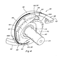
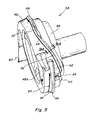
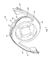
Figure 4 is a perspective view of a body of the inlet section ofFigure 1 ; -
Figure 5 is another perspective view of the body of the rotor ofFigure 1 ; -
Figure 6 is another perspective view of the body of the rotor ofFigure 1 ; -
Figure 7 is another perspective view of the body of the rotor ofFigure 1 ; -
Figure 8 is a sectional view of the body; -
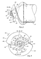
Figure 9 is a fragmentary side view of the rotor inlet section and the front bearing housing and shroud ofFigure 1 , illustrating the cooperative relationship therebetween; -
Figure 9A is an enlarged fragmentary sectional view of the body taken along line 9A-9A ofFigure 5 , illustrating a shoulder thereof; and -
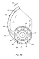
Figure 9B is a rear view of the anti-wind shroud assembly ofFigure 1 . - Referring now to the drawings, in
Figure 1 a self-propelled rotary combine is seen generally at 10. Combine 10 includes afront portion 12 includingfront wheels 14, anoperator cab 16, and an engine (not shown) suitably supported within abody 18. The transfer of power from the engine to various driven components of combine 10 is effected conventionally. - Combine 10 is provided with a crop
harvesting header assembly 20 for cutting and gathering crop materials.Header assembly 20 cuts and directs the crop material into acrop feeder assembly 22 including aconveyor 24.Conveyor 24 carries the crop material upwardly toward arotor assembly 26, which threshes grain from material other than the grain.Rotor assembly 26 is supported in a conventional manner insidebody 18.Rotor assembly 26 includes atubular rotor housing 28 mounted in a front to rear orientation inbody 18.Rotor assembly 26 also includes arotor 30 is mounted inhousing 28 for rotation therein in a predetermined rotational direction about arotational axis 32 throughrotor 30 oriented at an acute angle to horizontal as shown. - Referring also to
Figures 2 and 3 ,rotor 30 is a hollow tube.Rotor 30 ofrotor assembly 26 includes afront shaft 34 projecting concentrically aboutrotational axis 32 from a front infeed orinlet section 36, and a rear threshing section.Front inlet section 36 includes two helical impeller augers 40 extending therearound in a rearward direction from afront center portion 42 to the threshing section.Front inlet section 36 has a conical shape, extending radially outwardly relative toaxis 32 rearwardly from adjacent tofront center portion 42 to the threshing section.Rotor 30 is rotatable inrotor housing 28 in the rotational direction denoted byarrow 44 inFigure 3 . Eachimpeller auger 40 includes a flight having a leadingedge 46 which extends radially outwardly with respect toaxis 32 from a radial outer circumferential edge orperiphery 48 offront center portion 42, and terminating at a radialouter edge 50.Edges 46 are raked or swept back in relation torotational direction 44. Each impeller auger preferably has a helical pitch that increases in the rearward direction along the length thereof, which enablesaugers 40 to aggressively move plant material rearwardly fromfeeder assembly 22 during rotation ofrotor 30, while leadingedges 46 are disposed and rotate in closely spaced relation to ananti-wind shroud assembly 52 which supports and extends around and protects a front bearing housing 54 (Figures 1 ,9 and9B ) carrying a front bearing 56 (Figures 9 and9B ) for supportingshaft 34 and thusinlet section 36 ofrotor 30 for rotation, as will be explained.Front center portion 42 ofinlet section 36 preferably includes a front plate or abody 58 which is also part ofrotor assembly 26, and is preferably welded or otherwise fixedly mounted ontoinlet section 36.Body 58 is preferably of cast or forged construction, andshaft 34 is preferably integrally formed therewith. - Referring also to
Figures 4 ,5 ,6 ,7 and8 ,body 58 includes radialouter periphery 48, and at least one and preferably twofrontwardly extending protuberances 60, that, together, extend at least substantially completely around orenvelope axis 32.Body 58 includes several anti-wind elements, including diametricallyopposed extensions 62 of leadingedges 46 of impeller augers 40 (Figures 2 and 3 ) which extend radially outwardly and at least generally tangentially from radialouter periphery 48 ofbody 58 to connect toedges 46, respectively, and which are also raked or swept back with respect to the rotational direction, to provide a smooth transition of flow of crop material from the extensions to the augers. As shown inFigures 1 and9B ,anti-wind shroud assembly 52 includes ananti-wind wiper 38 having a radialouter surface 82 that extends progressively more radially outwardly in the rotational direction denoted byarrow 44, so as to cooperate withextensions 62 for transitioning the flow of the crop material to the augers.Protuberances 60 preferably form or include a pair ofslots 64 facing frontwardly and extending radially therethrough, eachslot 64 preferably being raked or swept back relative to the rotational direction and being defined in part or bounded by anedge surface 66 of aprotuberance 60 oriented to face in the rotational direction, and which surface 66 is also preferably swept or raked back in the radial outward direction.Protuberances 60 additionally each have a radially outwardly facing outer periphery including an outercircumferential surface 68, and a radially inwardly facing inner periphery including an innercircumferential surface 70 therearound. Preferably, innercircumferential surface 70 has a tapered or frusto-conical shape, which extends convergingly rearwardly towardaxis 32, defining afront center space 72. - Referring more particularly to
Figures 1 and9 ,anti-wind shroud assembly 52 is mounted on abearing support 74 frontwardly ofinlet section 36 ofrotor 30, such that outer peripheralanti-wind wiper 38 andouter surface 82 thereof extend progressively radially outwardly in therotational direction 44 in front of extensions 62 (Figure 1 ),wiper 38 preferably being integrally formed or cast with front bearing housing 54 (Figure 9 ).Front bearing housing 54 contains and carriesconventional bearing 56 for rotatably supportingshaft 34 and thusinlet section 36 and the front end ofrotor 30 for rotation aboutaxis 32. Bearinghousing 54 has a circumferential radialouter surface 76 therearound having a predetermined radial or diametrical extent.Anti-wind shroud assembly 52 has a radialinner surface 78 having a predetermined radial extent which is greater than that ofouter surface 76 of bearinghousing 54, and which is located radially outwardly thereof and extends at least partially therearound, such that at least a partial or generally circular orannular space 80 or path extends around bearinghousing 54 as defined bysurfaces Inner surface 78 is also of at least slightly or marginally greater radial extent than the radial outer periphery ofprotuberances 60, such thatprotuberances 60 are cooperatively receivable inspace 80 for rotation therein. Radialouter surface 82 ofshroud assembly 52 extends partially around bearinghousing 54 and transitions in the direction of rotation ontoanti-wind wiper 38, and a rearwardmostanti-wind wiper edge 84 disposed betweensurfaces anti-wind wiper 38 also, so as to be spaced just marginally frontwardly of radialouter periphery 48 offront center portion 42, and closely in front ofextensions 62, for forcing crop material away from the gap between the anti-wind shroud and the inlet section, to limit infiltration of crop material intospace 80.Anti-wind shroud assembly 52 preferably also include an opening such asopening 86 through the lowest or bottommost portion thereof and communicating or connecting withspace 80, through which crop material can be ejected fromspace 80 by the rotary movement ofprotuberances 60 therein. - As shown variously in
Figures 2, 3 ,4 ,5 ,6 ,7 ,8 ,9 and also 9A and 9B,outer periphery 48 ofbody 58 includes a radially recessedportion 48A adjacent to the radial outer end of eachslot 64, and a radially outwardly projecting lip orshoulder 88 extending circumferentially in the direction opposite the rotational direction and rearwardly, generally from adjacent toportion 48A and a radialouter end portion 90 of each ofslots 64, along and adjacent to a leading portion of eachextension 62, to about the radial outer end thereof. Eachshoulder 88 has a circumferentially extending rearwardly oriented or facingsurface portion 92, which is configured so as to be operable for pushing or conveying the crop material rearwardly away from the radial outer end portion of the slot during the rotation of the body, as generally denoted byarrows 94. This will bring at least some of the crop material into the path ofextensions 62, so as to then be carried or guided thereby rearwardly toimpeller augers 40. - Referring more particularly to
Figures 9 and 9A , it can be observed thatshoulder 88 will rotate in close proximity toanti-wind wiper edge 84 ofshroud assembly 52, so as to cooperate therewith in the rearward pushing of the crop material. The positioning and rotation ofshoulder 88 in close proximity to edge 84 will also serve as an active barrier to passage of crop material frontwardly intospace 80 through the gap or space betweenshoulder 88 andedge 84. At the same time, the lesser radial extent of recessedportions 48A ofperiphery 48 compared to other portions thereof, provides a gap radially inwardly ofextensions 62, for the passage of crop material propelled radially outwardly throughslots 64, to pass radially outwardly and rearwardly fromspace 80. As a result, crop material has substantially no straight-line path to enterspace 80, but a path is provided for the exit or expulsion of crop material therefrom. - Here, it should be noted in reference to inner
circumferential surface 70, that that surface is configured so as to effect the radial outward slinging of crop material thereover by the rotation ofbody 58, and is depicted as having a generally frusto-conical shape although it is contemplated that this surface can have other similar shapes, such as, but not limited to, near frusto-conical, and slightly concave, curved shapes. - It should also be noted that
shoulders 88 follow a generally helical path partially aroundouter periphery 48 and radially outwardly along therespective extensions 62, and can vary in slope or steepness in the axial direction.Shoulders 88 can also vary in radial extent. Thus, as an advantage of the present invention a continuous anti-wind action from the center region ofbody 58, to theaugers 40, is provided. During rotation, crop material withinfront center space 72 will be subjected to a radial outward slinging action bysurface 70. Crop material will also be subject to being forced radially outwardly by contact with edge surface or surfaces 66 of protuberance orprotuberances 60, to a portion orportions 48A ofperiphery 48 so as to be capable of being augered or moved radial outwardly and rearwardly by contact withsurface 92 ofshoulder 88, alongperiphery 48 and anextension 62, to anauger 40. At the same time the rotation ofextensions 62, and shoulders 88, will perform the anti-wind function to keep crop material from winding into the gap betweenbody 58 andanti-wind shroud assembly 52. - It should be noted that
protuberances 60 are shown and discussed herein including two of theslots 64, located at diametrically opposed positions therethrough. It should be recognized and appreciated, however, that just one slot, or more than two slots, located at various positions through the protuberance could be used, depending on factors such as, but not limited to, characteristics of crop material with which the combine is to be used. Also, dimensions ofprotuberance 60, and the sectional shape thereof, can be varied as required or desired for a particular application. - Here, it should also be noted that the terms "rearward" and "rearwardly" are used in respect to
rotor 30, as denoting toward the threshing end thereof, and not with respect to the rearward end of combine 10, as it is recognized thatrotor 30 could be oriented otherwise than front to rearwardly with respect to combine 10, such as in a side to side orientation therein. Additionally, it should be noted that the terms "radial" and "radially" are used with respect toaxis 32. - It will be understood that changes in the details, materials, steps, and arrangements of parts which have been described and illustrated to explain the invention will occur to and may be made by those skilled in the art upon a reading of this disclosure within the scope of the invention as defined by the claims. The foregoing description illustrates the preferred embodiment of the invention; however, concepts, as based upon the description, may be employed in other embodiments without departing from this scope of the invention.
Claims (8)
- A rotor inlet section (36) for a threshing rotor (30) of an agricultural combine (10), comprising a body (58) adapted to be mounted on a front end of a rotor (30) around a frontwardly and rearwardly extending rotational axis (32) therethrough for rotation with the rotor (30) in a predetermined rotational direction (44) about the rotational axis (32), the body (58) comprising:a radial outer circumferential periphery (48); andat least one protuberance (60) extending frontwardly therefrom and at least partially around the rotational axis (32);the outer circumferential periphery (48) disposed radially outwardly and rearwardly of the protuberance (60);the at least one protuberance (60) having a radially inwardly facing inner circumferential surface (70) extending around a front center space (72) andthe at least one protuberance (60) forming at least one frontwardly facing slot (64) extending radially from the front center space (72) to the outer circumferential periphery (48);the at least one slot (64) being raked back in the radial outward direction relative to the rotational direction (44) and defined in part by an edge surface (66) which faces the rotational direction (44) and which is also raked back in the radial outward direction relative to the rotational direction (44) such that when the body (58) is rotated about the rotational axis (32) the edge surface (66) will be operable for pushing crop material from the front center space (72) radially outwardly to the outer circumferential periphery (48),characterised in that the outer circumferential periphery (48) comprises at least one radially outwardly projecting shoulder (88) extending circumferentially and rearwardly from a radial outer end portion (90) of the at least one slot (64), so as to be operable for pushing crop material rearwardly and away from the radial outer end portion (90) of the slot (64) during the rotation of the body (58).
- A rotor inlet section according to claim 1, characterised in that the circumferential periphery (48) comprises a recessed portion (48A) adjacent the radial outer end portion (90) of the at least one slot (64).
- A rotor inlet section according to any of the preceding claims, characterised in that it comprises two of the radially outwardly projecting shoulders (88) in a direction rearwardly from a radial outer end portion (90) of two slots (64) at diametrically opposed locations around the rotational axis (32).
- A rotor inlet section according to any of the preceding claims, characterised in that the front center space (72) comprises an axially centered shaft (34), extending axially therefrom.
- A rotor inlet section according to any of the preceding claims, characterised in that the radial outer periphery (48) extends onto the edge surface facing in the rotational direction (44) of a pair of diametrically opposed extensions (62) extending radially outwardly, each of the extensions (62) being swept back relative to the rotational direction (44).
- A rotor inlet section according to any of the preceding claims, characterised in that the radially inwardly facing inner circumferential surface (70) is generally frusto-conical shaped.
- Apparatus supporting a front end of a rotor (30) for an agricultural combine (10) for rotation in a predetermined rotational direction (44) about a rotational axis (32) extending therethrough, comprising:a rotor inlet section (36) having a front center space (72);a bearing housing (54) supported on the combine (10) and holding a bearing (56) rotatably supporting the rotor inlet section (36), the bearing housing (54) being located at least partially within the front center space (72);an anti-wind shroud (52) extending at least partially around the bearing housing (54) and having a radial inner circumferential surface (78) spaced radially outwardly from a radial outer surface (76) of the bearing housing (54) defining a circumferential space (80) therearound;characterized in that:the rotor inlet section (36) is a rotor inlet section according to any of the preceding claims; andthe protuberance (60) extends frontwardly into the circumferential space (80) in closely spaced relation to the radial outer surface (76) of the bearing housing (54), so as to serve as a barrier to entry of plant material therebetween; and the shoulder (88) is operable to convey the crop material rearwardly through the space (80).
- Method for conveying crop material present in the front center space (72) of a rotor inlet section (36) according to any of the claims 1 to 6, characterised in that during rotation of the body (58) in the rotational direction (44) about the rotational axis (32), the at least one slot (64) will convey crop material present in the front center space (72) radially outwardly to the at least one shoulder (88), and the at least one shoulder (88) will convey the crop material rearwardly along the outer circumferential periphery (48) of the body (58).
Applications Claiming Priority (1)
| Application Number | Priority Date | Filing Date | Title |
|---|---|---|---|
| US11/821,295 US7585212B2 (en) | 2007-06-22 | 2007-06-22 | Combine threshing rotor front bearing and inlet section with improved anti-wind features including a straw ejecting capability |
Publications (1)
| Publication Number | Publication Date |
|---|---|
| EP2005814A1 true EP2005814A1 (en) | 2008-12-24 |
Family
ID=39720726
Family Applications (1)
| Application Number | Title | Priority Date | Filing Date |
|---|---|---|---|
| EP08158532A Withdrawn EP2005814A1 (en) | 2007-06-22 | 2008-06-19 | Combine threshing rotor inlet section |
Country Status (2)
| Country | Link |
|---|---|
| US (1) | US7585212B2 (en) |
| EP (1) | EP2005814A1 (en) |
Families Citing this family (3)
| Publication number | Priority date | Publication date | Assignee | Title |
|---|---|---|---|---|
| US8979623B1 (en) | 2011-11-23 | 2015-03-17 | Ronald J. Kile | Helical auger flight assemblies and thresher formed therewith |
| US9089094B1 (en) * | 2011-11-23 | 2015-07-28 | Ronald J. Kile | Combine thresher with helical auger flights having sacrificial shield and wear plates |
| US9924638B1 (en) | 2011-11-23 | 2018-03-27 | Ronald J. Kile | Helical auger flight assemblies and thresher formed therewith |
Citations (4)
| Publication number | Priority date | Publication date | Assignee | Title |
|---|---|---|---|---|
| US5387153A (en) | 1993-04-06 | 1995-02-07 | Case Corporation | Rotary combine |
| US6296566B1 (en) | 1999-10-05 | 2001-10-02 | Case Corporation | Infeed impeller for a rotary combine |
| US20030092474A1 (en) * | 2001-11-15 | 2003-05-15 | Tanis Dale R. | Combine threshing rotor front bearing and inlet section with anti-wind geometry |
| US20060194627A1 (en) * | 2005-02-28 | 2006-08-31 | Cnh America Llc | Combine threshing rotor front bearing and inlet section with anti-wind features |
Family Cites Families (7)
| Publication number | Priority date | Publication date | Assignee | Title |
|---|---|---|---|---|
| US3537460A (en) | 1968-07-02 | 1970-11-03 | Int Harvester Co | Impeller for axial flow combine |
| US4248248A (en) | 1979-04-06 | 1981-02-03 | Sperry Rand Corporation | Interrupted infeed flight means for combine rotor |
| US4250896A (en) | 1979-06-11 | 1981-02-17 | Sperry Corporation | Anti-wrap means |
| US5145462A (en) | 1991-06-10 | 1992-09-08 | Case Corporation | Infeed assembly for an axial-flow combine |
| US6083102A (en) | 1999-01-14 | 2000-07-04 | Deere & Company | Variable sweep helical infeed element |
| US6719626B2 (en) | 2002-04-26 | 2004-04-13 | Joe Edward Federowich | Axial flow combine and impeller for rotor thereof |
| US6908378B2 (en) | 2003-07-21 | 2005-06-21 | Cnh America Llc | Threshing rotor inlet flight extension |
-
2007
- 2007-06-22 US US11/821,295 patent/US7585212B2/en active Active
-
2008
- 2008-06-19 EP EP08158532A patent/EP2005814A1/en not_active Withdrawn
Patent Citations (5)
| Publication number | Priority date | Publication date | Assignee | Title |
|---|---|---|---|---|
| US5387153A (en) | 1993-04-06 | 1995-02-07 | Case Corporation | Rotary combine |
| US6296566B1 (en) | 1999-10-05 | 2001-10-02 | Case Corporation | Infeed impeller for a rotary combine |
| US20030092474A1 (en) * | 2001-11-15 | 2003-05-15 | Tanis Dale R. | Combine threshing rotor front bearing and inlet section with anti-wind geometry |
| US20060194627A1 (en) * | 2005-02-28 | 2006-08-31 | Cnh America Llc | Combine threshing rotor front bearing and inlet section with anti-wind features |
| US7166025B2 (en) | 2005-02-28 | 2007-01-23 | Cnh America Llc | Combine threshing rotor front bearing and inlet section with anti-wind features |
Also Published As
| Publication number | Publication date |
|---|---|
| US7585212B2 (en) | 2009-09-08 |
| US20080318649A1 (en) | 2008-12-25 |
Similar Documents
| Publication | Publication Date | Title |
|---|---|---|
| US5145462A (en) | Infeed assembly for an axial-flow combine | |
| US5387153A (en) | Rotary combine | |
| US6296566B1 (en) | Infeed impeller for a rotary combine | |
| US4031901A (en) | Concave for an axial flow type combine | |
| US4900290A (en) | Crop delivery system for an axial-flow combine | |
| US6688970B2 (en) | Combine threshing rotor front bearing and inlet section with anti-wind geometry | |
| US4192322A (en) | Axial flow separator with stepped threshing bar rotor | |
| US5257959A (en) | Door assembly for an axial-flow combine | |
| CA2028447C (en) | Rotor assembly for an axial-flow combine | |
| CA1045932A (en) | Helical element rotor - axial flow combine | |
| US7585212B2 (en) | Combine threshing rotor front bearing and inlet section with improved anti-wind features including a straw ejecting capability | |
| EP1872647B1 (en) | Chevron inlet for cross flow fan | |
| CN111867359B (en) | Tangential feed threshing rotor | |
| US6830512B2 (en) | Shroud for the infeed impeller of a rotary combine | |
| US4164947A (en) | Rotor for an axial flow rotary separator | |
| US11147213B2 (en) | Threshing section of a combine | |
| EP1872646A1 (en) | Rotating inlet for cross flow fan. | |
| US5145461A (en) | Door assembly for an axial-flow combine | |
| US6908378B2 (en) | Threshing rotor inlet flight extension | |
| CA2511713C (en) | Transverse conveying screw for a harvesting front attachment | |
| US7166025B2 (en) | Combine threshing rotor front bearing and inlet section with anti-wind features | |
| US7223167B2 (en) | Anti-wind wiper with adjustable extension | |
| EP4132261B1 (en) | Threshing system and chopper for combine harvester |
Legal Events
| Date | Code | Title | Description |
|---|---|---|---|
| PUAI | Public reference made under article 153(3) epc to a published international application that has entered the european phase |
Free format text: ORIGINAL CODE: 0009012 |
|
| AK | Designated contracting states |
Kind code of ref document: A1 Designated state(s): AT BE BG CH CY CZ DE DK EE ES FI FR GB GR HR HU IE IS IT LI LT LU LV MC MT NL NO PL PT RO SE SI SK TR |
|
| AX | Request for extension of the european patent |
Extension state: AL BA MK RS |
|
| 17P | Request for examination filed |
Effective date: 20090624 |
|
| 17Q | First examination report despatched |
Effective date: 20090722 |
|
| AKX | Designation fees paid |
Designated state(s): AT BE BG CH CY CZ DE DK EE ES FI FR GB GR HR HU IE IS IT LI LT LU LV MC MT NL NO PL PT RO SE SI SK TR |
|
| STAA | Information on the status of an ep patent application or granted ep patent |
Free format text: STATUS: THE APPLICATION IS DEEMED TO BE WITHDRAWN |
|
| 18D | Application deemed to be withdrawn |
Effective date: 20100202 |