EP2004310B1 - Method for removing sulfur from gaseous fuels using a self regenerating desulfurizer - Google Patents
Method for removing sulfur from gaseous fuels using a self regenerating desulfurizer Download PDFInfo
- Publication number
- EP2004310B1 EP2004310B1 EP06845059A EP06845059A EP2004310B1 EP 2004310 B1 EP2004310 B1 EP 2004310B1 EP 06845059 A EP06845059 A EP 06845059A EP 06845059 A EP06845059 A EP 06845059A EP 2004310 B1 EP2004310 B1 EP 2004310B1
- Authority
- EP
- European Patent Office
- Prior art keywords
- flow
- layer
- sulfur
- pyrophoric
- desulfurizing
- Prior art date
- Legal status (The legal status is an assumption and is not a legal conclusion. Google has not performed a legal analysis and makes no representation as to the accuracy of the status listed.)
- Not-in-force
Links
- NINIDFKCEFEMDL-UHFFFAOYSA-N Sulfur Chemical compound [S] NINIDFKCEFEMDL-UHFFFAOYSA-N 0.000 title claims description 70
- 239000011593 sulfur Substances 0.000 title claims description 69
- 229910052717 sulfur Inorganic materials 0.000 title claims description 69
- 239000000446 fuel Substances 0.000 title claims description 52
- 238000000034 method Methods 0.000 title claims description 28
- 230000001172 regenerating effect Effects 0.000 title claims description 9
- 230000003009 desulfurizing effect Effects 0.000 claims description 40
- 239000002355 dual-layer Substances 0.000 claims description 27
- 238000010926 purge Methods 0.000 claims description 21
- 230000001590 oxidative effect Effects 0.000 claims description 13
- PXHVJJICTQNCMI-UHFFFAOYSA-N Nickel Chemical compound [Ni] PXHVJJICTQNCMI-UHFFFAOYSA-N 0.000 claims description 8
- 239000010457 zeolite Substances 0.000 claims description 8
- 229910021536 Zeolite Inorganic materials 0.000 claims description 7
- HNPSIPDUKPIQMN-UHFFFAOYSA-N dioxosilane;oxo(oxoalumanyloxy)alumane Chemical compound O=[Si]=O.O=[Al]O[Al]=O HNPSIPDUKPIQMN-UHFFFAOYSA-N 0.000 claims description 7
- XEEYBQQBJWHFJM-UHFFFAOYSA-N Iron Chemical compound [Fe] XEEYBQQBJWHFJM-UHFFFAOYSA-N 0.000 claims description 4
- BQCADISMDOOEFD-UHFFFAOYSA-N Silver Chemical compound [Ag] BQCADISMDOOEFD-UHFFFAOYSA-N 0.000 claims description 4
- 229910052759 nickel Inorganic materials 0.000 claims description 4
- 229910052709 silver Inorganic materials 0.000 claims description 4
- 239000004332 silver Substances 0.000 claims description 4
- MUBKMWFYVHYZAI-UHFFFAOYSA-N [Al].[Cu].[Zn] Chemical compound [Al].[Cu].[Zn] MUBKMWFYVHYZAI-UHFFFAOYSA-N 0.000 claims description 3
- 229910052742 iron Inorganic materials 0.000 claims 1
- 229910052751 metal Inorganic materials 0.000 claims 1
- 239000002184 metal Substances 0.000 claims 1
- 239000010410 layer Substances 0.000 description 79
- 239000000463 material Substances 0.000 description 30
- VNWKTOKETHGBQD-UHFFFAOYSA-N methane Chemical compound C VNWKTOKETHGBQD-UHFFFAOYSA-N 0.000 description 14
- 230000008929 regeneration Effects 0.000 description 13
- 238000011069 regeneration method Methods 0.000 description 13
- 239000007789 gas Substances 0.000 description 9
- 239000003463 adsorbent Substances 0.000 description 6
- 239000003054 catalyst Substances 0.000 description 6
- 239000003345 natural gas Substances 0.000 description 6
- 238000002407 reforming Methods 0.000 description 6
- 239000006096 absorbing agent Substances 0.000 description 5
- 239000002250 absorbent Substances 0.000 description 4
- 230000002745 absorbent Effects 0.000 description 4
- 238000005381 potential energy Methods 0.000 description 4
- 238000001179 sorption measurement Methods 0.000 description 4
- 238000010438 heat treatment Methods 0.000 description 3
- OKTJSMMVPCPJKN-UHFFFAOYSA-N Carbon Chemical compound [C] OKTJSMMVPCPJKN-UHFFFAOYSA-N 0.000 description 2
- RWSOTUBLDIXVET-UHFFFAOYSA-N Dihydrogen sulfide Chemical compound S RWSOTUBLDIXVET-UHFFFAOYSA-N 0.000 description 2
- 238000007664 blowing Methods 0.000 description 2
- 150000001768 cations Chemical group 0.000 description 2
- 238000006243 chemical reaction Methods 0.000 description 2
- 239000000356 contaminant Substances 0.000 description 2
- 230000008030 elimination Effects 0.000 description 2
- 238000003379 elimination reaction Methods 0.000 description 2
- 229930195733 hydrocarbon Natural products 0.000 description 2
- 150000002430 hydrocarbons Chemical class 0.000 description 2
- 229910000037 hydrogen sulfide Inorganic materials 0.000 description 2
- 238000006722 reduction reaction Methods 0.000 description 2
- 150000003464 sulfur compounds Chemical class 0.000 description 2
- 239000004215 Carbon black (E152) Substances 0.000 description 1
- BVKZGUZCCUSVTD-UHFFFAOYSA-L Carbonate Chemical compound [O-]C([O-])=O BVKZGUZCCUSVTD-UHFFFAOYSA-L 0.000 description 1
- RYGMFSIKBFXOCR-UHFFFAOYSA-N Copper Chemical group [Cu] RYGMFSIKBFXOCR-UHFFFAOYSA-N 0.000 description 1
- 238000005411 Van der Waals force Methods 0.000 description 1
- 230000002411 adverse Effects 0.000 description 1
- 238000003915 air pollution Methods 0.000 description 1
- PNEYBMLMFCGWSK-UHFFFAOYSA-N aluminium oxide Inorganic materials [O-2].[O-2].[O-2].[Al+3].[Al+3] PNEYBMLMFCGWSK-UHFFFAOYSA-N 0.000 description 1
- 239000003638 chemical reducing agent Substances 0.000 description 1
- 229910052802 copper Inorganic materials 0.000 description 1
- 239000010949 copper Substances 0.000 description 1
- 238000006477 desulfuration reaction Methods 0.000 description 1
- 230000023556 desulfurization Effects 0.000 description 1
- 230000009977 dual effect Effects 0.000 description 1
- 238000000605 extraction Methods 0.000 description 1
- 239000003205 fragrance Substances 0.000 description 1
- 238000011065 in-situ storage Methods 0.000 description 1
- 230000002452 interceptive effect Effects 0.000 description 1
- 238000012423 maintenance Methods 0.000 description 1
- 229910052976 metal sulfide Inorganic materials 0.000 description 1
- 125000001741 organic sulfur group Chemical group 0.000 description 1
- 238000010248 power generation Methods 0.000 description 1
- 239000007787 solid Substances 0.000 description 1
- 239000000126 substance Substances 0.000 description 1
- 239000000758 substrate Substances 0.000 description 1
- 238000013022 venting Methods 0.000 description 1
- XLYOFNOQVPJJNP-UHFFFAOYSA-N water Chemical compound O XLYOFNOQVPJJNP-UHFFFAOYSA-N 0.000 description 1
Images

Classifications
-
- B—PERFORMING OPERATIONS; TRANSPORTING
- B01—PHYSICAL OR CHEMICAL PROCESSES OR APPARATUS IN GENERAL
- B01D—SEPARATION
- B01D53/00—Separation of gases or vapours; Recovering vapours of volatile solvents from gases; Chemical or biological purification of waste gases, e.g. engine exhaust gases, smoke, fumes, flue gases, aerosols
- B01D53/34—Chemical or biological purification of waste gases
- B01D53/46—Removing components of defined structure
- B01D53/48—Sulfur compounds
- B01D53/50—Sulfur oxides
- B01D53/508—Sulfur oxides by treating the gases with solids
-
- B—PERFORMING OPERATIONS; TRANSPORTING
- B01—PHYSICAL OR CHEMICAL PROCESSES OR APPARATUS IN GENERAL
- B01D—SEPARATION
- B01D53/00—Separation of gases or vapours; Recovering vapours of volatile solvents from gases; Chemical or biological purification of waste gases, e.g. engine exhaust gases, smoke, fumes, flue gases, aerosols
- B01D53/34—Chemical or biological purification of waste gases
- B01D53/46—Removing components of defined structure
- B01D53/48—Sulfur compounds
-
- B—PERFORMING OPERATIONS; TRANSPORTING
- B01—PHYSICAL OR CHEMICAL PROCESSES OR APPARATUS IN GENERAL
- B01D—SEPARATION
- B01D53/00—Separation of gases or vapours; Recovering vapours of volatile solvents from gases; Chemical or biological purification of waste gases, e.g. engine exhaust gases, smoke, fumes, flue gases, aerosols
- B01D53/02—Separation of gases or vapours; Recovering vapours of volatile solvents from gases; Chemical or biological purification of waste gases, e.g. engine exhaust gases, smoke, fumes, flue gases, aerosols by adsorption, e.g. preparative gas chromatography
-
- B—PERFORMING OPERATIONS; TRANSPORTING
- B01—PHYSICAL OR CHEMICAL PROCESSES OR APPARATUS IN GENERAL
- B01D—SEPARATION
- B01D53/00—Separation of gases or vapours; Recovering vapours of volatile solvents from gases; Chemical or biological purification of waste gases, e.g. engine exhaust gases, smoke, fumes, flue gases, aerosols
- B01D53/02—Separation of gases or vapours; Recovering vapours of volatile solvents from gases; Chemical or biological purification of waste gases, e.g. engine exhaust gases, smoke, fumes, flue gases, aerosols by adsorption, e.g. preparative gas chromatography
- B01D53/04—Separation of gases or vapours; Recovering vapours of volatile solvents from gases; Chemical or biological purification of waste gases, e.g. engine exhaust gases, smoke, fumes, flue gases, aerosols by adsorption, e.g. preparative gas chromatography with stationary adsorbents
-
- C—CHEMISTRY; METALLURGY
- C10—PETROLEUM, GAS OR COKE INDUSTRIES; TECHNICAL GASES CONTAINING CARBON MONOXIDE; FUELS; LUBRICANTS; PEAT
- C10G—CRACKING HYDROCARBON OILS; PRODUCTION OF LIQUID HYDROCARBON MIXTURES, e.g. BY DESTRUCTIVE HYDROGENATION, OLIGOMERISATION, POLYMERISATION; RECOVERY OF HYDROCARBON OILS FROM OIL-SHALE, OIL-SAND, OR GASES; REFINING MIXTURES MAINLY CONSISTING OF HYDROCARBONS; REFORMING OF NAPHTHA; MINERAL WAXES
- C10G25/00—Refining of hydrocarbon oils in the absence of hydrogen, with solid sorbents
- C10G25/02—Refining of hydrocarbon oils in the absence of hydrogen, with solid sorbents with ion-exchange material
- C10G25/03—Refining of hydrocarbon oils in the absence of hydrogen, with solid sorbents with ion-exchange material with crystalline alumino-silicates, e.g. molecular sieves
- C10G25/05—Removal of non-hydrocarbon compounds, e.g. sulfur compounds
-
- C—CHEMISTRY; METALLURGY
- C10—PETROLEUM, GAS OR COKE INDUSTRIES; TECHNICAL GASES CONTAINING CARBON MONOXIDE; FUELS; LUBRICANTS; PEAT
- C10G—CRACKING HYDROCARBON OILS; PRODUCTION OF LIQUID HYDROCARBON MIXTURES, e.g. BY DESTRUCTIVE HYDROGENATION, OLIGOMERISATION, POLYMERISATION; RECOVERY OF HYDROCARBON OILS FROM OIL-SHALE, OIL-SAND, OR GASES; REFINING MIXTURES MAINLY CONSISTING OF HYDROCARBONS; REFORMING OF NAPHTHA; MINERAL WAXES
- C10G25/00—Refining of hydrocarbon oils in the absence of hydrogen, with solid sorbents
- C10G25/12—Recovery of used adsorbent
-
- C—CHEMISTRY; METALLURGY
- C10—PETROLEUM, GAS OR COKE INDUSTRIES; TECHNICAL GASES CONTAINING CARBON MONOXIDE; FUELS; LUBRICANTS; PEAT
- C10G—CRACKING HYDROCARBON OILS; PRODUCTION OF LIQUID HYDROCARBON MIXTURES, e.g. BY DESTRUCTIVE HYDROGENATION, OLIGOMERISATION, POLYMERISATION; RECOVERY OF HYDROCARBON OILS FROM OIL-SHALE, OIL-SAND, OR GASES; REFINING MIXTURES MAINLY CONSISTING OF HYDROCARBONS; REFORMING OF NAPHTHA; MINERAL WAXES
- C10G31/00—Refining of hydrocarbon oils, in the absence of hydrogen, by methods not otherwise provided for
- C10G31/09—Refining of hydrocarbon oils, in the absence of hydrogen, by methods not otherwise provided for by filtration
-
- B—PERFORMING OPERATIONS; TRANSPORTING
- B01—PHYSICAL OR CHEMICAL PROCESSES OR APPARATUS IN GENERAL
- B01D—SEPARATION
- B01D2253/00—Adsorbents used in seperation treatment of gases and vapours
- B01D2253/10—Inorganic adsorbents
- B01D2253/106—Silica or silicates
- B01D2253/108—Zeolites
-
- B—PERFORMING OPERATIONS; TRANSPORTING
- B01—PHYSICAL OR CHEMICAL PROCESSES OR APPARATUS IN GENERAL
- B01D—SEPARATION
- B01D2259/00—Type of treatment
- B01D2259/40—Further details for adsorption processes and devices
- B01D2259/40083—Regeneration of adsorbents in processes other than pressure or temperature swing adsorption
- B01D2259/40088—Regeneration of adsorbents in processes other than pressure or temperature swing adsorption by heating
-
- B—PERFORMING OPERATIONS; TRANSPORTING
- B01—PHYSICAL OR CHEMICAL PROCESSES OR APPARATUS IN GENERAL
- B01D—SEPARATION
- B01D2259/00—Type of treatment
- B01D2259/40—Further details for adsorption processes and devices
- B01D2259/402—Further details for adsorption processes and devices using two beds
-
- B—PERFORMING OPERATIONS; TRANSPORTING
- B01—PHYSICAL OR CHEMICAL PROCESSES OR APPARATUS IN GENERAL
- B01D—SEPARATION
- B01D2259/00—Type of treatment
- B01D2259/40—Further details for adsorption processes and devices
- B01D2259/414—Further details for adsorption processes and devices using different types of adsorbents
- B01D2259/4141—Further details for adsorption processes and devices using different types of adsorbents within a single bed
- B01D2259/4145—Further details for adsorption processes and devices using different types of adsorbents within a single bed arranged in series
- B01D2259/4146—Contiguous multilayered adsorbents
-
- C—CHEMISTRY; METALLURGY
- C10—PETROLEUM, GAS OR COKE INDUSTRIES; TECHNICAL GASES CONTAINING CARBON MONOXIDE; FUELS; LUBRICANTS; PEAT
- C10G—CRACKING HYDROCARBON OILS; PRODUCTION OF LIQUID HYDROCARBON MIXTURES, e.g. BY DESTRUCTIVE HYDROGENATION, OLIGOMERISATION, POLYMERISATION; RECOVERY OF HYDROCARBON OILS FROM OIL-SHALE, OIL-SAND, OR GASES; REFINING MIXTURES MAINLY CONSISTING OF HYDROCARBONS; REFORMING OF NAPHTHA; MINERAL WAXES
- C10G2300/00—Aspects relating to hydrocarbon processing covered by groups C10G1/00 - C10G99/00
- C10G2300/20—Characteristics of the feedstock or the products
- C10G2300/201—Impurities
- C10G2300/202—Heteroatoms content, i.e. S, N, O, P
Definitions
- the field of the invention relates to fuel desulfurizers, and more particularly to a double layer bed system for the removal of sulfur from gaseous fuels.
- Pipeline natural gas is the primary fuel of choice for distributed fuel cell-based power generation systems because of its abundant supply and well-developed infrastructure.
- a fuel processing system at the unit inlet to reform the methane and higher hydrocarbons in natural gas, both solid oxide fuel cells and molten carbonate fuel cells will convert chemical energy directly into electrical energy for power distribution.
- processing of natural gas to remove sulfur is usually carried out close to the point of extraction, the processing leaves residual hydrogen sulfide as a contaminant at low concentration (e.g. 1-2 mg/m 3 ).
- pipeline natural gas usually contains other organic sulfur species that have been intentionally added as odorants.
- the fuel reforming process requires heat, water vapor and a catalyst that enhances the chemical reaction rate.
- the most commonly used catalysts are nickel based.
- the catalyst At the natural gas reforming temperature, the catalyst is highly susceptible to conversion into a metal sulfide if sulfur is present in the gas feed. This inactivates the catalyst and stops the reforming process. Therefore it is necessary to remove the sulfur from the gas flow to permit the desired fuel reforming to occur.
- sulfur that makes it through the reforming process will contribute to air pollution.
- the present invention provides for a new type of desulfurizer for gaseous fuels.
- Sulfur needs to be removed from gaseous fuels. It is a natural contaminant found in natural gas, and can also be an added containment as part of the odorization process.
- sulfur is also very damaging to catalysts and other machinery parts, and causes reduction in performance. Process to remove the sulfur, however, requires maintenance since the desulfurizing capacity becomes spent.
- the invention uses a double layer system.
- the first layer uses a regenerable sulfur absorber, such as zeolite.
- the second layer is a pyrophoric material.
- the desulfurizer is isolated and removed from service.
- air is blown backwards through the desulfurizer.
- air passes over the pyrophoric material, it is heated.
- the heated air then provides the energy for physically adsorbed sulfur compounds to be released from the adsorbing surfaces and removes the sulfur from the sulfur absorber, regenerating it.
- the fuel stream reduces the pyrophoric material, in tum regenerating it.
- a regenerable sulfur remover that comprises a gaseous flow, a first layer in line with the gaseous flow, and a second layer in line with the first layer.
- the first layer comprises a physical absorber of sulfur; the second layer comprises a pyrophoric material capable of being reduced by the gaseous flow.
- a blower blows air first over the second layer, the air flow is heated by passing over the second layer, and then over the first layer.
- Air refers to any oxidizing gas. The heated air flow removes sulfur from the first layer, and the air flow is exhausted after removing sulfur from the first layer. A purge clears the first layer and the second layer of the air flow.
- the present invention provides for a regenerable sulfur remover for gaseous fuel flows that comprises a gaseous fuel flow, one or more pyrophoric layers, one or more desulfurizing layers, an air flow, an exhaust, and a purge.
- the exhaust and the purge may be the same line.
- the gaseous fuel flow passes over the pyrophoric material, transferring a portion of potential energy in the gaseous fuel flow to the pyrophoric layer.
- the gaseous fuel flow passes over the desulfurizing layer, sulfur is removed from the gaseous fuel flow, and to regenerate the desulfurizing layer, the air flow is passed over the pyrophoric layer heating the air flow and producing a heated air flow.
- the heated air flow is passed over the desulfurizing layer, removing sulfur from the desulfurizing layer.
- the heated air flow is exhausted after removing sulfur from the desulfurizing layer, and the purge purges the air flow and the heated air flow from the regenerable sulfur remover.
- the present invention provides for a method for removing sulfur from a gaseous fuel flow that comprises passing a gaseous fuel flow over one or more dual layer bed.
- the one or more dual layer comprises a desulfurizing portion and a pyrophoric portion, the desulfurizing portion removes sulfur from the gaseous fuel flow, and the pyrophoric portion stores a portion of energy from the gaseous fuel flow. Then determining a time to regenerate the desulfurizing portion of the one or more dual layer bed, and passing an air flow first over a substantial portion of the pyrophoric portion of the one or more dual layer bed, then over the desulfurizing portion.
- the air flow is heated by the pyrophoric portion, and the heated air flow removes sulfur from the desulfurizing portion to produce a sulfurous air flow. Then exhausting the sulfurous air flow, and purging the one or more dual layer bed of the air flow.
- the desulfurizing portion is a zeolite.
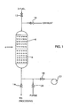
- Figure 1 illustrates an embodiment of the present invention with the regeneration air blowing in an opposite direction to the fuel flow.
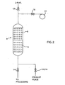
- Figure 2 illustrates an embodiment of the present invention with the regeneration blowing in the same direction as the fuel flow.
- the pyrophoric layer is on top of the adsorbing layer.
- FIG. 3 illustrates two dual layer desulfurizer beds being operated in parallel according to one embodiment of the present invention.
- the present invention provides for a regenerable two layer desulfurizer capable of removing even small amounts of sulfur from a gaseous fuel flow. Even small amounts of sulfur in a gaseous fuel flow can ruin sensitive catalysts and stop fuel reforming.
- the prior art sulfur removers generally require replacement and disposal of the adsorbing bed layer after it has become spent. If they are designed for in situ regeneration, an external source of regenerating heat is needed. In many cases this regenerating heat is provided in the form of steam.
- An advantage with the present invention is the elimination of the need for external equipment to remove and replace the spent bed or elimination of the external regeneration equipment and also the energy needed to supply heat.
- the time taken to replace or regenerate sulfur removers of the prior art leads to down time and added costs.
- a gaseous fuel can have most or all of its sulfur removed, with down times being few and limited.
- the present invention passes a fuel flow past a first layer composed of a regenerable sulfur adsorbing material that absorbs the sulfur, and then past a second layer of a pyrophoric material that can use some (small) amount of the heat in the flowing gas for a chemical reduction to store as potential energy.
- a first layer composed of a regenerable sulfur adsorbing material that absorbs the sulfur
- a second layer of a pyrophoric material that can use some (small) amount of the heat in the flowing gas for a chemical reduction to store as potential energy.
- the arrangements of these beds may be varied.
- an air flow is first passed over the pyrophoric material, which releases the potential energy and heats the air flow.
- the heated air flow then passes over the desulfurizing layer, heating it to sufficient temperatures so that the bound sulfur is then released into the air stream.
- This stream is vented until the desulfurizing layer is regenerated and/or the pyrophoric layer is exhausted.
- a purge is then passed through the system, venting the remaining air.
- the sulfur adsorbent is a Zeolite material.
- Cation exchanged Zeolite-Y removes sulfur compounds by the process of physical adsorption.
- the sulfur containing molecules are not destroyed by the adsorption; they are attracted to the cation sites in the Zeolite by van der Waals forces, which are not as strong as covalent bonds and can be easily broken; therefore the adsorbent works better at room temperature or below.
- the adsorption can also work in both oxidizing and reducing environments.
- Zeolite-Y materials such as silver and copper exchanged Zeolite-Y have about 100-150 times the sulfur absorbing from hydrocarbon fuels as compared with prior art activated carbon. As a result of this, standard sized beds can be produced that will continuously absorb sulfur for months and even years.
- heat may be applied. Passing a gas at about 300 °C over the Zeolite will remove the sulfur and regenerate the adsorbent. The sulfur will then be carried away in the gas flow. This heat is supplied by the pyrophoric material of the second layer.
- the pyrophoric material is inert in regards to the normal operation of the gaseous fuel flow. But when oxidizing gas is passed over the pyrophoric material, such as air, it releases energy in the form of heat. Ideally the heat is released at a steady rate, bringing the air to temperatures that will release the sulfur from the absorbent, but not so high as to damage the absorbent material. For example, temperatures in the range of 300 °C are sufficient.
- the pyrophoric material may be made of materials known in the art, such as reduced iron, nickel, aluminum, copper, zinc and silver typically dispersed unto an inert, temperature resistant substrate such as alumina.
- the pyrophoric material is referred to as the material of the layer. In a particular embodiment, it is in fact a second layer, immediately after the first layer of absorbent material. In this embodiment, the air blown over the pyrophoric material will have to pass in an opposite direction to gas flow. However, in other embodiments, the second layer of pyrophoric material may be positioned before the first layer of adsorbent material. In such an embodiment, the regenerating air flow will pass in the same direction as the gaseous fuel flow.
- the second layer in some embodiments may even be combined with the first layer. If the two layers are homogeneously combined, then the adsorbent towards the start of the layer during the regeneration process may not receive enough heat to properly regenerate. Therefore, if the two layers are combined, a gradient combination will be preferred, where the pyrophoric material is heavier towards the end that begins the regeneration process.
- Fig. 1 illustrates one embodiment of the present invention.
- fuel 2 is passed into the system and encounters the dual layer bed 4 .
- the fuel first passes over the desulfurizing layer 6 followed by the pyrophoric layer 8 , and is then processed.
- the standard operating valves 12 , 14 are open and the regenerating valves 16 , 18 and purge valve 20 are closed.
- the regeneration valves 16 , 18 are opened and the standard operating valves 12 , 14 are closed.
- a blower 22 then pumps air backwards through the system.
- the air is heated to sufficiently high temperatures so that the sulfur bonded to the desulfurizing layer is removed and exhausted.
- the regenerating valves are closed and the fuel valve 12 and the purge valve 20 is opened so that the system can be purged of air before standard operation proceeds.
- the system may be purged in a variety of ways, such as fuel being added from the blower 22 , in which case a separate purge valve would not be needed.
- Fig. 2 illustrates an example of the layers being stacked in opposite sequence.
- the fuel 2 first passes through the pyrophoric material 8 and then the desulfurizing layer 6 .
- the blower 22 this time enters the top of the dual layer 4 and is exhausted at the bottom.
- the purge and exhaust is the same, so the purge/exhaust valve 16 , 20 is used for both processes.
- the dual layers have distinctly defined regions. This, however, does not necessarily have to be the case.
- the layers may be somewhat mixed, as long as there is a gradient that greatly favors the pyrophoric material at the start of the regeneration. Without a substantial amount of pyrophoric material at the start of the regeneration, the air will not be heated to sufficient temperature to regenerate the desulfurizing material. Conversely, the two beds may actually be physically separated by some distance, although this may adversely affect keeping the air flow at high temperatures.
- FIG. 3 illustrates a simple example of two dual layer beds being run in parallel.
- one dual layer bed 4 may be isolated from the other for regeneration, without interfering with the desulfurization of the other dual layer bed.
- the present invention provides for a regenerable sulfur remover that comprises a gaseous flow, a first layer in line with the gaseous flow, and a second layer in line with the first layer.
- the first layer comprises a physical absorber of sulfur; the second layer comprises a pyrophoric material capable of being reduced by the gaseous flow.
- a blower blows air first over the second layer, the air flow is heated by passing over the second layer, and then over the first layer.
- Air refers to any oxidizing gas.
- the heated air flow removes sulfur from the first layer, and the air flow is exhausted after removing sulfur from the first layer.
- a purge clears the first layer and the second layer of the air flow.
- the gaseous flow is a fuel.
- the physical absorber is zeolite or some other sulfur absorbent relying upon the process of physical adsorption to remove sulfur.
- the first layer is contacted by the gaseous flow before the second layer.
- the first layer is contacted by the gaseous flow after the second layer, and the air flow enters the regenerable sulfur remover on the same side as the gaseous flow.
- the exhaust and the purge are the same line.
- one or more additional regenerable sulfur remover is run in parallel with the regenerable sulfur remover.
- the one or more additional regenerable sulfur remover may be regenerated while the regenerable sulfur remover continues to remove sulfur from the gaseous flow.
- the pyrophoric material is chosen from the group consisting of reduced iron, nickel, aluminum, copper, zinc and silver.
- the air flow being heated to about 300 °C.
- the present invention provides for a regenerable sulfur remover for gaseous fuel flows that comprises a gaseous fuel flow, one or more pyrophoric layers, one or more desulfurizing layers, an air flow, an exhaust, and a purge.
- the exhaust and the purge may be the same line.
- the gaseous fuel flow passes over the pyrophoric material, transferring a portion of potential energy in the gaseous fuel flow to the pyrophoric layer.
- the gaseous fuel flow passes over the desulfurizing layer, sulfur is removed from the gaseous fuel flow, and to regenerate the desulfurizing layer, the air flow is passed over the pyrophoric layer heating the air flow and producing a heated air flow.
- the heated air flow is passed over the desulfurizing layer, removing sulfur from the desulfurizing layer.
- the heated air flow is exhausted after removing sulfur from the desulfurizing layer, and the purge purges the air flow and the heated air flow from the regenerable sulfur remover.
- the present invention provides for a method for removing sulfur from a gaseous fuel flow that comprises passing a gaseous fuel flow over one or more dual layer bed.
- the one or more dual layer comprises a desulfurizing portion and a pyrophoric portion, the desulfurizing portion removes sulfur from the gaseous fuel flow, and the pyrophoric portion stores a portion of energy from the gaseous fuel flow. Then determining a time to regenerate the desulfurizing portion of the one or more dual layer bed, and passing an air flow first over a substantial portion of the pyrophoric portion of the one or more dual layer bed, then over the desulfurizing portion.
- the air flow is heated by the pyrophoric portion, and the heated air flow removes sulfur form the desulfurizing portion to produce a sulfurous air flow. Then exhausting the sulfurous air flow, and purging the one or more dual layer bed of the air flow.
- the desulfurizing portion is a zeolite.
Landscapes
- Chemical & Material Sciences (AREA)
- Oil, Petroleum & Natural Gas (AREA)
- Engineering & Computer Science (AREA)
- General Chemical & Material Sciences (AREA)
- Chemical Kinetics & Catalysis (AREA)
- Analytical Chemistry (AREA)
- Organic Chemistry (AREA)
- Biomedical Technology (AREA)
- Environmental & Geological Engineering (AREA)
- Health & Medical Sciences (AREA)
- Crystallography & Structural Chemistry (AREA)
- Solid-Sorbent Or Filter-Aiding Compositions (AREA)
- Separation Of Gases By Adsorption (AREA)
Description
- The field of the invention relates to fuel desulfurizers, and more particularly to a double layer bed system for the removal of sulfur from gaseous fuels.
- Pipeline natural gas is the primary fuel of choice for distributed fuel cell-based power generation systems because of its abundant supply and well-developed infrastructure. By using a fuel processing system at the unit inlet to reform the methane and higher hydrocarbons in natural gas, both solid oxide fuel cells and molten carbonate fuel cells will convert chemical energy directly into electrical energy for power distribution. Although processing of natural gas to remove sulfur is usually carried out close to the point of extraction, the processing leaves residual hydrogen sulfide as a contaminant at low concentration (e.g. 1-2 mg/m3). In addition to the naturally occurring hydrogen sulfide, pipeline natural gas usually contains other organic sulfur species that have been intentionally added as odorants.
- The fuel reforming process requires heat, water vapor and a catalyst that enhances the chemical reaction rate. The most commonly used catalysts are nickel based. At the natural gas reforming temperature, the catalyst is highly susceptible to conversion into a metal sulfide if sulfur is present in the gas feed. This inactivates the catalyst and stops the reforming process. Therefore it is necessary to remove the sulfur from the gas flow to permit the desired fuel reforming to occur. In addition, sulfur that makes it through the reforming process will contribute to air pollution.
- Advancement in the art of purifying materials has been made, such as with
Kataoka, US 6,828,141 . However, this process is not regenerable, and does not have the specificity to sulfur as is needed. What is needed is a regenerable method and apparatus that can remove low levels of sulfur from a gaseous fuel flow. - Other difficulties with the prior art also exist, some of which will be apparent upon further reading.
- With the foregoing in mind, methods and apparatuses consistent with the present invention, which inter alia facilitates the removal of sulfur from gaseous fuels. The present invention provides for a new type of desulfurizer for gaseous fuels. Sulfur needs to be removed from gaseous fuels. It is a natural contaminant found in natural gas, and can also be an added containment as part of the odorization process. However, sulfur is also very damaging to catalysts and other machinery parts, and causes reduction in performance. Process to remove the sulfur, however, requires maintenance since the desulfurizing capacity becomes spent.
- The invention uses a double layer system. The first layer uses a regenerable sulfur absorber, such as zeolite. The second layer is a pyrophoric material. When the first layer adsorbs its capacity of sulfur, the desulfurizer is isolated and removed from service. To restore the sulfur adsorbing capacity of the adsorbent, air is blown backwards through the desulfurizer. As air passes over the pyrophoric material, it is heated. The heated air then provides the energy for physically adsorbed sulfur compounds to be released from the adsorbing surfaces and removes the sulfur from the sulfur absorber, regenerating it. When the system is in normal operation, the fuel stream reduces the pyrophoric material, in tum regenerating it.
- These and other objects, features, and advantages in accordance with the present invention are provided particular embodiments by a regenerable sulfur remover that comprises a gaseous flow, a first layer in line with the gaseous flow, and a second layer in line with the first layer. The first layer comprises a physical absorber of sulfur; the second layer comprises a pyrophoric material capable of being reduced by the gaseous flow. During regeneration a blower blows air first over the second layer, the air flow is heated by passing over the second layer, and then over the first layer. Air, as used herein, refers to any oxidizing gas. The heated air flow removes sulfur from the first layer, and the air flow is exhausted after removing sulfur from the first layer. A purge clears the first layer and the second layer of the air flow.
- In another embodiment the present invention provides for a regenerable sulfur remover for gaseous fuel flows that comprises a gaseous fuel flow, one or more pyrophoric layers, one or more desulfurizing layers, an air flow, an exhaust, and a purge. The exhaust and the purge may be the same line. The gaseous fuel flow passes over the pyrophoric material, transferring a portion of potential energy in the gaseous fuel flow to the pyrophoric layer. The gaseous fuel flow passes over the desulfurizing layer, sulfur is removed from the gaseous fuel flow, and to regenerate the desulfurizing layer, the air flow is passed over the pyrophoric layer heating the air flow and producing a heated air flow. The heated air flow is passed over the desulfurizing layer, removing sulfur from the desulfurizing layer. The heated air flow is exhausted after removing sulfur from the desulfurizing layer, and the purge purges the air flow and the heated air flow from the regenerable sulfur remover.
- In still another embodiment the present invention provides for a method for removing sulfur from a gaseous fuel flow that comprises passing a gaseous fuel flow over one or more dual layer bed. The one or more dual layer comprises a desulfurizing portion and a pyrophoric portion, the desulfurizing portion removes sulfur from the gaseous fuel flow, and the pyrophoric portion stores a portion of energy from the gaseous fuel flow. Then determining a time to regenerate the desulfurizing portion of the one or more dual layer bed, and passing an air flow first over a substantial portion of the pyrophoric portion of the one or more dual layer bed, then over the desulfurizing portion. The air flow is heated by the pyrophoric portion, and the heated air flow removes sulfur from the desulfurizing portion to produce a sulfurous air flow. Then exhausting the sulfurous air flow, and purging the one or more dual layer bed of the air flow. In a related embodiment of the present invention the desulfurizing portion is a zeolite.
- Other embodiments of the present invention also exist, which will be apparent upon further reading of the detailed description.
- The invention is explained in more detail by way of example with reference to the following drawings:
-
Figure 1 illustrates an embodiment of the present invention with the regeneration air blowing in an opposite direction to the fuel flow. -
Figure 2 illustrates an embodiment of the present invention with the regeneration blowing in the same direction as the fuel flow. In this embodiment the pyrophoric layer is on top of the adsorbing layer. -
Figure 3 illustrates two dual layer desulfurizer beds being operated in parallel according to one embodiment of the present invention. - The present invention provides for a regenerable two layer desulfurizer capable of removing even small amounts of sulfur from a gaseous fuel flow. Even small amounts of sulfur in a gaseous fuel flow can ruin sensitive catalysts and stop fuel reforming. The prior art sulfur removers generally require replacement and disposal of the adsorbing bed layer after it has become spent. If they are designed for in situ regeneration, an external source of regenerating heat is needed. In many cases this regenerating heat is provided in the form of steam. An advantage with the present invention is the elimination of the need for external equipment to remove and replace the spent bed or elimination of the external regeneration equipment and also the energy needed to supply heat. In addition, the time taken to replace or regenerate sulfur removers of the prior art leads to down time and added costs.
- By using a fully regenerable two layer desulfurizer, a gaseous fuel can have most or all of its sulfur removed, with down times being few and limited. The present invention passes a fuel flow past a first layer composed of a regenerable sulfur adsorbing material that absorbs the sulfur, and then past a second layer of a pyrophoric material that can use some (small) amount of the heat in the flowing gas for a chemical reduction to store as potential energy. As will be discussed, the arrangements of these beds may be varied.
- When the desulfurizing layer is in need of regeneration, an air flow is first passed over the pyrophoric material, which releases the potential energy and heats the air flow. The heated air flow then passes over the desulfurizing layer, heating it to sufficient temperatures so that the bound sulfur is then released into the air stream. This stream is vented until the desulfurizing layer is regenerated and/or the pyrophoric layer is exhausted. A purge is then passed through the system, venting the remaining air.
- In a particular embodiment the sulfur adsorbent is a Zeolite material. Cation exchanged Zeolite-Y removes sulfur compounds by the process of physical adsorption. The sulfur containing molecules are not destroyed by the adsorption; they are attracted to the cation sites in the Zeolite by van der Waals forces, which are not as strong as covalent bonds and can be easily broken; therefore the adsorbent works better at room temperature or below. The adsorption can also work in both oxidizing and reducing environments.
- Zeolite-Y materials, such as silver and copper exchanged Zeolite-Y have about 100-150 times the sulfur absorbing from hydrocarbon fuels as compared with prior art activated carbon. As a result of this, standard sized beds can be produced that will continuously absorb sulfur for months and even years.
- To break the physical bonds of the adsorbed sulfur, heat may be applied. Passing a gas at about 300 °C over the Zeolite will remove the sulfur and regenerate the adsorbent. The sulfur will then be carried away in the gas flow. This heat is supplied by the pyrophoric material of the second layer.
- The pyrophoric material is inert in regards to the normal operation of the gaseous fuel flow. But when oxidizing gas is passed over the pyrophoric material, such as air, it releases energy in the form of heat. Ideally the heat is released at a steady rate, bringing the air to temperatures that will release the sulfur from the absorbent, but not so high as to damage the absorbent material. For example, temperatures in the range of 300 °C are sufficient. The pyrophoric material may be made of materials known in the art, such as reduced iron, nickel, aluminum, copper, zinc and silver typically dispersed unto an inert, temperature resistant substrate such as alumina.
- As discussed, the pyrophoric material is referred to as the material of the layer. In a particular embodiment, it is in fact a second layer, immediately after the first layer of absorbent material. In this embodiment, the air blown over the pyrophoric material will have to pass in an opposite direction to gas flow. However, in other embodiments, the second layer of pyrophoric material may be positioned before the first layer of adsorbent material. In such an embodiment, the regenerating air flow will pass in the same direction as the gaseous fuel flow.
- In further abstraction, the second layer in some embodiments may even be combined with the first layer. If the two layers are homogeneously combined, then the adsorbent towards the start of the layer during the regeneration process may not receive enough heat to properly regenerate. Therefore, if the two layers are combined, a gradient combination will be preferred, where the pyrophoric material is heavier towards the end that begins the regeneration process.
-
Fig. 1 illustrates one embodiment of the present invention. In normal operation,fuel 2 is passed into the system and encounters thedual layer bed 4. In this arrangement, the fuel first passes over thedesulfurizing layer 6 followed by thepyrophoric layer 8, and is then processed. While in normal operation, thestandard operating valves valves purge valve 20 are closed. When regeneration takes places, theregeneration valves standard operating valves blower 22 then pumps air backwards through the system. - As described, the air is heated to sufficiently high temperatures so that the sulfur bonded to the desulfurizing layer is removed and exhausted. Once this is complete the regenerating valves are closed and the
fuel valve 12 and thepurge valve 20 is opened so that the system can be purged of air before standard operation proceeds. Note the system may be purged in a variety of ways, such as fuel being added from theblower 22, in which case a separate purge valve would not be needed. -
Fig. 2 illustrates an example of the layers being stacked in opposite sequence. In this embodiment thefuel 2 first passes through thepyrophoric material 8 and then thedesulfurizing layer 6. Theblower 22 this time enters the top of thedual layer 4 and is exhausted at the bottom. In this embodiment, the purge and exhaust is the same, so the purge/exhaust valve - Illustrated here, the dual layers have distinctly defined regions. This, however, does not necessarily have to be the case. The layers may be somewhat mixed, as long as there is a gradient that greatly favors the pyrophoric material at the start of the regeneration. Without a substantial amount of pyrophoric material at the start of the regeneration, the air will not be heated to sufficient temperature to regenerate the desulfurizing material. Conversely, the two beds may actually be physically separated by some distance, although this may adversely affect keeping the air flow at high temperatures.
- Also as illustrated so far, only a single dual bed has been shown. However, in many embodiments multiple beds will be run in parallel. This has the added advantage of being able to regenerate one bed while still operating the other beds.
Fig. 3 illustrates a simple example of two dual layer beds being run in parallel. By proper placement of thevalves dual layer bed 4 may be isolated from the other for regeneration, without interfering with the desulfurization of the other dual layer bed. - In one embodiment the present invention provides for a regenerable sulfur remover that comprises a gaseous flow, a first layer in line with the gaseous flow, and a second layer in line with the first layer. The first layer comprises a physical absorber of sulfur; the second layer comprises a pyrophoric material capable of being reduced by the gaseous flow. A blower blows air first over the second layer, the air flow is heated by passing over the second layer, and then over the first layer. Air, as used herein, refers to any oxidizing gas. The heated air flow removes sulfur from the first layer, and the air flow is exhausted after removing sulfur from the first layer. A purge clears the first layer and the second layer of the air flow.
- In a related embodiment of the present invention the gaseous flow is a fuel. The physical absorber is zeolite or some other sulfur absorbent relying upon the process of physical adsorption to remove sulfur.
- In another related embodiment the first layer is contacted by the gaseous flow before the second layer. The first layer is contacted by the gaseous flow after the second layer, and the air flow enters the regenerable sulfur remover on the same side as the gaseous flow.
- In still another related embodiment of the present invention the exhaust and the purge are the same line. Also, one or more additional regenerable sulfur remover is run in parallel with the regenerable sulfur remover. The one or more additional regenerable sulfur remover may be regenerated while the regenerable sulfur remover continues to remove sulfur from the gaseous flow.
- In a related embodiment of the present invention the pyrophoric material is chosen from the group consisting of reduced iron, nickel, aluminum, copper, zinc and silver. The air flow being heated to about 300 °C.
- In another embodiment the present invention provides for a regenerable sulfur remover for gaseous fuel flows that comprises a gaseous fuel flow, one or more pyrophoric layers, one or more desulfurizing layers, an air flow, an exhaust, and a purge. The exhaust and the purge may be the same line. The gaseous fuel flow passes over the pyrophoric material, transferring a portion of potential energy in the gaseous fuel flow to the pyrophoric layer. The gaseous fuel flow passes over the desulfurizing layer, sulfur is removed from the gaseous fuel flow, and to regenerate the desulfurizing layer, the air flow is passed over the pyrophoric layer heating the air flow and producing a heated air flow. The heated air flow is passed over the desulfurizing layer, removing sulfur from the desulfurizing layer. The heated air flow is exhausted after removing sulfur from the desulfurizing layer, and the purge purges the air flow and the heated air flow from the regenerable sulfur remover.
- In still another embodiment the present invention provides for a method for removing sulfur from a gaseous fuel flow that comprises passing a gaseous fuel flow over one or more dual layer bed. The one or more dual layer comprises a desulfurizing portion and a pyrophoric portion, the desulfurizing portion removes sulfur from the gaseous fuel flow, and the pyrophoric portion stores a portion of energy from the gaseous fuel flow. Then determining a time to regenerate the desulfurizing portion of the one or more dual layer bed, and passing an air flow first over a substantial portion of the pyrophoric portion of the one or more dual layer bed, then over the desulfurizing portion. The air flow is heated by the pyrophoric portion, and the heated air flow removes sulfur form the desulfurizing portion to produce a sulfurous air flow. Then exhausting the sulfurous air flow, and purging the one or more dual layer bed of the air flow. In a related embodiment of the present invention the desulfurizing portion is a zeolite.
Claims (12)
- A method for removing sulfur from a gaseous flow comprising:passing the gaseous flow over at least one dual layer bed (4), wherein said at least one dual layer bed (4) comprises a desulfurizing portion (6) and a pyrophoric portion (8), wherein said desulfurizing portion (6) removes sulfur from said gaseous flow, and wherein said pyrophoric portion (8) stores a portion of energy from said gaseous flow;determining a time to regenerate said desulfurizing portion (6) of said at least one dual layer bed (4);passing a flow of an oxidizing gas first over a substantial portion of said pyrophoric portion (8) of said at least one dual layer bed (4), then over said desulfurizing portion (6), wherein said oxidizing gas flow is heated by said pyrophoric portion (8), and wherein said heated oxidizing gas flow removes sulfur from said desulfurizing portion (6) to produce a sulfurous oxidizing gas flow;exhausting said sulfurous oxidizing gas flow; andpurging said at least one dual layer bed (4) of said oxidizing gas.
- A method according to claim 1 wherein the gaseous flow is a gaseous fuel flow.
- A method according to claim 1 wherein the oxidizing gas is air.
- A method according to claim 1 wherein said desulfurizing portion (6) is a zeolite.
- A method according to claim 1 wherein the desulfurizing portion (6) is contacted by the gaseous flow before the pyrophoric portion (8).
- A method according to claim 1 wherein the desulfurizing portion (6) is contacted by the gaseous flow after the pyrophoric portion (8).
- A method according to claim 6 wherein the oxidizing gas flow enters the same side of the at least one dual layer bed (4) as the gaseous flow.
- A method according to claim 1 wherein the steps of exhausting and purging use the same line.
- A method according to claim 1 wherein the at least one dual layer bed (4) comprises two or more dual layer beds (4) running in parallel.
- A method according to claim 9 comprising regenerating one or more dual layer beds (4) whilst at the same time removing sulfur from the gaseous flow using one or more other dual layer beds (4).
- A method according to claim 1 wherein the pyrophoric portion (8) comprises a chemically reduced metal chosen from the group consisting of iron, nickel, aluminum, copper, zinc and silver.
- A method according to claim 1 wherein the oxidizing gas flow is heated by the pyrophoric portion (8) to about 300°C.
Applications Claiming Priority (2)
| Application Number | Priority Date | Filing Date | Title |
|---|---|---|---|
| US11/403,638 US7621987B2 (en) | 2006-04-13 | 2006-04-13 | Self regenerating desulfurizer for gaseous fuels |
| PCT/US2006/046954 WO2007120230A1 (en) | 2006-04-13 | 2006-12-11 | Self regenerating desulfurizer for gaseous fuels |
Publications (2)
| Publication Number | Publication Date |
|---|---|
| EP2004310A1 EP2004310A1 (en) | 2008-12-24 |
| EP2004310B1 true EP2004310B1 (en) | 2012-09-12 |
Family
ID=37882268
Family Applications (1)
| Application Number | Title | Priority Date | Filing Date |
|---|---|---|---|
| EP06845059A Not-in-force EP2004310B1 (en) | 2006-04-13 | 2006-12-11 | Method for removing sulfur from gaseous fuels using a self regenerating desulfurizer |
Country Status (6)
| Country | Link |
|---|---|
| US (1) | US7621987B2 (en) |
| EP (1) | EP2004310B1 (en) |
| JP (1) | JP5159761B2 (en) |
| KR (1) | KR101134739B1 (en) |
| CA (1) | CA2649006C (en) |
| WO (1) | WO2007120230A1 (en) |
Families Citing this family (2)
| Publication number | Priority date | Publication date | Assignee | Title |
|---|---|---|---|---|
| JP4523911B2 (en) * | 2005-12-14 | 2010-08-11 | 本田技研工業株式会社 | Exhaust gas purification device |
| JP5312277B2 (en) * | 2009-09-29 | 2013-10-09 | シャープ株式会社 | Image processing apparatus and image processing method |
Family Cites Families (14)
| Publication number | Priority date | Publication date | Assignee | Title |
|---|---|---|---|---|
| JPH0620505B2 (en) | 1984-11-08 | 1994-03-23 | 新日本製鐵株式会社 | Method for refining coke oven gas |
| ZA93401B (en) * | 1992-01-27 | 1993-08-24 | Phillips Petroleum Co | Composition useful as sulfur absorption for fluid streams. |
| US5492684A (en) * | 1993-07-06 | 1996-02-20 | Mobil Oil Corporation | Graded-bed system for improved separations |
| CN1246815A (en) | 1997-02-07 | 2000-03-08 | 株式会社荏原制作所 | Process for purifying substances polluted with organohalogen compounds |
| JPH10251668A (en) * | 1997-03-11 | 1998-09-22 | Babcock Hitachi Kk | Dry-process desulfurizer |
| RU2159663C2 (en) | 1999-09-16 | 2000-11-27 | Общество с ограниченной ответственностью "Оренбурггазпром" | Method of regeneration of zeolite of dehumidification and cleaning processes of natural gas from sulfur compounds |
| DE60128016T2 (en) | 2000-02-01 | 2007-12-27 | Tokyo Gas Co. Ltd. | Process for the removal of sulfur compounds from fuel gases |
| WO2002022763A1 (en) | 2000-09-11 | 2002-03-21 | Research Triangle Institute | Process for desulfurizing hydrocarbon fuels and fuel components |
| US6887438B2 (en) | 2000-12-21 | 2005-05-03 | Delphi Technologies, Inc. | NOx control |
| US6749742B2 (en) * | 2001-12-05 | 2004-06-15 | Fians Capital, S.A., De C.V. | Sulfer-reduction treatment in catalytically processed gasoline and intermediate distillates of crude oil by means of a silica gel |
| US20040118747A1 (en) | 2002-12-18 | 2004-06-24 | Cutler Willard A. | Structured adsorbents for desulfurizing fuels |
| AU2003292768A1 (en) | 2002-12-26 | 2004-07-22 | Idemitsu Kosan Co., Ltd. | Method for removing sulfur compound in hydrocarbon-containing gas |
| US7291576B2 (en) | 2003-12-30 | 2007-11-06 | Ford Global Technologies, Llc | SOx trap for diesel and lean-burn gasoline automotive applications |
| JP4161948B2 (en) * | 2004-08-23 | 2008-10-08 | トヨタ自動車株式会社 | Heat generation system and heat supply method |
-
2006
- 2006-04-13 US US11/403,638 patent/US7621987B2/en not_active Expired - Fee Related
- 2006-12-11 EP EP06845059A patent/EP2004310B1/en not_active Not-in-force
- 2006-12-11 JP JP2009505353A patent/JP5159761B2/en not_active Expired - Fee Related
- 2006-12-11 KR KR1020087027675A patent/KR101134739B1/en not_active Expired - Fee Related
- 2006-12-11 CA CA2649006A patent/CA2649006C/en not_active Expired - Fee Related
- 2006-12-11 WO PCT/US2006/046954 patent/WO2007120230A1/en not_active Ceased
Also Published As
| Publication number | Publication date |
|---|---|
| JP2009533522A (en) | 2009-09-17 |
| EP2004310A1 (en) | 2008-12-24 |
| CA2649006C (en) | 2012-06-26 |
| JP5159761B2 (en) | 2013-03-13 |
| CA2649006A1 (en) | 2007-10-25 |
| KR20090007423A (en) | 2009-01-16 |
| US20070253880A1 (en) | 2007-11-01 |
| US7621987B2 (en) | 2009-11-24 |
| KR101134739B1 (en) | 2012-04-13 |
| WO2007120230A1 (en) | 2007-10-25 |
Similar Documents
| Publication | Publication Date | Title |
|---|---|---|
| CN100409923C (en) | High capacity sulfur adsorbent bed and gas desulfurization process | |
| EP0750361B1 (en) | Method of removing CO from CO + H2 gases and fuel cell system using method | |
| DK2337621T3 (en) | ADSORBOR MATERIAL AND PROCEDURE FOR SULFURATION OF CARBON HYDRADIC GASES | |
| KR101623611B1 (en) | Multiple fixed-fluidized beds for contaminant removal | |
| TWI521056B (en) | Methane recovery method and methane recovery unit | |
| US7892328B2 (en) | PSA apparatus for producing high-purity hydrogen gas | |
| US20180119039A1 (en) | Source gas purification apparatus and purification method | |
| CN103958029B (en) | Hydrogen sulfide separation method and device, and hydrogen production system using the same | |
| CN101932375B (en) | Remove Contaminants From Air Flows | |
| JP6523134B2 (en) | Hydrogen gas production method and hydrogen gas production apparatus | |
| US8187365B2 (en) | Process for removal of metal carbonyls from a synthesis gas stream | |
| CN101849314B (en) | Fuel processing installation containing multiple devulcanizer and there is the fuel cell system of this equipment | |
| US7625429B2 (en) | Zeolite adsorbent for desulfurization and method of preparing the same | |
| WO2017033217A1 (en) | Pretreatment equipment for hydrocarbon gas to be liquefied and shipping base equipment | |
| JP6667382B2 (en) | Hydrogen gas production method and hydrogen gas production device | |
| CA2649006C (en) | Self regenerating desulfurizer for gaseous fuels | |
| JP3947752B2 (en) | High purity hydrogen production method | |
| JP2013216555A (en) | Hydrogen generating device | |
| JP4819349B2 (en) | Production of hydrogen gas for fuel cells | |
| JP2007103078A (en) | Fuel cell system | |
| WO2020170491A1 (en) | Pretreatment method of desulfurizer, start-up preparation method of hydrogen generation device, and start-up preparation method of fuel cell system | |
| Monteleone et al. | Fuel gas clean-up and conditioning | |
| Yan et al. | Simultaneous Removal of Mercury and Water from Cracked Gas |
Legal Events
| Date | Code | Title | Description |
|---|---|---|---|
| PUAI | Public reference made under article 153(3) epc to a published international application that has entered the european phase |
Free format text: ORIGINAL CODE: 0009012 |
|
| 17P | Request for examination filed |
Effective date: 20080918 |
|
| AK | Designated contracting states |
Kind code of ref document: A1 Designated state(s): AT BE BG CH CY CZ DE DK EE ES FI FR GB GR HU IE IS IT LI LT LU LV MC NL PL PT RO SE SI SK TR |
|
| 17Q | First examination report despatched |
Effective date: 20090828 |
|
| GRAP | Despatch of communication of intention to grant a patent |
Free format text: ORIGINAL CODE: EPIDOSNIGR1 |
|
| RTI1 | Title (correction) |
Free format text: METHOD FOR REMOVING SULFUR FROM GASEOUS FUELS USING A SELF REGENERATING DESULFURIZER |
|
| DAX | Request for extension of the european patent (deleted) | ||
| GRAS | Grant fee paid |
Free format text: ORIGINAL CODE: EPIDOSNIGR3 |
|
| GRAA | (expected) grant |
Free format text: ORIGINAL CODE: 0009210 |
|
| AK | Designated contracting states |
Kind code of ref document: B1 Designated state(s): AT BE BG CH CY CZ DE DK EE ES FI FR GB GR HU IE IS IT LI LT LU LV MC NL PL PT RO SE SI SK TR |
|
| REG | Reference to a national code |
Ref country code: GB Ref legal event code: FG4D |
|
| REG | Reference to a national code |
Ref country code: CH Ref legal event code: EP |
|
| REG | Reference to a national code |
Ref country code: AT Ref legal event code: REF Ref document number: 574771 Country of ref document: AT Kind code of ref document: T Effective date: 20120915 |
|
| REG | Reference to a national code |
Ref country code: IE Ref legal event code: FG4D |
|
| REG | Reference to a national code |
Ref country code: DE Ref legal event code: R096 Ref document number: 602006032003 Country of ref document: DE Effective date: 20121108 |
|
| PG25 | Lapsed in a contracting state [announced via postgrant information from national office to epo] |
Ref country code: CY Free format text: LAPSE BECAUSE OF FAILURE TO SUBMIT A TRANSLATION OF THE DESCRIPTION OR TO PAY THE FEE WITHIN THE PRESCRIBED TIME-LIMIT Effective date: 20120912 Ref country code: FI Free format text: LAPSE BECAUSE OF FAILURE TO SUBMIT A TRANSLATION OF THE DESCRIPTION OR TO PAY THE FEE WITHIN THE PRESCRIBED TIME-LIMIT Effective date: 20120912 Ref country code: LT Free format text: LAPSE BECAUSE OF FAILURE TO SUBMIT A TRANSLATION OF THE DESCRIPTION OR TO PAY THE FEE WITHIN THE PRESCRIBED TIME-LIMIT Effective date: 20120912 |
|
| REG | Reference to a national code |
Ref country code: NL Ref legal event code: VDEP Effective date: 20120912 |
|
| REG | Reference to a national code |
Ref country code: AT Ref legal event code: MK05 Ref document number: 574771 Country of ref document: AT Kind code of ref document: T Effective date: 20120912 |
|
| REG | Reference to a national code |
Ref country code: LT Ref legal event code: MG4D Effective date: 20120912 |
|
| PG25 | Lapsed in a contracting state [announced via postgrant information from national office to epo] |
Ref country code: GR Free format text: LAPSE BECAUSE OF FAILURE TO SUBMIT A TRANSLATION OF THE DESCRIPTION OR TO PAY THE FEE WITHIN THE PRESCRIBED TIME-LIMIT Effective date: 20121213 Ref country code: LV Free format text: LAPSE BECAUSE OF FAILURE TO SUBMIT A TRANSLATION OF THE DESCRIPTION OR TO PAY THE FEE WITHIN THE PRESCRIBED TIME-LIMIT Effective date: 20120912 Ref country code: SI Free format text: LAPSE BECAUSE OF FAILURE TO SUBMIT A TRANSLATION OF THE DESCRIPTION OR TO PAY THE FEE WITHIN THE PRESCRIBED TIME-LIMIT Effective date: 20120912 Ref country code: SE Free format text: LAPSE BECAUSE OF FAILURE TO SUBMIT A TRANSLATION OF THE DESCRIPTION OR TO PAY THE FEE WITHIN THE PRESCRIBED TIME-LIMIT Effective date: 20120912 |
|
| PG25 | Lapsed in a contracting state [announced via postgrant information from national office to epo] |
Ref country code: NL Free format text: LAPSE BECAUSE OF FAILURE TO SUBMIT A TRANSLATION OF THE DESCRIPTION OR TO PAY THE FEE WITHIN THE PRESCRIBED TIME-LIMIT Effective date: 20120912 Ref country code: CZ Free format text: LAPSE BECAUSE OF FAILURE TO SUBMIT A TRANSLATION OF THE DESCRIPTION OR TO PAY THE FEE WITHIN THE PRESCRIBED TIME-LIMIT Effective date: 20120912 Ref country code: RO Free format text: LAPSE BECAUSE OF FAILURE TO SUBMIT A TRANSLATION OF THE DESCRIPTION OR TO PAY THE FEE WITHIN THE PRESCRIBED TIME-LIMIT Effective date: 20120912 Ref country code: EE Free format text: LAPSE BECAUSE OF FAILURE TO SUBMIT A TRANSLATION OF THE DESCRIPTION OR TO PAY THE FEE WITHIN THE PRESCRIBED TIME-LIMIT Effective date: 20120912 Ref country code: ES Free format text: LAPSE BECAUSE OF FAILURE TO SUBMIT A TRANSLATION OF THE DESCRIPTION OR TO PAY THE FEE WITHIN THE PRESCRIBED TIME-LIMIT Effective date: 20121223 Ref country code: BE Free format text: LAPSE BECAUSE OF FAILURE TO SUBMIT A TRANSLATION OF THE DESCRIPTION OR TO PAY THE FEE WITHIN THE PRESCRIBED TIME-LIMIT Effective date: 20120912 Ref country code: IS Free format text: LAPSE BECAUSE OF FAILURE TO SUBMIT A TRANSLATION OF THE DESCRIPTION OR TO PAY THE FEE WITHIN THE PRESCRIBED TIME-LIMIT Effective date: 20130112 |
|
| PG25 | Lapsed in a contracting state [announced via postgrant information from national office to epo] |
Ref country code: PT Free format text: LAPSE BECAUSE OF FAILURE TO SUBMIT A TRANSLATION OF THE DESCRIPTION OR TO PAY THE FEE WITHIN THE PRESCRIBED TIME-LIMIT Effective date: 20130114 Ref country code: PL Free format text: LAPSE BECAUSE OF FAILURE TO SUBMIT A TRANSLATION OF THE DESCRIPTION OR TO PAY THE FEE WITHIN THE PRESCRIBED TIME-LIMIT Effective date: 20120912 Ref country code: SK Free format text: LAPSE BECAUSE OF FAILURE TO SUBMIT A TRANSLATION OF THE DESCRIPTION OR TO PAY THE FEE WITHIN THE PRESCRIBED TIME-LIMIT Effective date: 20120912 |
|
| REG | Reference to a national code |
Ref country code: DE Ref legal event code: R097 Ref document number: 602006032003 Country of ref document: DE |
|
| PG25 | Lapsed in a contracting state [announced via postgrant information from national office to epo] |
Ref country code: AT Free format text: LAPSE BECAUSE OF FAILURE TO SUBMIT A TRANSLATION OF THE DESCRIPTION OR TO PAY THE FEE WITHIN THE PRESCRIBED TIME-LIMIT Effective date: 20120912 |
|
| REG | Reference to a national code |
Ref country code: DE Ref legal event code: R082 Ref document number: 602006032003 Country of ref document: DE |
|
| PLBE | No opposition filed within time limit |
Free format text: ORIGINAL CODE: 0009261 |
|
| STAA | Information on the status of an ep patent application or granted ep patent |
Free format text: STATUS: NO OPPOSITION FILED WITHIN TIME LIMIT |
|
| PG25 | Lapsed in a contracting state [announced via postgrant information from national office to epo] |
Ref country code: DK Free format text: LAPSE BECAUSE OF FAILURE TO SUBMIT A TRANSLATION OF THE DESCRIPTION OR TO PAY THE FEE WITHIN THE PRESCRIBED TIME-LIMIT Effective date: 20120912 Ref country code: MC Free format text: LAPSE BECAUSE OF NON-PAYMENT OF DUE FEES Effective date: 20121231 Ref country code: BG Free format text: LAPSE BECAUSE OF FAILURE TO SUBMIT A TRANSLATION OF THE DESCRIPTION OR TO PAY THE FEE WITHIN THE PRESCRIBED TIME-LIMIT Effective date: 20121212 |
|
| REG | Reference to a national code |
Ref country code: CH Ref legal event code: PL |
|
| REG | Reference to a national code |
Ref country code: FR Ref legal event code: TP Owner name: SIEMENS AKTIENGESELLSCHAFT, DE Effective date: 20130705 |
|
| 26N | No opposition filed |
Effective date: 20130613 |
|
| REG | Reference to a national code |
Ref country code: DE Ref legal event code: R081 Ref document number: 602006032003 Country of ref document: DE Owner name: SIEMENS AKTIENGESELLSCHAFT, DE Free format text: FORMER OWNER: SIEMENS ENERGY, INC., ORLANDO, FLA., US Effective date: 20130710 Ref country code: DE Ref legal event code: R081 Ref document number: 602006032003 Country of ref document: DE Owner name: SIEMENS AKTIENGESELLSCHAFT, DE Free format text: FORMER OWNER: SIEMENS ENERGY, INC., ORLANDO, US Effective date: 20130710 |
|
| PG25 | Lapsed in a contracting state [announced via postgrant information from national office to epo] |
Ref country code: IT Free format text: LAPSE BECAUSE OF FAILURE TO SUBMIT A TRANSLATION OF THE DESCRIPTION OR TO PAY THE FEE WITHIN THE PRESCRIBED TIME-LIMIT Effective date: 20120912 |
|
| REG | Reference to a national code |
Ref country code: IE Ref legal event code: MM4A |
|
| REG | Reference to a national code |
Ref country code: GB Ref legal event code: 732E Free format text: REGISTERED BETWEEN 20130905 AND 20130911 |
|
| REG | Reference to a national code |
Ref country code: DE Ref legal event code: R097 Ref document number: 602006032003 Country of ref document: DE Effective date: 20130613 |
|
| PG25 | Lapsed in a contracting state [announced via postgrant information from national office to epo] |
Ref country code: LI Free format text: LAPSE BECAUSE OF NON-PAYMENT OF DUE FEES Effective date: 20121231 Ref country code: CH Free format text: LAPSE BECAUSE OF NON-PAYMENT OF DUE FEES Effective date: 20121231 Ref country code: IE Free format text: LAPSE BECAUSE OF NON-PAYMENT OF DUE FEES Effective date: 20121211 |
|
| PG25 | Lapsed in a contracting state [announced via postgrant information from national office to epo] |
Ref country code: TR Free format text: LAPSE BECAUSE OF FAILURE TO SUBMIT A TRANSLATION OF THE DESCRIPTION OR TO PAY THE FEE WITHIN THE PRESCRIBED TIME-LIMIT Effective date: 20120912 |
|
| PG25 | Lapsed in a contracting state [announced via postgrant information from national office to epo] |
Ref country code: LU Free format text: LAPSE BECAUSE OF NON-PAYMENT OF DUE FEES Effective date: 20121211 |
|
| PG25 | Lapsed in a contracting state [announced via postgrant information from national office to epo] |
Ref country code: HU Free format text: LAPSE BECAUSE OF FAILURE TO SUBMIT A TRANSLATION OF THE DESCRIPTION OR TO PAY THE FEE WITHIN THE PRESCRIBED TIME-LIMIT Effective date: 20061211 |
|
| PGFP | Annual fee paid to national office [announced via postgrant information from national office to epo] |
Ref country code: GB Payment date: 20141208 Year of fee payment: 9 |
|
| PGFP | Annual fee paid to national office [announced via postgrant information from national office to epo] |
Ref country code: DE Payment date: 20150220 Year of fee payment: 9 |
|
| PGFP | Annual fee paid to national office [announced via postgrant information from national office to epo] |
Ref country code: FR Payment date: 20141217 Year of fee payment: 9 |
|
| REG | Reference to a national code |
Ref country code: DE Ref legal event code: R119 Ref document number: 602006032003 Country of ref document: DE |
|
| GBPC | Gb: european patent ceased through non-payment of renewal fee |
Effective date: 20151211 |
|
| REG | Reference to a national code |
Ref country code: FR Ref legal event code: ST Effective date: 20160831 |
|
| PG25 | Lapsed in a contracting state [announced via postgrant information from national office to epo] |
Ref country code: GB Free format text: LAPSE BECAUSE OF NON-PAYMENT OF DUE FEES Effective date: 20151211 Ref country code: DE Free format text: LAPSE BECAUSE OF NON-PAYMENT OF DUE FEES Effective date: 20160701 |
|
| PG25 | Lapsed in a contracting state [announced via postgrant information from national office to epo] |
Ref country code: FR Free format text: LAPSE BECAUSE OF NON-PAYMENT OF DUE FEES Effective date: 20151231 |