EP2003868A1 - Setting up a connection via an interconnection between different networks - Google Patents
Setting up a connection via an interconnection between different networks Download PDFInfo
- Publication number
- EP2003868A1 EP2003868A1 EP07011417A EP07011417A EP2003868A1 EP 2003868 A1 EP2003868 A1 EP 2003868A1 EP 07011417 A EP07011417 A EP 07011417A EP 07011417 A EP07011417 A EP 07011417A EP 2003868 A1 EP2003868 A1 EP 2003868A1
- Authority
- EP
- European Patent Office
- Prior art keywords
- network
- information
- module
- connection
- call
- Prior art date
- Legal status (The legal status is an assumption and is not a legal conclusion. Google has not performed a legal analysis and makes no representation as to the accuracy of the status listed.)
- Withdrawn
Links
- 238000000034 method Methods 0.000 claims description 33
- 238000010168 coupling process Methods 0.000 description 67
- 238000005859 coupling reaction Methods 0.000 description 67
- 230000008878 coupling Effects 0.000 description 66
- 102100026009 NF-kappa-B inhibitor zeta Human genes 0.000 description 10
- 101710115530 NF-kappa-B inhibitor zeta Proteins 0.000 description 10
- 238000004891 communication Methods 0.000 description 10
- 238000006243 chemical reaction Methods 0.000 description 7
- 230000011664 signaling Effects 0.000 description 4
- 238000010586 diagram Methods 0.000 description 3
- 238000003860 storage Methods 0.000 description 2
- 230000009286 beneficial effect Effects 0.000 description 1
- 238000004590 computer program Methods 0.000 description 1
- 230000001419 dependent effect Effects 0.000 description 1
- 230000014759 maintenance of location Effects 0.000 description 1
- 230000003287 optical effect Effects 0.000 description 1
Images

Classifications
-
- H—ELECTRICITY
- H04—ELECTRIC COMMUNICATION TECHNIQUE
- H04M—TELEPHONIC COMMUNICATION
- H04M15/00—Arrangements for metering, time-control or time indication ; Metering, charging or billing arrangements for voice wireline or wireless communications, e.g. VoIP
-
- H—ELECTRICITY
- H04—ELECTRIC COMMUNICATION TECHNIQUE
- H04M—TELEPHONIC COMMUNICATION
- H04M15/00—Arrangements for metering, time-control or time indication ; Metering, charging or billing arrangements for voice wireline or wireless communications, e.g. VoIP
- H04M15/08—Metering calls to called party, i.e. B-party charged for the communication
-
- H—ELECTRICITY
- H04—ELECTRIC COMMUNICATION TECHNIQUE
- H04M—TELEPHONIC COMMUNICATION
- H04M15/00—Arrangements for metering, time-control or time indication ; Metering, charging or billing arrangements for voice wireline or wireless communications, e.g. VoIP
- H04M15/90—Arrangements for metering, time-control or time indication ; Metering, charging or billing arrangements for voice wireline or wireless communications, e.g. VoIP using Intelligent Networks [IN] or Advanced Intelligent Networks [AIN]
-
- H—ELECTRICITY
- H04—ELECTRIC COMMUNICATION TECHNIQUE
- H04Q—SELECTING
- H04Q3/00—Selecting arrangements
- H04Q3/0016—Arrangements providing connection between exchanges
- H04Q3/0025—Provisions for signalling
-
- H—ELECTRICITY
- H04—ELECTRIC COMMUNICATION TECHNIQUE
- H04M—TELEPHONIC COMMUNICATION
- H04M2215/00—Metering arrangements; Time controlling arrangements; Time indicating arrangements
- H04M2215/01—Details of billing arrangements
- H04M2215/016—Billing using Intelligent Networks [IN] or Advanced Intelligent Networks [AIN]
-
- H—ELECTRICITY
- H04—ELECTRIC COMMUNICATION TECHNIQUE
- H04M—TELEPHONIC COMMUNICATION
- H04M2215/00—Metering arrangements; Time controlling arrangements; Time indicating arrangements
- H04M2215/62—Called party billing, e.g. reverse billing, freephone, collect call, 0800 or 0900
Definitions
- the invention relates to a method for setting up a connection via an interconnection between different networks, and also relates to a first module for a first network, to a first sub-method for a first network, to a second module for a second network, to a second sub-method for a second network, to a third module for a third network, to a third sub-method for a third network, and to an arrangement comprising a module.
- Examples of such different networks are first networks such as public fixed networks and other kinds of public or private networks, second networks such as public mobile networks and other kinds of public or private networks, and third networks such as private fixed networks and other kinds of public or private networks.
- Examples of such arrangements are networks and parts thereof such as switching centres, servers, switches, routers, forwarders, multiplexers, and other network units.
- a prior art method is known in general. To set up a "normal" call from a first subscriber in a first network to a second subscriber in a second network, the first subscriber dials a telephone number of the second subscriber, and in response the first network sets up a part of the "normal” call from the first subscriber to a border between the first and second networks and the second network sets up another part of the "normal” call from the border between the first and second networks to the second subscriber. As soon as the second subscriber has accepted the "normal" call, the first and second subscribers can start a communication with each other. The first subscriber is charged for this call.
- a "call back" call is to be set up.
- the second subscriber does not accept the "normal” call from the first subscriber, but the "normal” call is only used to inform the second subscriber that the first subscriber would like to communicate.
- the second subscriber waits until the first subscriber has ceased the "normal” call and then dials a telephone number of the first subscriber, and in response the second network sets up a part of the "call back" call from the second subscriber to a border between the first and second networks and the first network sets up another part of the "call back” call from the border between the first and second networks to the first subscriber.
- the first and second subscribers can start a communication with each other. The second subscriber is charged for this call.
- the prior art method is disadvantageous, inter alia, in that the first subscriber must start the "normal” call and then cease the "normal” call before the first subscriber can accept the "call back" call from the second subscriber.
- a method as defined in claim 1 is provided.
- first information is received, which first information defines at least a first part of the connection within the first network.
- the first information arrives for example at a first network unit and originates for example from a first subscriber station possibly via a further first network unit and comprises for example at least a part of a first identification of the first subscriber station via which the connection has been initiated and at least a part of a second identification of the second subscriber station that is to be called.
- the second identification of the second subscriber station is such that this second identification further defines that the charging control of at least the interconnection is not to be performed by the first network but that it is to be performed by another network.
- the second identification of the second subscriber station is a "normal" identification, whereby in or near the first network a conversion is to be made for converting the "normal" identification into a "call back” identification.
- a possible way to realize this is by introducing a database in or near the first network that for example in dependence of a user setting (such as a user preference etc.) or another parameter (such as a time, a date etc.) makes the conversion, without having excluded other options.
- the first part of the connection is for example a first leg between the first subscriber station and the first network unit or between the further first network unit and the first network unit.
- the first part of the connection is for example set up and is for example kept open, without having excluded other options.
- second information is sent to a second network such as for example a public mobile network, which second information defines the charging control of at least the interconnection to be performed outside the first network and defines at least a second part of the connection.
- the second information originates for example from the first network unit when comprising a first module or originates for example from the first module when being coupled to the first network unit and may be identical to the first information or may be partly or entirely different from the first information.
- the second information comprises for example at least a part of the first identification of the first subscriber station or comprises for example a link to this first identification of the first subscriber station or comprises for example a link to the first information and comprises at least a part of the second identification of the second subscriber station (which second identification may further be used as one or more of the links mentioned before).
- the second identification of the second subscriber station may be or may not be such that this second identification further defines that the charging control of at least the interconnection is not to be performed by the first network but that it is to be performed by another network.
- the second part of the connection in response to a reception of the second information, is set up within the second network.
- the second information arrives for example at a second network unit when comprising a second module or arrives for example at the second module when being coupled to the second network unit.
- the second part of the connection is for example a second leg between the second network unit and the second subscriber station or between the second network unit and a further second network unit via which the second subscriber station can communicate.
- the connection comprises the first part, the interconnection and the second part.
- the interconnection is for example an interconnecting leg between the second network unit and the first network unit and forms a coupling between the second part and the first part such that the first and second subscriber stations can communicate.
- the setting up of the first part, the interconnection and the second part may be performed in this particular order or according to another sequence.
- the charging control of at least the interconnection is performed by/inside the second network and/or a connection control of at least the interconnection is performed by/inside the second network.
- a third network may be involved, such as a private fixed network.
- third information is sent to a third network.
- the third information arrives for example at a third network unit and originates for example from the first network unit and comprises for example at least a part of the first identification of the first subscriber station via which the connection has been initiated or comprises for example a pointer to this first identification of the first subscriber station or comprises for example a pointer to the first information and comprises for example either at least a part of the second identification of the second subscriber station that is to be called or at least a part of a third identification of a third subscriber station that is to be called.
- the second identification of the second subscriber station may be or may not be such that this second identification further defines that the charging control of at least the interconnection is not to be performed by the first network but that it is to be performed by another network.
- the second information is sent to the second network.
- the second information originates for example from the third network unit when comprising a third module or originates for example from the third module when being coupled to the third network unit and may be identical to the third information or may be partly or entirely different from the third information.
- the third network has forwarded the call to the second network.
- the second and third network will perform "parallel ringing", as follows, and without having excluded further possibilities.
- a third part of the connection in response to a reception of the third information, may be set up within the third network.
- the third part of the connection is for example a third leg between the third network unit and the third subscriber station and may be for example set up to realize "parallel ringing" at the second and third subscriber stations to for example allow the second subscriber to choose between answering the call via the second or the third subscriber station.
- the connection may further comprise a further interconnection between the first and third networks and the third part.
- the further interconnection is for example a further interconnecting leg between the third network unit and the first network unit.
- the interconnection may be present between the second and third network units, such as an interconnecting leg between these second and third network units.
- the first network is only used for coupling the first subscriber station to the third network
- the third network contacts the second network and the interconnection is present between the second and third networks whereby the second network gets the charging control of at least this interconnection between the second and the third network etc.
- a "call back" call can be set up without a "normal” call needing to precede this "call back" call, and the second subscriber has the option of using the second subscriber station for realizing a communication via a "call back” call or the third subscriber station for realizing a communication via a "normal” call.
- a first module as defined in claim 4 for a first network is provided.
- a first sub-method as defined in claim 5 for a first network is provided.
- a second module as defined in claim 6 for a second network is provided.
- a second sub-method as defined in claim 7 for a second network is provided.
- a third module as defined in claim 8 for a third network is provided.
- a third sub-method as defined in claim 9 for a third network is provided.
- an arrangement as defined in claim 10 comprising a module is provided.
- Embodiments of the modules according to the invention and of the sub-methods according to the invention and of the arrangement according to the invention correspond with the embodiments of the method according to the invention.
- An insight may be that a prior art call back procedure based on separate "normal” and "call back” calls is relatively user unfriendly.
- a basic idea may be that a call back procedure should be based on one integrated connection comprising a "normal” part and a "call back" part.
- a further advantage may be that an introduction of a new service has become possible.
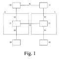
- a first network 1 is shown such as a public fixed network or another public or private network.
- the first network 1 comprises a first network unit 11 coupled to a first subscriber station 10 via a coupling 41 and coupled to a first module 12 via a coupling 51.
- a second network 2 is shown such as a public mobile network or another public or private network.
- the second network 2 comprises a second network unit 21 coupled to a second subscriber station 20 via a coupling 42 and coupled to a second module 22 via a coupling 52.
- the first and second network units 11 and 21 are coupled to each other via a coupling 43.
- the first and second modules 12 and 22 are coupled to each other via a coupling 61.
- the network units 11 and 21 for example each comprise a switch, a router, a forwarder, a multiplexer, a server etc.
- a first subscriber who wants to communicate with a second subscriber via a "normal" connection takes the first subscriber station 10 and dials a "real" number of the second subscriber station 20.
- a "normal" connection is set up from the first subscriber station 10 via the coupling 41 and the network unit 11 and the coupling 43 and the network unit 21 and the coupling 42 to the second subscriber station 20.
- the first subscriber is charged for this "normal" connection.
- a first subscriber who wants to communicate with a second subscriber via a "call back" connection takes the first subscriber station 10 and dials for example a "virtual" number of the second subscriber station 20. This "virtual" number is different from the "real" number of the second subscriber station 20.
- the first network unit 11 collects first information.
- the first information comprises at least a part of a first identification of the first subscriber station 10 via which the connection has been initiated, such as for example a telephone number of the first subscriber station 10. This way, at least a first part of the connection is defined. This first part for example corresponds with the coupling 41.
- the first information further comprises at least a part of a second identification of the second subscriber station 20 that is to be called, such as for example the "virtual" number of the second subscriber station 20.
- a charging control of at least an interconnection between the first and second networks 1 and 2 is to be performed outside the first network 1, such as for example inside the second network 2.
- the first part of the connection is for example set up and is for example kept open, without having excluded other options.
- the first network unit 11 sends the first information to the first module 12 via the coupling 51.
- the first module 12 sends second information to the second module 22, for example via the coupling 61, such as a data connection, or via the couplings 51, 43 and 52.
- the second information may be identical to the first information or may be partly or entirely different from the first information.
- the first module 12 may take care of a conversion.
- the second information comprises for example at least a part of the first identification of the first subscriber station 10 via which the connection has been initiated, such as for example the telephone number of the first subscriber station 10, or comprises for example a link to this first identification of the first subscriber station 10 or comprises for example a link to the first information.
- the second information further comprises at least a part of the second identification of the second subscriber station 20 that is to be called, such as for example the "real" number of the second subscriber station 20, whereby for example the first module 12 has converted the "virtual" number of the second subscriber station 20 into the "real" number of this second subscriber station 20 (which second identification may further be used as one or more of the links mentioned before).
- the charging control of at least the interconnection is to be performed outside the first network 1, such as for example inside the second network 2.
- the (parts of the) first (if available) and second identifications of the first and second subscriber stations 10 and 20 further define a second part of the connection, such as for example the coupling 42.
- the second module 22 receives the second information and in response sends a set up instruction to the second network unit 21.
- the second network unit 21 in response sets up the second part of the connection within the second network.
- This second part of the connection for example corresponds with the coupling 42.
- the connection comprises the first part, the interconnection and the second part.
- the interconnection for example corresponds with the coupling 43 and forms a coupling between the second part and the first part such that the first and second subscriber stations 10 and 20 can communicate.
- the setting up of the first part, the interconnection and the second part may be performed in this particular order or according to another sequence. As a result, a "call back" call has been set up without a "normal" call needing to precede this "call back" call.
- a first subscriber who wants to communicate with a second subscriber via a connection takes the first subscriber station 10 and dials for example a "real" number of the second subscriber station 20.
- the first network unit 11 collects first information.
- the first information comprises at least a part of a first identification of the first subscriber station 10 via which the connection has been initiated, such as for example a telephone number of the first subscriber station 10. This way, at least a first part of the connection is defined. This first part for example corresponds with the coupling 41.
- the first information further comprises at least a part of a second identification of the second subscriber station 20 that is to be called, such as for example the "real" number of the second subscriber station 20.
- a conversion is to be made for converting the "real" number or another "dialed” number into a "virtual" number.
- a possible way to realize this is by introducing a database or an application in or near the first network 1 that for example in dependence of a user setting (such as a user preference etc.) or another parameter (such as a time, a date etc.) makes the conversion, without having excluded other options.
- This database may partly or entirely form part of the first network unit 11, or not.
- Via the "virtual" number it is defined that a charging control of at least an interconnection between the first and second networks 1 and 2 is to be performed outside the first network 1, such as for example inside the second network 2.
- the first network unit 11 sends the converted first information to the first module 12 via the coupling 51 or, in case of the database or the application partly or entirely forming part of the first module 12, the first network unit 11 sends the first information to the first module 12 for being converted.
- the first module 12 sends second information to the second module 22, for example via the coupling 61, such as a data connection, or via the couplings 51, 43 and 52.
- the second information may be identical to the first information or may be partly or entirely different from the first information.
- the first module 12 may take care of a conversion.
- the second information comprises at least a part of the first identification of the first subscriber station 10 (if available) via which the connection has been initiated, such as for example the telephone number of the first subscriber station 10, or comprises for example a link to this first identification of the first subscriber station 10 or comprises for example a link to the first information.
- the second information further comprises at least a part of the second identification of the second subscriber station 20 that is to be called, such as for example the "real" number of the second subscriber station 20, whereby for example the database or the application has converted the "dialed" number into the "virtual” number and whereby the first module 12 has converted the "virtual" number of the second subscriber station 20 into the "real" number of this second subscriber station 20.
- the second information may comprise for example the "virtual" number of the second subscriber station 20, whereby for example the second module 22 will take care of a conversion of this "virtual" number into the "real" number of the second subscriber station 20 (which second identification may further be used as one or more of the links mentioned before).
- the charging control of at least the interconnection is to be performed outside the first network 1, such as for example inside the second network 2.
- the (parts of the) first (if available) and second identifications of the first and second subscriber stations 10 and 20 further define a second part of the connection, such as for example the coupling 42.
- the second module 22 receives the second information etc. as described above for the first option.
- the invention provides features for an automatic and user hidden call back procedure based on a network centric solution. It is a converged network solution because the features may need to be supported by both networks at a functional and an administration layer. Due to the network centric character of the solution additional features do not need to be implemented in the telephone equipment and a specific manual handling necessary from the users point of view is not required.
- the invention may be beneficial for
- the network or service operator is in a position to offer specific and high sophisticated telecommunication services.
- the first and second modules 12 and 22 can be applications on top of an SCP (Service Control Point) following an IN (Intelligent Network) recommendation, on top of the CSE (CAMEL Service Environment) following a CAMEL (Customized Application for Mobile Enhanced Logic) recommendation, on top of a SN (Service Node) connected via e.g. ISUP (ISDN User Part) protocol, on top of an OSA Application Server or can be applications integrated in the network units 11 and 21.
- SCP Service Control Point
- IN Intelligent Network
- CSE CAMEL Service Environment
- CAMEL Customerized Application for Mobile Enhanced Logic
- SN Service Node
- ISUP ISDN User Part
- OSA Application Server can be applications integrated in the network units 11 and 21.
- SIP Session Initiated Protocol
- VoIP equipment and IP equipment and further equipment are not to be excluded either.
- the second subscriber of the second network 2 uses the second subscriber station 20 and has a dedicated mobile number (a "real" number) e.g. +49 177 448 788 which addresses the second subscriber station 20 and a "virtual fix net number" (a "virtual" number) e.g. +49 211 232323 which for example belongs to the number range of the network operator of the first network 1. This virtual fix net number has no physical termination in the first network 1. Calls to this number will be routed to the second network 2 and terminate to a mobile number.
- a dedicated mobile number e.g. +49 177 448 788 which addresses the second subscriber station 20
- a "virtual fix net number" e.g. +49 211 232323 which for example belongs to the number range of the network operator of the first network 1.
- This virtual fix net number has no physical termination in the first network 1. Calls to this number will be routed to the second network 2 and terminate to a mobile number.
- virtual fix net number the second subscriber communicates a “virtual fix net number” but receives the calls to this number at the second subscriber station 20 and the invention takes care that the operator of the second network 2 controls the calls and the charging for the call leg between the second network 2 and the first network 1.
- an exemplary high level architecture for an applicable scenario might be as follows, without excluding alternatives:
- the first module 12 may communicate with the second module 22 directly via a data connection (coupling 61 e.g. Internet, GPRS ....) using an appropriate IT protocol.
- the parameter needed for the "call back" call e.g. the correlation ID and the numbers of the first and second subscribers have to be transferred from the first module 12 to the second module 22.
- the correlation ID is an exemplary embodiment only and may be replaced by other numbers, indications, definitions etc.
- a first network 1 is shown such as a public fixed network or another public or private network.
- the first network 1 comprises a first network unit 11 coupled to a first subscriber station 10 via a coupling 41.
- a second network 2 is shown such as a public mobile network or another public or private network.
- the second network 2 comprises a second network unit 21 coupled to a second subscriber station 20 via a coupling 42 and coupled to a second module 22 via a coupling 52.
- the first and second network units 11 and 21 are coupled to each other via a coupling 43.
- a third network 3 is shown such as a private fixed network or another public or private network.
- the third network 3 comprises a third network unit 31 coupled to a third subscriber station 30 via a coupling 44 and coupled to a third module 32 via a coupling 53.
- the first and third network units 11 and 31 are coupled to each other via a coupling 45.
- the second and third network units 21 and 31 are coupled to each other via a coupling 46.
- the second and third modules 22 and 32 are coupled to each other via a coupling 62.
- the network units 11, 21 and 31 for example each comprise a switch, a router, a forwarder, a multiplexer, a server etc.
- the second module 22 can be an application on top of an SCP (Service Control Point) following the IN (Intelligent Network) recommendation, on top of the CSE (CAMEL Service Environment) following the CAMEL (Customized Application for Mobile Enhanced Logic) recommendation, on top of a SN (Service Node) connected via e.g. ISUP (ISDN User Part), on top of an OSA Application Server protocol or can be an application integrated in the second network unit 21 of the second network 2.
- the third module 32 can be an application on top of a separate system connected to the third network unit 31 or the third module 32 can be fully or partly integrated in the third network unit 31. Further, SIP (Session Initiated Protocol) equipment, VoIP equipment and IP equipment and further equipment are not to be excluded either.
- the second subscriber uses two subscriber stations 20 and 30 in the second network 2 and in the third network 3.
- the third subscriber station 30 can be a fix net telephone set or a IP telephone set served by the third network unit 31.
- the idea of this combination is that the second subscriber is reachable under one number (typically the number of the third subscriber station 30). In case of an incoming call this combination ensures that the second and third subscriber stations 20 and 30 are ringing in parallel and the second subscriber has the choice to receive the call at one of them.
- the invention takes care that the operator of the second network 2 controls the calls and the charging for the call legs between the second network 2 and the first network 1, in case the second subscriber is receiving the call via the second subscriber station 20.
- an exemplary high level architecture for an applicable scenario might be as follows, without excluding alternatives:
- the third module 32 may communicate with the second module 22 directly via a data connection (coupling 62 e.g. Internet, GPRS ....) using an appropriate IT protocol.
- the parameter needed for the "call back" call e.g. the correlation ID, the number of the called party (the second subscriber) and the number of the caller (the first subscriber) have to be transferred from the third module 32 to the second module 22.
- the correlation ID is an exemplary embodiment only and may be replaced by other numbers, indications, definitions etc.
- the interconnection is realized via a more direct connection between the second and third network units 21 and 31 (coupling 46), whereby the first network 1 is only used to couple the first subscriber station 10 to the third network unit 31 etc.
- the third and second networks 3 and 2 may be used for realizing "call forwarding" from the third network 3 to the second network 2, without any "parallel ringing" taking place and without the third subscriber station 30 being involved.
- the second subscriber station 20 belongs to the same company that pays for calls via the unit 31 (typically a PBX) and a price "y per minute" for calling from the second network 2 to the first network is lower than the price "x per minute” for calling from the first network 1 to the second network 2, the company will safe money for the communications.
- the unit 31 typically a PBX
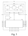
- an arrangement 71 according to the invention comprising a module 82 according to the invention.
- the arrangement 71 for example corresponds with a network or with a part thereof such as a network unit 11, 21 or 31 such as switches, routers, forwarders, multiplexers, servers etc.
- the module 82 for example corresponds with one of the first, second and third modules 12, 22 and 32.
- the arrangement 71 comprises for example a switch 72 coupled to a controller 73 and to an interface 86 of the module 82.
- the module 82 further comprises for example a receiver 83, a controller 84 and a sender 85 all coupled to the interface 86.
- the controller 84 is further coupled to the receiver 83 and the sender 85.
- the module 82 may be located outside the arrangement 71.
- the controllers 73 and 84 may comprise storages and may comprise detectors for detecting incoming signals and generators for generating outgoing signals and converters for converting signals etc. all not shown.
- the term "signal" may be "information", "instruction” etc.
- a charging control of (the interconnection between the different networks 1,2 or 2,3 of) the call may be performed inside the second network 2 and/or a call control of (the interconnection between the different networks 1,2 or 2,3 of) the call may be performed inside the second network 2.
- the first subscriber is also billed for the "call back" call, such as billing this first subscriber for a fixed amount per call or such as billing the first subscriber for a smaller part of the bill whereby the second subscriber is billed for a larger part of this bill.
- the first and second subscribers are in the Fig. 1 and 2 coupled directly to the first and second and third networks 1, 2 and 3. It is however not to be excluded that a subscriber is coupled indirectly to a network, for example via a further network such as a Voice over Internet Protocol or VoIP network.
- the blocks 10, 20 and/or 30 may represent gateways such as VoIP gateways etc.
- Each network may comprise two or more sub-networks, each coupling may be a wired or wireless coupling and may comprise two or more sub-couplings and/or one or more network units, without departing from the scope of this invention.
- the second and third subscriber stations 20 and 30 might form part of one physical subscriber station comprising different transceivers, and each subscriber station 10, 20, 30 may be of any kind.
- Each piece of the invention may be divided into two or more smaller pieces, and two or more pieces of the invention may be combined into a larger piece, without departing from the scope of this invention.
- first networks 1 e.g. public fixed networks
- first information is received defining at least first parts of the connections within the first networks 1.
- second information is sent to second networks 2 e.g. public mobile networks defining the charging control of at least the interconnections to be performed outside the first networks 1 and defining at least second parts of the connections.
- third step the second parts of the connections are set up within the second networks 2.
- the connections comprise the first parts, the interconnections and the second parts. This way, "call back" calls can be set up without "normal” calls needing to precede these "call back” calls.
- a computer program product may be stored / distributed on a suitable medium, such as an optical storage medium or a solid-state medium supplied together with or as part of other hardware, but may also be distributed in other forms, such as via the Internet or other wired or wireless telecommunication systems. Any reference signs in the claims should not be considered to limit the scope.
Landscapes
- Engineering & Computer Science (AREA)
- Computer Networks & Wireless Communication (AREA)
- Signal Processing (AREA)
- Telephonic Communication Services (AREA)
- Mobile Radio Communication Systems (AREA)
- Meter Arrangements (AREA)
- Data Exchanges In Wide-Area Networks (AREA)
Abstract
Description
- The invention relates to a method for setting up a connection via an interconnection between different networks, and also relates to a first module for a first network, to a first sub-method for a first network, to a second module for a second network, to a second sub-method for a second network, to a third module for a third network, to a third sub-method for a third network, and to an arrangement comprising a module.
- Examples of such different networks are first networks such as public fixed networks and other kinds of public or private networks, second networks such as public mobile networks and other kinds of public or private networks, and third networks such as private fixed networks and other kinds of public or private networks. Examples of such arrangements are networks and parts thereof such as switching centres, servers, switches, routers, forwarders, multiplexers, and other network units.
- A prior art method is known in general. To set up a "normal" call from a first subscriber in a first network to a second subscriber in a second network, the first subscriber dials a telephone number of the second subscriber, and in response the first network sets up a part of the "normal" call from the first subscriber to a border between the first and second networks and the second network sets up another part of the "normal" call from the border between the first and second networks to the second subscriber. As soon as the second subscriber has accepted the "normal" call, the first and second subscribers can start a communication with each other. The first subscriber is charged for this call.
- To charge the second subscriber for the communication, a "call back" call is to be set up. Thereto, the second subscriber does not accept the "normal" call from the first subscriber, but the "normal" call is only used to inform the second subscriber that the first subscriber would like to communicate. To set up the "call back" call, the second subscriber waits until the first subscriber has ceased the "normal" call and then dials a telephone number of the first subscriber, and in response the second network sets up a part of the "call back" call from the second subscriber to a border between the first and second networks and the first network sets up another part of the "call back" call from the border between the first and second networks to the first subscriber. As soon as the first subscriber has accepted the "call back" call, the first and second subscribers can start a communication with each other. The second subscriber is charged for this call.
- The prior art method is disadvantageous, inter alia, in that the first subscriber must start the "normal" call and then cease the "normal" call before the first subscriber can accept the "call back" call from the second subscriber.
- It is an object of the invention, inter alia, to provide a method for setting up a connection via an interconnection between different networks, from a first subscriber in a first network to a second subscriber in a second network, whereby (mainly) the second subscriber is charged for the connection, without separate "normal" and "call back" connections needing to be set up.
- Further objects of the invention are, inter alia, to provide a first module for a first network, a first sub-method for a first network, a second module for a second network, a second sub-method for a second network, a third module for a third network, a third sub-method for a third network, and an arrangement comprising a module.
- According to a first aspect of the invention, a method as defined in
claim 1 is provided. - In a first network such as for example a public fixed network (first step), first information is received, which first information defines at least a first part of the connection within the first network. The first information arrives for example at a first network unit and originates for example from a first subscriber station possibly via a further first network unit and comprises for example at least a part of a first identification of the first subscriber station via which the connection has been initiated and at least a part of a second identification of the second subscriber station that is to be called. According to a first option, the second identification of the second subscriber station is such that this second identification further defines that the charging control of at least the interconnection is not to be performed by the first network but that it is to be performed by another network. A possible way to realize this is by giving the second subscriber station two telephone numbers, one for being called via "normal" connections and one other for being called via "call back" connections, without having excluded other options. According to a second option, the second identification of the second subscriber station is a "normal" identification, whereby in or near the first network a conversion is to be made for converting the "normal" identification into a "call back" identification. A possible way to realize this is by introducing a database in or near the first network that for example in dependence of a user setting (such as a user preference etc.) or another parameter (such as a time, a date etc.) makes the conversion, without having excluded other options. The first part of the connection is for example a first leg between the first subscriber station and the first network unit or between the further first network unit and the first network unit. Before the first information is received by the first network unit, while the first information is being received by the first network unit, or after the first information has been received by the first network unit, the first part of the connection is for example set up and is for example kept open, without having excluded other options.
- In response to the reception of the first information (second step), second information is sent to a second network such as for example a public mobile network, which second information defines the charging control of at least the interconnection to be performed outside the first network and defines at least a second part of the connection. The second information originates for example from the first network unit when comprising a first module or originates for example from the first module when being coupled to the first network unit and may be identical to the first information or may be partly or entirely different from the first information. The second information comprises for example at least a part of the first identification of the first subscriber station or comprises for example a link to this first identification of the first subscriber station or comprises for example a link to the first information and comprises at least a part of the second identification of the second subscriber station (which second identification may further be used as one or more of the links mentioned before). The second identification of the second subscriber station may be or may not be such that this second identification further defines that the charging control of at least the interconnection is not to be performed by the first network but that it is to be performed by another network.
- In the second network (third step), in response to a reception of the second information, the second part of the connection is set up within the second network. The second information arrives for example at a second network unit when comprising a second module or arrives for example at the second module when being coupled to the second network unit. The second part of the connection is for example a second leg between the second network unit and the second subscriber station or between the second network unit and a further second network unit via which the second subscriber station can communicate. The connection comprises the first part, the interconnection and the second part. The interconnection is for example an interconnecting leg between the second network unit and the first network unit and forms a coupling between the second part and the first part such that the first and second subscriber stations can communicate. The setting up of the first part, the interconnection and the second part may be performed in this particular order or according to another sequence.
- This way, a "call back" call can be set up without a "normal" call needing to precede this "call back" call.
- An embodiment of the method is defined in
claim 2. Preferably, the charging control of at least the interconnection is performed by/inside the second network and/or a connection control of at least the interconnection is performed by/inside the second network. - An embodiment of the method is defined in
claim 3. Possibly, a third network may be involved, such as a private fixed network. - In response to the reception of the first information (first sub-step of the second step), third information is sent to a third network. The third information arrives for example at a third network unit and originates for example from the first network unit and comprises for example at least a part of the first identification of the first subscriber station via which the connection has been initiated or comprises for example a pointer to this first identification of the first subscriber station or comprises for example a pointer to the first information and comprises for example either at least a part of the second identification of the second subscriber station that is to be called or at least a part of a third identification of a third subscriber station that is to be called. The second identification of the second subscriber station may be or may not be such that this second identification further defines that the charging control of at least the interconnection is not to be performed by the first network but that it is to be performed by another network.
- In response to a reception of the third information (second sub-step of the second step), the second information is sent to the second network. The second information originates for example from the third network unit when comprising a third module or originates for example from the third module when being coupled to the third network unit and may be identical to the third information or may be partly or entirely different from the third information.
- According to a first possibility (call forwarding), the third network has forwarded the call to the second network. According to a second possibility (parallel ringing), the second and third network will perform "parallel ringing", as follows, and without having excluded further possibilities.
- In the third network, in response to a reception of the third information, a third part of the connection may be set up within the third network. The third part of the connection is for example a third leg between the third network unit and the third subscriber station and may be for example set up to realize "parallel ringing" at the second and third subscriber stations to for example allow the second subscriber to choose between answering the call via the second or the third subscriber station. The connection may further comprise a further interconnection between the first and third networks and the third part. The further interconnection is for example a further interconnecting leg between the third network unit and the first network unit. Alternatively, in this case, the interconnection may be present between the second and third network units, such as an interconnecting leg between these second and third network units. In that case, the first network is only used for coupling the first subscriber station to the third network, and the third network contacts the second network and the interconnection is present between the second and third networks whereby the second network gets the charging control of at least this interconnection between the second and the third network etc.
- This way, a "call back" call can be set up without a "normal" call needing to precede this "call back" call, and the second subscriber has the option of using the second subscriber station for realizing a communication via a "call back" call or the third subscriber station for realizing a communication via a "normal" call.
- According to a second aspect of the invention, a first module as defined in claim 4 for a first network is provided.
- According to a third aspect of the invention, a first sub-method as defined in claim 5 for a first network is provided.
- According to a fourth aspect of the invention, a second module as defined in claim 6 for a second network is provided.
- According to a fifth aspect of the invention, a second sub-method as defined in claim 7 for a second network is provided.
- According to a sixth aspect of the invention, a third module as defined in claim 8 for a third network is provided.
- According to a seventh aspect of the invention, a third sub-method as defined in claim 9 for a third network is provided.
- According to an eighth aspect of the invention, an arrangement as defined in
claim 10 comprising a module is provided. - Embodiments of the modules according to the invention and of the sub-methods according to the invention and of the arrangement according to the invention correspond with the embodiments of the method according to the invention.
- An insight may be that a prior art call back procedure based on separate "normal" and "call back" calls is relatively user unfriendly. A basic idea may be that a call back procedure should be based on one integrated connection comprising a "normal" part and a "call back" part.
- A problem to provide a method for setting up a connection via an interconnection between different networks, from a first subscriber in a first network to a second subscriber in a second network, whereby for example the network operator of the second network has the charging control of the interconnection between the networks and (mainly) the second subscriber can be charged for the connection, without separate "normal" and "call back" calls needing to be set up, is solved. A further advantage may be that an introduction of a new service has become possible.
- These and other aspects of the invention are apparent from and will be elucidated with reference to the embodiments described hereinafter.
- In the drawings:
-
Fig. 1 shows a first schematic diagram of a first situation according to the invention, -
Fig. 2 shows a second schematic diagram of a second situation according to the invention, and -
Fig. 3 shows a third schematic diagram of an arrangement according to the invention comprising a module according to the invention. - In the
Fig. 1 , afirst network 1 is shown such as a public fixed network or another public or private network. Thefirst network 1 comprises afirst network unit 11 coupled to afirst subscriber station 10 via acoupling 41 and coupled to afirst module 12 via acoupling 51. Further, asecond network 2 is shown such as a public mobile network or another public or private network. Thesecond network 2 comprises asecond network unit 21 coupled to asecond subscriber station 20 via acoupling 42 and coupled to asecond module 22 via acoupling 52. The first andsecond network units coupling 43. The first andsecond modules coupling 61. Thenetwork units - A first subscriber who wants to communicate with a second subscriber via a "normal" connection (in for example a prior art non Intelligent Network environment) takes the
first subscriber station 10 and dials a "real" number of thesecond subscriber station 20. In response, a "normal" connection is set up from thefirst subscriber station 10 via thecoupling 41 and thenetwork unit 11 and thecoupling 43 and thenetwork unit 21 and thecoupling 42 to thesecond subscriber station 20. The first subscriber is charged for this "normal" connection. - A first subscriber who wants to communicate with a second subscriber via a "call back" connection (according to a first option of the invention) takes the
first subscriber station 10 and dials for example a "virtual" number of thesecond subscriber station 20. This "virtual" number is different from the "real" number of thesecond subscriber station 20. In response, thefirst network unit 11 collects first information. The first information comprises at least a part of a first identification of thefirst subscriber station 10 via which the connection has been initiated, such as for example a telephone number of thefirst subscriber station 10. This way, at least a first part of the connection is defined. This first part for example corresponds with thecoupling 41. The first information further comprises at least a part of a second identification of thesecond subscriber station 20 that is to be called, such as for example the "virtual" number of thesecond subscriber station 20. This way, it is defined that a charging control of at least an interconnection between the first andsecond networks first network 1, such as for example inside thesecond network 2. Before the first information is received by thefirst network unit 11, while the first information is being received by thefirst network unit 11, or after the first information has been received by thefirst network unit 11, the first part of the connection is for example set up and is for example kept open, without having excluded other options. - The
first network unit 11 sends the first information to thefirst module 12 via thecoupling 51. In response, thefirst module 12 sends second information to thesecond module 22, for example via thecoupling 61, such as a data connection, or via thecouplings first module 12 may take care of a conversion. The second information comprises for example at least a part of the first identification of thefirst subscriber station 10 via which the connection has been initiated, such as for example the telephone number of thefirst subscriber station 10, or comprises for example a link to this first identification of thefirst subscriber station 10 or comprises for example a link to the first information. The second information further comprises at least a part of the second identification of thesecond subscriber station 20 that is to be called, such as for example the "real" number of thesecond subscriber station 20, whereby for example thefirst module 12 has converted the "virtual" number of thesecond subscriber station 20 into the "real" number of this second subscriber station 20 (which second identification may further be used as one or more of the links mentioned before). This way, it is defined that the charging control of at least the interconnection is to be performed outside thefirst network 1, such as for example inside thesecond network 2. The (parts of the) first (if available) and second identifications of the first andsecond subscriber stations coupling 42. - The
second module 22 receives the second information and in response sends a set up instruction to thesecond network unit 21. Thesecond network unit 21 in response sets up the second part of the connection within the second network. This second part of the connection for example corresponds with thecoupling 42. The connection comprises the first part, the interconnection and the second part. The interconnection for example corresponds with thecoupling 43 and forms a coupling between the second part and the first part such that the first andsecond subscriber stations - A first subscriber who wants to communicate with a second subscriber via a connection (according to a second option of the invention) takes the
first subscriber station 10 and dials for example a "real" number of thesecond subscriber station 20. In response, thefirst network unit 11 collects first information. The first information comprises at least a part of a first identification of thefirst subscriber station 10 via which the connection has been initiated, such as for example a telephone number of thefirst subscriber station 10. This way, at least a first part of the connection is defined. This first part for example corresponds with thecoupling 41. The first information further comprises at least a part of a second identification of thesecond subscriber station 20 that is to be called, such as for example the "real" number of thesecond subscriber station 20. Before the first information is received by thefirst network unit 11, while the first information is being received by thefirst network unit 11, or after the first information has been received by thefirst network unit 11, the first part of the connection is for example set up and is for example kept open, without having excluded other options. - But this time, in or near the
first network 1, a conversion is to be made for converting the "real" number or another "dialed" number into a "virtual" number. A possible way to realize this is by introducing a database or an application in or near thefirst network 1 that for example in dependence of a user setting (such as a user preference etc.) or another parameter (such as a time, a date etc.) makes the conversion, without having excluded other options. This database may partly or entirely form part of thefirst network unit 11, or not. Via the "virtual" number, it is defined that a charging control of at least an interconnection between the first andsecond networks first network 1, such as for example inside thesecond network 2. - The
first network unit 11 sends the converted first information to thefirst module 12 via thecoupling 51 or, in case of the database or the application partly or entirely forming part of thefirst module 12, thefirst network unit 11 sends the first information to thefirst module 12 for being converted. In response, thefirst module 12 sends second information to thesecond module 22, for example via thecoupling 61, such as a data connection, or via thecouplings first module 12 may take care of a conversion. The second information comprises at least a part of the first identification of the first subscriber station 10 (if available) via which the connection has been initiated, such as for example the telephone number of thefirst subscriber station 10, or comprises for example a link to this first identification of thefirst subscriber station 10 or comprises for example a link to the first information. The second information further comprises at least a part of the second identification of thesecond subscriber station 20 that is to be called, such as for example the "real" number of thesecond subscriber station 20, whereby for example the database or the application has converted the "dialed" number into the "virtual" number and whereby thefirst module 12 has converted the "virtual" number of thesecond subscriber station 20 into the "real" number of thissecond subscriber station 20. Alternatively, the second information may comprise for example the "virtual" number of thesecond subscriber station 20, whereby for example thesecond module 22 will take care of a conversion of this "virtual" number into the "real" number of the second subscriber station 20 (which second identification may further be used as one or more of the links mentioned before). This way, it is defined that the charging control of at least the interconnection is to be performed outside thefirst network 1, such as for example inside thesecond network 2. The (parts of the) first (if available) and second identifications of the first andsecond subscriber stations coupling 42. - The
second module 22 receives the second information etc. as described above for the first option. - Any operation performed in one of the
modules - So, the invention provides features for an automatic and user hidden call back procedure based on a network centric solution. It is a converged network solution because the features may need to be supported by both networks at a functional and an administration layer. Due to the network centric character of the solution additional features do not need to be implemented in the telephone equipment and a specific manual handling necessary from the users point of view is not required.
- The invention may be beneficial for
- groups of people (staff of company, families) with a common budget or account whereby members of the group use telephone sets accessed to different types of networks,
- individual users of the second network, who want to avoid high communication costs for communication partners calling from external networks, and
- the network or service operator of the second network who wants to have the full call and charging control of terminating calls initiated in external networks.
- With the features the network or service operator is in a position to offer specific and high sophisticated telecommunication services.
- In view of the
Fig. 1 , the first andsecond modules network units - The second subscriber of the
second network 2 uses thesecond subscriber station 20 and has a dedicated mobile number (a "real" number) e.g. +49 177 448 788 which addresses thesecond subscriber station 20 and a "virtual fix net number" (a "virtual" number) e.g. +49 211 232323 which for example belongs to the number range of the network operator of thefirst network 1. This virtual fix net number has no physical termination in thefirst network 1. Calls to this number will be routed to thesecond network 2 and terminate to a mobile number. The idea of the service "virtual fix net number" is that the second subscriber communicates a "virtual fix net number" but receives the calls to this number at thesecond subscriber station 20 and the invention takes care that the operator of thesecond network 2 controls the calls and the charging for the call leg between thesecond network 2 and thefirst network 1. - In view of the
Fig. 1 , an exemplary high level architecture for an applicable scenario might be as follows, without excluding alternatives: - the first subscriber wants to communicate with the second subscriber via phone and dials the "virtual fix net number" of the second subscriber at the
first subscriber station 10 such as a telephone set, - the dialed digits are transferred to the
first network unit 11 such as a fixed net switching centre, - the
first network unit 11 routes the call to thefirst module 12 and the first module 12 (in thisexample module 12 acts as a Service Node) receives the call attempt from the first subscriber (via a first channel of the coupling 51), - in the
first module 12 the "virtual fix net number" and the mobile number of the second subscriber are administrated in a way that the application of thisfirst module 12 can identify the mobile number of the second subscriber who has subscripted the "virtual fix net number" service, and thefirst module 12 generates a correlation ID, which identifies this dedicated call, - the
first module 12 routes the call ("Initial Address Message") to the secondmobile network 2 via the first network unit 11 (via a second channel of thecoupling 51 and via a first channel of thecoupling 43 in theFig. 1 ), - the correlation ID and the mobile number of the second subscriber and the number of the first subscriber are combined by the
first module 12 and a combination is transported via signaling protocols such as ISUP using Initial Address Message to thesecond network unit 21 such as a mobile switching centre in thesecond network 2, - the
second network unit 21 triggers and invokes thesecond module 22 using the INAP or the CAMEL protocol (via a first channel of thecoupling 52 in theFig. 1 ), - the
second network unit 21 takes care of the transfer of the correlation ID, the mobile number of the second subscriber and the number of the first subscriber to thesecond module 22, - the
second module 22 recognizes the call attempt based on the correlation ID and fetches the call parameters but the call attempt is not accepted, - the
second module 22 instructs thesecond network unit 21 by using the INAP or CAMEL protocol to release the call (via the first channel of thecoupling 43 and the second channel of the coupling 51) to thefirst module 12, but the first channel of thecoupling 51 and thecoupling 41 are still active, - the
second module 22 instructs thesecond network unit 21 by using the INAP or CAMEL protocol to establish a call leg back to the first module 12 (via a second channel of thecoupling 43 and a third channel of thecoupling 51 in theFig. 1 ), - the correlation ID is transported to the
first module 12 via thefirst network unit 11 using e.g. the ISUP protocol, - the
first module 12 can identify the specific call scenario by analyzing the correlation ID, - the
first module 12 accepts the incoming call leg by sending a response message back to thesecond network unit 21 via thefirst network unit 11 and interconnects the call leg of the new incoming call from thesecond network unit 21 with the call leg of thefirst subscriber station 10, and - the
second network unit 21 informs thesecond module 22 by using the INAP or CAMEL protocol, that the call was answered by thefirst module 12, - the
second module 22 instructs thesecond network unit 21 by using the INAP or CAMEL protocol to establish another call leg to thesecond subscriber station 20 of the second subscriber (coupling 42) and further instructs thesecond network unit 21 to interconnect the new call leg to thesecond subscriber 20 with the call leg to thefirst module 12 and the first and second subscriber can start communication, when the call is answered by thesecond subscriber station 20 of the second subscriber, and - the
second network unit 21 of thesecond network 2 generates a Call Data Record for the interconnection (coupling 43) between thenetwork - Instead of routing the call by using the signaling capability of the networks typically based on the ISUP protocol, the
first module 12 may communicate with thesecond module 22 directly via a data connection (coupling 61 e.g. Internet, GPRS ....) using an appropriate IT protocol. The parameter needed for the "call back" call e.g. the correlation ID and the numbers of the first and second subscribers have to be transferred from thefirst module 12 to thesecond module 22. Further, the correlation ID is an exemplary embodiment only and may be replaced by other numbers, indications, definitions etc. - In the
Fig. 2 , afirst network 1 is shown such as a public fixed network or another public or private network. Thefirst network 1 comprises afirst network unit 11 coupled to afirst subscriber station 10 via acoupling 41. Further, asecond network 2 is shown such as a public mobile network or another public or private network. Thesecond network 2 comprises asecond network unit 21 coupled to asecond subscriber station 20 via acoupling 42 and coupled to asecond module 22 via acoupling 52. The first andsecond network units coupling 43. Further, athird network 3 is shown such as a private fixed network or another public or private network. Thethird network 3 comprises athird network unit 31 coupled to athird subscriber station 30 via acoupling 44 and coupled to athird module 32 via acoupling 53. The first andthird network units coupling 45. The second andthird network units coupling 46. The second andthird modules coupling 62. Thenetwork units - In view of the
Fig. 2 , thesecond module 22 can be an application on top of an SCP (Service Control Point) following the IN (Intelligent Network) recommendation, on top of the CSE (CAMEL Service Environment) following the CAMEL (Customized Application for Mobile Enhanced Logic) recommendation, on top of a SN (Service Node) connected via e.g. ISUP (ISDN User Part), on top of an OSA Application Server protocol or can be an application integrated in thesecond network unit 21 of thesecond network 2. Thethird module 32 can be an application on top of a separate system connected to thethird network unit 31 or thethird module 32 can be fully or partly integrated in thethird network unit 31. Further, SIP (Session Initiated Protocol) equipment, VoIP equipment and IP equipment and further equipment are not to be excluded either. - The second subscriber uses two
subscriber stations second network 2 and in thethird network 3. Thethird subscriber station 30 can be a fix net telephone set or a IP telephone set served by thethird network unit 31. The idea of this combination is that the second subscriber is reachable under one number (typically the number of the third subscriber station 30). In case of an incoming call this combination ensures that the second andthird subscriber stations second network 2 controls the calls and the charging for the call legs between thesecond network 2 and thefirst network 1, in case the second subscriber is receiving the call via thesecond subscriber station 20. - In view of the
Fig. 2 , an exemplary high level architecture for an applicable scenario might be as follows, without excluding alternatives: - the first subscriber wants to communicate with the second subscriber and the first subscriber dials the number of the
third subscriber station 30 using e.g. thefirst subscriber station 10 served by thefirst network 1, - the dialed digits are transferred to the
first network unit 11 such as a fixed net switching centre of thefirst network 1, - the call is routed by the
first network unit 11 to thethird network unit 31 in the third network 3 (via a first channel of the coupling 45), - the
third network unit 31 is configured in a way that the call is routed to thethird module 32 and thisthird module 32 receives the call attempt from the first subscriber (via a first channel of the coupling 53), and thethird network unit 31 starts a call attempt to the third subscriber station 30 (via the coupling 44), - the
third module 32 in combination with thethird network unit 31 starts a call attempt (Temporary Call Attempt) to the second network 2 (via second channels of thecouplings - in the signaling of the temporary call attempt to the
second network 2, a correlation ID, which identifies this dedicated call, generated by thethird module 32, and the numbers of the first, if available and second subscribers are included using e.g. the QSIG protocol in a private network and ISUP in a public networks, - the
second network unit 21 triggers and invokes thesecond module 22 using the INAP or the CAMEL protocol (via a first channel of the coupling 52), - the
second network unit 21 takes care for the transfer of the parameters such as the correlation ID and the numbers of the first, if available and second subscribers to thesecond module 22, - the
second module 22 recognizes the temporary call attempt and fetches the call parameters but the call attempt is not accepted, - the
second module 22 instructs the second network unit 21 (via a second channel of the by using the INAP or CAMEL protocol to release the call (the first channel of thecoupling 43 and the second channels of thecouplings 45 and 53) to thethird module 32, but the first channels of thecouplings coupling 41 are still active, - the
second module 22 instructs (via the second channel of the coupling 52) thesecond network unit 21 by using the INAP or CAMEL protocol to establish a call leg back to the third module 32 (via a second channel of thecoupling 43 and via a second channel of thecoupling 45 and via a third channel of the coupling 53), - the correlation ID is transported to the
third module 32 via thefirst network unit 11 using e.g. the ISUP protocol in a public network and via thethird network unit 31 using e.g. QSIG in a private network, - the
third module 32 can identify the specific call scenario by analyzing the correlation ID, - the
third module 32 accepts the incoming call leg by sending a response message back to thesecond network unit 21 via thefirst network unit 11 andthird network unit 31 and interconnects the call leg of the new incoming call from thesecond network unit 21 with the call leg of thefirst subscriber station 10 via thethird network unit 31, and - the
second network unit 21 informs thesecond module 22 by using the INAP or CAMEL protocol, that the call was answered by thethird module 32, - the
second module 22 instructs thesecond network unit 21 by using the INAP or CAMEL protocol to establish another call leg to thesecond subscriber station 20 of the second subscriber (coupling 42) and further instructs thesecond network unit 21 to interconnect the new call leg to thesecond subscriber 20 with the call leg to thethird module 32, and - in this stage the involved modules and systems take care for the parallel ringing at the second and
third subscriber stations - if the
second subscriber station 20 takes the call thethird network unit 31 releases the call leg to thethird subscriber station 30 and the first and second subscribers can start the communication, - the
second network unit 21 of thesecond network 2 generates a Call Data Record for the interconnection (coupling 43) between thenetwork - Instead of routing the call by using the signaling capability of the networks typically based on the ISUP protocol respectively the QSIG protocol, the
third module 32 may communicate with thesecond module 22 directly via a data connection (coupling 62 e.g. Internet, GPRS ....) using an appropriate IT protocol. The parameter needed for the "call back" call e.g. the correlation ID, the number of the called party (the second subscriber) and the number of the caller (the first subscriber) have to be transferred from thethird module 32 to thesecond module 22. Further, the correlation ID is an exemplary embodiment only and may be replaced by other numbers, indications, definitions etc. - Alternatively, the interconnection is realized via a more direct connection between the second and
third network units 21 and 31 (coupling 46), whereby thefirst network 1 is only used to couple thefirst subscriber station 10 to thethird network unit 31 etc. - Further alternatively, instead of realizing "parallel ringing", the third and
second networks third network 3 to thesecond network 2, without any "parallel ringing" taking place and without thethird subscriber station 30 being involved. - For example, if the
second subscriber station 20 belongs to the same company that pays for calls via the unit 31 (typically a PBX) and a price "y per minute" for calling from thesecond network 2 to the first network is lower than the price "x per minute" for calling from thefirst network 1 to thesecond network 2, the company will safe money for the communications. - In the
Fig. 3 , anarrangement 71 according to the invention is shown comprising amodule 82 according to the invention. Thearrangement 71 for example corresponds with a network or with a part thereof such as anetwork unit module 82 for example corresponds with one of the first, second andthird modules - The
arrangement 71 comprises for example aswitch 72 coupled to acontroller 73 and to aninterface 86 of themodule 82. Themodule 82 further comprises for example areceiver 83, acontroller 84 and asender 85 all coupled to theinterface 86. Thecontroller 84 is further coupled to thereceiver 83 and thesender 85. Alternatively, themodule 82 may be located outside thearrangement 71. Thecontrollers - So, preferably, a charging control of (the interconnection between the
different networks second network 2 and/or a call control of (the interconnection between thedifferent networks second network 2. This does however not exclude the possibility that the first subscriber is also billed for the "call back" call, such as billing this first subscriber for a fixed amount per call or such as billing the first subscriber for a smaller part of the bill whereby the second subscriber is billed for a larger part of this bill. - The first and second subscribers are in the
Fig. 1 and2 coupled directly to the first and second andthird networks blocks third subscriber stations subscriber station - Summarizing, to set up connections via interconnections between
different networks first networks 1 e.g. public fixed networks (first step), first information is received defining at least first parts of the connections within thefirst networks 1. In response, (second step) second information is sent tosecond networks 2 e.g. public mobile networks defining the charging control of at least the interconnections to be performed outside thefirst networks 1 and defining at least second parts of the connections. In response, (third step) the second parts of the connections are set up within thesecond networks 2. The connections comprise the first parts, the interconnections and the second parts. This way, "call back" calls can be set up without "normal" calls needing to precede these "call back" calls. - While the invention has been illustrated and described in detail in the drawings and the description, these drawings and this description are considered to be illustrative disclosures or exemplary disclosures, but not restrictive disclosures. The invention is not limited to the described embodiments. Other variations to the disclosed embodiments can be understood and effected by a person skilled in the art. In the claims, the word "comprising" does not exclude other elements or steps, and the indefinite article "a" or "an" does not exclude a plurality. A single processor or other single unit may fulfill the functions of several items recited in the claims. The mere fact that certain features are recited in mutually different dependent claims does not indicate that a combination of these measured cannot be used to advantage. A computer program product may be stored / distributed on a suitable medium, such as an optical storage medium or a solid-state medium supplied together with or as part of other hardware, but may also be distributed in other forms, such as via the Internet or other wired or wireless telecommunication systems. Any reference signs in the claims should not be considered to limit the scope.
Claims (10)
- A method for setting up a connection via an interconnection between different networks (1, 2), the method comprising - a first step of, in a first network (1), receiving first information, which first information defines at least a first part of the connection within the first network (1),- a second step of, in response to the reception of the first information, sending second information to a second network (2), which second information defines the charging control of at least the interconnection to be performed outside the first network (1) and defines at least a second part of the connection, and- a third step of, in the second network (2), in response to a reception of the second information, setting up the second part of the connection within the second network (2), the connection comprising the first part, the interconnection and the second part.
- A method as defined in claim 1, the charging control of at least the interconnection being performed inside the second network (2) and/or a connection control of at least the interconnection being performed inside the second network (2).
- A method as defined in claim 1, the method further comprising- in the second step, a first sub-step of, in response to the reception of the first information, sending third information to a third network (3), and- in the second step, a second sub-step of, in response to a reception of the third information, sending the second information to the second network (2).
- A first module (12) for a first network (1) for setting up a connection via an interconnection between different networks (1, 2), the first module (12) comprising- a first receiver for receiving first information, which first information defines at least a first part of the connection within the first network (1), and- a first sender for, in response to a reception of the first information, sending second information to a second module (22) at a second network (2), which second information defines the charging control of at least the interconnection to be performed outside the first network (1) and defines at least a second part of the connection, the second part of the connection being located within the second network (2), the connection comprising the first part, the interconnection and the second part.
- A first sub-method for a first network (1) for setting up a connection via an interconnection between different networks (1, 2), the first sub-method comprising the steps of- receiving first information, which first information defines at least a first part of the connection within the first network (1), and- in response to a reception of the first information, sending second information to a second module (22) at a second network (2), which second information defines the charging control of at least the interconnection to be performed outside the first network (1) and defines at least a second part of the connection, the second part of the connection being located within the second network (2), the connection comprising the first part, the interconnection and the second part.
- A second module (22) for a second network (2) for setting up a connection via an interconnection between different networks (1, 2)(2, 3), the second module (22) comprising- a second receiver for receiving second information from a first module (12) at a first network (1) or from a third module (32) at a third network (3), which second information defines a charging control of at least the interconnection to be performed outside the first network (1) and defines at least a second part of the connection, and- a second sender for, in response to a reception of the second information, sending a set up instruction for setting up the second part of the connection within the second network (2), the connection comprising a first part, the interconnection and the second part, the first part of the connection being located within the first network (1).
- A second sub-method for a second network (2) for setting up a connection via an interconnection between different networks (1, 2)(2, 3), the second sub-method comprising the steps of- receiving second information from a first module (12) at a first network (1) or from a third module (32) at a third network (3), which second information defines a charging control of at least the interconnection to be performed outside the first network (1) and defines at least a second part of the connection, and- in response to a reception of the second information, sending a set up instruction for setting up the second part of the connection within the second network (2), the connection comprising a first part, the interconnection and the second part, the first part of the connection being located within the first network (1).
- A third module (32) for a third network (3) for setting up a connection via an interconnection between different networks (1, 2)(2, 3), the third module (32) comprising- a third receiver for receiving third information from a first network (1), and- a third sender for, in response to a reception of the third information, sending second information to a second module (22) at a second network (2), which second information defines the charging control of at least the interconnection to be performed outside the first network (1) and defines at least a second part of the connection, the second part of the connection being located within the second network (2), a first part of the connection being located within the first network (1), the connection comprising the first part, the interconnection and the second part.
- A third sub-method for a third network (3) for setting up a connection via an interconnection between different networks (1, 2)(2, 3), the third sub-method comprising the steps of- receiving third information from a first network (1), and- in response to a reception of the third information, sending second information to a second module (22) at a second network (2), which second information defines the charging control of at least the interconnection to be performed outside the first network (1) and defines at least a second part of the connection, the second part of the connection being located within the second network (2), a first part of the connection being located within the first network (1), the connection comprising the first part, the interconnection and the second part.
- An arrangement (71) comprising the module (12, 22, 32, 82) as defined in claim 4, 6 or 8.
Priority Applications (7)
| Application Number | Priority Date | Filing Date | Title |
|---|---|---|---|
| EP07011417A EP2003868A1 (en) | 2007-06-11 | 2007-06-11 | Setting up a connection via an interconnection between different networks |
| CN200880019764.8A CN101682679B (en) | 2007-06-11 | 2008-06-11 | Reverse calls are established via the interconnection between different networks |
| US12/663,449 US8730947B2 (en) | 2007-06-11 | 2008-06-11 | Reverse call set up via an interconnection between different networks |
| EP08759178.0A EP2168367B1 (en) | 2007-06-11 | 2008-06-11 | Split call set-up between different networks |
| PCT/EP2008/004668 WO2008151786A1 (en) | 2007-06-11 | 2008-06-11 | Reverse call set up via an interconnection between different networks |
| AU2008261230A AU2008261230B2 (en) | 2007-06-11 | 2008-06-11 | Reverse call set up via an interconnection between different networks |
| JP2010511533A JP5611037B2 (en) | 2007-06-11 | 2008-06-11 | Setting up connections through interconnections between different networks |
Applications Claiming Priority (1)
| Application Number | Priority Date | Filing Date | Title |
|---|---|---|---|
| EP07011417A EP2003868A1 (en) | 2007-06-11 | 2007-06-11 | Setting up a connection via an interconnection between different networks |
Publications (1)
| Publication Number | Publication Date |
|---|---|
| EP2003868A1 true EP2003868A1 (en) | 2008-12-17 |
Family
ID=38670496
Family Applications (2)
| Application Number | Title | Priority Date | Filing Date |
|---|---|---|---|
| EP07011417A Withdrawn EP2003868A1 (en) | 2007-06-11 | 2007-06-11 | Setting up a connection via an interconnection between different networks |
| EP08759178.0A Not-in-force EP2168367B1 (en) | 2007-06-11 | 2008-06-11 | Split call set-up between different networks |
Family Applications After (1)
| Application Number | Title | Priority Date | Filing Date |
|---|---|---|---|
| EP08759178.0A Not-in-force EP2168367B1 (en) | 2007-06-11 | 2008-06-11 | Split call set-up between different networks |
Country Status (6)
| Country | Link |
|---|---|
| US (1) | US8730947B2 (en) |
| EP (2) | EP2003868A1 (en) |
| JP (1) | JP5611037B2 (en) |
| CN (1) | CN101682679B (en) |
| AU (1) | AU2008261230B2 (en) |
| WO (1) | WO2008151786A1 (en) |
Families Citing this family (13)
| Publication number | Priority date | Publication date | Assignee | Title |
|---|---|---|---|---|
| US20150271774A1 (en) * | 2008-06-05 | 2015-09-24 | George Backhaus | System and method for provision of a local second line service to a roaming telecommunications device using mixed protocols |
| US9332425B2 (en) * | 2012-05-07 | 2016-05-03 | Movius Interactive Corporation | System and method for provision of a second line service to a telecommunications device using mixed protocols |
| US9332408B2 (en) * | 2012-05-07 | 2016-05-03 | Movius Interactive Corporation | System and method for provision of a second line service to a telecommunications device |
| US9332128B2 (en) * | 2008-06-05 | 2016-05-03 | Movius Interactive Corporation | System and method for provision of a second line service to a telecommunications device using mixed relationship numbers |
| US8484704B2 (en) * | 2009-09-16 | 2013-07-09 | Avaya Inc. | Next generation integration between different domains, such as, enterprise and service provider using sequencing applications and IMS peering |
| CN102215540B (en) * | 2011-05-31 | 2014-01-22 | 电子科技大学 | Backward call establishment method for wireless heterogeneous network and wireless heterogeneous network system |
| US9215169B2 (en) * | 2013-05-15 | 2015-12-15 | Verizon Patent And Licensing Inc. | Delivering correct number information in a private SIP network |
| US9667770B2 (en) | 2013-07-17 | 2017-05-30 | Flypsi, Inc. | Telephone network system and method |
| CN104717372B (en) * | 2013-12-13 | 2018-01-30 | 中国移动通信集团公司 | A kind of call service processing method and equipment |
| US9621735B2 (en) | 2014-06-25 | 2017-04-11 | Textnow, Inc. | Mobile electronic communications combining voice-over-IP and mobile network services |
| US9338305B2 (en) * | 2014-08-26 | 2016-05-10 | Verizon Patent And Licensing Inc. | Calling back a device that made a call |
| US10750028B2 (en) | 2017-06-29 | 2020-08-18 | Textnow, Inc. | Mobile communications with quality of service |
| CN113992457B (en) * | 2021-09-09 | 2024-04-26 | 北京思特奇信息技术股份有限公司 | Configuration method and system for converged service model in telecommunication industry |
Citations (5)
| Publication number | Priority date | Publication date | Assignee | Title |
|---|---|---|---|---|
| WO1998009456A1 (en) * | 1996-08-30 | 1998-03-05 | Tollfree Cellular | Wireless call processing |
| GB2369270A (en) * | 2001-05-31 | 2002-05-22 | Ericsson Telefon Ab L M | Cross charging in a mobile network |
| US20030162526A1 (en) * | 2002-02-27 | 2003-08-28 | Lipa Ogman | Mobile collect call system and method |
| US6636504B1 (en) * | 1999-03-18 | 2003-10-21 | Verizon Services Corp. | Reverse billing of internet telephone calls |
| US20050180552A1 (en) * | 2004-01-26 | 2005-08-18 | Yusuke Honda | Reverse charging system, reverse-charging service control apparatus, call agent and reverse charging method |
Family Cites Families (10)
| Publication number | Priority date | Publication date | Assignee | Title |
|---|---|---|---|---|
| JPH07221881A (en) | 1994-02-04 | 1995-08-18 | Mitsubishi Electric Corp | Charge control method |
| US5625884A (en) * | 1994-06-08 | 1997-04-29 | Lucent Technologies Inc. | Global paging with reverse virtual call setup in wireless personal communications |
| JPH1013550A (en) * | 1996-06-26 | 1998-01-16 | Nakayo Telecommun Inc | Return call connection communication system and router used for the communication system |
| JPH11122355A (en) * | 1997-10-09 | 1999-04-30 | Fujitsu Ltd | Callback control type exchange and callback control method in exchange |
| KR20000072944A (en) * | 1999-05-03 | 2000-12-05 | 윤종용 | Method for limiting reverse call in mobile telecommunication base station |
| CN1119885C (en) * | 2000-03-03 | 2003-08-27 | 清华大学 | Information element transmission method |
| WO2003077516A1 (en) | 2002-03-14 | 2003-09-18 | Telefonaktiebolaget L M Ericsson | Reversed call setup system and method |
| JP2004260331A (en) | 2003-02-24 | 2004-09-16 | Nippon Telegr & Teleph Corp <Ntt> | Method and system for providing IN service for call originated from IP telephone terminal |
| US7885394B2 (en) * | 2006-10-31 | 2011-02-08 | Motorola Mobility, Inc. | Method and system for call reverse |
| WO2008140783A1 (en) * | 2007-05-09 | 2008-11-20 | Eyal Shlomot | Ip telephony communication system with audio enhancement |
-
2007
- 2007-06-11 EP EP07011417A patent/EP2003868A1/en not_active Withdrawn
-
2008
- 2008-06-11 WO PCT/EP2008/004668 patent/WO2008151786A1/en not_active Ceased
- 2008-06-11 US US12/663,449 patent/US8730947B2/en not_active Expired - Fee Related
- 2008-06-11 JP JP2010511533A patent/JP5611037B2/en not_active Expired - Fee Related
- 2008-06-11 EP EP08759178.0A patent/EP2168367B1/en not_active Not-in-force
- 2008-06-11 AU AU2008261230A patent/AU2008261230B2/en not_active Ceased
- 2008-06-11 CN CN200880019764.8A patent/CN101682679B/en not_active Expired - Fee Related
Patent Citations (5)
| Publication number | Priority date | Publication date | Assignee | Title |
|---|---|---|---|---|
| WO1998009456A1 (en) * | 1996-08-30 | 1998-03-05 | Tollfree Cellular | Wireless call processing |
| US6636504B1 (en) * | 1999-03-18 | 2003-10-21 | Verizon Services Corp. | Reverse billing of internet telephone calls |
| GB2369270A (en) * | 2001-05-31 | 2002-05-22 | Ericsson Telefon Ab L M | Cross charging in a mobile network |
| US20030162526A1 (en) * | 2002-02-27 | 2003-08-28 | Lipa Ogman | Mobile collect call system and method |
| US20050180552A1 (en) * | 2004-01-26 | 2005-08-18 | Yusuke Honda | Reverse charging system, reverse-charging service control apparatus, call agent and reverse charging method |
Also Published As
| Publication number | Publication date |
|---|---|
| AU2008261230A1 (en) | 2008-12-18 |
| CN101682679A (en) | 2010-03-24 |
| US20100177662A1 (en) | 2010-07-15 |
| JP2010532938A (en) | 2010-10-14 |
| CN101682679B (en) | 2014-12-10 |
| JP5611037B2 (en) | 2014-10-22 |
| EP2168367A1 (en) | 2010-03-31 |
| AU2008261230B2 (en) | 2011-12-22 |
| WO2008151786A1 (en) | 2008-12-18 |
| US8730947B2 (en) | 2014-05-20 |
| EP2168367B1 (en) | 2013-05-22 |
Similar Documents
| Publication | Publication Date | Title |
|---|---|---|
| EP2168367B1 (en) | Split call set-up between different networks | |
| US6647108B1 (en) | Internet call manager | |
| US6097804A (en) | Method and system for completing a voice connection between first and second voice terminals in a switched telephone network | |
| JP3236445B2 (en) | Communication method and communication device | |
| US7555109B2 (en) | System and method for caller control of a distinctive ring | |
| EP1675413A2 (en) | Method and system for call path reconfiguration | |
| US7424101B2 (en) | Methods and systems for making telephone calls | |
| US6868268B2 (en) | Audio calling name and number delivery | |
| MXPA01008594A (en) | Methods and systems for enabling a reply call to a voice mail message. | |
| JP3226721B2 (en) | Communication method and communication device | |
| US7924816B2 (en) | System and method for servicing calls originating via the Internet | |
| US20100067681A1 (en) | Systems and methods for providing a telecommunications extension service for multiple telecommunications units | |
| US6922468B1 (en) | System and method of using local number portability (LNP) to redirect terminating calls to a service node | |
| US20040258229A1 (en) | System and method for managing telephony network resources | |
| US6738472B1 (en) | System and method for managing telephony network resources | |
| US7436851B1 (en) | Destination call routing apparatus and method | |
| WO2003105497A1 (en) | Method and apparatus for efficient use of voice trunks for accessing a service resource in the pstn | |
| KR20070074291A (en) | Multi-ring service providing system and its providing method | |
| US8311194B2 (en) | Method and system for establishing communications | |
| KR100619314B1 (en) | How to provide intelligent network card service in IoIP environment |
Legal Events
| Date | Code | Title | Description |
|---|---|---|---|
| PUAI | Public reference made under article 153(3) epc to a published international application that has entered the european phase |
Free format text: ORIGINAL CODE: 0009012 |
|
| AK | Designated contracting states |
Kind code of ref document: A1 Designated state(s): AT BE BG CH CY CZ DE DK EE ES FI FR GB GR HU IE IS IT LI LT LU LV MC MT NL PL PT RO SE SI SK TR |
|
| AX | Request for extension of the european patent |
Extension state: AL BA HR MK RS |
|
| 17P | Request for examination filed |
Effective date: 20090617 |
|
| 17Q | First examination report despatched |
Effective date: 20090708 |
|
| AKX | Designation fees paid |
Designated state(s): AT BE BG CH CY CZ DE DK EE ES FI FR GB GR HU IE IS IT LI LT LU LV MC MT NL PL PT RO SE SI SK TR |
|
| STAA | Information on the status of an ep patent application or granted ep patent |
Free format text: STATUS: THE APPLICATION HAS BEEN WITHDRAWN |
|
| 18W | Application withdrawn |
Effective date: 20091216 |