EP2003425A1 - Pulser ring for rotary encoder - Google Patents
Pulser ring for rotary encoder Download PDFInfo
- Publication number
- EP2003425A1 EP2003425A1 EP07738625A EP07738625A EP2003425A1 EP 2003425 A1 EP2003425 A1 EP 2003425A1 EP 07738625 A EP07738625 A EP 07738625A EP 07738625 A EP07738625 A EP 07738625A EP 2003425 A1 EP2003425 A1 EP 2003425A1
- Authority
- EP
- European Patent Office
- Prior art keywords
- ring
- pulsar
- mounting ring
- mounting
- rotary encoder
- Prior art date
- Legal status (The legal status is an assumption and is not a legal conclusion. Google has not performed a legal analysis and makes no representation as to the accuracy of the status listed.)
- Withdrawn
Links
- 239000000696 magnetic material Substances 0.000 claims abstract description 10
- 239000013013 elastic material Substances 0.000 claims abstract description 7
- 229920003002 synthetic resin Polymers 0.000 claims abstract description 7
- 239000000057 synthetic resin Substances 0.000 claims abstract description 7
- 239000006247 magnetic powder Substances 0.000 claims abstract description 5
- 239000000463 material Substances 0.000 abstract description 3
- 238000010276 construction Methods 0.000 abstract 1
- 239000002002 slurry Substances 0.000 abstract 1
- 230000002093 peripheral effect Effects 0.000 description 65
- XLYOFNOQVPJJNP-UHFFFAOYSA-N water Substances O XLYOFNOQVPJJNP-UHFFFAOYSA-N 0.000 description 9
- 229910052751 metal Inorganic materials 0.000 description 8
- 239000002184 metal Substances 0.000 description 8
- 238000007789 sealing Methods 0.000 description 8
- 239000000428 dust Substances 0.000 description 5
- 230000000694 effects Effects 0.000 description 5
- 239000002689 soil Substances 0.000 description 5
- 238000004073 vulcanization Methods 0.000 description 5
- 239000000853 adhesive Substances 0.000 description 2
- 229910000828 alnico Inorganic materials 0.000 description 2
- 229910052782 aluminium Inorganic materials 0.000 description 2
- XAGFODPZIPBFFR-UHFFFAOYSA-N aluminium Chemical compound [Al] XAGFODPZIPBFFR-UHFFFAOYSA-N 0.000 description 2
- 238000001514 detection method Methods 0.000 description 2
- 239000004519 grease Substances 0.000 description 2
- 238000010438 heat treatment Methods 0.000 description 2
- 239000012778 molding material Substances 0.000 description 2
- 238000000465 moulding Methods 0.000 description 2
- 238000010068 moulding (rubber) Methods 0.000 description 2
- 238000004080 punching Methods 0.000 description 2
- 229910052761 rare earth metal Inorganic materials 0.000 description 2
- 150000002910 rare earth metals Chemical class 0.000 description 2
- 229910001220 stainless steel Inorganic materials 0.000 description 2
- 239000010935 stainless steel Substances 0.000 description 2
- 239000000725 suspension Substances 0.000 description 2
- 229910000859 α-Fe Inorganic materials 0.000 description 2
- 229910000831 Steel Inorganic materials 0.000 description 1
- 239000010959 steel Substances 0.000 description 1
Images

Classifications
-
- G—PHYSICS
- G01—MEASURING; TESTING
- G01D—MEASURING NOT SPECIALLY ADAPTED FOR A SPECIFIC VARIABLE; ARRANGEMENTS FOR MEASURING TWO OR MORE VARIABLES NOT COVERED IN A SINGLE OTHER SUBCLASS; TARIFF METERING APPARATUS; MEASURING OR TESTING NOT OTHERWISE PROVIDED FOR
- G01D5/00—Mechanical means for transferring the output of a sensing member; Means for converting the output of a sensing member to another variable where the form or nature of the sensing member does not constrain the means for converting; Transducers not specially adapted for a specific variable
-
- G—PHYSICS
- G01—MEASURING; TESTING
- G01D—MEASURING NOT SPECIALLY ADAPTED FOR A SPECIFIC VARIABLE; ARRANGEMENTS FOR MEASURING TWO OR MORE VARIABLES NOT COVERED IN A SINGLE OTHER SUBCLASS; TARIFF METERING APPARATUS; MEASURING OR TESTING NOT OTHERWISE PROVIDED FOR
- G01D5/00—Mechanical means for transferring the output of a sensing member; Means for converting the output of a sensing member to another variable where the form or nature of the sensing member does not constrain the means for converting; Transducers not specially adapted for a specific variable
- G01D5/12—Mechanical means for transferring the output of a sensing member; Means for converting the output of a sensing member to another variable where the form or nature of the sensing member does not constrain the means for converting; Transducers not specially adapted for a specific variable using electric or magnetic means
- G01D5/244—Mechanical means for transferring the output of a sensing member; Means for converting the output of a sensing member to another variable where the form or nature of the sensing member does not constrain the means for converting; Transducers not specially adapted for a specific variable using electric or magnetic means influencing characteristics of pulses or pulse trains; generating pulses or pulse trains
- G01D5/245—Mechanical means for transferring the output of a sensing member; Means for converting the output of a sensing member to another variable where the form or nature of the sensing member does not constrain the means for converting; Transducers not specially adapted for a specific variable using electric or magnetic means influencing characteristics of pulses or pulse trains; generating pulses or pulse trains using a variable number of pulses in a train
- G01D5/2451—Incremental encoders
-
- F—MECHANICAL ENGINEERING; LIGHTING; HEATING; WEAPONS; BLASTING
- F16—ENGINEERING ELEMENTS AND UNITS; GENERAL MEASURES FOR PRODUCING AND MAINTAINING EFFECTIVE FUNCTIONING OF MACHINES OR INSTALLATIONS; THERMAL INSULATION IN GENERAL
- F16C—SHAFTS; FLEXIBLE SHAFTS; ELEMENTS OR CRANKSHAFT MECHANISMS; ROTARY BODIES OTHER THAN GEARING ELEMENTS; BEARINGS
- F16C33/00—Parts of bearings; Special methods for making bearings or parts thereof
- F16C33/72—Sealings
- F16C33/76—Sealings of ball or roller bearings
- F16C33/78—Sealings of ball or roller bearings with a diaphragm, disc, or ring, with or without resilient members
- F16C33/7869—Sealings of ball or roller bearings with a diaphragm, disc, or ring, with or without resilient members mounted with a cylindrical portion to the inner surface of the outer race and having a radial portion extending inward
- F16C33/7879—Sealings of ball or roller bearings with a diaphragm, disc, or ring, with or without resilient members mounted with a cylindrical portion to the inner surface of the outer race and having a radial portion extending inward with a further sealing ring
-
- F—MECHANICAL ENGINEERING; LIGHTING; HEATING; WEAPONS; BLASTING
- F16—ENGINEERING ELEMENTS AND UNITS; GENERAL MEASURES FOR PRODUCING AND MAINTAINING EFFECTIVE FUNCTIONING OF MACHINES OR INSTALLATIONS; THERMAL INSULATION IN GENERAL
- F16C—SHAFTS; FLEXIBLE SHAFTS; ELEMENTS OR CRANKSHAFT MECHANISMS; ROTARY BODIES OTHER THAN GEARING ELEMENTS; BEARINGS
- F16C33/00—Parts of bearings; Special methods for making bearings or parts thereof
- F16C33/72—Sealings
- F16C33/76—Sealings of ball or roller bearings
- F16C33/78—Sealings of ball or roller bearings with a diaphragm, disc, or ring, with or without resilient members
- F16C33/7889—Sealings of ball or roller bearings with a diaphragm, disc, or ring, with or without resilient members mounted to an inner race and extending toward the outer race
-
- F—MECHANICAL ENGINEERING; LIGHTING; HEATING; WEAPONS; BLASTING
- F16—ENGINEERING ELEMENTS AND UNITS; GENERAL MEASURES FOR PRODUCING AND MAINTAINING EFFECTIVE FUNCTIONING OF MACHINES OR INSTALLATIONS; THERMAL INSULATION IN GENERAL
- F16C—SHAFTS; FLEXIBLE SHAFTS; ELEMENTS OR CRANKSHAFT MECHANISMS; ROTARY BODIES OTHER THAN GEARING ELEMENTS; BEARINGS
- F16C41/00—Other accessories, e.g. devices integrated in the bearing not relating to the bearing function as such
- F16C41/007—Encoders, e.g. parts with a plurality of alternating magnetic poles
-
- G—PHYSICS
- G01—MEASURING; TESTING
- G01D—MEASURING NOT SPECIALLY ADAPTED FOR A SPECIFIC VARIABLE; ARRANGEMENTS FOR MEASURING TWO OR MORE VARIABLES NOT COVERED IN A SINGLE OTHER SUBCLASS; TARIFF METERING APPARATUS; MEASURING OR TESTING NOT OTHERWISE PROVIDED FOR
- G01D5/00—Mechanical means for transferring the output of a sensing member; Means for converting the output of a sensing member to another variable where the form or nature of the sensing member does not constrain the means for converting; Transducers not specially adapted for a specific variable
- G01D5/12—Mechanical means for transferring the output of a sensing member; Means for converting the output of a sensing member to another variable where the form or nature of the sensing member does not constrain the means for converting; Transducers not specially adapted for a specific variable using electric or magnetic means
- G01D5/244—Mechanical means for transferring the output of a sensing member; Means for converting the output of a sensing member to another variable where the form or nature of the sensing member does not constrain the means for converting; Transducers not specially adapted for a specific variable using electric or magnetic means influencing characteristics of pulses or pulse trains; generating pulses or pulse trains
- G01D5/245—Mechanical means for transferring the output of a sensing member; Means for converting the output of a sensing member to another variable where the form or nature of the sensing member does not constrain the means for converting; Transducers not specially adapted for a specific variable using electric or magnetic means influencing characteristics of pulses or pulse trains; generating pulses or pulse trains using a variable number of pulses in a train
-
- G—PHYSICS
- G01—MEASURING; TESTING
- G01P—MEASURING LINEAR OR ANGULAR SPEED, ACCELERATION, DECELERATION, OR SHOCK; INDICATING PRESENCE, ABSENCE, OR DIRECTION, OF MOVEMENT
- G01P3/00—Measuring linear or angular speed; Measuring differences of linear or angular speeds
- G01P3/42—Devices characterised by the use of electric or magnetic means
- G01P3/44—Devices characterised by the use of electric or magnetic means for measuring angular speed
- G01P3/443—Devices characterised by the use of electric or magnetic means for measuring angular speed mounted in bearings
-
- F—MECHANICAL ENGINEERING; LIGHTING; HEATING; WEAPONS; BLASTING
- F16—ENGINEERING ELEMENTS AND UNITS; GENERAL MEASURES FOR PRODUCING AND MAINTAINING EFFECTIVE FUNCTIONING OF MACHINES OR INSTALLATIONS; THERMAL INSULATION IN GENERAL
- F16C—SHAFTS; FLEXIBLE SHAFTS; ELEMENTS OR CRANKSHAFT MECHANISMS; ROTARY BODIES OTHER THAN GEARING ELEMENTS; BEARINGS
- F16C19/00—Bearings with rolling contact, for exclusively rotary movement
- F16C19/02—Bearings with rolling contact, for exclusively rotary movement with bearing balls essentially of the same size in one or more circular rows
- F16C19/14—Bearings with rolling contact, for exclusively rotary movement with bearing balls essentially of the same size in one or more circular rows for both radial and axial load
- F16C19/18—Bearings with rolling contact, for exclusively rotary movement with bearing balls essentially of the same size in one or more circular rows for both radial and axial load with two or more rows of balls
- F16C19/181—Bearings with rolling contact, for exclusively rotary movement with bearing balls essentially of the same size in one or more circular rows for both radial and axial load with two or more rows of balls with angular contact
- F16C19/183—Bearings with rolling contact, for exclusively rotary movement with bearing balls essentially of the same size in one or more circular rows for both radial and axial load with two or more rows of balls with angular contact with two rows at opposite angles
- F16C19/184—Bearings with rolling contact, for exclusively rotary movement with bearing balls essentially of the same size in one or more circular rows for both radial and axial load with two or more rows of balls with angular contact with two rows at opposite angles in O-arrangement
-
- F—MECHANICAL ENGINEERING; LIGHTING; HEATING; WEAPONS; BLASTING
- F16—ENGINEERING ELEMENTS AND UNITS; GENERAL MEASURES FOR PRODUCING AND MAINTAINING EFFECTIVE FUNCTIONING OF MACHINES OR INSTALLATIONS; THERMAL INSULATION IN GENERAL
- F16C—SHAFTS; FLEXIBLE SHAFTS; ELEMENTS OR CRANKSHAFT MECHANISMS; ROTARY BODIES OTHER THAN GEARING ELEMENTS; BEARINGS
- F16C2326/00—Articles relating to transporting
- F16C2326/01—Parts of vehicles in general
- F16C2326/02—Wheel hubs or castors
-
- G—PHYSICS
- G01—MEASURING; TESTING
- G01D—MEASURING NOT SPECIALLY ADAPTED FOR A SPECIFIC VARIABLE; ARRANGEMENTS FOR MEASURING TWO OR MORE VARIABLES NOT COVERED IN A SINGLE OTHER SUBCLASS; TARIFF METERING APPARATUS; MEASURING OR TESTING NOT OTHERWISE PROVIDED FOR
- G01D2205/00—Indexing scheme relating to details of means for transferring or converting the output of a sensing member
- G01D2205/80—Manufacturing details of magnetic targets for magnetic encoders
Definitions
- the present invention relates to a pulsar ring of a magnetic rotary encoder for detecting a rotation.
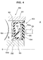
- Fig. 4 is a sectional view showing a conventional pulsar ring for a rotary encoder integrally provided in a sealing apparatus 100 for sealing a bearing portion of a wheel suspension apparatus for a motor vehicle by cutting it along a plane passing through an axis O.
- This kind of sealing apparatus 100 is also called as a hub seal, and is incorporated between end portions of an outer ring 201 and an inner ring 202 of a bearing 200 so as to prevent muddy water or the like from intruding into a bearing inner portion B from a bearing outer portion A.
- the sealing apparatus 100 shown in Fig. 4 is provided with a metal-made mounting ring 101 which is pressure-inserted and fitted to an inner peripheral surface of the outer ring 201 of the bearing 200, and a side lip 102 and a radial lip 103 which are integrally provided in the mounting ring 101, and the side lip 102 and the radial lip 103 are slidably brought into close contact with a slinger 104 tightly fitted to an outer peripheral surface of the inner ring 202.
- the side lip 102 and the radial lip 103 are made of a rubber-like elastic material, and are integrally adhered by vulcanization to the mounting ring 101 via a common base portion 104.
- the side lip 102 is structured such that a leading end is slidably brought into close contact with an inner side surface of a seal flange portion 104a of the slinger 104, and the radial lip 103 at an inner peripheral side thereof is structured such that an inner peripheral edge of a leading end directed to an outer side is slidably brought into close contact with an outer peripheral surface of a sleeve portion 104b of the slinger 104.
- a pulsar ring 105 is integrally provided on an outer side surface of the seal flange portion 104a of the slinger 104, and the pulsar ring 105 is formed by a magnetic rubber made by mixing a magnetic material to a rubber-like elastic material and is magnetized so as to be multipolar at a predetermined pitch in a circumferential direction. Further, a magnetic sensor 120 is arranged at an outer side of the pulsar ring 105 oppositely thereto in a non-rotating state.
- the magnetic sensor 120 constructs a rotary encoder together with the pulsar ring 105, and is structured such as to generate a pulse having a wave form corresponding to a change of a magnetic field caused by a rotation of the pulsar ring 105 together with the inner ring 202 of the bearing 200 and detect the rotation (refer to patent document 1).
- Patent Document 1 Japanese Unexamined Patent Publication No. 2004-93554
- the pulsar ring 105 made of the magnetic rubber is provided on the outer side surface of the seal flange portion 104a of the slinger 104, the pulsar ring 105 tends to be exposed to an external disturbance caused by a foreign matter, muddy water, an external magnetic field or the like from the bearing outer portion A. Accordingly, a reduction and a turbulence of magnetic force tend to occur, and it is hard to maintain a stable magnetic pattern.
- the present invention is made by taking the points mentioned above into consideration, and a technical object of the present invention is to make a magnetic field of a pulsar ring hard to be exposed to an external disturbance caused by a foreign matter, muddy water, an external magnetic field or the like from the outside, thereby maintaining a stable magnetic pattern.
- a pulsar ring for a rotary encoder comprising:
- a pulsar ring for a rotary encoder as recited in claim 1, wherein the pulsar ring further comprises a seal ring arranged in an inner side of the mounting ring, tightly fitted and fixed to one of the rotary side member, and the stationary side member and slidably brought into close contact with the other.
- a pulsar ring for a rotary encoder as recited in claim 2, wherein the pulsar ring main body is brought into close contact with the seal ring.
- the mounting ring is made of a non-magnetic material, it is possible to detect a magnetic field of the pulsar ring main body provided on the inner side surface of the mounting ring by a magnetic sensor arranged at the outer side of the mounting ring. Further, since a labyrinth seal effect can be achieved between the mounting ring and the stationary side member, the pulsar ring main body is protected by the mounting ring, and is hardly exposed to an external disturbance caused by a foreign matter, muddy water, an external magnetic field or the like in the outside, and it is possible to maintain a stable magnetic pattern.
- the seal ring is arranged in the inner side of the mounting ring, it is possible to preferably apply it for a hub seal with a rotary encoder for sealing a hub bearing in a vehicle, for example.
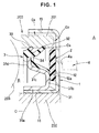
- Fig. 1 is a sectional view showing a pulsar ring for a rotary encoder in accordance with a first embodiment of the present invention by cutting it along a plane passing through an axis O
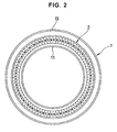
- Fig. 2 is an explanatory view showing one example of a magnetized pattern of a pulsar ring main body.
- reference numeral 200 denotes a bearing (a hub bearing) for rotatably supporting a wheel in a suspension apparatus of a motor vehicle.
- a lot of steel balls 203 are interposed between an outer ring 201 and an inner ring 202 arranged concentrically in an inner periphery of the outer ring 201.
- the outer ring 201 does not rotate and corresponds to a stationary side member described in claim 1
- the inner ring 202 rotates together with a shaft (not shown) and corresponds to a rotary side member described in claim 1.
- the pulsar ring for the rotary encoder in accordance with the present invention is provided with a mounting ring 1, a pulsar ring main body 2 integrally provided on an inner side surface of the mounting ring 1, and a seal ring 3 arranged in an inner side of the mounting ring 1.
- the mounting ring 1 is manufactured by a non-magnetic material such as an aluminum, a stainless steel, a synthetic resin or the like, is formed to have approximately a C-shape in a shape (an illustrated sectional shape) obtained by cutting it along a plane passing through an axis O, and is constituted by an inner peripheral tube portion 11 pressure-inserted and fitted to an outer peripheral surface of the inner ring 202, a radial portion 12 extending to an outer peripheral side from an end portion thereof at the bearing outer portion A side, and an outer peripheral tube portion 13 concentrically extending in such a manner as to cover an outer periphery of the outer ring 201 in the same direction as the inner peripheral tube portion 11 from an outer peripheral end portion of the radial portion 12 and being positioned in proximity to the outer ring 201 via an axial clearance G 1 and a radial clearance G 2 which are continuous with each other.
- the inner peripheral tube portion 11 corresponds to "one end” described in claim 1
- the outer peripheral tube portion 13 corresponds
- the pulsar ring main body 2 is vulcanized and thereby adhered to the inner side surface 12a of the radial portion 12 in the mounting ring 1, is made of a synthetic resin or a rubber-like elastic material mixed with magnetic powder which is one or more selected from a ferrite, a rare earth, an alnico and the like, and is a disc-shaped multipolar magnet in which south poles and north poles are alternately magnetized at a predetermined pitch in a circumferential direction, as shown in Fig. 2 .
- crank angle measuring reference point for detecting a specific position such as a top dead center of a piston of an engine, for example, or the like, can be set on the pulsar ring main body 2, by providing a portion (not shown) having a different magnetizing pitch at one position in the circumferential direction.
- an outer peripheral portion of the pulsar ring main body 2 is positioned in proximity to an inner peripheral surface of an end portion of the outer ring 201, and an annular clearance G 3 continuous with the radial clearance G 2 between the radial portion 12 of the mounting ring 1 and the outer ring 201 is formed between the both.
- the seal ring 3 is constituted by an inner ring 31 fitted and attached to the mounting ring 1, and seal lips 32 and 33 integrally provided on an outer peripheral portion of the inner ring 31 and slidably brought into close contact with an inner peripheral surface of the outer ring 201.
- the seal ring 3 is tightly fitted and fixed to the inner ring 202 at the rotary side with the inner ring 31 via the mounting ring 1.
- the inner ring 31 is manufactured by punching and pressing of a metal plate of a magnetic material, and is constituted by an inner peripheral tube portion 31a pressure-inserted and fitted to an outer peripheral surface of the inner peripheral tube portion 11 in the mounting ring 1, an inner peripheral radial portion 31b extending to an outer peripheral side from an end portion thereof at the bearing outer portion A side, a conical tube portion 31c extending from an outer peripheral end thereof toward a bearing inner portion B side so as to expand in diameter little by little, and an outer peripheral collar portion 31d extending to an outer peripheral side from a large-diameter end portion thereof.
- the inner peripheral radial portion 31b is brought into close contact with the inner peripheral portion of the pulsar ring main body 2.
- the seal lips 32 and 33 are integrally formed on the inner ring 31 by steps of positioning and setting the inner ring 31, to which a vulcanization adhesive agent is previously applied, in a predetermined metal mold, clamping the metal mold, filling a rubber molding material within a molding cavity defined between the metal mold and the inner ring 31, and heating and pressurizing the material, and a common base portion 34 is adhered by vulcanization to the conical tube portion 31c and the outer peripheral collar portion 31d of the inner ring 31.
- seal lips 32 and 33 extend from an outer peripheral end of the base portion 34 toward an opposite side to the bearing inner portion B so as to expand in conical tubular shapes, and outer peripheries of leading end portions of the seal lips 32 and 33 are slidably brought into close contact with the inner peripheral surface of the outer ring 201.
- Reference numeral 4 in Fig. 1 denotes a magnetic sensor.
- the magnetic sensor 4 is arranged at one position in a circumferential direction in the bearing outer portion A, and is fixed in a non-rotating state by a fixing member (not shown), and a detection surface 4a thereof is placed near to and is opposed to an outer side surface of the radial portion 12 in the mounting ring 1 in the axial direction.
- the mounting ring 1 is made of the non-magnetic material, a magnetic field corresponding to the magnetized pattern of the pulsar ring main body 2 provided on the inner side surface of the radial portion 12 runs to the outer side of the radial portion 12.
- Fig. 3 is a sectional view showing a pulsar ring for a rotary encoder in accordance with a second embodiment of the present invention by cutting it along a plane passing through an axis O.
- the pulsar ring is provided with the mounting ring 1, the pulsar ring main body 2 integrally provided on the inner side surface of the mounting ring 1, and the seal ring 3 arranged in the inner side of the mounting ring 1, similarly to the first embodiment mentioned above, and has a sectional shape symmetrical in a radial direction with the cross sectional shape shown in Fig. 1 .
- the outer ring 201 rotates together with a shaft (not shown), and corresponds to the rotary side member described in claim 1
- the inner ring 202 does not rotate, and corresponds to the stationary side member described in claim 1.
- the mounting ring 1 is manufactured by a non-magnetic material such as an aluminum, a stainless steel, a synthetic resin or the like, is formed to have approximately a C-shape in a shape (an illustrated cross sectional shape) obtained by cutting it along a plane passing through an axis O, and is constituted by an outer peripheral tube portion 14 pressure-inserted and fitted to an inner peripheral surface of the outer ring 201 at the rotary side, a radial portion 15 extending to an inner peripheral side from an end portion thereof at the bearing outer portion A side, and an inner peripheral tube portion 16 extending in the same direction as the outer peripheral tube portion 14 from an inner peripheral end portion of the radial portion 15 and being inserted to a tubular groove 202a formed in the non-rotating inner ring 202, to thereby form an inner peripheral side axial clearance G 4 , an outer peripheral side axial clearance G 5 and a radial clearance G 6 , which are continuous with each other, between the mounting ring 1 and the inner ring 202.
- the pulsar ring main body 2 is vulcanized and thereby adhered to an inner side surface 15a of the radial portion 15 in the mounting ring 1, is made of a synthetic resin or a rubber-like elastic material mixed with magnetic powder which is one or more selected from a ferrite, a rare earth, an alnico and the like, and is structured similarly to that of the first embodiment.
- an inner peripheral portion of the pulsar ring main body 2 is positioned in proximity to an outer peripheral surface of an end portion of the inner ring 202, and an annular clearance G 7 continuous with the radial clearance G 6 between the radial portion 15 of the mounting ring 1 and the inner ring 202 is formed between the both.
- the seal ring 3 is constituted by an inner ring 31 fitted and attached to the mounting ring 1, and seal lips 32 and 33 integrally provided on an inner peripheral portion of the inner ring 31 and slidably brought into close contact with an outer peripheral surface of the inner ring 202.
- the seal ring 3 is tightly fitted and fixed to the outer ring 201 at the rotary side with the inner ring 31 via the mounting ring 1.
- the inner ring 31 is manufactured by punching and pressing of a metal plate of a magnetic material, and is constituted by an outer peripheral tube portion 31e pressure-inserted and fitted to an inner peripheral surface of the outer peripheral tube portion 14 in the mounting ring 1, an outer peripheral radial portion 31f extending to an inner peripheral side from an end portion thereof at the bearing outer portion A side, a conical tube portion 31g extending from an inner peripheral end thereof toward a bearing inner portion B side so as to reduce in diameter little by little, and an inner peripheral collar portion 31h extending to an inner peripheral side from a small-diameter end portion thereof.
- the outer peripheral radial portion 31f is brought into close contact with the outer peripheral portion of the pulsar ring main body 2.
- the seal lips 32 and 33 are integrally formed on the inner ring 31 by steps of positioning and setting the inner ring 31, to which a vulcanization adhesive agent is previously applied, in a predetermined metal mold, clamping the metal mold, filling a rubber molding material within a molding cavity defined between the metal mold and the inner ring 31, and heating and pressurizing the material, and a common base portion 34 is adhered by vulcanization to the conical tube portion 31g and the inner peripheral collar portion 31h of the inner ring 31.
- seal lips 32 and 33 extend from an inner peripheral end of the base portion 34 toward an opposite side to the bearing inner portion B so as to narrow in conical tubular shapes, and inner peripheries of leading end portions of the seal lips 32 and 33 are slidably brought into close contact with the outer peripheral surface of the inner ring 202.
- the pulsar ring for the rotary encoder in Fig. 3 structured as mentioned above can basically achieve the same effect as that of Fig. 1 .
- the pulsar ring main body 2 is protected by the mounting ring 1, and is hardly exposed to an external disturbance, it is possible to maintain a stable magnetic pattern.
- the seal ring 3 can securely prevent them from intruding into the bearing inner portion B, and prevent grease from flowing out of the bearing inner portion B.
- the present invention relates to a pulsar ring utilized in a magnetic rotary encoder for detecting a rotation, and can provide the pulsar ring which can maintain a stable magnetic pattern.
Landscapes
- Engineering & Computer Science (AREA)
- General Engineering & Computer Science (AREA)
- Mechanical Engineering (AREA)
- Physics & Mathematics (AREA)
- General Physics & Mathematics (AREA)
- Transmission And Conversion Of Sensor Element Output (AREA)
- Sealing Of Bearings (AREA)
Abstract
Description
- The present invention relates to a pulsar ring of a magnetic rotary encoder for detecting a rotation.
-
Fig. 4 is a sectional view showing a conventional pulsar ring for a rotary encoder integrally provided in asealing apparatus 100 for sealing a bearing portion of a wheel suspension apparatus for a motor vehicle by cutting it along a plane passing through an axis O. This kind of sealingapparatus 100 is also called as a hub seal, and is incorporated between end portions of anouter ring 201 and aninner ring 202 of a bearing 200 so as to prevent muddy water or the like from intruding into a bearing inner portion B from a bearing outer portion A. - In particular, the
sealing apparatus 100 shown inFig. 4 is provided with a metal-mademounting ring 101 which is pressure-inserted and fitted to an inner peripheral surface of theouter ring 201 of thebearing 200, and aside lip 102 and aradial lip 103 which are integrally provided in themounting ring 101, and theside lip 102 and theradial lip 103 are slidably brought into close contact with aslinger 104 tightly fitted to an outer peripheral surface of theinner ring 202. In detail, theside lip 102 and theradial lip 103 are made of a rubber-like elastic material, and are integrally adhered by vulcanization to themounting ring 101 via acommon base portion 104. Theside lip 102 is structured such that a leading end is slidably brought into close contact with an inner side surface of aseal flange portion 104a of theslinger 104, and theradial lip 103 at an inner peripheral side thereof is structured such that an inner peripheral edge of a leading end directed to an outer side is slidably brought into close contact with an outer peripheral surface of asleeve portion 104b of theslinger 104. - A
pulsar ring 105 is integrally provided on an outer side surface of theseal flange portion 104a of theslinger 104, and thepulsar ring 105 is formed by a magnetic rubber made by mixing a magnetic material to a rubber-like elastic material and is magnetized so as to be multipolar at a predetermined pitch in a circumferential direction. Further, amagnetic sensor 120 is arranged at an outer side of thepulsar ring 105 oppositely thereto in a non-rotating state. - The
magnetic sensor 120 constructs a rotary encoder together with thepulsar ring 105, and is structured such as to generate a pulse having a wave form corresponding to a change of a magnetic field caused by a rotation of thepulsar ring 105 together with theinner ring 202 of thebearing 200 and detect the rotation (refer to patent document 1). - Patent Document 1: Japanese Unexamined Patent Publication No.
2004-93554 - However, conventionally, since the
pulsar ring 105 made of the magnetic rubber is provided on the outer side surface of theseal flange portion 104a of theslinger 104, thepulsar ring 105 tends to be exposed to an external disturbance caused by a foreign matter, muddy water, an external magnetic field or the like from the bearing outer portion A. Accordingly, a reduction and a turbulence of magnetic force tend to occur, and it is hard to maintain a stable magnetic pattern. - The present invention is made by taking the points mentioned above into consideration, and a technical object of the present invention is to make a magnetic field of a pulsar ring hard to be exposed to an external disturbance caused by a foreign matter, muddy water, an external magnetic field or the like from the outside, thereby maintaining a stable magnetic pattern.
- As a means for effectively solving the technical problem mentioned above, in accordance with
claim 1 of the present invention, there is provided a pulsar ring for a rotary encoder, comprising: - a mounting ring made of a non-magnetic material, with one end being tightly fitted and fixed to a rotary side member and the other end being positioned in proximity to a stationary side member via a labyrinth-shaped clearance; and
- a pulsar ring main body formed by a synthetic resin or a rubber-like elastic material mixed with magnetic powder, magnetized so as to have multiple poles and integrally provided on an inner side surface of the mounting ring.
- Further, in accordance with
claim 2 of the present invention, there is provided a pulsar ring for a rotary encoder as recited inclaim 1, wherein the pulsar ring further comprises a seal ring arranged in an inner side of the mounting ring, tightly fitted and fixed to one of the rotary side member, and the stationary side member and slidably brought into close contact with the other. - Further, in accordance with
claim 3 of the present invention, there is provided a pulsar ring for a rotary encoder as recited inclaim 2, wherein the pulsar ring main body is brought into close contact with the seal ring. - In accordance with the pulsar ring for the rotary encoder on the basis of
claim 1 of the present invention, since the mounting ring is made of a non-magnetic material, it is possible to detect a magnetic field of the pulsar ring main body provided on the inner side surface of the mounting ring by a magnetic sensor arranged at the outer side of the mounting ring. Further, since a labyrinth seal effect can be achieved between the mounting ring and the stationary side member, the pulsar ring main body is protected by the mounting ring, and is hardly exposed to an external disturbance caused by a foreign matter, muddy water, an external magnetic field or the like in the outside, and it is possible to maintain a stable magnetic pattern. - In accordance with the pulsar ring for the rotary encoder on the basis of
claim 2 of the present invention, since the seal ring is arranged in the inner side of the mounting ring, it is possible to preferably apply it for a hub seal with a rotary encoder for sealing a hub bearing in a vehicle, for example. - In accordance with the pulsar ring for the rotary encoder on the basis of
claim 3 of the present invention, since a seal function is given also to the pulsar ring main body, it is possible to further increase a sealing function obtainable by the seal ring inclaim 2. -
-
Fig. 1 is a sectional view showing a pulsar ring for a rotary encoder in accordance with a first embodiment of the present invention by cutting it along a plane passing through an axis O; -
Fig. 2 is an explanatory view showing one example of a magnetized pattern of a pulsar ring main body; -
Fig. 3 is a sectional view showing a pulsar ring for a rotary encoder in accordance with a second embodiment of the present invention by cutting it along a plane passing through an axis O; and -
Fig. 4 is a sectional view showing a conventional pulsar ring for a rotary encoder integrally provided in a sealing apparatus by cutting it along a plane passing through an axis O. -
- 1
- mounting ring
- 2
- pulsar ring main body
- 3
- seal ring
- 31
- inner ring
- 32,
- 33 seal lip
- 4
- magnetic sensor
- 200
- bearing
- 201
- outer ring
- 202
- inner ring
- G1
- axial clearance
- G2,
- G6 radial clearance
- G3,
- G7 annular clearance
- G4
- inner peripheral side axial clearance
- G5
- outer peripheral side axial clearance
- A description will be given below of a preferable embodiment of a pulsar ring for a rotary encoder in accordance with the present invention with reference to the accompanying drawings.
Fig. 1 is a sectional view showing a pulsar ring for a rotary encoder in accordance with a first embodiment of the present invention by cutting it along a plane passing through an axis O, andFig. 2 is an explanatory view showing one example of a magnetized pattern of a pulsar ring main body. - In
Fig. 1 ,reference numeral 200 denotes a bearing (a hub bearing) for rotatably supporting a wheel in a suspension apparatus of a motor vehicle. A lot ofsteel balls 203 are interposed between anouter ring 201 and aninner ring 202 arranged concentrically in an inner periphery of theouter ring 201. In this case, theouter ring 201 does not rotate and corresponds to a stationary side member described inclaim 1, and theinner ring 202 rotates together with a shaft (not shown) and corresponds to a rotary side member described inclaim 1. - As shown in
Fig. 1 , the pulsar ring for the rotary encoder in accordance with the present invention is provided with a mountingring 1, a pulsar ringmain body 2 integrally provided on an inner side surface of the mountingring 1, and aseal ring 3 arranged in an inner side of the mountingring 1. - In detail, the mounting
ring 1 is manufactured by a non-magnetic material such as an aluminum, a stainless steel, a synthetic resin or the like, is formed to have approximately a C-shape in a shape (an illustrated sectional shape) obtained by cutting it along a plane passing through an axis O, and is constituted by an innerperipheral tube portion 11 pressure-inserted and fitted to an outer peripheral surface of theinner ring 202, aradial portion 12 extending to an outer peripheral side from an end portion thereof at the bearing outer portion A side, and an outerperipheral tube portion 13 concentrically extending in such a manner as to cover an outer periphery of theouter ring 201 in the same direction as the innerperipheral tube portion 11 from an outer peripheral end portion of theradial portion 12 and being positioned in proximity to theouter ring 201 via an axial clearance G1 and a radial clearance G2 which are continuous with each other. In this embodiment, the innerperipheral tube portion 11 corresponds to "one end" described inclaim 1, and the outerperipheral tube portion 13 corresponds to "the other end" described inclaim 1. - The pulsar ring
main body 2 is vulcanized and thereby adhered to theinner side surface 12a of theradial portion 12 in the mountingring 1, is made of a synthetic resin or a rubber-like elastic material mixed with magnetic powder which is one or more selected from a ferrite, a rare earth, an alnico and the like, and is a disc-shaped multipolar magnet in which south poles and north poles are alternately magnetized at a predetermined pitch in a circumferential direction, as shown inFig. 2 . Further, a crank angle measuring reference point (not shown) for detecting a specific position such as a top dead center of a piston of an engine, for example, or the like, can be set on the pulsar ringmain body 2, by providing a portion (not shown) having a different magnetizing pitch at one position in the circumferential direction. - Further, an outer peripheral portion of the pulsar ring
main body 2 is positioned in proximity to an inner peripheral surface of an end portion of theouter ring 201, and an annular clearance G3 continuous with the radial clearance G2 between theradial portion 12 of the mountingring 1 and theouter ring 201 is formed between the both. - The
seal ring 3 is constituted by aninner ring 31 fitted and attached to the mountingring 1, and seallips inner ring 31 and slidably brought into close contact with an inner peripheral surface of theouter ring 201. In other words, theseal ring 3 is tightly fitted and fixed to theinner ring 202 at the rotary side with theinner ring 31 via the mountingring 1. - In detail, the
inner ring 31 is manufactured by punching and pressing of a metal plate of a magnetic material, and is constituted by an innerperipheral tube portion 31a pressure-inserted and fitted to an outer peripheral surface of the innerperipheral tube portion 11 in the mountingring 1, an inner peripheralradial portion 31b extending to an outer peripheral side from an end portion thereof at the bearing outer portion A side, aconical tube portion 31c extending from an outer peripheral end thereof toward a bearing inner portion B side so as to expand in diameter little by little, and an outerperipheral collar portion 31d extending to an outer peripheral side from a large-diameter end portion thereof. The inner peripheralradial portion 31b is brought into close contact with the inner peripheral portion of the pulsar ringmain body 2. - The
seal lips inner ring 31 by steps of positioning and setting theinner ring 31, to which a vulcanization adhesive agent is previously applied, in a predetermined metal mold, clamping the metal mold, filling a rubber molding material within a molding cavity defined between the metal mold and theinner ring 31, and heating and pressurizing the material, and acommon base portion 34 is adhered by vulcanization to theconical tube portion 31c and the outerperipheral collar portion 31d of theinner ring 31. Further, theseal lips base portion 34 toward an opposite side to the bearing inner portion B so as to expand in conical tubular shapes, and outer peripheries of leading end portions of theseal lips outer ring 201. -
Reference numeral 4 inFig. 1 denotes a magnetic sensor. Themagnetic sensor 4 is arranged at one position in a circumferential direction in the bearing outer portion A, and is fixed in a non-rotating state by a fixing member (not shown), and adetection surface 4a thereof is placed near to and is opposed to an outer side surface of theradial portion 12 in the mountingring 1 in the axial direction. - According to the structure mentioned above of the pulsar ring for the rotary encoder of the present invention, since the mounting
ring 1 is made of the non-magnetic material, a magnetic field corresponding to the magnetized pattern of the pulsar ringmain body 2 provided on the inner side surface of theradial portion 12 runs to the outer side of theradial portion 12. Therefore, since the mountingring 1 and the pulsar ringmain body 2 integrally formed therewith rotate together with theinner ring 202 of thebearing 200, whereby the north poles and the south poles alternately pass through the front of thedetection surface 4a of themagnetic sensor 4 in a rotating direction, a pulse-shaped signal having a wave form corresponding to a change of the magnetic field is output from themagnetic sensor 4, whereby it is possible to measure a rotation angle and a rotation speed. - In this case, soil dust, a foreign matter, muddy water and the like fly to the bearing outer portion A in consequence of traveling of a vehicle, however, the axial clearance G1, the radial clearance G2 and the annular clearance G3, which are continuous with each other, are formed in a labyrinth shape between the mounting
ring 1 and the pulsar ringmain body 2 rotating together with theinner ring 202, and the non-rotatingouter ring 201, a labyrinth seal effect is achieved by the rotation, and the soil dust, the foreign matter and the muddy water in the bearing outer portion A can not easily intrude into the inner side of the mountingring 1. Accordingly, since the pulsar ringmain body 2 is protected by the mountingring 1, and is hardly exposed to an external disturbance, it is possible to maintain a stable magnetic pattern. - On the other hand, since the
inner ring 31 of theseal ring 3 is integrally fitted and attached to the mountingring 1, theseal ring 3 is rotated together with theinner ring 202 of thebearing 200 via the mountingring 1, and theseal lips outer ring 201 so as to slide, thereby achieving a sealing function. Accordingly, even if muddy water, soil dust or the like slightly intrudes into the inner side of the mountingring 1 through the axial clearance G1, the radial clearance G2 and the annular clearance G3 which are continuous with each other, it is possible to securely prevent them from intruding into the bearing inner portion B, and it is possible to prevent grease from flowing out of the bearing inner portion B. - Further, since the inner peripheral
radial portion 31b of theinner ring 31 in theseal ring 3 is brought into close contact with the inner peripheral portion of the pulsar ringmain body 2, muddy water, soil dust or the like slightly intruded into the inner side of the mountingring 1 does not intrude into the bearing inner portion B from the fitting portion between the innerperipheral tube portion 11 of the mountingring 1 and the innerperipheral tube portion 31a of theinner ring 31. - Next,
Fig. 3 is a sectional view showing a pulsar ring for a rotary encoder in accordance with a second embodiment of the present invention by cutting it along a plane passing through an axis O. The pulsar ring is provided with the mountingring 1, the pulsar ringmain body 2 integrally provided on the inner side surface of the mountingring 1, and theseal ring 3 arranged in the inner side of the mountingring 1, similarly to the first embodiment mentioned above, and has a sectional shape symmetrical in a radial direction with the cross sectional shape shown inFig. 1 . Further, in this embodiment, theouter ring 201 rotates together with a shaft (not shown), and corresponds to the rotary side member described inclaim 1, and theinner ring 202 does not rotate, and corresponds to the stationary side member described inclaim 1. - In detail, the mounting
ring 1 is manufactured by a non-magnetic material such as an aluminum, a stainless steel, a synthetic resin or the like, is formed to have approximately a C-shape in a shape (an illustrated cross sectional shape) obtained by cutting it along a plane passing through an axis O, and is constituted by an outerperipheral tube portion 14 pressure-inserted and fitted to an inner peripheral surface of theouter ring 201 at the rotary side, aradial portion 15 extending to an inner peripheral side from an end portion thereof at the bearing outer portion A side, and an innerperipheral tube portion 16 extending in the same direction as the outerperipheral tube portion 14 from an inner peripheral end portion of theradial portion 15 and being inserted to atubular groove 202a formed in the non-rotatinginner ring 202, to thereby form an inner peripheral side axial clearance G4, an outer peripheral side axial clearance G5 and a radial clearance G6, which are continuous with each other, between the mountingring 1 and theinner ring 202. In this embodiment, the outerperipheral tube portion 14 corresponds to "one end" described inclaim 1, and the innerperipheral tube portion 16 corresponds to "the other end" described inclaim 1. - The pulsar ring
main body 2 is vulcanized and thereby adhered to aninner side surface 15a of theradial portion 15 in the mountingring 1, is made of a synthetic resin or a rubber-like elastic material mixed with magnetic powder which is one or more selected from a ferrite, a rare earth, an alnico and the like, and is structured similarly to that of the first embodiment. - Further, an inner peripheral portion of the pulsar ring
main body 2 is positioned in proximity to an outer peripheral surface of an end portion of theinner ring 202, and an annular clearance G7 continuous with the radial clearance G6 between theradial portion 15 of the mountingring 1 and theinner ring 202 is formed between the both. - The
seal ring 3 is constituted by aninner ring 31 fitted and attached to the mountingring 1, and seallips inner ring 31 and slidably brought into close contact with an outer peripheral surface of theinner ring 202. In other words, theseal ring 3 is tightly fitted and fixed to theouter ring 201 at the rotary side with theinner ring 31 via the mountingring 1. - In detail, the
inner ring 31 is manufactured by punching and pressing of a metal plate of a magnetic material, and is constituted by an outerperipheral tube portion 31e pressure-inserted and fitted to an inner peripheral surface of the outerperipheral tube portion 14 in the mountingring 1, an outer peripheralradial portion 31f extending to an inner peripheral side from an end portion thereof at the bearing outer portion A side, aconical tube portion 31g extending from an inner peripheral end thereof toward a bearing inner portion B side so as to reduce in diameter little by little, and an innerperipheral collar portion 31h extending to an inner peripheral side from a small-diameter end portion thereof. The outer peripheralradial portion 31f is brought into close contact with the outer peripheral portion of the pulsar ringmain body 2. - The
seal lips inner ring 31 by steps of positioning and setting theinner ring 31, to which a vulcanization adhesive agent is previously applied, in a predetermined metal mold, clamping the metal mold, filling a rubber molding material within a molding cavity defined between the metal mold and theinner ring 31, and heating and pressurizing the material, and acommon base portion 34 is adhered by vulcanization to theconical tube portion 31g and the innerperipheral collar portion 31h of theinner ring 31. Further, theseal lips base portion 34 toward an opposite side to the bearing inner portion B so as to narrow in conical tubular shapes, and inner peripheries of leading end portions of theseal lips inner ring 202. - The pulsar ring for the rotary encoder in
Fig. 3 structured as mentioned above can basically achieve the same effect as that ofFig. 1 . In other words, since the pulsar ringmain body 2 is protected by the mountingring 1, and is hardly exposed to an external disturbance, it is possible to maintain a stable magnetic pattern. Further, even if muddy water, soil dust or the like slightly intrudes into the inner side of the mountingring 1, theseal ring 3 can securely prevent them from intruding into the bearing inner portion B, and prevent grease from flowing out of the bearing inner portion B. - Further, since the inner
peripheral tube portion 16 of the mountingring 1 is inserted to thetubular groove 202a formed in theinner ring 202, whereby the long axial clearances G4 and G5 are formed in a shape of being folded back in the axial direction, it is possible to increase a labyrinth seal effect on the basis of a more complicated labyrinth shape than that ofFig. 1 . - The present invention relates to a pulsar ring utilized in a magnetic rotary encoder for detecting a rotation, and can provide the pulsar ring which can maintain a stable magnetic pattern.
Claims (3)
- A pulsar ring for a rotary encoder, comprising:a mounting ring (1) made of a non-magnetic material, with one end being tightly fitted and fixed to a rotary side member and the other end being positioned in proximity to a stationary side member via a labyrinth-shaped clearance; anda pulsar ring main body (2) formed by a synthetic resin or a rubber-like elastic material mixed with magnetic powder, magnetized so as to have multiple poles and integrally provided on an inner side surface of said mounting ring (1).
- A pulsar ring for a rotary encoder as claimed in claim 1, wherein the pulsar ring further comprises a seal ring (3) arranged in an inner side of the mounting ring (1), tightly fitted and fixed to one of the rotary side member, and the stationary side member and slidably brought into close contact with the other.
- A pulsar ring for a rotary encoder as claimed in claim 1, wherein the pulsar ring main body (2) is brought into close contact with the seal ring (3).
Applications Claiming Priority (2)
| Application Number | Priority Date | Filing Date | Title |
|---|---|---|---|
| JP2006098357A JP4780314B2 (en) | 2006-03-31 | 2006-03-31 | Pulsar ring for rotary encoder |
| PCT/JP2007/055175 WO2007114019A1 (en) | 2006-03-31 | 2007-03-15 | Pulser ring for rotary encoder |
Publications (2)
| Publication Number | Publication Date |
|---|---|
| EP2003425A1 true EP2003425A1 (en) | 2008-12-17 |
| EP2003425A4 EP2003425A4 (en) | 2013-12-11 |
Family
ID=38563289
Family Applications (1)
| Application Number | Title | Priority Date | Filing Date |
|---|---|---|---|
| EP20070738625 Withdrawn EP2003425A4 (en) | 2006-03-31 | 2007-03-15 | Pulser ring for rotary encoder |
Country Status (6)
| Country | Link |
|---|---|
| US (1) | US7960967B2 (en) |
| EP (1) | EP2003425A4 (en) |
| JP (1) | JP4780314B2 (en) |
| KR (1) | KR101340279B1 (en) |
| CN (1) | CN101416030B (en) |
| WO (1) | WO2007114019A1 (en) |
Cited By (2)
| Publication number | Priority date | Publication date | Assignee | Title |
|---|---|---|---|---|
| FR3001509A1 (en) * | 2013-01-28 | 2014-08-01 | Ntn Snr Roulements | Rolling bearing for drive system for rotating wheel of car, has outer element equipped with deflector laterally covering encoder, where deflector extends between fixing and sealing edges opposite sealing wall of inner element |
| WO2015010735A1 (en) * | 2013-07-24 | 2015-01-29 | Aktiebolaget Skf | Sensor-bearing unit, mechanical system comprising at least one such unit and mounting method |
Families Citing this family (10)
| Publication number | Priority date | Publication date | Assignee | Title |
|---|---|---|---|---|
| JP2009197975A (en) * | 2008-02-25 | 2009-09-03 | Jtekt Corp | Bearing apparatus for axle |
| US8947076B2 (en) | 2010-01-18 | 2015-02-03 | Bourns, Inc. | High resolution non-contacting multi-turn position sensor |
| DE102010064145A1 (en) * | 2010-08-03 | 2012-02-09 | Continental Teves Ag & Co. Ohg | Torque sensor arrangement with index magnet |
| DE102011078281A1 (en) * | 2010-08-04 | 2012-02-09 | Continental Teves Ag & Co. Ohg | Sensor arrangement with magnetic index encoder in a bearing seal |
| KR101573020B1 (en) * | 2014-02-28 | 2015-12-11 | 주식회사 일진글로벌 | Wheel bearing mounted with encoder |
| ITUB20151194A1 (en) * | 2015-05-29 | 2016-11-29 | Skf Ab | ROLLING BEARING INCLUDING A LOW FRICTION SEALING DEVICE, ESPECIALLY FOR A WHEEL HUB ASSEMBLY. |
| JP6765186B2 (en) * | 2015-12-08 | 2020-10-07 | 内山工業株式会社 | Sealing device |
| DE102016222110A1 (en) * | 2016-11-10 | 2017-03-16 | Audi Ag | Wheel bearing arrangement for a motor vehicle |
| CN111927890A (en) * | 2020-08-11 | 2020-11-13 | 瓦房店冶金轴承集团有限公司 | Novel contact type sealing ring and rolling mill supporting roller bearing applying same |
| CN117515022A (en) * | 2023-11-09 | 2024-02-06 | 人本股份有限公司 | Wheel hub bearings that facilitate the integration of ABS functions |
Family Cites Families (12)
| Publication number | Priority date | Publication date | Assignee | Title |
|---|---|---|---|---|
| FR2730566B1 (en) * | 1995-02-09 | 1997-06-13 | Skf France | ENCODER DEVICE FOR ROTATION SPEED SENSOR AND BEARING PROVIDED WITH SUCH A DEVICE |
| DE19644744C2 (en) * | 1996-10-28 | 2002-05-02 | Fag Automobiltechnik Ag | Speed measuring device for wheel bearings |
| JPH11174068A (en) * | 1997-12-10 | 1999-07-02 | Nippon Seiko Kk | Rolling bearing unit with encoder |
| JP2002081452A (en) * | 2000-09-04 | 2002-03-22 | Ntn Corp | Bearing device for driven wheel |
| US6692153B2 (en) * | 2001-03-07 | 2004-02-17 | Ntn Corporation | Wheel support bearing assembly |
| DE10225959A1 (en) | 2002-06-11 | 2004-01-08 | Carl Freudenberg Kg | Device for sealing the gap between a stationary housing and a rotating shaft |
| ITTO20030134A1 (en) * | 2003-02-25 | 2004-08-26 | Skf Ind Spa | PROTECTION DEVICE OF A PHONIC WHEEL IN A BEARING |
| JP2005009671A (en) * | 2003-05-26 | 2005-01-13 | Ntn Corp | Bearing with rotary sensor |
| JP4300412B2 (en) * | 2003-07-22 | 2009-07-22 | Nok株式会社 | Sealing device with encoder |
| JP4411911B2 (en) * | 2003-09-10 | 2010-02-10 | Nok株式会社 | Sealing device |
| US7618194B2 (en) * | 2004-04-09 | 2009-11-17 | Ntn Corporation | Wheel bearing apparatus incorporated with a wheel speed detecting apparatus |
| US7232129B2 (en) * | 2004-10-12 | 2007-06-19 | Nok Corporation | Sealing apparatus with encoder |
-
2006
- 2006-03-31 JP JP2006098357A patent/JP4780314B2/en not_active Expired - Fee Related
-
2007
- 2007-03-15 WO PCT/JP2007/055175 patent/WO2007114019A1/en not_active Ceased
- 2007-03-15 KR KR1020087024497A patent/KR101340279B1/en not_active Expired - Fee Related
- 2007-03-15 CN CN2007800118266A patent/CN101416030B/en not_active Expired - Fee Related
- 2007-03-15 US US12/225,495 patent/US7960967B2/en not_active Expired - Fee Related
- 2007-03-15 EP EP20070738625 patent/EP2003425A4/en not_active Withdrawn
Cited By (2)
| Publication number | Priority date | Publication date | Assignee | Title |
|---|---|---|---|---|
| FR3001509A1 (en) * | 2013-01-28 | 2014-08-01 | Ntn Snr Roulements | Rolling bearing for drive system for rotating wheel of car, has outer element equipped with deflector laterally covering encoder, where deflector extends between fixing and sealing edges opposite sealing wall of inner element |
| WO2015010735A1 (en) * | 2013-07-24 | 2015-01-29 | Aktiebolaget Skf | Sensor-bearing unit, mechanical system comprising at least one such unit and mounting method |
Also Published As
| Publication number | Publication date |
|---|---|
| KR20080108276A (en) | 2008-12-12 |
| JP4780314B2 (en) | 2011-09-28 |
| CN101416030A (en) | 2009-04-22 |
| WO2007114019A1 (en) | 2007-10-11 |
| US7960967B2 (en) | 2011-06-14 |
| JP2007271488A (en) | 2007-10-18 |
| EP2003425A4 (en) | 2013-12-11 |
| KR101340279B1 (en) | 2013-12-10 |
| US20090153136A1 (en) | 2009-06-18 |
| CN101416030B (en) | 2012-10-17 |
Similar Documents
| Publication | Publication Date | Title |
|---|---|---|
| US7960967B2 (en) | Sealing ring with a pulsar ring for a rotary encoder | |
| US8087673B2 (en) | Sealing device | |
| US6605938B1 (en) | Compact wheel speed detector capable of saving space and improving workability | |
| US7464939B2 (en) | Sealing device with rotation detecting element | |
| JPH11257998A5 (en) | ||
| JP2005083537A (en) | Sealing device | |
| JPWO2018110626A1 (en) | Sealing device | |
| JPWO2003012456A1 (en) | Rotor for rotation sensor | |
| JP2001241435A (en) | Rolling bearing unit with automotive encoder | |
| JPH11303879A (en) | Bearing seal | |
| JP2005114507A (en) | Encoder having cylindrical cover | |
| WO2012063506A1 (en) | Sealing device | |
| JP2006064066A (en) | Sealing device with rotary encoder | |
| JP2009047562A (en) | Pulser ring for magnetic encoder | |
| US20080150238A1 (en) | Hermetically Sealing Device With Magnetic Encoder | |
| JP3484473B2 (en) | Bearing seal | |
| EP1764534A2 (en) | Integrated unit having an encoder and a seal for a rolling bearing | |
| JP4924821B2 (en) | Pulsar ring of magnetic rotary encoder | |
| JP2004233221A (en) | Tone wheel with protective covering | |
| JP2009030620A (en) | Hermetically sealing device | |
| JP2009264416A (en) | Sealing device | |
| JP2005024017A (en) | Structure of bearing device with tone wheel | |
| JP2009019741A (en) | Hermetically sealing device with magnetic encoder | |
| JP2006233991A (en) | Sealing device |
Legal Events
| Date | Code | Title | Description |
|---|---|---|---|
| PUAI | Public reference made under article 153(3) epc to a published international application that has entered the european phase |
Free format text: ORIGINAL CODE: 0009012 |
|
| 17P | Request for examination filed |
Effective date: 20080924 |
|
| AK | Designated contracting states |
Kind code of ref document: A1 Designated state(s): DE FR GB |
|
| DAX | Request for extension of the european patent (deleted) | ||
| RBV | Designated contracting states (corrected) |
Designated state(s): DE FR GB |
|
| RIN1 | Information on inventor provided before grant (corrected) |
Inventor name: KOBAYASHI, NAOTO |
|
| A4 | Supplementary search report drawn up and despatched |
Effective date: 20131111 |
|
| RIC1 | Information provided on ipc code assigned before grant |
Ipc: F16C 33/78 20060101ALI20131105BHEP Ipc: F16C 41/00 20060101ALI20131105BHEP Ipc: G01P 3/44 20060101ALI20131105BHEP Ipc: G01D 5/245 20060101AFI20131105BHEP |
|
| 17Q | First examination report despatched |
Effective date: 20151201 |
|
| STAA | Information on the status of an ep patent application or granted ep patent |
Free format text: STATUS: THE APPLICATION IS DEEMED TO BE WITHDRAWN |
|
| 18D | Application deemed to be withdrawn |
Effective date: 20160412 |