EP2003398A2 - Fuel nozzle providing shaped fuel spray - Google Patents
Fuel nozzle providing shaped fuel spray Download PDFInfo
- Publication number
- EP2003398A2 EP2003398A2 EP08252061A EP08252061A EP2003398A2 EP 2003398 A2 EP2003398 A2 EP 2003398A2 EP 08252061 A EP08252061 A EP 08252061A EP 08252061 A EP08252061 A EP 08252061A EP 2003398 A2 EP2003398 A2 EP 2003398A2
- Authority
- EP
- European Patent Office
- Prior art keywords
- fuel
- spray
- nozzle
- airflow passages
- series
- Prior art date
- Legal status (The legal status is an assumption and is not a legal conclusion. Google has not performed a legal analysis and makes no representation as to the accuracy of the status listed.)
- Granted
Links
- 239000000446 fuel Substances 0.000 title claims abstract description 275
- 239000007921 spray Substances 0.000 title claims abstract description 162
- 238000007493 shaping process Methods 0.000 claims abstract description 25
- 238000002347 injection Methods 0.000 claims abstract description 9
- 239000007924 injection Substances 0.000 claims abstract description 9
- 238000002485 combustion reaction Methods 0.000 claims description 12
- 238000004891 communication Methods 0.000 claims description 7
- 239000000203 mixture Substances 0.000 claims description 5
- 239000012530 fluid Substances 0.000 claims description 3
- 238000009718 spray deposition Methods 0.000 abstract 1
- 239000003570 air Substances 0.000 description 35
- 239000007789 gas Substances 0.000 description 16
- 238000012986 modification Methods 0.000 description 3
- 230000004048 modification Effects 0.000 description 3
- 238000000889 atomisation Methods 0.000 description 2
- 239000000567 combustion gas Substances 0.000 description 2
- 238000010276 construction Methods 0.000 description 2
- 238000004519 manufacturing process Methods 0.000 description 2
- 239000012080 ambient air Substances 0.000 description 1
- 230000000694 effects Effects 0.000 description 1
- 239000011369 resultant mixture Substances 0.000 description 1
- 238000011144 upstream manufacturing Methods 0.000 description 1
Images


Classifications
-
- F—MECHANICAL ENGINEERING; LIGHTING; HEATING; WEAPONS; BLASTING
- F23—COMBUSTION APPARATUS; COMBUSTION PROCESSES
- F23D—BURNERS
- F23D11/00—Burners using a direct spraying action of liquid droplets or vaporised liquid into the combustion space
- F23D11/24—Burners using a direct spraying action of liquid droplets or vaporised liquid into the combustion space by pressurisation of the fuel before a nozzle through which it is sprayed by a substantial pressure reduction into a space
-
- F—MECHANICAL ENGINEERING; LIGHTING; HEATING; WEAPONS; BLASTING
- F23—COMBUSTION APPARATUS; COMBUSTION PROCESSES
- F23D—BURNERS
- F23D11/00—Burners using a direct spraying action of liquid droplets or vaporised liquid into the combustion space
- F23D11/10—Burners using a direct spraying action of liquid droplets or vaporised liquid into the combustion space the spraying being induced by a gaseous medium, e.g. water vapour
- F23D11/108—Burners using a direct spraying action of liquid droplets or vaporised liquid into the combustion space the spraying being induced by a gaseous medium, e.g. water vapour medium and fuel intersecting downstream of the burner outlet
-
- F—MECHANICAL ENGINEERING; LIGHTING; HEATING; WEAPONS; BLASTING
- F23—COMBUSTION APPARATUS; COMBUSTION PROCESSES
- F23D—BURNERS
- F23D11/00—Burners using a direct spraying action of liquid droplets or vaporised liquid into the combustion space
- F23D11/10—Burners using a direct spraying action of liquid droplets or vaporised liquid into the combustion space the spraying being induced by a gaseous medium, e.g. water vapour
- F23D11/12—Burners using a direct spraying action of liquid droplets or vaporised liquid into the combustion space the spraying being induced by a gaseous medium, e.g. water vapour characterised by the shape or arrangement of the outlets from the nozzle
-
- F—MECHANICAL ENGINEERING; LIGHTING; HEATING; WEAPONS; BLASTING
- F23—COMBUSTION APPARATUS; COMBUSTION PROCESSES
- F23R—GENERATING COMBUSTION PRODUCTS OF HIGH PRESSURE OR HIGH VELOCITY, e.g. GAS-TURBINE COMBUSTION CHAMBERS
- F23R3/00—Continuous combustion chambers using liquid or gaseous fuel
- F23R3/02—Continuous combustion chambers using liquid or gaseous fuel characterised by the air-flow or gas-flow configuration
- F23R3/04—Air inlet arrangements
- F23R3/10—Air inlet arrangements for primary air
-
- F—MECHANICAL ENGINEERING; LIGHTING; HEATING; WEAPONS; BLASTING
- F23—COMBUSTION APPARATUS; COMBUSTION PROCESSES
- F23R—GENERATING COMBUSTION PRODUCTS OF HIGH PRESSURE OR HIGH VELOCITY, e.g. GAS-TURBINE COMBUSTION CHAMBERS
- F23R3/00—Continuous combustion chambers using liquid or gaseous fuel
- F23R3/28—Continuous combustion chambers using liquid or gaseous fuel characterised by the fuel supply
Definitions
- the invention relates generally to gas turbine engines and, more particularly, to fuel nozzles for such engines.
- Gas turbine engine combustors employ a plurality of fuel nozzles, typically arranged in an annular configuration, to spray the fuel into the combustion chamber of an annular combustor.
- Each of these fuel nozzles generates a spray of fuel which is generally conical in shape and which defines a generally circular cross-sectional profile, as shown in Fig. 6b for example.
- a relatively large number of fuel nozzles are required about the combustor.
- the present invention provides a fuel nozzle for use in a combustor of a gas turbine engine, the fuel nozzle comprising: a nozzle body defining at least one fuel flow passage therethrough; a spray tip mounted to the nozzle body, the spray tip having a central fuel ejection nozzle in flow communication with the at least one fuel flow passage and defining a fuel spray axis, the central fuel ejection nozzle ejecting fuel out of the spray tip in an initially conical fuel spray about the fuel spray axis; at least a first series of airflow passages disposed in said spray tip radially outwardly from the central fuel ejection nozzle, said first series of airflow passages including opposed groups of airflow passages, said opposed groups of airflow passages being circumferentially spaced apart and located on opposite sides of a transverse axis extending through said central fuel ejection nozzle perpendicularly to said fuel spray axis; and wherein said opposed groups of said first series of airflow passages are oriented towards said trans
- the present invention provides a gas turbine engine combustor assembly comprising: a combustor liner enclosing a combustion chamber, the combustor liner having an annular dome portion; a plurality of fuel nozzles disposed in the annular dome portion for injecting fuel into the combustion chamber, the fuel nozzles being equally circumferentially spaced apart about the annular dome portion to define an annular axis interconnecting the fuel nozzles, each of said fuel nozzles including: a spray tip having a central fuel ejection nozzle in flow communication with at least one fuel flow passage which receives fuel from a fuel source, the central fuel ejection nozzle defining a fuel spray axis and ejecting fuel into the combustion chamber in an initially conically shaped fuel spray about the fuel spray axis; a first series of airflow passages disposed in said spray tip radially outwardly from the central fuel ejection nozzle, said airflow passages including opposed groups of airflow passages, said opposed groups of airflow passage
- the present invention provides a fuel injection system of a gas turbine engine, the system comprising a fuel manifold, a plurality of nozzles mounted to said manifold and having spray tips for injecting an air/fuel mixture into a combustor of the gas turbine engine, at least one of said nozzles having a central fuel ejection nozzle and defining therein at least one fuel flow passage providing fluid flow communication between said fuel manifold and said central fuel ejection nozzle, a plurality of airflow passages disposed within said spray tip, the airflow passages including at least a first and second group of circumferentially spaced apart fuel-spray shaping airflow passages disposed on opposite sides of a transverse axis and oriented towards each other such as to produce opposed fuel spray shaping air jets, said fuel spray shaping air jets intersecting a fuel spray ejected out of said central fuel ejection nozzle to generate a shaped final fuel spray.
- Figure 1 illustrates a gas turbine engine 10 of a type preferably provided for use in subsonic flight, generally comprising in serial flow communication a fan 12 through which ambient air is propelled, a multistage compressor 14 for pressurizing the air, a combustor 16 in which the compressed air is mixed with fuel and ignited for generating an annular stream of hot combustion gases, and a turbine section 18 for extracting energy from the combustion gases.
- a gas turbine engine 10 of a type preferably provided for use in subsonic flight, generally comprising in serial flow communication a fan 12 through which ambient air is propelled, a multistage compressor 14 for pressurizing the air, a combustor 16 in which the compressed air is mixed with fuel and ignited for generating an annular stream of hot combustion gases, and a turbine section 18 for extracting energy from the combustion gases.
- Fuel is injected into the combustor 16 of the gas turbine engine 10 by a fuel injection system 20, which includes a fuel source (not shown), at least one fuel conveying assembly or internal fuel manifold 22 and a number of fuel nozzles 24 engaged with the fuel manifold and which are operable to inject fuel into the combustor 16 for mixing with the compressed air from the compressor 14 and ignition of the resultant mixture.
- the fan 12, compressor 14, combustor 16, and turbine 18 are preferably all concentric about a common central longitudinal axis 11 of the gas turbine engine 10.
- the combustor 16 is annular (and in at least one embodiment, an annular reverse flow combustor), and thus defines both an annular internal combustion chamber 17 therewithin and an annular upstream or dome end wall 26 through which the fuel nozzles 24 protrude for injecting the air/fuel mixture into the combustion chamber 17 of the combustor 16.
- At least the spray tip 28 of a fuel nozzle 24 is received within an opening 25 in the annular dome end 26 of the liner of the combustor 16, for ejecting the air/fuel mixture into the combustor's combustion chamber.
- a plurality of the fuel nozzles 24 are provided about the full circumference of the annular dome 26, and in at least one embodiment are equally spaced therearound.
- the plurality of fuel nozzles 24 define an annular axis 96 (see Fig. 6a ) which interlinks the fuel nozzles and extends circumferentially about the dome end of the combustor. While relative spacing of the circumferentially arranged fuel nozzles 24 may be varied as required, the fuel nozzles 24 permit an overall combustor and fuel injection assembly which requires fewer fuel nozzles relative to most currently employed fuel injection systems for gas turbine engines.
- a circular final fuel spray 92 i.e. having a profile that defines a generally circular transverse cross-sectional shape.
- a relatively large number of standard fuel nozzles must be provided and located in a relatively closely spaced arrangement, such as that depicted in Fig. 6b .
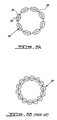
- the fuel nozzles 24 described herein can generate, in at least one embodiment thereof, a generally elliptically shaped fuel spray 90, i.e. having a generally elliptical transverse cross-sectional shape, as depicted in Fig. 6a .
- Each of the elliptically shaped fuel spray profiles 90 defines a major axis 94 and a minor axis 95, the major axis being longer than the minor axis.
- the fuel nozzles 24, and therefore their resulting elliptical spray shapes 90 are oriented such that the major axis 94 of the elliptical fuel spray 90 is substantially tangent to the annular axis 96 interlinking the fuel nozzles 24 about the combustor dome 26.
- Other orientations remain possible, much as fewer or more fuel nozzles may be used as required given the particular combustor.
- the fuel nozzles 24 include an outer spray tip 28 including a central fuel ejection nozzle 34 located at the center of the circular spray tip, the spray tip 28 being mounted to a nozzle body portion 30 through which at least one fuel flow passage 32 is defined.
- the spray tip 28 is substantially circular in shape (i.e. the perimeter of the transverse cross-section thereof is substantially circular).
- the entire spray tip portion 28 is integrally formed and mounted as a single piece to the nozzle body portion 30.
- the fuel flow passage 32 is in fluid flow communication with a fuel source (not shown) in order to provide a feed of fuel to the fuel nozzle 24, via the fuel manifold 22 (see Fig.
- the fuel manifold 22 is an internal manifold mounted within the gas generator casing in close proximity to the outer surface of the combustor dome 26, the nozzle body 30 is mounted directly to the internal fuel manifold 22.
- the fuel nozzle 24 may be a so-called “simplex" fuel nozzle as depicted in Fig. 3 , wherein only a single fuel flow passage 32 is provided and thus the fuel ejection nozzle 34 ejects a single initially conical spray of fuel.
- the fuel nozzle of the present invention may be of the "duplex" type.
- a flow restrictor 36 is disposed within the fuel flow passage 32 in order to control the volume of fuel flowing out through the fuel ejection nozzle 34.
- a generally conically shaped fuel spray 21 is initially produced, the conical fuel spray being concentric about a central fuel spray axis 38 extending from the central fuel ejection nozzle 34 into the combustion chamber 17.
- the spray tip 28 of the fuel nozzle 24 also provides air flow which mixes with the fuel spray ejected from the fuel ejection nozzle 34, which helps to achieve a desired final air/fuel mixture which is sprayed into the combustor for combustion.
- the spray tip 28 includes a number of airflow passages therein.
- These airflow passages include at least a first series of airflow passages 40 disposed in a radially outer region of the spray tip 28, i.e. radially outward from the central fuel ejection nozzle 34.
- the first series of airflow passages 40 includes two opposed groups of airflow passages, namely an outer group and an inner group, which are circumferentially spaced apart about the circular spray tip 28 and located on opposite sides of a transverse axis 42 that extends through the central fuel ejection nozzle 34 and thus both intersects and is substantially perpendicular to the fuel spray axis 38.
- the transverse axis 42 corresponds to the major axis 94 of the final elliptical spray 90 produced by the fuel nozzles 24, as described above relative to Fig.
- the fuel nozzles 24 may, in one possible embodiment, be arranged and orientated within the combustor 16 such that the transverse axes 42 of each of the fuel nozzles 24 is substantially tangent to the annular axis 96 (see Fig. 6a ) interconnecting the circumferentially spaced apart fuel nozzles 24 at the annular dome portion 26 of the combustor.
- the opposed groups of the first series of airflow passages 40 are symmetric with respect to the transverse axis 42.
- each of the groups of the first series of airflow passages 40 includes two rows of airflow passages, namely a radially inner set of passages 44 and a radially outer set of passages 46.
- these arcuate rows of passages 44,46 are parallel to each other but slightly circumferentially offset such that at least the exit apertures of the inner passages 44 are not circumferentially aligned with the radially outer passages 46. This enables a more evenly distributed flow of air produced by each of the opposed groups 40 of airflow passages.
- the first series of airflow passages 40 all define a substantially circular cross-sectional shape along at least a portion thereof, whether at the exit openings thereof or along their entire length.
- Each of the two opposed groups 40 of the first series of airflow passages are preferably inclined in the spray tip 28, such that they are respectively oriented towards each other and thus towards the intermediate transverse axis 42.
- the opposed groups 40 of the first series of airflow passages defined in the spray tip 28 of the fuel nozzles 24 thereby produce opposed fuel spray shaping air jets 23 which will intersect the initially conical fuel spray 21 ejected out of the central fuel ejection nozzle 34, thereby forming or shaping the fuel spray and thus generating a final fuel spray 90 which is differently shaped from the initial, conical, fuel spray.
- this shaped final fuel spray 90 is substantially elliptical, however other shapes of the final fuel spray are possible (i.e. the spray shaping air jets 23 form the fuel spray into a differently shaped final fuel spray).
- the air jets 23 act to flatten out the conical fuel spray 21 such as to generate the elliptically shaped final fuel spray 90 that exits from the fuel nozzle 24 into the combustion chamber.
- This elliptical fuel spray 90 defines a major axis 94 and a minor axis 95, the major axis 94 being at least parallel, and preferably coincident with, the transverse axis 42 of the fuel nozzle.
- this elliptically shaped final fuel spray produced by the fuel spray shaping air jets of the fuel nozzles 24 is but one possible configuration and/or shape which can be generated by directing the shaping air jets onto the initially conical fuel spray.
- the final fuel spray generated by the fuel nozzles 24 can be substantially flat, rectangular, oblong or any other possible different spray shape which the initial spray can be shaped or formed into and which may be suitable in a gas turbine engine combustor.
- the first series of airflow passages 40 which produce the opposed fuel spray shaping air jets may be angled within the spray tips such that, in additional to producing spray shaping air jets which will be directed at least partially towards to the central fuel ejection axis, may be angles at least partially tangentially about the spray tip such as to produce a swirling flow about this central fuel ejection axis of the fuel nozzle.
- the fuel spray shaping air jets can also impart, in one embodiment, swirling motion to the fuel spray being ejected.
- the spray tip 28 of the fuel nozzle 24 also includes, in at least one embodiment, a second series of airflow passages 50.
- the airflow passages of this second series 50 are located radially inwardly of the first series of airflow passages 40 on the spray tip, but still radially outward of the central fuel ejection nozzle 34.
- the second series 50 of airflow passages are disposed circumferentially about the central fuel ejection nozzle 34 in close proximity thereto.
- the airflow passages of this second series 50 are equally spaced apart and form an annular group of airflow passages which direct air directly into the initially conical fuel spray being ejected out of the fuel spray nozzle 34.
- the airflow provided by the second series 50 of airflow passages aids with the atomization of the fuel, however does not substantially change the shape of the fuel spray profile.
- the apertures of the second series of airflow passages 50 may also define a circular cross-sectional shape, and may be commonly angled or inclined within the spray tip such as to produce a ring of swirling air flowing out of the exit openings thereof.
- additional airflow passages may also be provided in the spray tip 28 of the fuel nozzle.
- the spray tip 28 includes another set of airflow passages 52 which are located about the outer periphery of the circular spray tip 28, circumferentially between the opposed groups of the first series of airflow passages 40.
- These arcuate groups of passages 52 at the periphery of the spray tip may be used to provide more airflow into the combustor, however the volume of air delivered through these additional airflow passages 52 is not sufficient to detract from, or cancel out the effect of, the spray shaping air jets produced by the opposed groups of the first series of airflow passages 40.
- the fuel nozzle 124 is similar to the fuel nozzle 24 described above, however the spray tip 128 of the fuel nozzle 124 is formed of two separate parts, namely a central portion 127, which includes the centrally located fuel ejection nozzle 134 and is mounted to the nozzle body 130, and a radially outer spray tip ring portion 129, which is mounted to the central portion 127 of the spray tip 128.
- the first series of airflow passages 40 are located in the spray tip ring portion 129
- the second series of airflow passages 50 are located in the central portion 127.
- the outer spray tip ring 129 is a separate part from the central portion 127 of the spray tip
- existing standard fuel nozzles having such a two part construction with a central portion can be retrofitted with the outer spray tip rings 129 in order to "convert" a regular, conical fuel spray nozzle into one of the present invention which will produce an elliptical fuel spray profile.
- the fuel nozzle 124 is also a "duplex" type fuel nozzle, and therefore has two separate concentric fuel feeds in the nozzle body portion 130 separately providing fuel to the fuel spray nozzle 134.
- a primary fuel flow is ejected by the fuel spray nozzle 134 via the central spray tip 133, while secondary fuel is ejected through a small annulus around the central tip 133.
- the first and second series of airflow passages 40 and 50, as well as the additional outer airflow passages 52, are also otherwise the same as those described above with respect to the fuel nozzle 24.
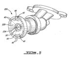
- the fuel nozzle 224 is a fuel nozzle assembly which has been retrofitted by adding a spray tip 228 air swirler in accordance with one alternate embodiment of the present invention to the existing central fuel ejection nozzle portion 234.
- the entire spray tip 228 is of a one-piece construction, and includes both the outer first series of airflow passages 40 which produce the fuel spray shaping jets, as well as the ring of inner airflow passages 50 which aid in the atomization of the fuel spray but do not otherwise substantially alter the overall shape of the fuel spray.
- Each of the opposed groups of the first series of airflow passages 40 which produce the fuel spray shape forming air jets therefrom, include an outer arcuate row of passages 46 and an inner arcuate row of passages 44.
- the radially outer arcuate row of airflow passage 46 is longer (i.e. comprises more apertures and thus more openings in the outer surface of the spray tip) than is the inner arcuate row of airflow passages 44. It is to be understood that all embodiments described above may include this configuration of the array of holes and passages of the first series of passages 40.
- the relative number of passages in each of the inner and outer rows 44, 46, as well as their relative diameters may be selected such as to achieve a desire overall size, and shape of the elliptical fuel spray profile produced by the fuel nozzle.
Landscapes
- Engineering & Computer Science (AREA)
- Chemical & Material Sciences (AREA)
- Combustion & Propulsion (AREA)
- Mechanical Engineering (AREA)
- General Engineering & Computer Science (AREA)
- Nozzles For Spraying Of Liquid Fuel (AREA)
Abstract
Description
- The invention relates generally to gas turbine engines and, more particularly, to fuel nozzles for such engines.
- Gas turbine engine combustors employ a plurality of fuel nozzles, typically arranged in an annular configuration, to spray the fuel into the combustion chamber of an annular combustor. Each of these fuel nozzles generates a spray of fuel which is generally conical in shape and which defines a generally circular cross-sectional profile, as shown in
Fig. 6b for example. However, in order to achieve a complete fuel spray coverage in annular combustors, a relatively large number of fuel nozzles are required about the combustor. Further, as the overall shape of the fuel spray produced is fixed, no alternatives exist for controlling the density and profile of fuel sprays in the combustor. - Accordingly, there is a need for an improved fuel nozzle for a gas turbine engine combustor which permits, inter alia, a reduction in the total number of parts of such combustors and thus lowers overall production costs.
- It is therefore an object of this invention to provide an improved fuel nozzle for a gas turbine engine.
- In one aspect, the present invention provides a fuel nozzle for use in a combustor of a gas turbine engine, the fuel nozzle comprising: a nozzle body defining at least one fuel flow passage therethrough; a spray tip mounted to the nozzle body, the spray tip having a central fuel ejection nozzle in flow communication with the at least one fuel flow passage and defining a fuel spray axis, the central fuel ejection nozzle ejecting fuel out of the spray tip in an initially conical fuel spray about the fuel spray axis; at least a first series of airflow passages disposed in said spray tip radially outwardly from the central fuel ejection nozzle, said first series of airflow passages including opposed groups of airflow passages, said opposed groups of airflow passages being circumferentially spaced apart and located on opposite sides of a transverse axis extending through said central fuel ejection nozzle perpendicularly to said fuel spray axis; and wherein said opposed groups of said first series of airflow passages are oriented towards said transverse axis such as to produce opposed fuel spray shaping air jets which intersect the initially conical fuel spray to generate a differently shaped final fuel spray.
- In another aspect, the present invention provides a gas turbine engine combustor assembly comprising: a combustor liner enclosing a combustion chamber, the combustor liner having an annular dome portion; a plurality of fuel nozzles disposed in the annular dome portion for injecting fuel into the combustion chamber, the fuel nozzles being equally circumferentially spaced apart about the annular dome portion to define an annular axis interconnecting the fuel nozzles, each of said fuel nozzles including: a spray tip having a central fuel ejection nozzle in flow communication with at least one fuel flow passage which receives fuel from a fuel source, the central fuel ejection nozzle defining a fuel spray axis and ejecting fuel into the combustion chamber in an initially conically shaped fuel spray about the fuel spray axis; a first series of airflow passages disposed in said spray tip radially outwardly from the central fuel ejection nozzle, said airflow passages including opposed groups of airflow passages, said opposed groups of airflow passages being circumferentially spaced apart in the spray tip and located on opposite sides of a transverse axis extending through said central fuel ejection nozzle perpendicularly to said fuel spray axis; said opposed groups of airflow passages being oriented towards said transverse axis such as to produce opposed fuel spray shaping air jets, said fuel spray shaping air jets intersecting said initially conical fuel spray such as to generate a final fuel spray having an elliptical cross-sectional shape defining a major axis parallel to said transverse axis and a minor axis perpendicular thereto.
- In yet another aspect, the present invention provides a fuel injection system of a gas turbine engine, the system comprising a fuel manifold, a plurality of nozzles mounted to said manifold and having spray tips for injecting an air/fuel mixture into a combustor of the gas turbine engine, at least one of said nozzles having a central fuel ejection nozzle and defining therein at least one fuel flow passage providing fluid flow communication between said fuel manifold and said central fuel ejection nozzle, a plurality of airflow passages disposed within said spray tip, the airflow passages including at least a first and second group of circumferentially spaced apart fuel-spray shaping airflow passages disposed on opposite sides of a transverse axis and oriented towards each other such as to produce opposed fuel spray shaping air jets, said fuel spray shaping air jets intersecting a fuel spray ejected out of said central fuel ejection nozzle to generate a shaped final fuel spray.
- Further details of these and other aspects of the present invention will be apparent from the detailed description and figures included below.
- Reference is now made to the accompanying figures depicting aspects of the present invention, in which:
-
Fig. 1 is a schematic cross-sectional side view of a gas turbine engine in which the present invention can be used; -
Fig. 2 is a three dimensional view of a portion of a combustor having a fuel nozzle in accordance with one aspect of the present invention; -
Fig. 3 is an isometric, partially sectioned, view of a fuel nozzle according to another aspect of the present invention; -
Fig. 4 is an isometric, partially sectioned, view of a fuel nozzle according to another aspect of the present invention; -
Fig. 5 is an isometric view of a fuel nozzle assembly according to another aspect of the present invention; -
Fig. 6a is a plan view of a schematic representation of spray coverage produced by the fuel nozzles of the present invention; -
Fig. 6b is a plan view of a schematic representation of spray coverage produced by fuel nozzles of the prior art; -
Fig. 7a is a schematic cross-sectional view of the fuel nozzle ofFig. 3 , showing the shaping of the fuel spray being ejected therefrom; -
Fig. 7b is a cross-section of the initially fuel spray, taken through line 7b-7b ofFig. 7a ; and -
Fig. 7c is a cross-sectional of the final shaped fuel spray, taken throughline 7c-7c ofFig. 7a . -
Figure 1 illustrates agas turbine engine 10 of a type preferably provided for use in subsonic flight, generally comprising in serial flow communication afan 12 through which ambient air is propelled, amultistage compressor 14 for pressurizing the air, acombustor 16 in which the compressed air is mixed with fuel and ignited for generating an annular stream of hot combustion gases, and aturbine section 18 for extracting energy from the combustion gases. - Fuel is injected into the
combustor 16 of thegas turbine engine 10 by afuel injection system 20, which includes a fuel source (not shown), at least one fuel conveying assembly orinternal fuel manifold 22 and a number offuel nozzles 24 engaged with the fuel manifold and which are operable to inject fuel into thecombustor 16 for mixing with the compressed air from thecompressor 14 and ignition of the resultant mixture. Thefan 12,compressor 14,combustor 16, andturbine 18 are preferably all concentric about a common central longitudinal axis 11 of thegas turbine engine 10. Thecombustor 16 is annular (and in at least one embodiment, an annular reverse flow combustor), and thus defines both an annularinternal combustion chamber 17 therewithin and an annular upstream ordome end wall 26 through which thefuel nozzles 24 protrude for injecting the air/fuel mixture into thecombustion chamber 17 of thecombustor 16. - Referring to
Fig. 2 , at least thespray tip 28 of afuel nozzle 24 is received within an opening 25 in theannular dome end 26 of the liner of thecombustor 16, for ejecting the air/fuel mixture into the combustor's combustion chamber. A plurality of thefuel nozzles 24 are provided about the full circumference of theannular dome 26, and in at least one embodiment are equally spaced therearound. Thus, the plurality offuel nozzles 24 define an annular axis 96 (seeFig. 6a ) which interlinks the fuel nozzles and extends circumferentially about the dome end of the combustor. While relative spacing of the circumferentially arrangedfuel nozzles 24 may be varied as required, thefuel nozzles 24 permit an overall combustor and fuel injection assembly which requires fewer fuel nozzles relative to most currently employed fuel injection systems for gas turbine engines. - As seen in
Fig. 6b , most fuel injection nozzles of the prior art generate a circularfinal fuel spray 92, i.e. having a profile that defines a generally circular transverse cross-sectional shape. Thus, in order to provide adequate coverage of sprayed fuel within the annular combustor, a relatively large number of standard fuel nozzles must be provided and located in a relatively closely spaced arrangement, such as that depicted inFig. 6b . Conversely, as described further below, thefuel nozzles 24 described herein can generate, in at least one embodiment thereof, a generally elliptically shapedfuel spray 90, i.e. having a generally elliptical transverse cross-sectional shape, as depicted inFig. 6a . As will be described, however, other shapes of the final fuel spray are possible with the fuel nozzles described herein, which can be desired in order to produce a variety of possible final fuel spray shapes, as desired and/or required. As can be seen inFig. 6a , when elliptically shapedfuel sprays 90 are produced,fewer fuel nozzles 24 producing such an ellipticallyshaped fuel spray 90 are needed (relative to those which produce a circular spray profile 92), in order to adequately cover the annular profile of a similarly sized combustor. Fewer fuel nozzles means lower production, assembly and operating costs, and also means lower overall weight, all of which are desirable improvements for gas turbine engines. Each of the elliptically shapedfuel spray profiles 90 defines amajor axis 94 and aminor axis 95, the major axis being longer than the minor axis. In at least one embodiment, thefuel nozzles 24, and therefore their resultingelliptical spray shapes 90, are oriented such that themajor axis 94 of theelliptical fuel spray 90 is substantially tangent to theannular axis 96 interlinking thefuel nozzles 24 about thecombustor dome 26. Other orientations remain possible, much as fewer or more fuel nozzles may be used as required given the particular combustor. AlthoughFig. 6a depicts all fuel sprays in the combustor being shaped, and therefore all fuel nozzles being of the type described therein, it is to be understood that only certain fuel nozzles within the combustor may be of the type described herein. This would result in different fuel nozzles in the combustor producing different fuel spray profiles. - Referring back to
Fig. 3 , thefuel nozzles 24 include anouter spray tip 28 including a centralfuel ejection nozzle 34 located at the center of the circular spray tip, thespray tip 28 being mounted to anozzle body portion 30 through which at least onefuel flow passage 32 is defined. In at least one embodiment, thespray tip 28 is substantially circular in shape (i.e. the perimeter of the transverse cross-section thereof is substantially circular). In thefuel nozzle 24 ofFig. 3 , the entirespray tip portion 28 is integrally formed and mounted as a single piece to thenozzle body portion 30. Thefuel flow passage 32 is in fluid flow communication with a fuel source (not shown) in order to provide a feed of fuel to thefuel nozzle 24, via the fuel manifold 22 (seeFig. 1 ) or other suitable fuel distribution members of thefuel injection system 20. In at least one embodiment, wherein thefuel manifold 22 is an internal manifold mounted within the gas generator casing in close proximity to the outer surface of thecombustor dome 26, thenozzle body 30 is mounted directly to theinternal fuel manifold 22. Thefuel nozzle 24 may be a so-called "simplex" fuel nozzle as depicted inFig. 3 , wherein only a singlefuel flow passage 32 is provided and thus thefuel ejection nozzle 34 ejects a single initially conical spray of fuel. Alternately, as will be described further below with reference toFig. 4 , the fuel nozzle of the present invention may be of the "duplex" type. Aflow restrictor 36 is disposed within thefuel flow passage 32 in order to control the volume of fuel flowing out through thefuel ejection nozzle 34. As noted above, and as best seen inFigs. 7a and 7b , upon initial ejection from thefuel ejection nozzle 34, a generally conically shapedfuel spray 21 is initially produced, the conical fuel spray being concentric about a centralfuel spray axis 38 extending from the centralfuel ejection nozzle 34 into thecombustion chamber 17. - The
spray tip 28 of thefuel nozzle 24 also provides air flow which mixes with the fuel spray ejected from thefuel ejection nozzle 34, which helps to achieve a desired final air/fuel mixture which is sprayed into the combustor for combustion. In order to provide the air flow, thespray tip 28 includes a number of airflow passages therein. - These airflow passages include at least a first series of
airflow passages 40 disposed in a radially outer region of thespray tip 28, i.e. radially outward from the centralfuel ejection nozzle 34. The first series ofairflow passages 40 includes two opposed groups of airflow passages, namely an outer group and an inner group, which are circumferentially spaced apart about thecircular spray tip 28 and located on opposite sides of atransverse axis 42 that extends through the centralfuel ejection nozzle 34 and thus both intersects and is substantially perpendicular to thefuel spray axis 38. Thetransverse axis 42 corresponds to themajor axis 94 of the finalelliptical spray 90 produced by thefuel nozzles 24, as described above relative toFig. 6a . Therefore, thefuel nozzles 24 may, in one possible embodiment, be arranged and orientated within thecombustor 16 such that thetransverse axes 42 of each of thefuel nozzles 24 is substantially tangent to the annular axis 96 (seeFig. 6a ) interconnecting the circumferentially spaced apartfuel nozzles 24 at theannular dome portion 26 of the combustor. In at least one embodiment, the opposed groups of the first series ofairflow passages 40 are symmetric with respect to thetransverse axis 42. - As shown in
Fig. 3 , in at least one possible embodiment, each of the groups of the first series ofairflow passages 40 includes two rows of airflow passages, namely a radially inner set ofpassages 44 and a radially outer set ofpassages 46. In one embodiment, these arcuate rows ofpassages inner passages 44 are not circumferentially aligned with the radiallyouter passages 46. This enables a more evenly distributed flow of air produced by each of theopposed groups 40 of airflow passages. In one possible embodiment, the first series ofairflow passages 40 all define a substantially circular cross-sectional shape along at least a portion thereof, whether at the exit openings thereof or along their entire length. Each of the twoopposed groups 40 of the first series of airflow passages are preferably inclined in thespray tip 28, such that they are respectively oriented towards each other and thus towards the intermediatetransverse axis 42. - As seen in
Figs. 7a-7c , theopposed groups 40 of the first series of airflow passages defined in thespray tip 28 of thefuel nozzles 24 thereby produce opposed fuel spray shapingair jets 23 which will intersect the initiallyconical fuel spray 21 ejected out of the centralfuel ejection nozzle 34, thereby forming or shaping the fuel spray and thus generating afinal fuel spray 90 which is differently shaped from the initial, conical, fuel spray. In the depicted embodiment, this shapedfinal fuel spray 90 is substantially elliptical, however other shapes of the final fuel spray are possible (i.e. the spray shapingair jets 23 form the fuel spray into a differently shaped final fuel spray). In the depicted embodiment, once the fuel spray shapingair jets 23 produced by the air flowing through theopposed groups 40 of the first series of airflow passages intersect the initiallyconical fuel spray 21 ejected from thenozzle 34, theair jets 23 act to flatten out theconical fuel spray 21 such as to generate the elliptically shapedfinal fuel spray 90 that exits from thefuel nozzle 24 into the combustion chamber. Thiselliptical fuel spray 90, as noted above with respect toFig. 6a , defines amajor axis 94 and aminor axis 95, themajor axis 94 being at least parallel, and preferably coincident with, thetransverse axis 42 of the fuel nozzle. - It is to be understood that this elliptically shaped final fuel spray produced by the fuel spray shaping air jets of the
fuel nozzles 24 is but one possible configuration and/or shape which can be generated by directing the shaping air jets onto the initially conical fuel spray. For example, the final fuel spray generated by thefuel nozzles 24 can be substantially flat, rectangular, oblong or any other possible different spray shape which the initial spray can be shaped or formed into and which may be suitable in a gas turbine engine combustor. The first series ofairflow passages 40 which produce the opposed fuel spray shaping air jets may be angled within the spray tips such that, in additional to producing spray shaping air jets which will be directed at least partially towards to the central fuel ejection axis, may be angles at least partially tangentially about the spray tip such as to produce a swirling flow about this central fuel ejection axis of the fuel nozzle. Thus, the fuel spray shaping air jets can also impart, in one embodiment, swirling motion to the fuel spray being ejected. - The
spray tip 28 of thefuel nozzle 24 also includes, in at least one embodiment, a second series ofairflow passages 50. The airflow passages of thissecond series 50 are located radially inwardly of the first series ofairflow passages 40 on the spray tip, but still radially outward of the centralfuel ejection nozzle 34. Thesecond series 50 of airflow passages are disposed circumferentially about the centralfuel ejection nozzle 34 in close proximity thereto. The airflow passages of thissecond series 50 are equally spaced apart and form an annular group of airflow passages which direct air directly into the initially conical fuel spray being ejected out of thefuel spray nozzle 34. The airflow provided by thesecond series 50 of airflow passages aids with the atomization of the fuel, however does not substantially change the shape of the fuel spray profile. The apertures of the second series ofairflow passages 50 may also define a circular cross-sectional shape, and may be commonly angled or inclined within the spray tip such as to produce a ring of swirling air flowing out of the exit openings thereof. - As seen in
Fig. 3 , additional airflow passages may also be provided in thespray tip 28 of the fuel nozzle. For example, thespray tip 28 includes another set ofairflow passages 52 which are located about the outer periphery of thecircular spray tip 28, circumferentially between the opposed groups of the first series ofairflow passages 40. These arcuate groups ofpassages 52 at the periphery of the spray tip may be used to provide more airflow into the combustor, however the volume of air delivered through theseadditional airflow passages 52 is not sufficient to detract from, or cancel out the effect of, the spray shaping air jets produced by the opposed groups of the first series ofairflow passages 40. - Referring now to
Fig. 4 , thefuel nozzle 124 is similar to thefuel nozzle 24 described above, however thespray tip 128 of thefuel nozzle 124 is formed of two separate parts, namely acentral portion 127, which includes the centrally locatedfuel ejection nozzle 134 and is mounted to thenozzle body 130, and a radially outer spraytip ring portion 129, which is mounted to thecentral portion 127 of thespray tip 128. In this embodiment, the first series ofairflow passages 40 are located in the spraytip ring portion 129, and the second series ofairflow passages 50 are located in thecentral portion 127. In this embodiment, as the outerspray tip ring 129 is a separate part from thecentral portion 127 of the spray tip, existing standard fuel nozzles having such a two part construction with a central portion can be retrofitted with the outer spray tip rings 129 in order to "convert" a regular, conical fuel spray nozzle into one of the present invention which will produce an elliptical fuel spray profile. Thefuel nozzle 124 is also a "duplex" type fuel nozzle, and therefore has two separate concentric fuel feeds in thenozzle body portion 130 separately providing fuel to thefuel spray nozzle 134. Thus, a primary fuel flow is ejected by thefuel spray nozzle 134 via thecentral spray tip 133, while secondary fuel is ejected through a small annulus around thecentral tip 133.Air openings 135, which are radially disposed between thecentral spray tip 133 and the second series ofairflow passages 50, provide air flow to the fuel spray much as per theair passages 50 in the embodiment ofFig. 3 . The first and second series ofairflow passages outer airflow passages 52, are also otherwise the same as those described above with respect to thefuel nozzle 24. - Referring to
Fig. 5 , thefuel nozzle 224 is a fuel nozzle assembly which has been retrofitted by adding aspray tip 228 air swirler in accordance with one alternate embodiment of the present invention to the existing central fuelejection nozzle portion 234. Thus, theentire spray tip 228 is of a one-piece construction, and includes both the outer first series ofairflow passages 40 which produce the fuel spray shaping jets, as well as the ring ofinner airflow passages 50 which aid in the atomization of the fuel spray but do not otherwise substantially alter the overall shape of the fuel spray. Each of the opposed groups of the first series ofairflow passages 40, which produce the fuel spray shape forming air jets therefrom, include an outer arcuate row ofpassages 46 and an inner arcuate row ofpassages 44. In the embodiment ofFig. 5 , the radially outer arcuate row ofairflow passage 46 is longer (i.e. comprises more apertures and thus more openings in the outer surface of the spray tip) than is the inner arcuate row ofairflow passages 44. It is to be understood that all embodiments described above may include this configuration of the array of holes and passages of the first series ofpassages 40. The relative number of passages in each of the inner andouter rows - Other modifications are of course possible, and the above description is meant to be exemplary only. One skilled in the art will recognize that changes may be made to the embodiments described without departing from the scope of the invention disclosed. For example, the number, size, layout and arrangement of the airflow apertures in the spray tip of the fuel nozzle may be varied, while nonetheless using opposed groups of airflow apertures to produce fuel spray shaping air jets that create an elliptically shaped final fuel spray profile. Still other modifications which fall within the scope of the present invention will be apparent to those skilled in the art, in light of a review of this disclosure, and such modifications are intended to fall within the appended claims.
Claims (15)
- A fuel nozzle (24; 124; 224) for use in a combustor of a gas turbine engine, the fuel nozzle defining at least one fuel flow passage (32) therethrough and comprising;
a spray tip (28; 128; 228) having a central fuel ejection nozzle (34; 134; 234) in flow communication with the at least one fuel flow passage and defining a fuel spray axis (38), the central fuel ejection nozzle ejecting fuel out of the spray tip in an initially conical fuel spray (21) about the fuel spray axis (38);
at least a first series of airflow passages (40) disposed in said spray tip (28; 128; 228) radially outwardly from the central fuel ejection nozzle (34; 134; 234), said first series of airflow passages (40) including opposed groups of airflow passages, said opposed groups of airflow passages being circumferentially spaced apart and located on opposite sides of a transverse axis (42) extending through said central fuel ejection nozzle (34; 134; 234) perpendicularly to said fuel spray axis; and
wherein said opposed groups of said first series of airflow passages (40) are oriented towards said transverse axis (42) such as to produce opposed fuel spray shaping air jets (23) which intersect the initially conical fuel spray (21) to generate a differently shaped final fuel spray. - The fuel nozzle as defined in claim 1, wherein the fuel spray shaping air jets (23) form a substantially elliptically shaped final fuel spray (90), having a major axis (94) parallel to said transverse axis (42) and a minor axis (95) perpendicular thereto.
- The fuel nozzle as defined in claim 1 or 2, wherein said opposed groups of airflow passages (40) are symmetric with respect to said transverse axis (42).
- The fuel nozzle as defined in claim 1, 2 or 3, wherein the spray tip (28; 128; 228) includes a second series of airflow passages (50) disposed in said spray tip circumferentially about the central fuel ejection nozzle (34; 134) and located radially inwards of the first series of airflow passages (40).
- The fuel nozzle as defined in claim 4, wherein said second series of airflow passages (50) include passage exit openings in said spray tip (28; 128; 228) that are evenly circumferentially spaced apart about the central fuel ejection nozzle (34; 134; 234), the second series of airflow passages (50) directing a substantially symmetric annular airflow to the initially conical fuel spray (21).
- The fuel nozzle as defined in claim 5, wherein each passage of said second series of airflow passages (50) defines a substantially circular cross-sectional area.
- The fuel nozzle as defined in claim 5 or 6, wherein passages of said second series of airflow passages (50) are inclined such as to produce a swirling airflow therefrom.
- The fuel nozzle as defined in any preceding claim, wherein at least a portion of said passages of said first series of airflow passages (40) define a substantially circular cross-sectional area.
- The fuel nozzle as defined in claim 8, wherein said passages of said first series of airflow passages (40) have exit openings having substantially circular cross-sectional areas.
- The fuel nozzle as defined in any preceding claim, wherein the spray tip (128) includes a central portion (134) mounted to a nozzle body (130) and a separate air swirler portion (129) mounted to the central portion, the first series of airflow passages (40) being disposed in said separate air swirler portion (129).
- The fuel nozzle as defined in any preceding claim, wherein the spray tip (28; 128; 228) is substantially circular.
- A gas turbine engine combustor assembly comprising:a combustor liner enclosing a combustion chamber, the combustor liner having an annular dome portion (26);
a plurality of fuel nozzles (24) as claimed in any preceding claim disposed in the annular dome portion (26) for injecting fuel into the combustion chamber, the fuel nozzles being equally circumferentially spaced apart about the annular dome portion (26) to define an annular axis (96) interconnecting the fuel nozzles (24). - The combustor as defined in claim 12, wherein the transverse axis (42) is substantially tangential to said annular axis (96) interconnecting the fuel nozzles (24) about the dome portion (26) of the combustor.
- A fuel injection system of a gas turbine engine, the system comprising a fuel manifold, a plurality of nozzles (24; 124; 224) mounted to said manifold and having spray tips (28; 128; 228) for injecting an air/fuel mixture into a combustor of the gas turbine engine, at least one of said nozzles (24; 124; 224) having a central fuel ejection nozzle (34;134; 234) and defining therein at least one fuel flow passage providing fluid flow communication between said fuel manifold and said central fuel ejection nozzle, a plurality of airflow passages (40, 50) disposed within said spray tip, the airflow passages including at least a first and second group (40, 50) of circumferentially spaced apart fuel-spray shaping airflow passages disposed on opposite sides of a transverse axis (42) and oriented towards each other such as to produce opposed fuel spray shaping air jets (23), said fuel spray shaping air jets (23) intersecting a fuel spray (21) ejected out of said central fuel ejection nozzle to generate a shaped final fuel spray (90).
- The fuel injection system as defined in claim 14 wherein said at least one of said fuel nozzles (24) as claimed in any of claims 1 to 11.
Applications Claiming Priority (1)
| Application Number | Priority Date | Filing Date | Title |
|---|---|---|---|
| US11/763,119 US8146365B2 (en) | 2007-06-14 | 2007-06-14 | Fuel nozzle providing shaped fuel spray |
Publications (3)
| Publication Number | Publication Date |
|---|---|
| EP2003398A2 true EP2003398A2 (en) | 2008-12-17 |
| EP2003398A3 EP2003398A3 (en) | 2012-10-03 |
| EP2003398B1 EP2003398B1 (en) | 2018-10-17 |
Family
ID=39758436
Family Applications (1)
| Application Number | Title | Priority Date | Filing Date |
|---|---|---|---|
| EP08252061.0A Ceased EP2003398B1 (en) | 2007-06-14 | 2008-06-16 | Fuel nozzle providing shaped fuel spray |
Country Status (4)
| Country | Link |
|---|---|
| US (1) | US8146365B2 (en) |
| EP (1) | EP2003398B1 (en) |
| CA (1) | CA2690431C (en) |
| WO (1) | WO2008151441A1 (en) |
Cited By (5)
| Publication number | Priority date | Publication date | Assignee | Title |
|---|---|---|---|---|
| DE102008026459A1 (en) * | 2008-06-03 | 2009-12-10 | E.On Ruhrgas Ag | Burner for combustion device in gas turbine system, has plate shaped element arranged in fuel injector, and including fuel passage openings that are arranged in rings and displaced to each other in radial direction |
| WO2014130161A3 (en) * | 2013-01-02 | 2014-12-04 | Parker-Hannifin Corporation | Direct injection multipoint nozzle |
| CN104956150A (en) * | 2012-12-11 | 2015-09-30 | 西门子公司 | Air directed fuel injection |
| EP2940389A1 (en) * | 2014-05-02 | 2015-11-04 | Siemens Aktiengesellschaft | Combustor burner arrangement |
| US11313560B2 (en) | 2018-07-18 | 2022-04-26 | General Electric Company | Combustor assembly for a heat engine |
Families Citing this family (24)
| Publication number | Priority date | Publication date | Assignee | Title |
|---|---|---|---|---|
| US8479519B2 (en) * | 2009-01-07 | 2013-07-09 | General Electric Company | Method and apparatus to facilitate cooling of a diffusion tip within a gas turbine engine |
| US20110072823A1 (en) * | 2009-09-30 | 2011-03-31 | Daih-Yeou Chen | Gas turbine engine fuel injector |
| EP2439447A1 (en) * | 2010-10-05 | 2012-04-11 | Siemens Aktiengesellschaft | Fuel nozzle, gas turbine combustion chamber and burner with such a fuel nozzle |
| US10317081B2 (en) | 2011-01-26 | 2019-06-11 | United Technologies Corporation | Fuel injector assembly |
| WO2014081334A1 (en) * | 2012-11-21 | 2014-05-30 | General Electric Company | Anti-coking liquid fuel cartridge |
| WO2015017002A2 (en) | 2013-07-15 | 2015-02-05 | United Technologies Corporation | Swirler mount interface for gas turbine engine combustor |
| WO2015053818A2 (en) | 2013-07-15 | 2015-04-16 | United Technologies Corporation | Swirler mount interface for gas turbine engine combustor |
| EP3022492A4 (en) * | 2013-07-15 | 2017-02-22 | Hamilton Sundstrand Corporation | Combustion system, apparatus and method |
| WO2015030928A1 (en) | 2013-08-30 | 2015-03-05 | United Technologies Corporation | Swirler mount interface for a gas turbine engine combustor |
| US9995220B2 (en) | 2013-12-20 | 2018-06-12 | Pratt & Whitney Canada Corp. | Fluid manifold for gas turbine engine and method for delivering fuel to a combustor using same |
| US9920674B2 (en) | 2014-01-09 | 2018-03-20 | Cummins Inc. | Variable spray angle injector arrangement |
| EP3102887B1 (en) | 2014-01-24 | 2023-11-15 | RTX Corporation | Axial staged combustor with restricted main fuel injector |
| RU2662773C2 (en) * | 2014-04-04 | 2018-07-31 | Дженерал Электрик Компани | Preliminary film formation cartridge for the liquid fuel |
| CN106574775B (en) * | 2014-08-14 | 2019-10-18 | 西门子公司 | Multifunctional fuel nozzle with dual orifice atomizer |
| WO2016024975A1 (en) * | 2014-08-14 | 2016-02-18 | Siemens Aktiengesellschaft | Multi-functional fuel nozzle with a heat shield |
| US9863638B2 (en) * | 2015-04-01 | 2018-01-09 | Delavan Inc. | Air shrouds with improved air wiping |
| US11149952B2 (en) | 2016-12-07 | 2021-10-19 | Raytheon Technologies Corporation | Main mixer in an axial staged combustor for a gas turbine engine |
| US10801728B2 (en) | 2016-12-07 | 2020-10-13 | Raytheon Technologies Corporation | Gas turbine engine combustor main mixer with vane supported centerbody |
| USD849226S1 (en) * | 2017-05-24 | 2019-05-21 | Hamworthy Combustion Engineering Limited | Atomizer |
| US11371706B2 (en) * | 2017-12-18 | 2022-06-28 | General Electric Company | Premixed pilot nozzle for gas turbine combustor |
| CN109915855A (en) * | 2019-03-01 | 2019-06-21 | 西北工业大学 | Double oil circuits liquidate simple nozzle |
| US12007116B2 (en) * | 2021-02-19 | 2024-06-11 | Pratt & Whitney Canada Corp. | Dual pressure fuel nozzles |
| DE102021110616A1 (en) * | 2021-04-26 | 2022-10-27 | Rolls-Royce Deutschland Ltd & Co Kg | Fuel nozzle with different first and second outflow openings for providing a hydrogen-air mixture |
| US20220412264A1 (en) * | 2021-06-24 | 2022-12-29 | Delavan Inc. | Radial equilibrated combustion nozzle array |
Citations (4)
| Publication number | Priority date | Publication date | Assignee | Title |
|---|---|---|---|---|
| US3886736A (en) * | 1972-11-09 | 1975-06-03 | Westinghouse Electric Corp | Combustion apparatus for gas turbine |
| WO1999061838A1 (en) * | 1998-05-22 | 1999-12-02 | Pratt & Whitney Canada Corp. | Gas turbine fuel injector |
| WO2005040679A2 (en) * | 2003-10-23 | 2005-05-06 | Otv Sa | System for injecting pasty, semipasty or liquid waste into an incineration furnace |
| EP1707873A1 (en) * | 2005-03-17 | 2006-10-04 | Pratt & Whitney Canada Corp. | Modular fuel nozzle and method of making |
Family Cites Families (63)
| Publication number | Priority date | Publication date | Assignee | Title |
|---|---|---|---|---|
| US2151540A (en) | 1935-06-19 | 1939-03-21 | Varga Alexander | Heat exchanger and method of making same |
| US2946185A (en) | 1953-10-29 | 1960-07-26 | Thompson Ramo Wooldridge Inc | Fuel-air manifold for an afterburner |
| FR1292404A (en) | 1961-03-24 | 1962-05-04 | Nord Aviation | Multiple injection grid for ramjet or turbojet afterburning device |
| US3472025A (en) | 1967-08-28 | 1969-10-14 | Parker Hannifin Corp | Nozzle and manifold assembly |
| US3521824A (en) | 1968-10-11 | 1970-07-28 | Delavan Manufacturing Co | Air-liquid flat spray nozzle |
| US3859787A (en) | 1974-02-04 | 1975-01-14 | Gen Motors Corp | Combustion apparatus |
| US4100733A (en) | 1976-10-04 | 1978-07-18 | United Technologies Corporation | Premix combustor |
| US4327547A (en) | 1978-11-23 | 1982-05-04 | Rolls-Royce Limited | Fuel injectors |
| US4218020A (en) | 1979-02-23 | 1980-08-19 | General Motors Corporation | Elliptical airblast nozzle |
| US4322945A (en) | 1980-04-02 | 1982-04-06 | United Technologies Corporation | Fuel nozzle guide heat shield for a gas turbine engine |
| US4483137A (en) | 1981-07-30 | 1984-11-20 | Solar Turbines, Incorporated | Gas turbine engine construction and operation |
| US4404806A (en) | 1981-09-04 | 1983-09-20 | General Motors Corporation | Gas turbine prechamber and fuel manifold structure |
| FR2572463B1 (en) * | 1984-10-30 | 1989-01-20 | Snecma | INJECTION SYSTEM WITH VARIABLE GEOMETRY. |
| FR2588919B1 (en) | 1985-10-18 | 1987-12-04 | Snecma | SECTORIZED BOWL INJECTION DEVICE |
| US5036657A (en) | 1987-06-25 | 1991-08-06 | General Electric Company | Dual manifold fuel system |
| US4902409A (en) | 1988-01-19 | 1990-02-20 | Sprout-Bauer, Inc. | Nozzle for screen apparatus |
| US4941617A (en) | 1988-12-14 | 1990-07-17 | United Technologies Corporation | Airblast fuel nozzle |
| GB9018013D0 (en) | 1990-08-16 | 1990-10-03 | Rolls Royce Plc | Gas turbine engine combustor |
| GB9018014D0 (en) | 1990-08-16 | 1990-10-03 | Rolls Royce Plc | Gas turbine engine combustor |
| GB2247522B (en) | 1990-09-01 | 1993-11-10 | Rolls Royce Plc | Gas turbine engine combustor |
| US5231833A (en) | 1991-01-18 | 1993-08-03 | General Electric Company | Gas turbine engine fuel manifold |
| US5211005A (en) * | 1992-04-16 | 1993-05-18 | Avco Corporation | High density fuel injection manifold |
| US5417054A (en) | 1992-05-19 | 1995-05-23 | Fuel Systems Textron, Inc. | Fuel purging fuel injector |
| US5423178A (en) | 1992-09-28 | 1995-06-13 | Parker-Hannifin Corporation | Multiple passage cooling circuit method and device for gas turbine engine fuel nozzle |
| FR2698157B1 (en) | 1992-11-18 | 1994-12-16 | Snecma | Aerodynamic combustion chamber injection system. |
| US5331805A (en) * | 1993-04-22 | 1994-07-26 | Alliedsignal Inc. | Reduced diameter annular combustor |
| WO1994028351A1 (en) | 1993-06-01 | 1994-12-08 | Pratt & Whitney Canada, Inc. | Radially mounted air blast fuel injector |
| US5423173A (en) | 1993-07-29 | 1995-06-13 | United Technologies Corporation | Fuel injector and method of operating the fuel injector |
| US5400968A (en) | 1993-08-16 | 1995-03-28 | Solar Turbines Incorporated | Injector tip cooling using fuel as the coolant |
| GB9326367D0 (en) | 1993-12-23 | 1994-02-23 | Rolls Royce Plc | Fuel injection apparatus |
| DE69506308T2 (en) | 1994-04-20 | 1999-08-26 | Rolls-Royce Plc | Fuel injector for gas turbine engines |
| US5419115A (en) | 1994-04-29 | 1995-05-30 | United Technologies Corporation | Bulkhead and fuel nozzle guide assembly for an annular combustion chamber |
| DE4427222A1 (en) | 1994-08-01 | 1996-02-08 | Bmw Rolls Royce Gmbh | Heat shield for a gas turbine combustor |
| US5598696A (en) | 1994-09-20 | 1997-02-04 | Parker-Hannifin Corporation | Clip attached heat shield |
| GB2298916B (en) | 1995-03-15 | 1998-11-04 | Rolls Royce Plc | Annular combustor |
| US5622489A (en) | 1995-04-13 | 1997-04-22 | Monro; Richard J. | Fuel atomizer and apparatus and method for reducing NOx |
| DE19515537A1 (en) | 1995-04-27 | 1996-10-31 | Bmw Rolls Royce Gmbh | Head part of a gas turbine annular combustion chamber |
| US5679135A (en) | 1996-02-08 | 1997-10-21 | The United States Of America As Represented By The United States Department Of Energy | Process for off-gas particulate removal and apparatus therefor |
| FR2751731B1 (en) * | 1996-07-25 | 1998-09-04 | Snecma | BOWL DEFLECTOR ASSEMBLY FOR A TURBOMACHINE COMBUSTION CHAMBER |
| US5848525A (en) | 1996-08-30 | 1998-12-15 | General Electric Company | Fuel manifold staging valve |
| US5771696A (en) | 1996-10-21 | 1998-06-30 | General Electric Company | Internal manifold fuel injection assembly for gas turbine |
| US5983642A (en) | 1997-10-13 | 1999-11-16 | Siemens Westinghouse Power Corporation | Combustor with two stage primary fuel tube with concentric members and flow regulating |
| US6141968A (en) | 1997-10-29 | 2000-11-07 | Pratt & Whitney Canada Corp. | Fuel nozzle for gas turbine engine with slotted fuel conduits and cover |
| CA2225263A1 (en) | 1997-12-19 | 1999-06-19 | Rolls-Royce Plc | Fluid manifold |
| JPH11257664A (en) | 1997-12-30 | 1999-09-21 | United Technol Corp <Utc> | Fuel injection nozzle/guide assembly for gas turbine engine |
| US6109038A (en) | 1998-01-21 | 2000-08-29 | Siemens Westinghouse Power Corporation | Combustor with two stage primary fuel assembly |
| DE59902355D1 (en) | 1998-06-04 | 2002-09-19 | Siemens Ag | fuel nozzle |
| US6289676B1 (en) | 1998-06-26 | 2001-09-18 | Pratt & Whitney Canada Corp. | Simplex and duplex injector having primary and secondary annular lud channels and primary and secondary lud nozzles |
| US6119459A (en) | 1998-08-18 | 2000-09-19 | Alliedsignal Inc. | Elliptical axial combustor swirler |
| US6024301A (en) | 1998-10-16 | 2000-02-15 | Combustion Components Associates, Inc. | Low NOx liquid fuel oil atomizer spray plate and fabrication method thereof |
| US6149075A (en) | 1999-09-07 | 2000-11-21 | General Electric Company | Methods and apparatus for shielding heat from a fuel nozzle stem of fuel nozzle |
| US6761035B1 (en) | 1999-10-15 | 2004-07-13 | General Electric Company | Thermally free fuel nozzle |
| US6256995B1 (en) | 1999-11-29 | 2001-07-10 | Pratt & Whitney Canada Corp. | Simple low cost fuel nozzle support |
| US6463739B1 (en) | 2001-02-05 | 2002-10-15 | General Electric Company | Afterburner heat shield |
| DE60217768T2 (en) | 2001-07-18 | 2007-11-15 | Rolls-Royce Plc | Fuel delivery device |
| US6625971B2 (en) | 2001-09-14 | 2003-09-30 | United Technologies Corporation | Fuel nozzle producing skewed spray pattern |
| US7028484B2 (en) | 2002-08-30 | 2006-04-18 | Pratt & Whitney Canada Corp. | Nested channel ducts for nozzle construction and the like |
| US6871488B2 (en) | 2002-12-17 | 2005-03-29 | Pratt & Whitney Canada Corp. | Natural gas fuel nozzle for gas turbine engine |
| JP4065947B2 (en) | 2003-08-05 | 2008-03-26 | 独立行政法人 宇宙航空研究開発機構 | Fuel / air premixer for gas turbine combustor |
| US7117678B2 (en) | 2004-04-02 | 2006-10-10 | Pratt & Whitney Canada Corp. | Fuel injector head |
| KR100742202B1 (en) | 2005-10-13 | 2007-07-24 | 진명이십일 (주) | The injection nozzle structure of injector |
| FR2899314B1 (en) * | 2006-03-30 | 2008-05-09 | Snecma Sa | DEVICE FOR INJECTING A MIXTURE OF AIR AND FUEL, COMBUSTION CHAMBER AND TURBOMACHINE HAVING SUCH A DEVICE |
| FR2901349B1 (en) * | 2006-05-19 | 2008-09-05 | Snecma Sa | COMBUSTION CHAMBER OF A TURBOMACHINE |
-
2007
- 2007-06-14 US US11/763,119 patent/US8146365B2/en active Active
-
2008
- 2008-06-12 WO PCT/CA2008/001141 patent/WO2008151441A1/en active Application Filing
- 2008-06-12 CA CA2690431A patent/CA2690431C/en not_active Expired - Fee Related
- 2008-06-16 EP EP08252061.0A patent/EP2003398B1/en not_active Ceased
Patent Citations (4)
| Publication number | Priority date | Publication date | Assignee | Title |
|---|---|---|---|---|
| US3886736A (en) * | 1972-11-09 | 1975-06-03 | Westinghouse Electric Corp | Combustion apparatus for gas turbine |
| WO1999061838A1 (en) * | 1998-05-22 | 1999-12-02 | Pratt & Whitney Canada Corp. | Gas turbine fuel injector |
| WO2005040679A2 (en) * | 2003-10-23 | 2005-05-06 | Otv Sa | System for injecting pasty, semipasty or liquid waste into an incineration furnace |
| EP1707873A1 (en) * | 2005-03-17 | 2006-10-04 | Pratt & Whitney Canada Corp. | Modular fuel nozzle and method of making |
Cited By (18)
| Publication number | Priority date | Publication date | Assignee | Title |
|---|---|---|---|---|
| DE102008026459A1 (en) * | 2008-06-03 | 2009-12-10 | E.On Ruhrgas Ag | Burner for combustion device in gas turbine system, has plate shaped element arranged in fuel injector, and including fuel passage openings that are arranged in rings and displaced to each other in radial direction |
| CN104956150A (en) * | 2012-12-11 | 2015-09-30 | 西门子公司 | Air directed fuel injection |
| CN104956150B (en) * | 2012-12-11 | 2018-01-12 | 西门子公司 | The fuel injection that air is oriented to |
| US9835335B2 (en) | 2012-12-11 | 2017-12-05 | Siemens Aktiengesellschaft | Air directed fuel injection |
| GB2524914B (en) * | 2013-01-02 | 2017-08-23 | Parker Hannifin Corp | Direct injection multipoint nozzle |
| WO2014130161A3 (en) * | 2013-01-02 | 2014-12-04 | Parker-Hannifin Corporation | Direct injection multipoint nozzle |
| GB2524914A (en) * | 2013-01-02 | 2015-10-07 | Parker Hannifin Corp | Direct injection multipoint nozzle |
| US9810186B2 (en) | 2013-01-02 | 2017-11-07 | Parker-Hannifin Corporation | Direct injection multipoint nozzle |
| EP2940389A1 (en) * | 2014-05-02 | 2015-11-04 | Siemens Aktiengesellschaft | Combustor burner arrangement |
| CN106461219A (en) * | 2014-05-02 | 2017-02-22 | 西门子股份公司 | Combustor burner arrangement |
| US20170045231A1 (en) * | 2014-05-02 | 2017-02-16 | Siemens Aktiengesellschaft | Combustor burner arrangement |
| CN106415132A (en) * | 2014-05-02 | 2017-02-15 | 西门子股份公司 | Combustor burner arrangement |
| WO2015166017A1 (en) * | 2014-05-02 | 2015-11-05 | Siemens Aktiengesellschaft | Combustor burner arrangement |
| RU2642971C1 (en) * | 2014-05-02 | 2018-01-29 | Сименс Акциенгезелльшафт | Location of combustion chamber burners |
| RU2672216C2 (en) * | 2014-05-02 | 2018-11-12 | Сименс Акциенгезелльшафт | Combustor burner arrangement |
| US10533748B2 (en) * | 2014-05-02 | 2020-01-14 | Siemens Aktiengesellschaft | Combustor burner arrangement |
| CN106461219B (en) * | 2014-05-02 | 2020-07-31 | 西门子股份公司 | Burner arrangement for a combustion device |
| US11313560B2 (en) | 2018-07-18 | 2022-04-26 | General Electric Company | Combustor assembly for a heat engine |
Also Published As
| Publication number | Publication date |
|---|---|
| WO2008151441A1 (en) | 2008-12-18 |
| US8146365B2 (en) | 2012-04-03 |
| EP2003398B1 (en) | 2018-10-17 |
| US20080307791A1 (en) | 2008-12-18 |
| CA2690431C (en) | 2015-11-24 |
| CA2690431A1 (en) | 2008-12-18 |
| EP2003398A3 (en) | 2012-10-03 |
Similar Documents
| Publication | Publication Date | Title |
|---|---|---|
| EP2003398B1 (en) | Fuel nozzle providing shaped fuel spray | |
| US11226101B2 (en) | Combustor swirler | |
| AU2003243993B2 (en) | Discrete jet atomizer | |
| EP2589877B1 (en) | Annular combustor with multipoint fuel injection arrangements | |
| US7003958B2 (en) | Multi-sided diffuser for a venturi in a fuel injector for a gas turbine | |
| EP1080327B1 (en) | Gas turbine fuel injector | |
| US10208956B2 (en) | Combustor for gas turbine engine | |
| EP0700499B1 (en) | A gas turbine engine combustion chamber | |
| US7036316B2 (en) | Methods and apparatus for cooling turbine engine combustor exit temperatures | |
| EP0550218B1 (en) | Gas turbine combustors | |
| US5713205A (en) | Air atomized discrete jet liquid fuel injector and method | |
| US5351475A (en) | Aerodynamic fuel injection system for a gas turbine combustion chamber | |
| CN100557318C (en) | A kind of integral fuel jet axial swirler pre-mixing preevaporated low pollution combustion chamber | |
| US6571559B1 (en) | Anti-carboning fuel-air mixer for a gas turbine engine combustor | |
| CN108351105A (en) | Pre- membrane type fuel/air mixer | |
| US5195315A (en) | Double dome combustor with counter rotating toroidal vortices and dual radial fuel injection | |
| CN109073224B (en) | Intake swirler for a turbomachine injection system comprising an aerodynamic deflector at the inlet | |
| EP4187154A1 (en) | Fuel nozzle with restricted core air passage | |
| US11754287B2 (en) | Fuel injector assembly for a turbine engine | |
| US11448175B1 (en) | Fuel nozzle |
Legal Events
| Date | Code | Title | Description |
|---|---|---|---|
| PUAI | Public reference made under article 153(3) epc to a published international application that has entered the european phase |
Free format text: ORIGINAL CODE: 0009012 |
|
| AK | Designated contracting states |
Kind code of ref document: A2 Designated state(s): AT BE BG CH CY CZ DE DK EE ES FI FR GB GR HR HU IE IS IT LI LT LU LV MC MT NL NO PL PT RO SE SI SK TR |
|
| AX | Request for extension of the european patent |
Extension state: AL BA MK RS |
|
| PUAL | Search report despatched |
Free format text: ORIGINAL CODE: 0009013 |
|
| AK | Designated contracting states |
Kind code of ref document: A3 Designated state(s): AT BE BG CH CY CZ DE DK EE ES FI FR GB GR HR HU IE IS IT LI LT LU LV MC MT NL NO PL PT RO SE SI SK TR |
|
| AX | Request for extension of the european patent |
Extension state: AL BA MK RS |
|
| RIC1 | Information provided on ipc code assigned before grant |
Ipc: F23D 11/10 20060101ALI20120824BHEP Ipc: F23R 3/28 20060101ALI20120824BHEP Ipc: F23R 3/10 20060101AFI20120824BHEP Ipc: F23D 11/24 20060101ALI20120824BHEP Ipc: F23D 11/12 20060101ALI20120824BHEP |
|
| 17P | Request for examination filed |
Effective date: 20130403 |
|
| AKX | Designation fees paid |
Designated state(s): DE FR GB |
|
| STAA | Information on the status of an ep patent application or granted ep patent |
Free format text: STATUS: EXAMINATION IS IN PROGRESS |
|
| 17Q | First examination report despatched |
Effective date: 20170704 |
|
| GRAP | Despatch of communication of intention to grant a patent |
Free format text: ORIGINAL CODE: EPIDOSNIGR1 |
|
| STAA | Information on the status of an ep patent application or granted ep patent |
Free format text: STATUS: GRANT OF PATENT IS INTENDED |
|
| INTG | Intention to grant announced |
Effective date: 20180405 |
|
| GRAS | Grant fee paid |
Free format text: ORIGINAL CODE: EPIDOSNIGR3 |
|
| GRAJ | Information related to disapproval of communication of intention to grant by the applicant or resumption of examination proceedings by the epo deleted |
Free format text: ORIGINAL CODE: EPIDOSDIGR1 |
|
| GRAL | Information related to payment of fee for publishing/printing deleted |
Free format text: ORIGINAL CODE: EPIDOSDIGR3 |
|
| STAA | Information on the status of an ep patent application or granted ep patent |
Free format text: STATUS: EXAMINATION IS IN PROGRESS |
|
| GRAR | Information related to intention to grant a patent recorded |
Free format text: ORIGINAL CODE: EPIDOSNIGR71 |
|
| STAA | Information on the status of an ep patent application or granted ep patent |
Free format text: STATUS: GRANT OF PATENT IS INTENDED |
|
| GRAA | (expected) grant |
Free format text: ORIGINAL CODE: 0009210 |
|
| STAA | Information on the status of an ep patent application or granted ep patent |
Free format text: STATUS: THE PATENT HAS BEEN GRANTED |
|
| INTC | Intention to grant announced (deleted) | ||
| AK | Designated contracting states |
Kind code of ref document: B1 Designated state(s): DE FR GB |
|
| INTG | Intention to grant announced |
Effective date: 20180911 |
|
| REG | Reference to a national code |
Ref country code: GB Ref legal event code: FG4D |
|
| REG | Reference to a national code |
Ref country code: DE Ref legal event code: R096 Ref document number: 602008057426 Country of ref document: DE |
|
| REG | Reference to a national code |
Ref country code: DE Ref legal event code: R097 Ref document number: 602008057426 Country of ref document: DE |
|
| PGFP | Annual fee paid to national office [announced via postgrant information from national office to epo] |
Ref country code: DE Payment date: 20190521 Year of fee payment: 12 |
|
| PLBE | No opposition filed within time limit |
Free format text: ORIGINAL CODE: 0009261 |
|
| STAA | Information on the status of an ep patent application or granted ep patent |
Free format text: STATUS: NO OPPOSITION FILED WITHIN TIME LIMIT |
|
| PGFP | Annual fee paid to national office [announced via postgrant information from national office to epo] |
Ref country code: FR Payment date: 20190522 Year of fee payment: 12 |
|
| 26N | No opposition filed |
Effective date: 20190718 |
|
| PGFP | Annual fee paid to national office [announced via postgrant information from national office to epo] |
Ref country code: GB Payment date: 20190522 Year of fee payment: 12 |
|
| REG | Reference to a national code |
Ref country code: DE Ref legal event code: R119 Ref document number: 602008057426 Country of ref document: DE |
|
| GBPC | Gb: european patent ceased through non-payment of renewal fee |
Effective date: 20200616 |
|
| PG25 | Lapsed in a contracting state [announced via postgrant information from national office to epo] |
Ref country code: FR Free format text: LAPSE BECAUSE OF NON-PAYMENT OF DUE FEES Effective date: 20200630 Ref country code: GB Free format text: LAPSE BECAUSE OF NON-PAYMENT OF DUE FEES Effective date: 20200616 |
|
| PG25 | Lapsed in a contracting state [announced via postgrant information from national office to epo] |
Ref country code: DE Free format text: LAPSE BECAUSE OF NON-PAYMENT OF DUE FEES Effective date: 20210101 |