EP2003310A2 - Variable geometry nacelle for an aircraft engine - Google Patents
Variable geometry nacelle for an aircraft engine Download PDFInfo
- Publication number
- EP2003310A2 EP2003310A2 EP08252058A EP08252058A EP2003310A2 EP 2003310 A2 EP2003310 A2 EP 2003310A2 EP 08252058 A EP08252058 A EP 08252058A EP 08252058 A EP08252058 A EP 08252058A EP 2003310 A2 EP2003310 A2 EP 2003310A2
- Authority
- EP
- European Patent Office
- Prior art keywords
- leading edge
- slats
- nacelle
- recited
- assembly
- Prior art date
- Legal status (The legal status is an assumption and is not a legal conclusion. Google has not performed a legal analysis and makes no representation as to the accuracy of the status listed.)
- Withdrawn
Links
Images


Classifications
-
- F—MECHANICAL ENGINEERING; LIGHTING; HEATING; WEAPONS; BLASTING
- F02—COMBUSTION ENGINES; HOT-GAS OR COMBUSTION-PRODUCT ENGINE PLANTS
- F02C—GAS-TURBINE PLANTS; AIR INTAKES FOR JET-PROPULSION PLANTS; CONTROLLING FUEL SUPPLY IN AIR-BREATHING JET-PROPULSION PLANTS
- F02C7/00—Features, components parts, details or accessories, not provided for in, or of interest apart form groups F02C1/00 - F02C6/00; Air intakes for jet-propulsion plants
- F02C7/04—Air intakes for gas-turbine plants or jet-propulsion plants
- F02C7/042—Air intakes for gas-turbine plants or jet-propulsion plants having variable geometry
-
- B—PERFORMING OPERATIONS; TRANSPORTING
- B64—AIRCRAFT; AVIATION; COSMONAUTICS
- B64D—EQUIPMENT FOR FITTING IN OR TO AIRCRAFT; FLIGHT SUITS; PARACHUTES; ARRANGEMENT OR MOUNTING OF POWER PLANTS OR PROPULSION TRANSMISSIONS IN AIRCRAFT
- B64D29/00—Power-plant nacelles, fairings or cowlings
-
- B—PERFORMING OPERATIONS; TRANSPORTING
- B64—AIRCRAFT; AVIATION; COSMONAUTICS
- B64D—EQUIPMENT FOR FITTING IN OR TO AIRCRAFT; FLIGHT SUITS; PARACHUTES; ARRANGEMENT OR MOUNTING OF POWER PLANTS OR PROPULSION TRANSMISSIONS IN AIRCRAFT
- B64D33/00—Arrangement in aircraft of power plant parts or auxiliaries not otherwise provided for
- B64D33/02—Arrangement in aircraft of power plant parts or auxiliaries not otherwise provided for of combustion air intakes
-
- F—MECHANICAL ENGINEERING; LIGHTING; HEATING; WEAPONS; BLASTING
- F02—COMBUSTION ENGINES; HOT-GAS OR COMBUSTION-PRODUCT ENGINE PLANTS
- F02K—JET-PROPULSION PLANTS
- F02K3/00—Plants including a gas turbine driving a compressor or a ducted fan
- F02K3/02—Plants including a gas turbine driving a compressor or a ducted fan in which part of the working fluid by-passes the turbine and combustion chamber
- F02K3/04—Plants including a gas turbine driving a compressor or a ducted fan in which part of the working fluid by-passes the turbine and combustion chamber the plant including ducted fans, i.e. fans with high volume, low pressure outputs, for augmenting the jet thrust, e.g. of double-flow type
- F02K3/06—Plants including a gas turbine driving a compressor or a ducted fan in which part of the working fluid by-passes the turbine and combustion chamber the plant including ducted fans, i.e. fans with high volume, low pressure outputs, for augmenting the jet thrust, e.g. of double-flow type with front fan
-
- B—PERFORMING OPERATIONS; TRANSPORTING
- B64—AIRCRAFT; AVIATION; COSMONAUTICS
- B64D—EQUIPMENT FOR FITTING IN OR TO AIRCRAFT; FLIGHT SUITS; PARACHUTES; ARRANGEMENT OR MOUNTING OF POWER PLANTS OR PROPULSION TRANSMISSIONS IN AIRCRAFT
- B64D33/00—Arrangement in aircraft of power plant parts or auxiliaries not otherwise provided for
- B64D33/02—Arrangement in aircraft of power plant parts or auxiliaries not otherwise provided for of combustion air intakes
- B64D2033/0266—Arrangement in aircraft of power plant parts or auxiliaries not otherwise provided for of combustion air intakes specially adapted for particular type of power plants
- B64D2033/0273—Arrangement in aircraft of power plant parts or auxiliaries not otherwise provided for of combustion air intakes specially adapted for particular type of power plants for jet engines
-
- B—PERFORMING OPERATIONS; TRANSPORTING
- B64—AIRCRAFT; AVIATION; COSMONAUTICS
- B64D—EQUIPMENT FOR FITTING IN OR TO AIRCRAFT; FLIGHT SUITS; PARACHUTES; ARRANGEMENT OR MOUNTING OF POWER PLANTS OR PROPULSION TRANSMISSIONS IN AIRCRAFT
- B64D33/00—Arrangement in aircraft of power plant parts or auxiliaries not otherwise provided for
- B64D33/02—Arrangement in aircraft of power plant parts or auxiliaries not otherwise provided for of combustion air intakes
- B64D2033/0266—Arrangement in aircraft of power plant parts or auxiliaries not otherwise provided for of combustion air intakes specially adapted for particular type of power plants
- B64D2033/0286—Arrangement in aircraft of power plant parts or auxiliaries not otherwise provided for of combustion air intakes specially adapted for particular type of power plants for turbofan engines
Definitions
- This invention generally relates to an aircraft engine nacelle with a variable leading edge.
- An aircraft nacelle directs incoming air into an aircraft engine and functions in many diverse conditions ranging from high angle low speed take-off conditions to low angle high speed cruise conditions.
- high speed cruise conditions it is desired to reduce aerodynamic drag caused by the radial thickness of the nacelle.
- take-off conditions it is desired to provide an opening that is sufficiently large to provide the desired air flow required for efficient engine operation.
- conventional nacelle structures are a compromise to provide good performance in all operating conditions, but not the best performance in any condition.
- the example nacelle includes leading edge slats movable to modify inlet area airflow properties into the nacelle.
- the example nacelle includes a leading edge that defines airflow into an engine assembly.
- a plurality of articulating leading edge slats move relative to the leading edge to provide area modulation of an inlet of the nacelle for tailoring incoming airflow to current aircraft operating conditions.
- the articulated leading edge slats of the example nacelle tailors the leading edge and adjusts inlet area to current aircraft operating conditions to improve aircraft engine performance.
- an aircraft engine assembly 10 is enclosed by an example nacelle 12.
- the nacelle 12 includes a leading edge 14 that defines airflow into the engine assembly 10.
- the leading edge 14 is forward and radially between an outer surface 16 and an inner surface 14 of the nacelle 12.
- the inner surface 14 and the outer surface 16 are radially spaced apart from each other.
- a fan 20 of the example aircraft engine assembly 10 receives incoming airflow 22.
- Air flow 22 enters the nacelle through an inlet 24 that is surrounded by a plurality of articulating leading edge slats 28 that provide area modulation of the inlet 24. Modulation of the inlet area 24 tailors incoming airflow to current aircraft operating conditions.
- airflow into the nacelle 12 varies depending on the current aircraft operating conditions.
- Conventional nacelles include a fixed inlet that defines an opening determined to provide desired operation during many dissimilar aircraft operating conditions.
- the inlet opening is larger than required for cruise conditions to provide the required airflow during take off conditions.
- low speed, high power and high angles of attack such as is experienced during take-off conditions requires a larger inlet opening both to provide the desired airflow into the engine and to prevent separation of that airflow on the interior surface of the nacelle.
- a smaller inlet is sufficient and desirable to provide the desired airflow into the engine.
- leading edge slats 28 are movable to adjust and tailor the inlet area and shape to desired operation.
- the leading edge slats 28 are moved to provide a first inlet diameter 30 for the inlet 24.
- the first inlet diameter 30 is provided by moving the leading edge slats 28 radially outward and forward along axis 15 in a combined motion from the inner surface 18 of the nacelle 12.
- Each of the leading edge slats 28 are driven by an actuator 36 through an arm 34.
- the actuator 36 is disposed within a radial space 26 between an exterior surface 16 and interior surface 18 of the nacelle 12.
- the example actuator 36 is a compact high power actuator of a size capable of fitting within the thickness of the nacelle 12.
- the example actuator 36 may be an electric motor, hydraulic cylinder or any other actuator for driving the leading edge slats 28 into a desired position.
- the leading edge slats 28 include an arm 34 attached to the actuator 36.
- the arm 34 can include a mechanical linkage, hydraulic link or any other mechanism that transfers movement of the actuator 36 into desired movement of the leading edge slats 28.
- a front view of the example nacelle 12 includes the plurality of leading edge slats 28 disposed about the entire periphery of the inlet 24.
- Each of the leading edge slats 28 are driven by an independently controlled actuator 36. Independent control provides for alternate configurations to tailor the leading edge to current operating conditions for generating the desired airflow properties into the engine assembly.
- Each of the leading edge slats 28 illustrated in Figure 4 are extended axially forward and radially outward of the inner surface of the leading edge 14 and inner surface of the nacelle 12.
- the diameter 30 defined across the inner surface of the extended leading edge slats 28 enlarges the inlet area to provide more airflow during certain flight conditions, such as for example during takeoffs.
- Each of the plurality of leading edge slats 28 extends circumferentially about a section of the nacelle leading edge 14. Each leading edge slat 28 is separate from adjacent leading edge slats 28 to facilitate movement and to enable independent operation to tailor the nacelle inlet to current operating conditions.
- the leading edge 14 defines a base line nacelle inlet size from which the plurality of leading edge slats 28 extend and retract. In the example illustrated in Figure 3 , the leading edge slats 28 are extended axially forward and radially outward of the baseline leading edge 14 to tailor airflow properties into the engine as desired.
- the example leading edge slats 28 are illustrated in an axially and radially retracted position where an inner diameter 32 between the leading edge slats 28 is smaller than the inner diameter 30 when in the extended position. Further, the plurality of leading edge slats 28 are disposed radially inward of the baseline leading edge 14. The retracted position of the leading edge slats 28 provides the decreased inlet opening size utilized to tailor airflow to operating conditions that require less inlet area such as during aircraft cruise, for example.
- the leading edge slats 28 include a segmented configuration, where each of the leading edge slats 28 forms a circumferential section.
- the example leading edge slats 28 are discreetly located about the circumference of the nacelle 12 and do not conform to the outer surface 16 in either the extended or retracted position.
- the leading edge slats 28 may be configured to conform to a desired surface of the nacelle 12 in either the extended or retracted position. Further, each of the leading edge slats 28 can be independently operated to provide a desired inlet shape and area modulation responsive to current operating conditions.
- the example leading edge slats 28 are illustrated in a position to modify the area and shape of the inlet.
- the slats 28 of the top portion 29 are positioned in a radially retracted position and the slats 28 at a bottom portion 31 are positioned in a radially extended axially forward position. This position provides not only the desired area modulation but the modification of the shape of the inlet 24.
- the example shape is not circumferential, but instead includes a flattened out top portion 29 that provides an irregularly shaped inlet to target and tailor airflow in specific segments of the nacelle assembly 12.
- each of the slats 28 can be adjusted to provide other desired irregular inlet shapes and areas to tailor intake airflow to desired operating conditions.
- another example nacelle assembly 56 includes leading edge slats 54 disposed only about a portion of the periphery of the nacelle 12.
- the leading edge slats 54 also conform to the nacelle 12 when in the retracted position.
- the outer surface 55 of the slats 54 interfit within the outer surface 16 to provide a substantially continuous surface.
- the leading edge slats 54 are segmented circumferentially and extend only partially about the inlet 24 of the nacelle 12.
- Extending the leading edge slats 54 axially and radially outward about the top part of the nacelle 12 provides desired area and shape changes that in turn modulate airflow and aids in preventing separation of airflow in high angle of attack, high power, and low speed conditions. Further, because each of the leading edge slats 54 are independently actuateable, additional area and inlet shape configurations can be provided to further tailor airflow into the nacelle 12.
- the example nacelle 12 tailors the leading edge and adjusts inlet shape and area to current aircraft operating conditions that in turn improves aircraft engine performance.
Landscapes
- Engineering & Computer Science (AREA)
- Chemical & Material Sciences (AREA)
- Combustion & Propulsion (AREA)
- Aviation & Aerospace Engineering (AREA)
- Mechanical Engineering (AREA)
- General Engineering & Computer Science (AREA)
- Physics & Mathematics (AREA)
- Geometry (AREA)
- Structures Of Non-Positive Displacement Pumps (AREA)
Abstract
Description
- This invention generally relates to an aircraft engine nacelle with a variable leading edge.
- An aircraft nacelle directs incoming air into an aircraft engine and functions in many diverse conditions ranging from high angle low speed take-off conditions to low angle high speed cruise conditions. During high speed cruise conditions, it is desired to reduce aerodynamic drag caused by the radial thickness of the nacelle. In contrast, during take-off conditions it is desired to provide an opening that is sufficiently large to provide the desired air flow required for efficient engine operation. Accordingly, conventional nacelle structures are a compromise to provide good performance in all operating conditions, but not the best performance in any condition.
- Accordingly, it is desirable to design and develop a nacelle structure that is adaptable to varying aircraft operating conditions.
- The example nacelle includes leading edge slats movable to modify inlet area airflow properties into the nacelle.
- The example nacelle includes a leading edge that defines airflow into an engine assembly. A plurality of articulating leading edge slats move relative to the leading edge to provide area modulation of an inlet of the nacelle for tailoring incoming airflow to current aircraft operating conditions. The articulated leading edge slats of the example nacelle tailors the leading edge and adjusts inlet area to current aircraft operating conditions to improve aircraft engine performance.
- These and other features of the present invention can be best understood from the following specification and drawings, the following of which is a brief description.
-
-
Figure 1 is a perspective view of an example nacelle including articulating leading edge slats. -
Figure 2 , is a schematic depiction of different operating orientations of an aircraft nacelle. -
Figure 3 is a cross-section of the example nacelle with articulating leading edge slats in a first position. -
Figure 4 is a front view of the example nacelle with the example leading edge slats in a first position. -
Figure 5 is a cross-sectional of the example nacelle with the articulating leading edge slats in a second position. -
Figure 6 is a front view of the example nacelle with the articulating leading edge slats in the second position. -
Figure 7 is a cross-sectional view of the example slats moved to modify the inlet shape. -
Figure 8 is a front view of the example nacelle with some slats extended and some retracted to modify inlet shape and area. -
Figure 9 is a cross-section of another example nacelle with articulating leading edge slats. -
Figure 10 is a front view of the example nacelle ofFigure 9 . - Referring to
Figure 1 , anaircraft engine assembly 10 is enclosed by anexample nacelle 12. Thenacelle 12 includes a leadingedge 14 that defines airflow into theengine assembly 10. The leadingedge 14 is forward and radially between anouter surface 16 and aninner surface 14 of thenacelle 12. Theinner surface 14 and theouter surface 16 are radially spaced apart from each other. Afan 20 of the exampleaircraft engine assembly 10 receivesincoming airflow 22.Air flow 22 enters the nacelle through aninlet 24 that is surrounded by a plurality of articulating leadingedge slats 28 that provide area modulation of theinlet 24. Modulation of theinlet area 24 tailors incoming airflow to current aircraft operating conditions. - Referring to
Figure 2 , airflow into thenacelle 12 varies depending on the current aircraft operating conditions. Conventional nacelles include a fixed inlet that defines an opening determined to provide desired operation during many dissimilar aircraft operating conditions. For example, the inlet opening is larger than required for cruise conditions to provide the required airflow during take off conditions. Further, low speed, high power and high angles of attack, such as is experienced during take-off conditions requires a larger inlet opening both to provide the desired airflow into the engine and to prevent separation of that airflow on the interior surface of the nacelle. On the other hand, during cruise operation, a smaller inlet is sufficient and desirable to provide the desired airflow into the engine. - Referring to
Figure 3 , the leadingedge slats 28 are movable to adjust and tailor the inlet area and shape to desired operation. The leadingedge slats 28 are moved to provide afirst inlet diameter 30 for theinlet 24. Thefirst inlet diameter 30 is provided by moving the leadingedge slats 28 radially outward and forward alongaxis 15 in a combined motion from theinner surface 18 of thenacelle 12. - Each of the leading
edge slats 28 are driven by anactuator 36 through anarm 34. Theactuator 36 is disposed within aradial space 26 between anexterior surface 16 andinterior surface 18 of thenacelle 12. Theexample actuator 36 is a compact high power actuator of a size capable of fitting within the thickness of thenacelle 12. Theexample actuator 36 may be an electric motor, hydraulic cylinder or any other actuator for driving the leadingedge slats 28 into a desired position. - The leading
edge slats 28 include anarm 34 attached to theactuator 36. Thearm 34 can include a mechanical linkage, hydraulic link or any other mechanism that transfers movement of theactuator 36 into desired movement of the leadingedge slats 28. - Referring to
Figure 4 , a front view of theexample nacelle 12 includes the plurality of leadingedge slats 28 disposed about the entire periphery of theinlet 24. Each of the leadingedge slats 28 are driven by an independently controlledactuator 36. Independent control provides for alternate configurations to tailor the leading edge to current operating conditions for generating the desired airflow properties into the engine assembly. - Each of the leading
edge slats 28 illustrated inFigure 4 are extended axially forward and radially outward of the inner surface of the leadingedge 14 and inner surface of thenacelle 12. Thediameter 30 defined across the inner surface of the extended leadingedge slats 28 enlarges the inlet area to provide more airflow during certain flight conditions, such as for example during takeoffs. - Each of the plurality of leading
edge slats 28 extends circumferentially about a section of thenacelle leading edge 14. Each leadingedge slat 28 is separate from adjacent leadingedge slats 28 to facilitate movement and to enable independent operation to tailor the nacelle inlet to current operating conditions. The leadingedge 14 defines a base line nacelle inlet size from which the plurality of leadingedge slats 28 extend and retract. In the example illustrated inFigure 3 , the leadingedge slats 28 are extended axially forward and radially outward of thebaseline leading edge 14 to tailor airflow properties into the engine as desired. - Referring to
Figures 5 and 6 , the example leadingedge slats 28 are illustrated in an axially and radially retracted position where aninner diameter 32 between the leadingedge slats 28 is smaller than theinner diameter 30 when in the extended position. Further, the plurality of leadingedge slats 28 are disposed radially inward of thebaseline leading edge 14. The retracted position of the leadingedge slats 28 provides the decreased inlet opening size utilized to tailor airflow to operating conditions that require less inlet area such as during aircraft cruise, for example. - The leading
edge slats 28 include a segmented configuration, where each of the leadingedge slats 28 forms a circumferential section. The example leadingedge slats 28 are discreetly located about the circumference of thenacelle 12 and do not conform to theouter surface 16 in either the extended or retracted position. The leadingedge slats 28 may be configured to conform to a desired surface of thenacelle 12 in either the extended or retracted position. Further, each of the leadingedge slats 28 can be independently operated to provide a desired inlet shape and area modulation responsive to current operating conditions. - Referring to
Figures 7 and 8 , the example leadingedge slats 28 are illustrated in a position to modify the area and shape of the inlet. Theslats 28 of thetop portion 29 are positioned in a radially retracted position and theslats 28 at abottom portion 31 are positioned in a radially extended axially forward position. This position provides not only the desired area modulation but the modification of the shape of theinlet 24. The example shape is not circumferential, but instead includes a flattened outtop portion 29 that provides an irregularly shaped inlet to target and tailor airflow in specific segments of thenacelle assembly 12. As appreciated, although theslats 28 in thetop portion 29 are illustrated in the retracted position, each of theslats 28 can be adjusted to provide other desired irregular inlet shapes and areas to tailor intake airflow to desired operating conditions. - Referring to
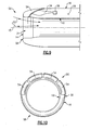
Figures 9 and 10 , anotherexample nacelle assembly 56 includes leadingedge slats 54 disposed only about a portion of the periphery of thenacelle 12. Theleading edge slats 54 also conform to thenacelle 12 when in the retracted position. The outer surface 55 of theslats 54 interfit within theouter surface 16 to provide a substantially continuous surface. Theleading edge slats 54 are segmented circumferentially and extend only partially about theinlet 24 of thenacelle 12. Extending theleading edge slats 54 axially and radially outward about the top part of thenacelle 12 provides desired area and shape changes that in turn modulate airflow and aids in preventing separation of airflow in high angle of attack, high power, and low speed conditions. Further, because each of theleading edge slats 54 are independently actuateable, additional area and inlet shape configurations can be provided to further tailor airflow into thenacelle 12. - The
example nacelle 12 tailors the leading edge and adjusts inlet shape and area to current aircraft operating conditions that in turn improves aircraft engine performance. Although an example of this invention has been disclosed, a worker of ordinary skill in this art would recognize that certain modifications are within the scope of this invention. For that reason, the following claims should be studied to determine the true scope and content of this invention.
Claims (15)
- An aircraft engine nacelle assembly (12) comprising:a leading edge (14) defining an opening area,a plurality of slats (28; 54) disposed at least partially about said leading edge (14), wherein each of said plurality of slats (28; 54) are moveable relative to said leading edge (14) between a first position and as second position to tailor incoming airflow to current operating conditions.
- The assembly as recited in claim 1, wherein said first position comprises said plurality of slats (28; 54) extending radially outward relative to said leading edge (14).
- The assembly as recited in claim 1 or 2 , wherein said second position comprises said plurality of slats (28; 54) extending radially inward relative to said leading edge (14).
- The assembly as recited in claim 1, wherein the first position comprises said slat (28; 54) extending outwardly and axially forward from said leading edge (14) and said second position comprises said slat (28; 54) retracting into and forming a surface of said leading edge (14).
- The assembly as recited in any preceding claim, wherein said plurality of slats (28) extend about an entire circumference of said leading edge (14).
- The assembly as recited in any of claims 1 to 4, wherein said plurality of slats (54) extend about an upper portion of said leading edge (14) .
- The assembly as recited in any preceding claim, wherein each of said plurality of slats (28; 54) are movable independently of each other.
- The assembly as recited in any preceding claim, including at least one actuator (36) for moving said plurality of slats (28; 54) relative to said leading edge (14).
- The assembly as recited in claim 8, wherein said nacelle (12) includes a space between an inner surface and an outer surface within which said actuator (36) is supported.
- An aircraft engine nacelle assembly (12) comprising;
an inner surface defining an air inlet opening (24),
an outer surface spaced radially apart from said inner surface;
a leading edge (14) disposed between said inner and outer surfaces, and
a plurality of slats (28; 54) movable relative to said leading edge (14) for adjusting air flow into said air inlet opening (24). - The nacelle assembly as recited in claim 10, wherein each of said plurality of slats (28; 54) are movable independent of each other between a retracted position and an actuated position.
- The nacelle assembly as recited in claim 10 or 11 , wherein said plurality of slats (28; 54) define a portion of said leading edge (14) when in a retracted position.
- The nacelle assembly as recited in claim 12, wherein said plurality of slats (28; 54) extend radially outward from said leading edge (14) when in an actuated position.
- The nacelle assembly as recited in claim 10 or 11 wherein each of said plurality of slats (28; 54) are movable from a first position that is radially inward of said inner surface and a second position that is radially outboard and axially forward of said inner surface.
- The nacelle assembly as recited in any of claims 10 to 14, wherein said plurality of slats (54) comprise a plurality of segments disposed about an upper portion of said leading edge (14).
Applications Claiming Priority (1)
| Application Number | Priority Date | Filing Date | Title |
|---|---|---|---|
| US11/763,673 US20080308684A1 (en) | 2007-06-15 | 2007-06-15 | Nacelle with articulating leading edge slates |
Publications (2)
| Publication Number | Publication Date |
|---|---|
| EP2003310A2 true EP2003310A2 (en) | 2008-12-17 |
| EP2003310A3 EP2003310A3 (en) | 2011-09-21 |
Family
ID=39714161
Family Applications (1)
| Application Number | Title | Priority Date | Filing Date |
|---|---|---|---|
| EP08252058A Withdrawn EP2003310A3 (en) | 2007-06-15 | 2008-06-16 | Variable geometry nacelle for an aircraft engine |
Country Status (2)
| Country | Link |
|---|---|
| US (1) | US20080308684A1 (en) |
| EP (1) | EP2003310A3 (en) |
Cited By (5)
| Publication number | Priority date | Publication date | Assignee | Title |
|---|---|---|---|---|
| EP2631181A3 (en) * | 2012-02-24 | 2014-08-20 | Rohr, Inc. | Nacelle |
| CN107939526A (en) * | 2016-10-12 | 2018-04-20 | 通用电气公司 | Inlet cowlings for turbine engines |
| DE102017106954A1 (en) * | 2017-03-31 | 2018-10-04 | Rolls-Royce Deutschland Ltd & Co Kg | Engine nacelle for a turbofan engine |
| EP3421370A1 (en) * | 2017-06-26 | 2019-01-02 | The Boeing Company | Translating turning vanes for a nacelle inlet |
| EP3421373A1 (en) * | 2017-06-26 | 2019-01-02 | The Boeing Company | Rotating devices for mitigation of adverse flow conditions in an ultra-short nacelle inlet |
Families Citing this family (9)
| Publication number | Priority date | Publication date | Assignee | Title |
|---|---|---|---|---|
| US20080310956A1 (en) * | 2007-06-13 | 2008-12-18 | Jain Ashok K | Variable geometry gas turbine engine nacelle assembly with nanoelectromechanical system |
| US20100284791A1 (en) * | 2009-05-11 | 2010-11-11 | Robert Jesse Flores | Apparatuses, systems, and methods for preventing foreign objects from being ingested into a jet engine |
| US10501196B2 (en) | 2016-09-30 | 2019-12-10 | General Electric Company | Nacelle for an aircraft aft fan |
| US20180208297A1 (en) | 2017-01-20 | 2018-07-26 | General Electric Company | Nacelle for an aircraft aft fan |
| US10752371B2 (en) * | 2016-09-30 | 2020-08-25 | General Electric Company | Translating nacelle wall for an aircraft tail mounted fan section |
| US11584509B2 (en) * | 2019-06-27 | 2023-02-21 | Supra Lumina Technologies Inc. | Axial flow ducted fan with a movable section |
| FR3114615B1 (en) * | 2020-09-30 | 2024-01-12 | Safran Aircraft Engines | AIR INLET HANDLE FILTERING DISTORTION FOR A NACELLE OF AN AIRCRAFT PROPULSION ASSEMBLY |
| US11629651B2 (en) * | 2020-11-17 | 2023-04-18 | General Electric Company | Gas turbine engine having a turbomachine and an electric motor coupled to a propeller |
| KR102760903B1 (en) * | 2024-01-25 | 2025-02-03 | 에어빌리티 주식회사 | Transformable fan jet |
Family Cites Families (20)
| Publication number | Priority date | Publication date | Assignee | Title |
|---|---|---|---|---|
| US3222863A (en) * | 1963-10-07 | 1965-12-14 | Boeing Co | Aerodynamic inlet |
| US3532129A (en) * | 1969-02-05 | 1970-10-06 | Rolls Royce | Silencing of gas turbine engines |
| US3664612A (en) * | 1969-12-22 | 1972-05-23 | Boeing Co | Aircraft engine variable highlight inlet |
| US3618876A (en) * | 1969-12-22 | 1971-11-09 | Boeing Co | Aircraft engine leading edge auxiliary air inlet |
| US3575259A (en) * | 1970-04-10 | 1971-04-20 | Boeing Co | Retractable noise suppression system |
| GB1336724A (en) * | 1970-11-03 | 1973-11-07 | Secr Defence | Gas turbine engine air intakes |
| US3770228A (en) * | 1971-12-08 | 1973-11-06 | Lockheed Aircraft Corp | Air inlet flap |
| US3883095A (en) * | 1973-09-19 | 1975-05-13 | Nasa | Reversed cowl flap inlet thrust augmentor |
| US4722357A (en) * | 1986-04-11 | 1988-02-02 | United Technologies Corporation | Gas turbine engine nacelle |
| DE3720318A1 (en) * | 1987-06-19 | 1989-01-05 | Mtu Muenchen Gmbh | GONDOLA FOR JET ENGINES |
| US5000399A (en) * | 1990-02-23 | 1991-03-19 | General Electric Company | Variable contour annular air inlet for an aircraft engine nacelle |
| GB9025023D0 (en) * | 1990-11-16 | 1991-01-02 | Rolls Royce Plc | Engine nacelle |
| US6089505A (en) * | 1997-07-22 | 2000-07-18 | Mcdonnell Douglas Corporation | Mission adaptive inlet |
| US6390418B1 (en) * | 1999-02-25 | 2002-05-21 | United Technologies Corporation | Tangentially directed acoustic jet controlling boundary layer |
| US6379110B1 (en) * | 1999-02-25 | 2002-04-30 | United Technologies Corporation | Passively driven acoustic jet controlling boundary layers |
| TW409738U (en) * | 1999-04-08 | 2000-10-21 | Lu Mau Wen | Washing machine of which the water level can be changed automatically |
| US6588709B1 (en) * | 2002-03-20 | 2003-07-08 | The Boeing Company | Apparatus for variation of a wall skin |
| US6655632B1 (en) * | 2002-08-27 | 2003-12-02 | General Electric Company | System and method for actively changing an effective flow-through area of an inlet region of an aircraft engine |
| US6910327B2 (en) * | 2003-07-28 | 2005-06-28 | The Boeing Company | Apparatus and methods for varying inlet lip geometry of a jet engine inlet |
| US6959552B2 (en) * | 2004-03-18 | 2005-11-01 | Pratt & Whitney Canada Corp. | Gas turbine inlet flow straightener |
-
2007
- 2007-06-15 US US11/763,673 patent/US20080308684A1/en not_active Abandoned
-
2008
- 2008-06-16 EP EP08252058A patent/EP2003310A3/en not_active Withdrawn
Cited By (10)
| Publication number | Priority date | Publication date | Assignee | Title |
|---|---|---|---|---|
| EP2631181A3 (en) * | 2012-02-24 | 2014-08-20 | Rohr, Inc. | Nacelle |
| CN107939526A (en) * | 2016-10-12 | 2018-04-20 | 通用电气公司 | Inlet cowlings for turbine engines |
| CN107939526B (en) * | 2016-10-12 | 2020-04-28 | 通用电气公司 | Inlet cowl for a turbine engine |
| US10837362B2 (en) | 2016-10-12 | 2020-11-17 | General Electric Company | Inlet cowl for a turbine engine |
| US11555449B2 (en) | 2016-10-12 | 2023-01-17 | General Electric Company | Inlet cowl for a turbine engine |
| DE102017106954A1 (en) * | 2017-03-31 | 2018-10-04 | Rolls-Royce Deutschland Ltd & Co Kg | Engine nacelle for a turbofan engine |
| US11149637B2 (en) | 2017-03-31 | 2021-10-19 | Rolls-Royce Deutschland Ltd & Co Kg | Nacelle for a turbofan engine |
| EP3421370A1 (en) * | 2017-06-26 | 2019-01-02 | The Boeing Company | Translating turning vanes for a nacelle inlet |
| EP3421373A1 (en) * | 2017-06-26 | 2019-01-02 | The Boeing Company | Rotating devices for mitigation of adverse flow conditions in an ultra-short nacelle inlet |
| JP2019006374A (en) * | 2017-06-26 | 2019-01-17 | ザ・ボーイング・カンパニーThe Boeing Company | Rotating device for mitigating adverse flow conditions at ultrashort nacelle inlet |
Also Published As
| Publication number | Publication date |
|---|---|
| US20080308684A1 (en) | 2008-12-18 |
| EP2003310A3 (en) | 2011-09-21 |
Similar Documents
| Publication | Publication Date | Title |
|---|---|---|
| EP2003310A2 (en) | Variable geometry nacelle for an aircraft engine | |
| EP2074304B1 (en) | Gas turbine engine having tri-body variable area fan nozzle and thrust reverser | |
| US5000399A (en) | Variable contour annular air inlet for an aircraft engine nacelle | |
| EP2134949B1 (en) | Fan variable area nozzle for a gas turbine engine fan nacelle with drive ring actuation system | |
| EP2011987B1 (en) | Gas turbine engine and corresponding method of controlling | |
| EP2214959B1 (en) | Actuation system for leading edge high-lift device | |
| CA2767294C (en) | Craft and method for assembling craft with controlled spin | |
| CA2682372C (en) | Aircraft with aerodynamic lift generating device | |
| EP3165718B1 (en) | Gas turbine engine and method of varying an effective fan nozzle exit area of a gas turbine engine | |
| EP2074322B1 (en) | Turbofan engine | |
| US20090003997A1 (en) | Variable shape inlet section for a nacelle assembly of a gas turbine engine | |
| EP3402712B1 (en) | Vehicle rear wing with adaptive section and extendable flap | |
| EP2333282A2 (en) | Variable area fan nozzle stiffeners and placement | |
| EP2157299A1 (en) | Nacelle assembly for a gas turbine engine with variable shape inlet section, corresponding gas turbine engine and operating method | |
| EP1988014A2 (en) | Ducted fan air vehicle with deployable wings | |
| EP3301018A1 (en) | System for driving and guiding of a multifunctional trailing edge control surface on an aircraft | |
| US20230242244A1 (en) | Axial flow ducted fan with a movable section | |
| CN111319778A (en) | Turbofan engine and aircraft | |
| EP2074319B1 (en) | Gas turbine engine with a variable exit area fan nozzle, nacelle assembly of such a engine, and corresponding operating method | |
| EP2987991A1 (en) | Fan nozzle with thrust reversing and variable area function | |
| US11878786B2 (en) | Propulsion system for an aircraft | |
| EP2395222B1 (en) | Gas turbine engine system and corresponding controlling method | |
| EP4339435A1 (en) | Aircraft propulsion system with variable area inlet | |
| EP4339436A1 (en) | Aircraft propulsion system with variable area inlet | |
| EP2074303B1 (en) | Core cowl airfoil for a gas turbine engine |
Legal Events
| Date | Code | Title | Description |
|---|---|---|---|
| PUAI | Public reference made under article 153(3) epc to a published international application that has entered the european phase |
Free format text: ORIGINAL CODE: 0009012 |
|
| AK | Designated contracting states |
Kind code of ref document: A2 Designated state(s): AT BE BG CH CY CZ DE DK EE ES FI FR GB GR HR HU IE IS IT LI LT LU LV MC MT NL NO PL PT RO SE SI SK TR |
|
| AX | Request for extension of the european patent |
Extension state: AL BA MK RS |
|
| PUAL | Search report despatched |
Free format text: ORIGINAL CODE: 0009013 |
|
| AK | Designated contracting states |
Kind code of ref document: A3 Designated state(s): AT BE BG CH CY CZ DE DK EE ES FI FR GB GR HR HU IE IS IT LI LT LU LV MC MT NL NO PL PT RO SE SI SK TR |
|
| AX | Request for extension of the european patent |
Extension state: AL BA MK RS |
|
| RIC1 | Information provided on ipc code assigned before grant |
Ipc: F02K 3/06 20060101ALI20110816BHEP Ipc: F02C 7/042 20060101AFI20110816BHEP |
|
| AKY | No designation fees paid | ||
| REG | Reference to a national code |
Ref country code: DE Ref legal event code: R108 |
|
| REG | Reference to a national code |
Ref country code: DE Ref legal event code: R108 Effective date: 20120530 |
|
| STAA | Information on the status of an ep patent application or granted ep patent |
Free format text: STATUS: THE APPLICATION IS DEEMED TO BE WITHDRAWN |
|
| 18D | Application deemed to be withdrawn |
Effective date: 20120322 |