EP2002809B1 - Food intake restriction device - Google Patents
Food intake restriction device Download PDFInfo
- Publication number
- EP2002809B1 EP2002809B1 EP08075768A EP08075768A EP2002809B1 EP 2002809 B1 EP2002809 B1 EP 2002809B1 EP 08075768 A EP08075768 A EP 08075768A EP 08075768 A EP08075768 A EP 08075768A EP 2002809 B1 EP2002809 B1 EP 2002809B1
- Authority
- EP
- European Patent Office
- Prior art keywords
- energy
- restriction
- patient
- motor
- implantable
- Prior art date
- Legal status (The legal status is an assumption and is not a legal conclusion. Google has not performed a legal analysis and makes no representation as to the accuracy of the status listed.)
- Expired - Lifetime
Links
Images
Classifications
-
- A—HUMAN NECESSITIES
- A61—MEDICAL OR VETERINARY SCIENCE; HYGIENE
- A61F—FILTERS IMPLANTABLE INTO BLOOD VESSELS; PROSTHESES; DEVICES PROVIDING PATENCY TO, OR PREVENTING COLLAPSING OF, TUBULAR STRUCTURES OF THE BODY, e.g. STENTS; ORTHOPAEDIC, NURSING OR CONTRACEPTIVE DEVICES; FOMENTATION; TREATMENT OR PROTECTION OF EYES OR EARS; BANDAGES, DRESSINGS OR ABSORBENT PADS; FIRST-AID KITS
- A61F5/00—Orthopaedic methods or devices for non-surgical treatment of bones or joints; Nursing devices; Anti-rape devices
- A61F5/0003—Apparatus for the treatment of obesity; Anti-eating devices
- A61F5/0013—Implantable devices or invasive measures
- A61F5/005—Gastric bands
- A61F5/0053—Gastric bands remotely adjustable
-
- A—HUMAN NECESSITIES
- A61—MEDICAL OR VETERINARY SCIENCE; HYGIENE
- A61F—FILTERS IMPLANTABLE INTO BLOOD VESSELS; PROSTHESES; DEVICES PROVIDING PATENCY TO, OR PREVENTING COLLAPSING OF, TUBULAR STRUCTURES OF THE BODY, e.g. STENTS; ORTHOPAEDIC, NURSING OR CONTRACEPTIVE DEVICES; FOMENTATION; TREATMENT OR PROTECTION OF EYES OR EARS; BANDAGES, DRESSINGS OR ABSORBENT PADS; FIRST-AID KITS
- A61F5/00—Orthopaedic methods or devices for non-surgical treatment of bones or joints; Nursing devices; Anti-rape devices
- A61F5/0003—Apparatus for the treatment of obesity; Anti-eating devices
Definitions
- the present invention relates to a food intake restriction device for forming a stoma opening in the stomach or esophagus of a patient, as defined in claim 1, the device comprising an elongated restriction member, forming means for forming the elongated restriction member into at least a substantially closed loop around the patient's stomach or esophagus, said loop defining a restriction opening, and an adjustment means for adjusting the restriction member in said loop to change the size of said restriction opening.
- patient includes an animal or a human being.
- Food intake restriction devices in the form of gastric banding devices, in which a band encircles a portion of a patient's stomach to restrict the food intake of the patient, have been used in surgery for morbid obesity to form a small gastric pouch above the band and a reduced stoma opening in the stomach. Although such a band is applied around the stomach to obtain an optimal stoma opening during surgery, some prior gastric banding devices are provided with an adjustment means enabling a minor post-operation adjustment of the size of the stoma opening. In all such prior art devices such as disclosed in U.S. Patent No. 4,592,339 , European Patent No.
- the adjustment means typically comprises an inflatable cavity in the band and an injection port in fluid connection with the inflatable cavity for adding fluid to or withdrawing fluid from the latter.
- the band is made of silicone rubber which is a material approved for implantation and the fluid is a liquid such as an isotonic salt solution.
- the volume of the gastric pouch above the band increases in size up to ten times after operation. Therefore the pouch volume during surgery needs to be very small, approximately 7 ml.
- the stoma initially needs to be relatively large and later needs to be substantially reduced, as the pouch volume increases.
- the cavity in the band has to be relatively large and is defined by a thin flexible wall, normally made of silicone material.
- the size of the stoma opening has to be gradually reduced during the first year after surgery as the gastric pouch increases in size. As indicated above, the reduction of the stoma opening using the prior art devices is achieved by adding liquid to the cavity of the band via the injection port to expand the band radially inwardly.
- a great disadvantage of repeatedly injecting liquid via the injection port is the increased risk of the patient getting an infection in the body area surrounding the injection port. If such an infection occurs the injection port has to be surgically removed from the patient. Moreover, such an infection might be spread along the tube interconnecting the injection port and the band to the stomach, causing even more serious complications. Thus, the stomach might be infected where it is in contact with the band, which might result in the band migrating through the wall of the stomach. Also, it is uncomfortable for the patient when the necessary, often many, post-operation adjustments of the stoma opening are carried out using an injection needle penetrating the skin of the patient into the injection port.
- European patent application EP 0 876 808 which qualifies as prior art under Art 54(3) EPC, discloses a device which includes an adjustable strap for implanting around the stomach.
- the strap has a variable volume cavity filled with a liquid.
- the volume of liquid in teh cavity is adjusted by a system which includes a control box that is connected to the cavity and implanted in the patient's body.
- the control box contains a battery, an electronic control unit and an electronically driven pump.
- FR 2 756 485 discloses a prosthetic urinary sphincter with an external control.
- the sphincter includes a ring-shaped balloon which is arranged inside an inextensible sheath enclosing the corporeal duct.
- a pump positioned within a fluid circuit is controlled by electromagnetic induction by means of an antenna located inside the body.
- WO 96/01597 discloses a vessel occlusive prosthesis for occluding a fluid conveying vessel.
- the prosthesis includes an elongated member at least partially encircling the vessel, and means connected to the elongated member for applying tension to the elongated member.
- US 3,750,194 discloses a device for closing a natural or implanted body passage which uses an implantable fluid reservoir and a distensible member that is adapted to be connected to the passage.
- An implantable pump is connected to the fluid reservoir and the distensible member for pumping fluid from the reservoir to the distensible member
- GB 1,174,814 discloses a device for occluding ducts.
- the device is operated either manually or by facilities located outside of the body
- An object of the invention is to provide a food intake restriction device for forming a stoma opening in the stomach or esophagus of a patient which permits regular post-operation adjustments that are comfortable for the patient.
- Another object of the present invention is to provide a food intake restriction device for forming a stoma opening in the stomach or esophagus of a patient which is easy to adjust and does not require the use of an injection needle for accomplishing post-operation adjustments of the stoma opening.
- the remote control means may advantageously be capable of obtaining information on the size of the restriction opening and to command the adjustment means to adjust the restriction member in response to obtained information.
- An implantable motor may suitably be provided for operating the adjustment means and said means for wireless transfer of energy may be adapted to directly power the motor with transferred energy.
- the energy transferred by said means for transfer of energy may comprise wave signals, an electric field or a magnetic field.
- the wireless remote control means comprises separate signal transmitting means and implantable signal receiving means.
- the signal receiving means comprises a control unit adapted to control the adjustment means in response to signals from the signal transmitting means.
- the signal transmitting and signal receiving means may be adapted to transmit and receive signals in the form of digital pulses, which may comprise a magnetic or electric field.
- the signal transmitting and signal receiving means may be adapted to transmit and receive wave signals, which may comprise electromagnetic waves, sound waves or carrier waves for remote control signals.
- the food intake restriction device further comprises an implantable energizer unit for providing energy to energy consuming components of the device to be implanted in the patient, such as electronic circuits and/or a motor for operating the adjustment means.
- the control unit may be adapted to power such an implanted motor with energy provided by the energizer unit in response to signals received from the signal transmitting means.
- Any known or conventional signal transmitting or receiving device that is suitable for use with a human or mammal patient may be provided as the signal transmitting or receiving means.
- the signals may comprise electromagnetic waves, such as infrared light, visible light, laser light, micro waves, or sound waves, such as ultrasonic waves or infrasonic waves, or any other type of wave signals.
- the signals may also comprise electric or magnetic fields, or pulses. All of the above-mentioned signals may comprise digital signals.
- the motor may be any type of motor, such as a pneumatic, hydraulic or electric motor and the energizer unit may be adapted to power the motor with pressurized gas or liquid, or electrical energy, depending on the type of motor. Where the motor is an electric motor, it may power pneumatic or hydraulic equipment.
- the energizer unit comprises a power supply and the control unit is adapted to power the motor with energy from the power supply.
- the power supply is an electric power supply
- the motor is an electric motor.
- the energizer unit is adapted to transfer energy from the signals, as they are transmitted to the signal receiving means, into electric energy for powering the implanted electronic components.
- the energizer unit may be adapted to transfer the energy from the signals into direct or alternating current.
- the energizer unit may also power the motor with the transferred energy.
- the control unit is adapted to directly power the electric motor with electric energy, as the energizer unit transfers the signal energy into the electric energy.
- the energizer unit may comprise a rechargeable electric power supply for storing the electric energy obtained and the control unit be adapted to power the electric motor with energy from the rechargeable electric power supply in response to signals received from the signal transmitting means.
- the rechargeable power supply can be charged over a relatively long time (e.g. a few seconds up to a half hour) without powering the electric motor.
- the control unit powers the electric motor with energy from the charged power supply to operate the adjustment means, so that a desired change of the patient's stoma opening is achieved. If the capacity of the power supply is insignificant to achieve the necessary adjustment in one single operating step, the above steps may conveniently be repeated until the desired adjustment is achieved.
- the electric power supply suitably comprises an inexpensive simple capacitor.
- the electric motor may be a stepping motor.
- the signal transmitting means may be adapted to transmit electromagnetic wave signals and the energizer unit be adapted to draw radiant energy from the electromagnetic wave signals, as they are transmitted to the signal receiving means, and transfer the radiant energy into electric energy.
- the signal transmitting means may be adapted to transmit electromagnetic wave signals and the energizer unit be adapted to draw radiant energy from the electromagnetic wave signals, as they are transmitted to the signal receiving means, and to transfer the radiant energy into said current.
- the energizer unit suitably comprises a coil of the signal receiving means for inducing an alternating current as electromagnetic wave signals are transmitted through the coil and a rectifier for rectifying the alternating current. The rectified current is used for charging the rechargeable power source.
- the signal transmitting and receiving means may solely be used for control signals and further signal transmitting and receiving means be provided for transferring signal energy to implanted components.
- the advantage is obtained that the two systems can be designed optimally for their respective purposes, namely to transmit control signals and to transfer energy from signals.
- the adjustment means comprises an inflatable cavity of a restriction member
- the adjustment means comprises an elongated restriction member which is non-inflatable, in order to avoid the risk of fluid leaking from the cavity.
- an adjustment means which is designed to mechanically adjust the non-inflatable restriction member.
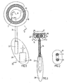
- Figs. 1-3 show an example of a part of the food intake restriction device of the invention, comprising a circular resilient non-inflatable restriction member 2 with two overlapping end portions 4,6.
- the restriction member 2 defines a substantially circular restriction opening and is enclosed in an elastic soft hose 8 except at a releasable and lockable joint 10 of the restriction member 2, which when released enables application of the restriction member 2 with its hose 8 around the esophagus or stomach of a patient in a surgical procedure.
- All of the in body components are desirably of bio-compatible material or covered with bio-compatible material.
- An adjustment means 12 mechanically adjusts the longitudinal extension of the restriction member 2 to change the size of said restriction opening.
- the adjustment means may comprise any known or conventional mechanical device for this purpose.
- the illustrated embodiment of the device 12 comprises a pulley 14 in frictional engagement with the overlapping end portions 4,6.
- the pulley 14 is journalled on a holder 16 placed in the hose 8 and provided with two counter pressure rollers 18,20 pressing the respective end portions 4, 6 against the pulley 14 to increase the frictional engagement therebetween.
- An electric motor 22 is connected to the pulley 14 via a long flexible drive shaft 24 and is moulded together with an energizer unit 26 in a body 28 of silicone.
- the length of the flexible drive shaft 24 is selected so that the body 28 can be placed in a desired position in the abdomen of the patient. All components are of bio-compatible material, or covered with bio-compatible material.
- the energizer unit 26 is controlled to power the electric motor 22 either to rotate the pulley 14 in one direction to reduce the diameter of the circular restriction member 2 or to rotate the pulley 14 in the opposite direction to increase the diameter of the restriction member 2.
- the implantable part of the device described above alternatively may be one of a variety of different adjustable designs.
- the elongated restriction member may be inflatable by a fluid, which is pumped to and from the restriction member by a pump operated by the motor 22.
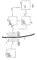
- Fig. 4 shows the basic parts of an exemplary remote control system of the device of the invention including the electric motor 22.
- This remote control system is based on the transmission of electromagnetic wave signals, often of high frequencies on the order of 100 kHz - 1 gHz, through the skin 30 of the patient.
- any known or developed remote control system may be utilized; electromagnetic wave signals do not need to be transmitted.
- all parts placed to the left of the skin 30 are located outside the patient's body and are thus not implanted, whereas all parts placed to the right of the skin 30 are implanted.
- An external signal transmitting antenna 32 is to be positioned close to a signal receiving antenna 34 implanted close to the skin 30.
- the receiving antenna 34 may be placed, for example, inside the abdomen of the patient.
- the receiving antenna 34 may comprise a coil, approximately 1-100 mm, preferably 25 mm in diameter, wound with a very thin wire and tuned with a capacitor to a specific high frequency.
- a small coil is chosen if it is to be implanted under the skin of the patient and a large coil is chosen if it is to be implanted in the abdomen of the patient.
- the transmitting antenna 32 comprises a coil having about the same size as the coil of the receiving antenna 34 but wound with a thick wire that can handle the larger currents that is necessary.
- the coil of the transmitting antenna 32 is tuned to the same specific high frequency as the coil of the receiving antenna 34.
- An external control unit 36 preferably comprises a microprocessor, a high frequency electromagnetic wave signal generator and a power amplifier.
- the microprocessor of the control unit 36 is adapted to switch the generator on/off and to modulate signals generated by the generator to send digital information via the power amplifier and the antennas 32,34 to an implanted control unit 38.
- digital signal codes are used.
- a conventional keypad 37 placed on the external control unit 36 is connected to the microprocessor thereof. The keypad 37 is used to order the microprocessor to send digital signals to either increase or decrease the size of the restriction opening 3 defined by the loop of the restriction member 2.
- the microprocessor starts a command by applying a high frequency signal on the antenna 32.
- commands are sent to increase or decrease the size of said restriction opening of the restriction member 2 in predefined steps.
- the commands are preferably sent as digital packets in the form illustrated below. Start pattern, Command, Count, Checksum, 8 bits 8 bits 8 bits 8 bits 8 bits.
- the commands are sent continuously during a rather long time period, e.g. about 30 seconds or more.
- the Count byte is increased by one to allow the implanted control unit 38 to decode and understand that another step is demanded by the external control unit 36. If any part of the digital packet is erroneous, its content is simply ignored.
- the implanted energizer unit 26 draws energy from the high frequency electromagnetic wave signals received by the receiving antenna 34.
- the energizer unit 26 stores the energy in a power supply, such as a large capacitor, powers the control unit 38 and powers the electric motor 22 via a line 42.
- the control unit 38 comprises a demodulator and a microprocessor.
- the demodulator demodulates digital signals sent from the external control unit 36.
- the microprocessor of the control unit 38 receives the digital packet, decodes it and, provided that the power supply of the energizer unit 26 has sufficient energy stored, sends a signal via a signal line 44 to the motor 22 to either increase or decrease the size of the restriction opening 3 of the restriction member 2 depending on the received command code.
- the external control unit 36 comprises a microprocessor 46, a signal generator 48 and a power amplifier 50 connected thereto.
- the microprocessor 46 switches the signal generator 48 on/off and to modulate signals generated by the signal generator 48 with digital commands that are sent to implanted components (to the right of skin 30 in Fig.5 ) of the implantable device.
- the power amplifier 50 amplifies the signals and sends them to the external signal transmitting antenna 32.
- the antenna 32 is connected in parallel with a capacitor 52 to form a resonant circuit tuned to the frequency generated by the signal generator 48.
- the implanted signal receiving antenna coil 34 forms together with a capacitor 54 a resonant circuit that is tuned to the same frequency as the transmitting antenna 32.
- the signal receiving antenna coil 34 induces a current from the received high frequency electromagnetic waves and a rectifying diode 60 rectifies the induced current, which charges a storage capacitor 58.
- a coil 56 connected between the antenna coil 34 and the diode 60 prevents the capacitor 58 and the diode 60 from loading the circuit of the signal receiving antenna 34 at higher frequencies.
- the coil 56 makes it possible to charge the capacitor 58 and to transmit digital information using amplitude modulation.
- a capacitor 62 and a resistor 64 connected in parallel and a diode 66 forms a detector used to detect amplitude modulated digital information.
- a filter circuit is formed by a resistor 68 connected in series with a resistor 70, in turn connected in series with a capacitor 72, in turn connected in series with the resistor 68 via ground, and a capacitor 74, one terminal of which is connected between the resistors 68,70 and the other terminal of which is connected between the diode 66 and the circuit formed by the capacitor 62 and resistor 64.
- the filter circuit is used to filter out undesired low and high frequencies.
- the detected and filtered signals are fed to an implanted microprocessor 76 that decodes the digital information and controls the motor 22 via an H-bridge 78 comprising transistors 80,82,84 and 86.
- the motor 22 can be driven in two opposite directions by the H-bridge 78.
- the microprocessor 76 also monitors the amount of stored energy in the storage capacitor 58. Before sending signals to activate the motor 22, the microprocessor 76 checks whether the energy stored in the storage capacitor 58 is enough. If the stored energy is not enough to perform the requested operation, the microprocessor 76 waits for the received signals to charge the storage capacitor 58 before activating the motor 22.
- the remote control means it is possible to programme various sizes of the restriction opening which are to be set by the adjustment means depending on the time of the day.
- the restriction opening may be relatively large at night, which may be beneficial with respect to the patient's well-being.
- Means may also be provided for sensing the actual size of the restriction opening so that the adjustment means can be controlled by the remote control means to adjust the restriction opening in response to such a sensing means.
- control units may be replaced by discrete components.
- the power amplifier of the external control unit may be omitted if the signals generated by the signal generator are strong enough. Therefore, the invention is to be accorded the broadest interpretation of the appended claims to encompass all equivalent structures and assemblies.
- One further advantage with this invention is that there may be a night button on the remote control setting the adjustment means in a position with a larger stoma diameter during the night, thus avoiding vomiting or nausa.
Abstract
Description
- The present invention relates to a food intake restriction device for forming a stoma opening in the stomach or esophagus of a patient, as defined in claim 1, the device comprising an elongated restriction member, forming means for forming the elongated restriction member into at least a substantially closed loop around the patient's stomach or esophagus, said loop defining a restriction opening, and an adjustment means for adjusting the restriction member in said loop to change the size of said restriction opening. The term "patient" includes an animal or a human being.
- Food intake restriction devices in the form of gastric banding devices, in which a band encircles a portion of a patient's stomach to restrict the food intake of the patient, have been used in surgery for morbid obesity to form a small gastric pouch above the band and a reduced stoma opening in the stomach. Although such a band is applied around the stomach to obtain an optimal stoma opening during surgery, some prior gastric banding devices are provided with an adjustment means enabling a minor post-operation adjustment of the size of the stoma opening. In all such prior art devices such as disclosed in
U.S. Patent No. 4,592,339 , European Patent No.0611561 and International Patent ApplicationWO 94/27504 - It has also been found that the volume of the gastric pouch above the band increases in size up to ten times after operation. Therefore the pouch volume during surgery needs to be very small, approximately 7 ml. To enable the patient to feed the stomach with sufficient nutrition immediately after an operation considering such a small gastric pouch, the stoma initially needs to be relatively large and later needs to be substantially reduced, as the pouch volume increases. To be able to achieve a significant range of adjustment of the band, the cavity in the band has to be relatively large and is defined by a thin flexible wall, normally made of silicone material. Furthermore, the size of the stoma opening has to be gradually reduced during the first year after surgery as the gastric pouch increases in size. As indicated above, the reduction of the stoma opening using the prior art devices is achieved by adding liquid to the cavity of the band via the injection port to expand the band radially inwardly.
- A great disadvantage of repeatedly injecting liquid via the injection port is the increased risk of the patient getting an infection in the body area surrounding the injection port. If such an infection occurs the injection port has to be surgically removed from the patient. Moreover, such an infection might be spread along the tube interconnecting the injection port and the band to the stomach, causing even more serious complications. Thus, the stomach might be infected where it is in contact with the band, which might result in the band migrating through the wall of the stomach. Also, it is uncomfortable for the patient when the necessary, often many, post-operation adjustments of the stoma opening are carried out using an injection needle penetrating the skin of the patient into the injection port.
- It may happen that the patient swallows pieces of food too large to pass through the restricted stoma opening. If that occurs the patient has to visit a doctor who can remove the food pieces, if the band design so permits, by withdrawing some liquid from the band to enlarge the stoma opening to allow the food pieces to pass the stoma. Then, the doctor has to add liquid to the band in order to regain the restricted stoma opening. Again, these measures require the use of an injection needle penetrating the skin of the patient, which is uncomfortable for the patient.
- European patent application
EP 0 876 808 , which qualifies as prior art under Art 54(3) EPC, discloses a device which includes an adjustable strap for implanting around the stomach. The strap has a variable volume cavity filled with a liquid. The volume of liquid in teh cavity is adjusted by a system which includes a control box that is connected to the cavity and implanted in the patient's body. The control box contains a battery, an electronic control unit and an electronically driven pump. -
FR 2 756 485 -
WO 96/01597 -
US 3,750,194 discloses a device for closing a natural or implanted body passage which uses an implantable fluid reservoir and a distensible member that is adapted to be connected to the passage. An implantable pump is connected to the fluid reservoir and the distensible member for pumping fluid from the reservoir to the distensible member -
GB 1,174,814 - An object of the invention is to provide a food intake restriction device for forming a stoma opening in the stomach or esophagus of a patient which permits regular post-operation adjustments that are comfortable for the patient.
- Another object of the present invention is to provide a food intake restriction device for forming a stoma opening in the stomach or esophagus of a patient which is easy to adjust and does not require the use of an injection needle for accomplishing post-operation adjustments of the stoma opening.
- These objects are obtained by a food intake restriction device as recited in the claims.
- The remote control means may advantageously be capable of obtaining information on the size of the restriction opening and to command the adjustment means to adjust the restriction member in response to obtained information.
- An implantable motor may suitably be provided for operating the adjustment means and said means for wireless transfer of energy may be adapted to directly power the motor with transferred energy. The energy transferred by said means for transfer of energy may comprise wave signals, an electric field or a magnetic field.
- Preferably, the wireless remote control means comprises separate signal transmitting means and implantable signal receiving means. The signal receiving means comprises a control unit adapted to control the adjustment means in response to signals from the signal transmitting means. For example, the signal transmitting and signal receiving means may be adapted to transmit and receive signals in the form of digital pulses, which may comprise a magnetic or electric field. Alternatively, which is preferred, the signal transmitting and signal receiving means may be adapted to transmit and receive wave signals, which may comprise electromagnetic waves, sound waves or carrier waves for remote control signals.
- The food intake restriction device further comprises an implantable energizer unit for providing energy to energy consuming components of the device to be implanted in the patient, such as electronic circuits and/or a motor for operating the adjustment means. The control unit may be adapted to power such an implanted motor with energy provided by the energizer unit in response to signals received from the signal transmitting means. Any known or conventional signal transmitting or receiving device that is suitable for use with a human or mammal patient may be provided as the signal transmitting or receiving means. The signals may comprise electromagnetic waves, such as infrared light, visible light, laser light, micro waves, or sound waves, such as ultrasonic waves or infrasonic waves, or any other type of wave signals. The signals may also comprise electric or magnetic fields, or pulses. All of the above-mentioned signals may comprise digital signals.
- The motor may be any type of motor, such as a pneumatic, hydraulic or electric motor and the energizer unit may be adapted to power the motor with pressurized gas or liquid, or electrical energy, depending on the type of motor. Where the motor is an electric motor, it may power pneumatic or hydraulic equipment.
- In accordance with a first particular embodiment of the invention, the energizer unit comprises a power supply and the control unit is adapted to power the motor with energy from the power supply. Preferably, the power supply is an electric power supply, and the motor is an electric motor.
- In accordance with a second, preferred, particular embodiment of the invention, the energizer unit is adapted to transfer energy from the signals, as they are transmitted to the signal receiving means, into electric energy for powering the implanted electronic components. For example, the energizer unit may be adapted to transfer the energy from the signals into direct or alternating current.
- In case there is an implanted electric motor for operating the adjustment means the energizer unit may also power the motor with the transferred energy. Advantageously, the control unit is adapted to directly power the electric motor with electric energy, as the energizer unit transfers the signal energy into the electric energy. This embodiment is particularly simple and does not require any recurrent invasive measures for exchanging empty power supplies, such as batteries, that is required in the first embodiment described above.
- To expand the field of application of the second preferred embodiment to adjustment means of the type that requires more, but still relatively low, power for its operation, the energizer unit may comprise a rechargeable electric power supply for storing the electric energy obtained and the control unit be adapted to power the electric motor with energy from the rechargeable electric power supply in response to signals received from the signal transmitting means. In an initial charging step the rechargeable power supply can be charged over a relatively long time (e.g. a few seconds up to a half hour) without powering the electric motor. In a following operating step, when the power supply has been charged with sufficient energy, the control unit powers the electric motor with energy from the charged power supply to operate the adjustment means, so that a desired change of the patient's stoma opening is achieved. If the capacity of the power supply is insignificant to achieve the necessary adjustment in one single operating step, the above steps may conveniently be repeated until the desired adjustment is achieved.
- The electric power supply suitably comprises an inexpensive simple capacitor. In this case, the electric motor may be a stepping motor.
- In connection with the second preferred embodiment the signal transmitting means may be adapted to transmit electromagnetic wave signals and the energizer unit be adapted to draw radiant energy from the electromagnetic wave signals, as they are transmitted to the signal receiving means, and transfer the radiant energy into electric energy.
- In the above-described embodiments of the invention, the signal transmitting means may be adapted to transmit electromagnetic wave signals and the energizer unit be adapted to draw radiant energy from the electromagnetic wave signals, as they are transmitted to the signal receiving means, and to transfer the radiant energy into said current. The energizer unit suitably comprises a coil of the signal receiving means for inducing an alternating current as electromagnetic wave signals are transmitted through the coil and a rectifier for rectifying the alternating current. The rectified current is used for charging the rechargeable power source.
- Alternatively, the signal transmitting and receiving means may solely be used for control signals and further signal transmitting and receiving means be provided for transferring signal energy to implanted components. By such a double system of signal transmitting and receiving means the advantage is obtained that the two systems can be designed optimally for their respective purposes, namely to transmit control signals and to transfer energy from signals.
- Although the above-described embodiments of the invention may very well be implemented in connection with the prior types of food intake restriction devices discussed above, in which the adjustment means comprises an inflatable cavity of a restriction member, it is preferred to use an elongated restriction member which is non-inflatable, in order to avoid the risk of fluid leaking from the cavity. Furthermore, it is preferred to use an adjustment means which is designed to mechanically adjust the non-inflatable restriction member.
- The invention is described in more detail in the following by way of example with reference to the accompanying drawings, in which
-
Figure 1 is a schematic cross-sectional view of a part of the food intake restriction device in accordance with the present invention; -
Figures 2 and 3 are cross-sectional views taken along the lines II-II and III-III, respectively, ofFig. 1 ; -
Figure 4 is a block diagram illustrating remote control components of the device of the invention; -
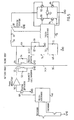
Figure 5 is a schematic view of exemplary circuitry used for the components of the block diagram ofFig. 4 . - Referring to the drawing figures, like reference numerals designate identical or corresponding elements throughout the several figures.
-
Figs. 1-3 show an example of a part of the food intake restriction device of the invention, comprising a circular resilientnon-inflatable restriction member 2 with two overlappingend portions 4,6. Therestriction member 2 defines a substantially circular restriction opening and is enclosed in an elasticsoft hose 8 except at a releasable and lockable joint 10 of therestriction member 2, which when released enables application of therestriction member 2 with itshose 8 around the esophagus or stomach of a patient in a surgical procedure. All of the in body components are desirably of bio-compatible material or covered with bio-compatible material. - An adjustment means 12 mechanically adjusts the longitudinal extension of the
restriction member 2 to change the size of said restriction opening. The adjustment means may comprise any known or conventional mechanical device for this purpose. The illustrated embodiment of thedevice 12 comprises apulley 14 in frictional engagement with the overlappingend portions 4,6. Thepulley 14 is journalled on aholder 16 placed in thehose 8 and provided with twocounter pressure rollers respective end portions 4, 6 against thepulley 14 to increase the frictional engagement therebetween. Anelectric motor 22 is connected to thepulley 14 via a longflexible drive shaft 24 and is moulded together with anenergizer unit 26 in abody 28 of silicone. The length of theflexible drive shaft 24 is selected so that thebody 28 can be placed in a desired position in the abdomen of the patient. All components are of bio-compatible material, or covered with bio-compatible material. - If the patient some time after the operation needs adjustment of the restriction opening of the
restriction member 2, theenergizer unit 26 is controlled to power theelectric motor 22 either to rotate thepulley 14 in one direction to reduce the diameter of thecircular restriction member 2 or to rotate thepulley 14 in the opposite direction to increase the diameter of therestriction member 2. - It should be understood that the implantable part of the device described above alternatively may be one of a variety of different adjustable designs. For example, the elongated restriction member may be inflatable by a fluid, which is pumped to and from the restriction member by a pump operated by the
motor 22. -
Fig. 4 shows the basic parts of an exemplary remote control system of the device of the invention including theelectric motor 22. This remote control system is based on the transmission of electromagnetic wave signals, often of high frequencies on the order of 100 kHz - 1 gHz, through theskin 30 of the patient. For the first embodiment of the invention any known or developed remote control system may be utilized; electromagnetic wave signals do not need to be transmitted. InFig. 4 , all parts placed to the left of theskin 30 are located outside the patient's body and are thus not implanted, whereas all parts placed to the right of theskin 30 are implanted. - An external
signal transmitting antenna 32 is to be positioned close to asignal receiving antenna 34 implanted close to theskin 30. As an alternative, the receivingantenna 34 may be placed, for example, inside the abdomen of the patient. The receivingantenna 34 may comprise a coil, approximately 1-100 mm, preferably 25 mm in diameter, wound with a very thin wire and tuned with a capacitor to a specific high frequency. A small coil is chosen if it is to be implanted under the skin of the patient and a large coil is chosen if it is to be implanted in the abdomen of the patient. The transmittingantenna 32 comprises a coil having about the same size as the coil of the receivingantenna 34 but wound with a thick wire that can handle the larger currents that is necessary. The coil of the transmittingantenna 32 is tuned to the same specific high frequency as the coil of the receivingantenna 34. - An
external control unit 36 preferably comprises a microprocessor, a high frequency electromagnetic wave signal generator and a power amplifier. The microprocessor of thecontrol unit 36 is adapted to switch the generator on/off and to modulate signals generated by the generator to send digital information via the power amplifier and theantennas control unit 38. To avoid accidental random high frequency fields triggering control commands, digital signal codes are used. A conventional keypad 37 placed on theexternal control unit 36 is connected to the microprocessor thereof. The keypad 37 is used to order the microprocessor to send digital signals to either increase or decrease the size of therestriction opening 3 defined by the loop of therestriction member 2. The microprocessor starts a command by applying a high frequency signal on theantenna 32. After a short time, when the signal has energized the implanted parts of the control system, commands are sent to increase or decrease the size of said restriction opening of therestriction member 2 in predefined steps. The commands are preferably sent as digital packets in the form illustrated below.Start pattern, Command, Count, Checksum, 8 bits 8 bits 8 bits 8 bits control unit 38 to decode and understand that another step is demanded by theexternal control unit 36. If any part of the digital packet is erroneous, its content is simply ignored. - Through a
line 40, the implantedenergizer unit 26 draws energy from the high frequency electromagnetic wave signals received by the receivingantenna 34. Theenergizer unit 26 stores the energy in a power supply, such as a large capacitor, powers thecontrol unit 38 and powers theelectric motor 22 via aline 42. - The
control unit 38 comprises a demodulator and a microprocessor. The demodulator demodulates digital signals sent from theexternal control unit 36. The microprocessor of thecontrol unit 38 receives the digital packet, decodes it and, provided that the power supply of theenergizer unit 26 has sufficient energy stored, sends a signal via asignal line 44 to themotor 22 to either increase or decrease the size of therestriction opening 3 of therestriction member 2 depending on the received command code. - With reference to
Fig. 5 , the remote control system schematically described above will now be described in accordance with a more detailed embodiment. Theexternal control unit 36 comprises a microprocessor 46, asignal generator 48 and apower amplifier 50 connected thereto. The microprocessor 46 switches thesignal generator 48 on/off and to modulate signals generated by thesignal generator 48 with digital commands that are sent to implanted components (to the right ofskin 30 inFig.5 ) of the implantable device. Thepower amplifier 50 amplifies the signals and sends them to the externalsignal transmitting antenna 32. Theantenna 32 is connected in parallel with acapacitor 52 to form a resonant circuit tuned to the frequency generated by thesignal generator 48. - The implanted signal receiving
antenna coil 34 forms together with a capacitor 54 a resonant circuit that is tuned to the same frequency as the transmittingantenna 32. The signal receivingantenna coil 34 induces a current from the received high frequency electromagnetic waves and a rectifyingdiode 60 rectifies the induced current, which charges astorage capacitor 58. Acoil 56 connected between theantenna coil 34 and thediode 60 prevents thecapacitor 58 and thediode 60 from loading the circuit of thesignal receiving antenna 34 at higher frequencies. Thus, thecoil 56 makes it possible to charge thecapacitor 58 and to transmit digital information using amplitude modulation. - A
capacitor 62 and aresistor 64 connected in parallel and adiode 66 forms a detector used to detect amplitude modulated digital information. A filter circuit is formed by aresistor 68 connected in series with a resistor 70, in turn connected in series with acapacitor 72, in turn connected in series with theresistor 68 via ground, and acapacitor 74, one terminal of which is connected between theresistors 68,70 and the other terminal of which is connected between thediode 66 and the circuit formed by thecapacitor 62 andresistor 64. The filter circuit is used to filter out undesired low and high frequencies. The detected and filtered signals are fed to an implanted microprocessor 76 that decodes the digital information and controls themotor 22 via an H-bridge 78 comprisingtransistors motor 22 can be driven in two opposite directions by the H-bridge 78. - The microprocessor 76 also monitors the amount of stored energy in the
storage capacitor 58. Before sending signals to activate themotor 22, the microprocessor 76 checks whether the energy stored in thestorage capacitor 58 is enough. If the stored energy is not enough to perform the requested operation, the microprocessor 76 waits for the received signals to charge thestorage capacitor 58 before activating themotor 22. - With the aid of the remote control means it is possible to programme various sizes of the restriction opening which are to be set by the adjustment means depending on the time of the day. For example, the restriction opening may be relatively large at night, which may be beneficial with respect to the patient's well-being. Means may also be provided for sensing the actual size of the restriction opening so that the adjustment means can be controlled by the remote control means to adjust the restriction opening in response to such a sensing means.
- There are a number of conceivable alternative embodiments of the invention that give the same result as the above-described embodiments. For example, the microprocessor of the external and implanted, respectively, control units may be replaced by discrete components. The power amplifier of the external control unit may be omitted if the signals generated by the signal generator are strong enough. Therefore, the invention is to be accorded the broadest interpretation of the appended claims to encompass all equivalent structures and assemblies.
- One further advantage with this invention is that there may be a night button on the remote control setting the adjustment means in a position with a larger stoma diameter during the night, thus avoiding vomiting or nausa.
Claims (13)
- A food intake restriction device for forming a stoma opening in the stomach or esophagus of a patient, the device comprising an elongated restriction member (2), forming means (10) for forming the elongated restriction member into at least a substantially closed loop around the patient's stomach or esophagus, said loop defining a restriction opening (3), and an implantable adjustment means (12) for adjusting the restriction member in said loop to change the size of said restriction opening, characterised by a wireless remote control means (22,26,32-44) for non-invasively controlling the adjustment means (12) to adjust the restriction member (2), to thereby obtain a desired size of said restriction opening, wherein:the remote control means (22,26,32-44) comprises means for wireless transfer of energy from outside the patient's body to all energy consuming implantable components of the device.
- The device according to claim 1, wherein the remote control means (22,26,32-44) comprises separate signal transmitting means (32,36) and implantable signal receiving means (34,38).
- The device according to claim 2, wherein the signal receiving means (34,38) comprises a control unit (38) adapted to control the adjustment means (12) in response to signals from the signal transmitting means (32,36).
- The device according to claim 3, further comprising an implantable energizer unit (26) for providing energy to energy consuming components of the device to be implanted in the patient.
- The device according to claim 4, further comprising an implantable motor (22) for operating the adjustment means (12).
- The device according to claim 5, wherein the control unit (38) is adapted to power the motor (22) with energy provided by the energizer unit (26) in response to signals received from the signal transmitting means (32,36).
- The device according to claim 6, wherein the energizer unit (26) comprises a power supply (58).
- The device according to claim 7, wherein the power supply (58) is an electric power supply and the motor (22) is an electric motor.
- The device according to claim 8, wherein the electric power supply comprises a battery.
- The device according to claim 1, further comprising an implantable motor (22) for operating the adjustment means (12), said means for wireless transfer of energy being adapted to directly power the motor with transferred energy.
- The device according to claim 10, wherein the energy transferred by said means for transfer of energy comprises wave signals.
- The device according to claim 10, wherein the energy transferred by said means for transfer of energy comprises an electric field or a magnetic field.
- The device according to claim 1, wherein the remote control means (22,26,32-44) is capable of obtaining information on the size of the restriction opening(3) and to command the adjustment means (12) to adjust the restriction member (2) in response to obtained information.
Priority Applications (1)
| Application Number | Priority Date | Filing Date | Title |
|---|---|---|---|
| EP10178703A EP2292191B1 (en) | 1998-08-13 | 1999-08-12 | Food intake restriction device |
Applications Claiming Priority (3)
| Application Number | Priority Date | Filing Date | Title |
|---|---|---|---|
| US09/133,319 US6210347B1 (en) | 1998-08-13 | 1998-08-13 | Remote control food intake restriction device |
| EP05075924A EP1554998B1 (en) | 1998-08-13 | 1999-08-12 | Medical device for restriction of food intake |
| EP99943571A EP1105074B1 (en) | 1998-08-13 | 1999-08-12 | Food intake restriction device |
Related Parent Applications (3)
| Application Number | Title | Priority Date | Filing Date |
|---|---|---|---|
| EP05075924A Division EP1554998B1 (en) | 1998-08-13 | 1999-08-12 | Medical device for restriction of food intake |
| EP99943571.2 Division | 1999-08-12 | ||
| EP05075924.0 Division | 2005-04-18 |
Related Child Applications (2)
| Application Number | Title | Priority Date | Filing Date |
|---|---|---|---|
| EP10178703A Division EP2292191B1 (en) | 1998-08-13 | 1999-08-12 | Food intake restriction device |
| EP10178703.4 Division-Into | 2010-09-23 |
Publications (2)
| Publication Number | Publication Date |
|---|---|
| EP2002809A1 EP2002809A1 (en) | 2008-12-17 |
| EP2002809B1 true EP2002809B1 (en) | 2011-04-13 |
Family
ID=22458026
Family Applications (4)
| Application Number | Title | Priority Date | Filing Date |
|---|---|---|---|
| EP99943571A Expired - Lifetime EP1105074B1 (en) | 1998-08-13 | 1999-08-12 | Food intake restriction device |
| EP10178703A Expired - Lifetime EP2292191B1 (en) | 1998-08-13 | 1999-08-12 | Food intake restriction device |
| EP08075768A Expired - Lifetime EP2002809B1 (en) | 1998-08-13 | 1999-08-12 | Food intake restriction device |
| EP05075924A Expired - Lifetime EP1554998B1 (en) | 1998-08-13 | 1999-08-12 | Medical device for restriction of food intake |
Family Applications Before (2)
| Application Number | Title | Priority Date | Filing Date |
|---|---|---|---|
| EP99943571A Expired - Lifetime EP1105074B1 (en) | 1998-08-13 | 1999-08-12 | Food intake restriction device |
| EP10178703A Expired - Lifetime EP2292191B1 (en) | 1998-08-13 | 1999-08-12 | Food intake restriction device |
Family Applications After (1)
| Application Number | Title | Priority Date | Filing Date |
|---|---|---|---|
| EP05075924A Expired - Lifetime EP1554998B1 (en) | 1998-08-13 | 1999-08-12 | Medical device for restriction of food intake |
Country Status (11)
| Country | Link |
|---|---|
| US (1) | US6210347B1 (en) |
| EP (4) | EP1105074B1 (en) |
| AT (3) | ATE457709T1 (en) |
| AU (1) | AU746182B2 (en) |
| BR (1) | BR9912793A (en) |
| CA (1) | CA2338360C (en) |
| DE (3) | DE69943362D1 (en) |
| DK (1) | DK1105074T3 (en) |
| ES (1) | ES2245116T3 (en) |
| MX (1) | MXPA01000599A (en) |
| WO (1) | WO2000009048A1 (en) |
Families Citing this family (225)
| Publication number | Priority date | Publication date | Assignee | Title |
|---|---|---|---|---|
| JP2002524124A (en) * | 1998-09-04 | 2002-08-06 | ウルフ リサーチ プロプライエタリー リミテッド | Medical implantation system |
| US20050192629A1 (en) * | 1999-06-25 | 2005-09-01 | Usgi Medical Inc. | Methods and apparatus for creating and regulating a gastric stoma |
| EP1072282A1 (en) * | 1999-07-19 | 2001-01-31 | EndoArt S.A. | Flow control device |
| FR2797181B1 (en) * | 1999-08-05 | 2002-05-03 | Richard Cancel | REMOTE GASTRIC BAND DEVICE FOR FORMING A RESTRICTED STOMA OPENING IN THE ESTOMAC |
| US6464628B1 (en) * | 1999-08-12 | 2002-10-15 | Obtech Medical Ag | Mechanical anal incontinence |
| US6482145B1 (en) | 2000-02-14 | 2002-11-19 | Obtech Medical Ag | Hydraulic anal incontinence treatment |
| US6454699B1 (en) * | 2000-02-11 | 2002-09-24 | Obtech Medical Ag | Food intake restriction with controlled wireless energy supply |
| AU772366B2 (en) * | 1999-08-12 | 2004-04-22 | Implantica Patent Ltd. | Medical implant apparatus with wireless energy transmission |
| CA2379441C (en) * | 1999-08-12 | 2009-11-24 | Potencia Medical Ag | Stoma opening forming apparatus |
| US6454701B1 (en) | 1999-08-12 | 2002-09-24 | Obtech Medical Ag | Heartburn and reflux disease treatment apparatus with energy transfer device |
| US6453907B1 (en) * | 1999-08-12 | 2002-09-24 | Obtech Medical Ag | Food intake restriction with energy transfer device |
| US6450173B1 (en) | 1999-08-12 | 2002-09-17 | Obtech Medical Ag | Heartburn and reflux disease treatment with controlled wireless energy supply |
| US6471635B1 (en) | 2000-02-10 | 2002-10-29 | Obtech Medical Ag | Anal incontinence disease treatment with controlled wireless energy supply |
| US6454698B1 (en) * | 1999-08-12 | 2002-09-24 | Obtech Medical Ag | Anal incontinence treatment with energy transfer device |
| US6454700B1 (en) * | 2000-02-09 | 2002-09-24 | Obtech Medical Ag | Heartburn and reflux disease treatment apparatus with wireless energy supply |
| EP1253879B1 (en) | 2000-02-10 | 2005-10-12 | Potencia Medical AG | Urinary incontinence treatment with wireless energy supply |
| EP1253877B1 (en) * | 2000-02-10 | 2005-05-11 | Potencia Medical AG | Mechanical impotence treatment apparatus |
| ATE410982T1 (en) * | 2000-02-10 | 2008-10-15 | Obtech Medical Ag | REGULATED DEVICE FOR THE TREATMENT OF HEARTBURN AND ACID REGULS |
| US6463935B1 (en) | 2000-02-10 | 2002-10-15 | Obtech Medical Ag | Controlled heartburn and reflux disease treatment |
| AU759363B2 (en) * | 2000-02-10 | 2003-04-10 | Implantica Patent Ltd. | Controlled urinary incontinence treatment |
| US6450946B1 (en) * | 2000-02-11 | 2002-09-17 | Obtech Medical Ag | Food intake restriction with wireless energy transfer |
| MXPA02007704A (en) * | 2000-02-11 | 2002-10-17 | Obtech Medical Ag | Food intake restriction apparatus with controlled wireless energy supply. |
| AU778406B2 (en) | 2000-02-11 | 2004-12-02 | Potentica Ag | Controlled impotence treatment |
| US20030125768A1 (en) * | 2000-02-11 | 2003-07-03 | Forsell Peter | Impotence treatment apparatus with energy transforming means |
| US20030100929A1 (en) | 2000-02-14 | 2003-05-29 | Peter Forsell | Controlled penile prosthesis |
| DE60111019T2 (en) | 2000-02-14 | 2006-05-11 | Potencia Medical Ag | PROSTHESIS |
| EP1255514B1 (en) * | 2000-02-14 | 2006-04-26 | Potencia Medical AG | Male impotence prosthesis apparatus with wireless energy supply |
| US6475136B1 (en) | 2000-02-14 | 2002-11-05 | Obtech Medical Ag | Hydraulic heartburn and reflux treatment |
| US6527701B1 (en) * | 2000-09-29 | 2003-03-04 | Precision Medical Devices, Inc. | Body fluid flow control device |
| US7011621B2 (en) * | 2000-09-29 | 2006-03-14 | Precision Medical Devices, Inc. | Body fluid flow control method and device |
| US9655705B1 (en) * | 2000-09-29 | 2017-05-23 | Precision Medical Devices, Inc. | Body canal contacting means for body fluid flow control methods and devices |
| FR2816828B1 (en) * | 2000-11-23 | 2004-10-22 | Richard Cancel | DEVICE FOR THE REMOTE IMPLEMENTATION AND WITHOUT A MATERIAL LINK OF AN IMPLANT AND IMPLANT IMPLEMENTED BY THIS DEVICE |
| US6551235B2 (en) * | 2001-06-28 | 2003-04-22 | Potencia Medical Ag | Implantable pump |
| WO2003075256A1 (en) * | 2002-03-05 | 2003-09-12 | Nec Corporation | Image display and its control method |
| US20040034275A1 (en) * | 2002-07-29 | 2004-02-19 | Peter Forsell | Multi-material incontinence treatment constriction device |
| EP1539262A1 (en) * | 2002-07-29 | 2005-06-15 | Potencia Medical AG | Durable implant |
| WO2004014245A1 (en) * | 2002-08-13 | 2004-02-19 | Inamed Medical Products Corporation | Remotely adjustable gastric banding device and method |
| US7338433B2 (en) * | 2002-08-13 | 2008-03-04 | Allergan, Inc. | Remotely adjustable gastric banding method |
| ES2339009T3 (en) | 2002-08-28 | 2010-05-14 | Allergan, Inc. | FATIGUE RESISTANT GASTRIC BAND DEVICE. |
| US20040220516A1 (en) * | 2002-11-04 | 2004-11-04 | Stephen Solomon | Food extraction apparatus and method |
| US9055995B2 (en) * | 2002-11-04 | 2015-06-16 | Aspire Bariatrics, Inc. | Method for treating obesity by extracting food |
| US7740624B2 (en) * | 2002-11-04 | 2010-06-22 | Aspiration Medical Technology, Llc | Method for treating obesity by extracting food |
| US7815629B2 (en) * | 2002-11-04 | 2010-10-19 | Deka Products Limited Partnership | Apparatus for treating obesity by extracting food |
| EP1587463B8 (en) * | 2003-01-31 | 2007-04-25 | Oblicus AG | Electrically operable incontinence treatment apparatus |
| EP1587455B8 (en) * | 2003-01-31 | 2007-05-02 | Instant Communication AG | Electrically operable impotence treatment apparatus |
| MXPA06003005A (en) * | 2003-09-15 | 2006-06-23 | Inamed Medical Products Corp | Implantable device fastening system and methods of use. |
| US20050080444A1 (en) * | 2003-10-14 | 2005-04-14 | Kraemer Stefan J.M. | Transesophageal gastric reduction device, system and method |
| PL1670362T3 (en) * | 2004-01-23 | 2011-05-31 | Apollo Endosurgery Inc | Implantable device fastening system and methods of use |
| ES2399951T3 (en) | 2004-01-23 | 2013-04-04 | Allergan, Inc. | Adjustable gastric band of a piece that can be fixed releasably |
| DE602005016901D1 (en) * | 2004-03-08 | 2009-11-12 | Allergan Medical S A | CLOSING SYSTEM FOR TUBULAR ORGANS |
| EP1732635B1 (en) * | 2004-03-18 | 2011-07-27 | Allergan, Inc. | Apparatus for volume adjustment of intragastric balloons |
| US7803195B2 (en) * | 2004-06-03 | 2010-09-28 | Mayo Foundation For Medical Education And Research | Obesity treatment and device |
| US20050288777A1 (en) * | 2004-06-29 | 2005-12-29 | Rhee Richard S | Thermal conductor for adjustable cardiac valve implant |
| US7955357B2 (en) | 2004-07-02 | 2011-06-07 | Ellipse Technologies, Inc. | Expandable rod system to treat scoliosis and method of using the same |
| US20060020277A1 (en) * | 2004-07-20 | 2006-01-26 | Gostout Christopher J | Gastric reshaping devices and methods |
| US7601162B2 (en) * | 2005-01-14 | 2009-10-13 | Ethicon Endo-Surgery, Inc. | Actuator for an implantable band |
| US7879068B2 (en) * | 2005-01-14 | 2011-02-01 | Ethicon Endo-Surgery, Inc. | Feedback sensing for a mechanical restrictive device |
| US7775966B2 (en) * | 2005-02-24 | 2010-08-17 | Ethicon Endo-Surgery, Inc. | Non-invasive pressure measurement in a fluid adjustable restrictive device |
| US20060173472A1 (en) * | 2005-01-31 | 2006-08-03 | Starkebaum Warren L | Gastric banding device |
| US20060173238A1 (en) * | 2005-01-31 | 2006-08-03 | Starkebaum Warren L | Dynamically controlled gastric occlusion device |
| US20060252983A1 (en) * | 2005-02-11 | 2006-11-09 | Lembo Nicholas J | Dynamically adjustable gastric implants and methods of treating obesity using dynamically adjustable gastric implants |
| US8066629B2 (en) | 2005-02-24 | 2011-11-29 | Ethicon Endo-Surgery, Inc. | Apparatus for adjustment and sensing of gastric band pressure |
| US7927270B2 (en) | 2005-02-24 | 2011-04-19 | Ethicon Endo-Surgery, Inc. | External mechanical pressure sensor for gastric band pressure measurements |
| US8016744B2 (en) | 2005-02-24 | 2011-09-13 | Ethicon Endo-Surgery, Inc. | External pressure-based gastric band adjustment system and method |
| US7699770B2 (en) | 2005-02-24 | 2010-04-20 | Ethicon Endo-Surgery, Inc. | Device for non-invasive measurement of fluid pressure in an adjustable restriction device |
| US7775215B2 (en) * | 2005-02-24 | 2010-08-17 | Ethicon Endo-Surgery, Inc. | System and method for determining implanted device positioning and obtaining pressure data |
| US7909754B2 (en) * | 2005-02-24 | 2011-03-22 | Ethicon Endo-Surgery, Inc. | Non-invasive measurement of fluid pressure in an adjustable gastric band |
| US7658196B2 (en) | 2005-02-24 | 2010-02-09 | Ethicon Endo-Surgery, Inc. | System and method for determining implanted device orientation |
| US8608797B2 (en) | 2005-03-17 | 2013-12-17 | Valtech Cardio Ltd. | Mitral valve treatment techniques |
| WO2006107901A1 (en) * | 2005-04-04 | 2006-10-12 | Micardia Corporation | Dynamic reinforcement of the lower esophageal sphincter |
| US8251888B2 (en) | 2005-04-13 | 2012-08-28 | Mitchell Steven Roslin | Artificial gastric valve |
| US20060244291A1 (en) * | 2005-04-29 | 2006-11-02 | Buell Motorcycle Company | Movable tailrack for a motorcycle |
| WO2006122019A2 (en) * | 2005-05-09 | 2006-11-16 | Wilson-Cook Medical, Inc. | Intragastric device for treating obesity |
| CA2611477C (en) | 2005-06-10 | 2012-01-17 | Wilson-Cook Medical, Inc. | Cautery catheter |
| US8951285B2 (en) | 2005-07-05 | 2015-02-10 | Mitralign, Inc. | Tissue anchor, anchoring system and methods of using the same |
| US8182411B2 (en) * | 2005-07-15 | 2012-05-22 | Ethicon Endo-Surgery, Inc. | Gastric band with mating end profiles |
| US7367937B2 (en) * | 2005-07-15 | 2008-05-06 | Ethicon Endo-Surgey, Inc. | Gastric band |
| US8298133B2 (en) * | 2005-07-15 | 2012-10-30 | Ethicon Endo-Surgery, Inc. | Gastric band composed of different hardness materials |
| US20070015955A1 (en) * | 2005-07-15 | 2007-01-18 | Mark Tsonton | Accordion-like gastric band |
| US7618365B2 (en) * | 2005-07-15 | 2009-11-17 | Ethicon Endo-Surgery, Inc. | Method of implating a medical device using a suture tab extender |
| US7364542B2 (en) * | 2005-07-15 | 2008-04-29 | Ethicon Endo-Surgery, Inc. | Gastric band suture tab extender |
| US7416528B2 (en) | 2005-07-15 | 2008-08-26 | Ethicon Endo-Surgery, Inc. | Latching device for gastric band |
| US7615001B2 (en) * | 2005-07-15 | 2009-11-10 | Ethicon Endo-Surgery, Inc. | Precurved gastric band |
| US7766815B2 (en) * | 2005-07-28 | 2010-08-03 | Ethicon Endo-Surgery, Inc. | Electroactive polymer actuated gastric band |
| JP5021675B2 (en) * | 2005-12-22 | 2012-09-12 | クック メディカル テクノロジーズ エルエルシー | Coil-like intragastric member for the treatment of obesity |
| US8216268B2 (en) * | 2005-12-22 | 2012-07-10 | Cook Medical Technologies Llc | Intragastric bag for treating obesity |
| US7798954B2 (en) * | 2006-01-04 | 2010-09-21 | Allergan, Inc. | Hydraulic gastric band with collapsible reservoir |
| US8043206B2 (en) * | 2006-01-04 | 2011-10-25 | Allergan, Inc. | Self-regulating gastric band with pressure data processing |
| US20070198039A1 (en) * | 2006-01-27 | 2007-08-23 | Wilson-Cook Medical, Inc. | Intragastric device for treating obesity |
| US7908700B2 (en) * | 2006-02-28 | 2011-03-22 | Dipippo Joe J | Self-cleaning hair brush |
| US8870742B2 (en) | 2006-04-06 | 2014-10-28 | Ethicon Endo-Surgery, Inc. | GUI for an implantable restriction device and a data logger |
| US8152710B2 (en) | 2006-04-06 | 2012-04-10 | Ethicon Endo-Surgery, Inc. | Physiological parameter analysis for an implantable restriction device and a data logger |
| US7763039B2 (en) * | 2006-06-09 | 2010-07-27 | Ethicon Endo-Surgery, Inc. | Articulating blunt dissector/gastric band application device |
| EP2037849A2 (en) * | 2006-07-05 | 2009-03-25 | Aspiration Medical Technology, LLC | Shunt apparatus for treating obesity by extracting food |
| US20110082442A1 (en) * | 2006-07-05 | 2011-04-07 | Solovay Kenneth S | Externally reinforced percutaneous gastrostomy tube with customizable smooth tube length |
| US8062285B2 (en) * | 2006-08-03 | 2011-11-22 | Aspire Bariatrics, Llc | Systems and methods for removing ingested material from a stomach |
| US8632513B2 (en) * | 2006-08-03 | 2014-01-21 | Aspire Bariatrics, Inc. | Systems and methods for removing ingested material from a stomach |
| US20080319435A1 (en) * | 2006-10-12 | 2008-12-25 | Boston Scientific Scimed, Inc. | Shape-changing tissue constrictor and methods of use |
| US8246533B2 (en) | 2006-10-20 | 2012-08-21 | Ellipse Technologies, Inc. | Implant system with resonant-driven actuator |
| US7862502B2 (en) | 2006-10-20 | 2011-01-04 | Ellipse Technologies, Inc. | Method and apparatus for adjusting a gastrointestinal restriction device |
| US11259924B2 (en) | 2006-12-05 | 2022-03-01 | Valtech Cardio Ltd. | Implantation of repair devices in the heart |
| US9974653B2 (en) | 2006-12-05 | 2018-05-22 | Valtech Cardio, Ltd. | Implantation of repair devices in the heart |
| WO2010004546A1 (en) | 2008-06-16 | 2010-01-14 | Valtech Cardio, Ltd. | Annuloplasty devices and methods of delivery therefor |
| US11660190B2 (en) | 2007-03-13 | 2023-05-30 | Edwards Lifesciences Corporation | Tissue anchors, systems and methods, and devices |
| CA2685251A1 (en) * | 2007-05-04 | 2008-11-13 | Arizona Board Of Regents For And On Behalf Of Arizona State University | Systems and methods for wireless transmission of biopotentials |
| WO2008139463A2 (en) | 2007-05-09 | 2008-11-20 | Metacure Ltd. | Analysis and regulation of food intake |
| US8007507B2 (en) * | 2007-05-10 | 2011-08-30 | Cook Medical Technologies Llc | Intragastric bag apparatus and method of delivery for treating obesity |
| WO2009005625A1 (en) * | 2007-07-03 | 2009-01-08 | Synecor, Llc | Satiation devices and methods for controlling obesity |
| WO2009048396A1 (en) * | 2007-10-11 | 2009-04-16 | Milux Holding Sa | Method for controlling food flow in vertical banded gastroplasty |
| WO2009048368A1 (en) * | 2007-10-11 | 2009-04-16 | Milux Holding Sa | Apparatus and method for controlling food flow through the stomach of a patient |
| WO2009048400A1 (en) * | 2007-10-11 | 2009-04-16 | Milux Holding Sa | Method for controlling flow in a bodily organ |
| WO2009048398A1 (en) * | 2007-10-11 | 2009-04-16 | Milux Holding Sa | Method for controlling flow in a stomach |
| US8992409B2 (en) * | 2007-10-11 | 2015-03-31 | Peter Forsell | Method for controlling flow in a bodily organ |
| EP2211768B1 (en) * | 2007-10-11 | 2021-03-24 | Implantica Patent Ltd. | Apparatus for controlling flow in a bodily organ |
| US8696543B2 (en) * | 2007-10-11 | 2014-04-15 | Kirk Promotion Ltd. | Method for controlling flow of intestinal contents in a patient's intestines |
| EP2211789B1 (en) * | 2007-10-11 | 2023-06-07 | Implantica Patent Ltd. | Apparatus and method for controlling food flow through a compartmentalized stomach of a patient |
| US8795153B2 (en) | 2007-10-11 | 2014-08-05 | Peter Forsell | Method for treating female sexual dysfunction |
| US20090112263A1 (en) | 2007-10-30 | 2009-04-30 | Scott Pool | Skeletal manipulation system |
| US20090149879A1 (en) * | 2007-12-10 | 2009-06-11 | Dillon Travis E | Dynamic volume displacement weight loss device |
| US7883524B2 (en) * | 2007-12-21 | 2011-02-08 | Wilson-Cook Medical Inc. | Method of delivering an intragastric device for treating obesity |
| US8016851B2 (en) * | 2007-12-27 | 2011-09-13 | Cook Medical Technologies Llc | Delivery system and method of delivery for treating obesity |
| EP2244662B1 (en) | 2008-01-28 | 2021-09-29 | Implantica Patent Ltd. | Blood clot removal device and system |
| AU2015205843B2 (en) * | 2008-01-29 | 2017-08-10 | Implantica Patent Ltd. | A device, system and method for treating obesity |
| WO2009096861A1 (en) * | 2008-01-29 | 2009-08-06 | Milux Holding Sa | Methods and instruments for treating obesity and gastroesophageal reflux disease |
| US8382829B1 (en) | 2008-03-10 | 2013-02-26 | Mitralign, Inc. | Method to reduce mitral regurgitation by cinching the commissure of the mitral valve |
| US11202707B2 (en) | 2008-03-25 | 2021-12-21 | Nuvasive Specialized Orthopedics, Inc. | Adjustable implant system |
| US20090248148A1 (en) | 2008-03-25 | 2009-10-01 | Ellipse Technologies, Inc. | Systems and methods for adjusting an annuloplasty ring with an integrated magnetic drive |
| ES2398974T3 (en) * | 2008-04-23 | 2013-03-25 | Allergan, Inc. | Remote gastric band application system |
| EP2320836B1 (en) * | 2008-06-11 | 2015-08-12 | Apollo Endosurgery, Inc. | Implantable pump system |
| ES2398948T3 (en) | 2008-07-14 | 2013-03-22 | Allergan, Inc. | Implantable pump system with calibration |
| US8105247B2 (en) | 2008-07-25 | 2012-01-31 | Buchwald O'dea Llc | Device for monitoring size of luminal cavity |
| US8317677B2 (en) | 2008-10-06 | 2012-11-27 | Allergan, Inc. | Mechanical gastric band with cushions |
| EP4282462A3 (en) | 2008-10-10 | 2024-02-21 | MedicalTree Patent Ltd. | Heart help device, system, and method |
| WO2010042058A1 (en) | 2008-10-10 | 2010-04-15 | Milux Holding S.A. | An improved artificial valve |
| US8874215B2 (en) | 2008-10-10 | 2014-10-28 | Peter Forsell | System, an apparatus, and a method for treating a sexual dysfunctional female patient |
| ES2962384T3 (en) | 2008-10-10 | 2024-03-18 | Implantica Patent Ltd | Device for the treatment of female sexual dysfunction |
| EP2349078A4 (en) | 2008-10-10 | 2018-02-07 | Kirk Promotion LTD. | Fastening means for implantable medcial control assembly |
| WO2010042019A1 (en) | 2008-10-10 | 2010-04-15 | Milux Holding Sa | Heart help device, system, and method |
| US20100185049A1 (en) | 2008-10-22 | 2010-07-22 | Allergan, Inc. | Dome and screw valves for remotely adjustable gastric banding systems |
| US8372093B2 (en) * | 2008-11-04 | 2013-02-12 | Koletry Processing L.L.C. | Systems and processes for controlling gastric bands based on geographic location |
| US8382756B2 (en) | 2008-11-10 | 2013-02-26 | Ellipse Technologies, Inc. | External adjustment device for distraction device |
| US8715342B2 (en) | 2009-05-07 | 2014-05-06 | Valtech Cardio, Ltd. | Annuloplasty ring with intra-ring anchoring |
| US8241351B2 (en) | 2008-12-22 | 2012-08-14 | Valtech Cardio, Ltd. | Adjustable partial annuloplasty ring and mechanism therefor |
| CN102341063B (en) | 2008-12-22 | 2015-11-25 | 瓦尔泰克卡迪欧有限公司 | Adjustable annuloplasty device and governor motion thereof |
| US9011530B2 (en) | 2008-12-22 | 2015-04-21 | Valtech Cardio, Ltd. | Partially-adjustable annuloplasty structure |
| US10517719B2 (en) | 2008-12-22 | 2019-12-31 | Valtech Cardio, Ltd. | Implantation of repair devices in the heart |
| US8545553B2 (en) | 2009-05-04 | 2013-10-01 | Valtech Cardio, Ltd. | Over-wire rotation tool |
| US8353956B2 (en) | 2009-02-17 | 2013-01-15 | Valtech Cardio, Ltd. | Actively-engageable movement-restriction mechanism for use with an annuloplasty structure |
| US8197490B2 (en) | 2009-02-23 | 2012-06-12 | Ellipse Technologies, Inc. | Non-invasive adjustable distraction system |
| US9622792B2 (en) | 2009-04-29 | 2017-04-18 | Nuvasive Specialized Orthopedics, Inc. | Interspinous process device and method |
| US20110184229A1 (en) * | 2009-05-01 | 2011-07-28 | Allergan, Inc. | Laparoscopic gastric band with active agents |
| US9968452B2 (en) | 2009-05-04 | 2018-05-15 | Valtech Cardio, Ltd. | Annuloplasty ring delivery cathethers |
| US9949812B2 (en) | 2009-07-17 | 2018-04-24 | Peter Forsell | Vaginal operation method for the treatment of anal incontinence in women |
| US10952836B2 (en) | 2009-07-17 | 2021-03-23 | Peter Forsell | Vaginal operation method for the treatment of urinary incontinence in women |
| US20110137112A1 (en) * | 2009-08-28 | 2011-06-09 | Allergan, Inc. | Gastric band with electric stimulation |
| US10098737B2 (en) | 2009-10-29 | 2018-10-16 | Valtech Cardio, Ltd. | Tissue anchor for annuloplasty device |
| US9180007B2 (en) | 2009-10-29 | 2015-11-10 | Valtech Cardio, Ltd. | Apparatus and method for guide-wire based advancement of an adjustable implant |
| EP2506777B1 (en) | 2009-12-02 | 2020-11-25 | Valtech Cardio, Ltd. | Combination of spool assembly coupled to a helical anchor and delivery tool for implantation thereof |
| US8678993B2 (en) * | 2010-02-12 | 2014-03-25 | Apollo Endosurgery, Inc. | Remotely adjustable gastric banding system |
| US20110201874A1 (en) * | 2010-02-12 | 2011-08-18 | Allergan, Inc. | Remotely adjustable gastric banding system |
| US8758221B2 (en) * | 2010-02-24 | 2014-06-24 | Apollo Endosurgery, Inc. | Source reservoir with potential energy for remotely adjustable gastric banding system |
| US8764624B2 (en) | 2010-02-25 | 2014-07-01 | Apollo Endosurgery, Inc. | Inductively powered remotely adjustable gastric banding system |
| US8840541B2 (en) | 2010-02-25 | 2014-09-23 | Apollo Endosurgery, Inc. | Pressure sensing gastric banding system |
| US8939888B2 (en) | 2010-04-28 | 2015-01-27 | Apollo Endosurgery, Inc. | Method and system for determining the pressure of a fluid in a syringe, an access port, a catheter, and a gastric band |
| US9028394B2 (en) | 2010-04-29 | 2015-05-12 | Apollo Endosurgery, Inc. | Self-adjusting mechanical gastric band |
| US9044298B2 (en) | 2010-04-29 | 2015-06-02 | Apollo Endosurgery, Inc. | Self-adjusting gastric band |
| US20110270024A1 (en) | 2010-04-29 | 2011-11-03 | Allergan, Inc. | Self-adjusting gastric band having various compliant components |
| US8594806B2 (en) | 2010-04-30 | 2013-11-26 | Cyberonics, Inc. | Recharging and communication lead for an implantable device |
| US20110270025A1 (en) | 2010-04-30 | 2011-11-03 | Allergan, Inc. | Remotely powered remotely adjustable gastric band system |
| US9226840B2 (en) * | 2010-06-03 | 2016-01-05 | Apollo Endosurgery, Inc. | Magnetically coupled implantable pump system and method |
| US8517915B2 (en) | 2010-06-10 | 2013-08-27 | Allergan, Inc. | Remotely adjustable gastric banding system |
| US9248043B2 (en) | 2010-06-30 | 2016-02-02 | Ellipse Technologies, Inc. | External adjustment device for distraction device |
| WO2012021378A2 (en) | 2010-08-09 | 2012-02-16 | Ellipse Technologies, Inc. | Maintenance feature in magnetic implant |
| US8698373B2 (en) | 2010-08-18 | 2014-04-15 | Apollo Endosurgery, Inc. | Pare piezo power with energy recovery |
| US9211207B2 (en) | 2010-08-18 | 2015-12-15 | Apollo Endosurgery, Inc. | Power regulated implant |
| US20120059216A1 (en) | 2010-09-07 | 2012-03-08 | Allergan, Inc. | Remotely adjustable gastric banding system |
| US8961393B2 (en) | 2010-11-15 | 2015-02-24 | Apollo Endosurgery, Inc. | Gastric band devices and drive systems |
| WO2012112396A2 (en) | 2011-02-14 | 2012-08-23 | Ellipse Technologies, Inc. | Device and method for treating fractured bones |
| US8725435B2 (en) | 2011-04-13 | 2014-05-13 | Apollo Endosurgery, Inc. | Syringe-based leak detection system |
| US10792152B2 (en) | 2011-06-23 | 2020-10-06 | Valtech Cardio, Ltd. | Closed band for percutaneous annuloplasty |
| US9918840B2 (en) | 2011-06-23 | 2018-03-20 | Valtech Cardio, Ltd. | Closed band for percutaneous annuloplasty |
| DE102011109378B4 (en) * | 2011-08-04 | 2017-06-22 | Fresenius Medical Care Deutschland Gmbh | Apparatus and method for securing a tubing segment to a device for monitoring patient access |
| US10743794B2 (en) | 2011-10-04 | 2020-08-18 | Nuvasive Specialized Orthopedics, Inc. | Devices and methods for non-invasive implant length sensing |
| US10016220B2 (en) | 2011-11-01 | 2018-07-10 | Nuvasive Specialized Orthopedics, Inc. | Adjustable magnetic devices and methods of using same |
| US8858623B2 (en) | 2011-11-04 | 2014-10-14 | Valtech Cardio, Ltd. | Implant having multiple rotational assemblies |
| EP3970627B1 (en) | 2011-11-08 | 2023-12-20 | Edwards Lifesciences Innovation (Israel) Ltd. | Controlled steering functionality for implant-delivery tool |
| US8876694B2 (en) | 2011-12-07 | 2014-11-04 | Apollo Endosurgery, Inc. | Tube connector with a guiding tip |
| US8961394B2 (en) | 2011-12-20 | 2015-02-24 | Apollo Endosurgery, Inc. | Self-sealing fluid joint for use with a gastric band |
| US9343923B2 (en) | 2012-08-23 | 2016-05-17 | Cyberonics, Inc. | Implantable medical device with backscatter signal based communication |
| US9935498B2 (en) | 2012-09-25 | 2018-04-03 | Cyberonics, Inc. | Communication efficiency with an implantable medical device using a circulator and a backscatter signal |
| EP2900150B1 (en) | 2012-09-29 | 2018-04-18 | Mitralign, Inc. | Plication lock delivery system |
| WO2014064695A2 (en) | 2012-10-23 | 2014-05-01 | Valtech Cardio, Ltd. | Percutaneous tissue anchor techniques |
| US9949828B2 (en) | 2012-10-23 | 2018-04-24 | Valtech Cardio, Ltd. | Controlled steering functionality for implant-delivery tool |
| CA2889769A1 (en) | 2012-10-29 | 2014-05-08 | Ellipse Technologies, Inc. | Adjustable devices for treating arthritis of the knee |
| US9730793B2 (en) | 2012-12-06 | 2017-08-15 | Valtech Cardio, Ltd. | Techniques for guide-wire based advancement of a tool |
| AU2014218794B2 (en) | 2013-02-23 | 2018-03-08 | Aspire Bariatrics, Inc. | Apparatus and method for draining material from a stomach |
| US9724084B2 (en) | 2013-02-26 | 2017-08-08 | Mitralign, Inc. | Devices and methods for percutaneous tricuspid valve repair |
| US10449333B2 (en) | 2013-03-14 | 2019-10-22 | Valtech Cardio, Ltd. | Guidewire feeder |
| EP2968847B1 (en) | 2013-03-15 | 2023-03-08 | Edwards Lifesciences Corporation | Translation catheter systems |
| US10070857B2 (en) | 2013-08-31 | 2018-09-11 | Mitralign, Inc. | Devices and methods for locating and implanting tissue anchors at mitral valve commissure |
| US10751094B2 (en) | 2013-10-10 | 2020-08-25 | Nuvasive Specialized Orthopedics, Inc. | Adjustable spinal implant |
| WO2015059699A2 (en) | 2013-10-23 | 2015-04-30 | Valtech Cardio, Ltd. | Anchor magazine |
| US9610162B2 (en) | 2013-12-26 | 2017-04-04 | Valtech Cardio, Ltd. | Implantation of flexible implant |
| WO2015134747A1 (en) | 2014-03-06 | 2015-09-11 | Mayo Foundation For Medical Education And Research | Apparatus and methods of inducing weight loss using blood flow control |
| CN111345867A (en) | 2014-04-28 | 2020-06-30 | 诺威适骨科专科公司 | Remote control device |
| EP3206629B1 (en) | 2014-10-14 | 2021-07-14 | Valtech Cardio, Ltd. | Apparatus for heart valve leaflet restraining |
| JP6847341B2 (en) | 2014-12-26 | 2021-03-24 | ニューベイシブ スペシャライズド オーソペディックス,インコーポレイテッド | Systems and methods for extension |
| US10238427B2 (en) | 2015-02-19 | 2019-03-26 | Nuvasive Specialized Orthopedics, Inc. | Systems and methods for vertebral adjustment |
| US20160256269A1 (en) | 2015-03-05 | 2016-09-08 | Mitralign, Inc. | Devices for treating paravalvular leakage and methods use thereof |
| CN114515173A (en) | 2015-04-30 | 2022-05-20 | 瓦尔泰克卡迪欧有限公司 | Valvuloplasty techniques |
| WO2017066774A1 (en) | 2015-10-16 | 2017-04-20 | Nuvasive Specialized Orthopedics, Inc. | Adjustable devices for treating arthritis of the knee |
| CN108601611B (en) | 2015-12-10 | 2021-11-02 | 诺威适骨科专科公司 | External adjustment device for a tensioning device |
| US10751182B2 (en) | 2015-12-30 | 2020-08-25 | Edwards Lifesciences Corporation | System and method for reshaping right heart |
| WO2017117370A2 (en) | 2015-12-30 | 2017-07-06 | Mitralign, Inc. | System and method for reducing tricuspid regurgitation |
| CN108882953B (en) | 2016-01-28 | 2021-09-03 | 诺威适骨科专科公司 | System for bone migration |
| US10702274B2 (en) | 2016-05-26 | 2020-07-07 | Edwards Lifesciences Corporation | Method and system for closing left atrial appendage |
| GB201611910D0 (en) | 2016-07-08 | 2016-08-24 | Valtech Cardio Ltd | Adjustable annuloplasty device with alternating peaks and troughs |
| US11045627B2 (en) | 2017-04-18 | 2021-06-29 | Edwards Lifesciences Corporation | Catheter system with linear actuation control mechanism |
| US10835221B2 (en) | 2017-11-02 | 2020-11-17 | Valtech Cardio, Ltd. | Implant-cinching devices and systems |
| US11135062B2 (en) | 2017-11-20 | 2021-10-05 | Valtech Cardio Ltd. | Cinching of dilated heart muscle |
| EP3716907B1 (en) | 2017-12-01 | 2023-06-07 | C. R. Bard, Inc. | Adjustable vascular graft for custom inner diameter reduction and related methods |
| WO2019145947A1 (en) | 2018-01-24 | 2019-08-01 | Valtech Cardio, Ltd. | Contraction of an annuloplasty structure |
| EP3743014B1 (en) | 2018-01-26 | 2023-07-19 | Edwards Lifesciences Innovation (Israel) Ltd. | Techniques for facilitating heart valve tethering and chord replacement |
| AU2019301967A1 (en) | 2018-07-12 | 2021-01-21 | Edwards Lifesciences Innovation (Israel) Ltd. | Annuloplasty systems and locking tools therefor |
| CR20210640A (en) | 2019-10-29 | 2022-05-30 | Valtech Cardio Ltd | Annuloplasty and tissue anchor technologies |
Family Cites Families (14)
| Publication number | Priority date | Publication date | Assignee | Title |
|---|---|---|---|---|
| SE344275B (en) * | 1966-02-10 | 1972-04-10 | R Gruenert | |
| US3750194A (en) * | 1971-03-16 | 1973-08-07 | Fairchild Industries | Apparatus and method for reversibly closing a natural or implanted body passage |
| IL67773A (en) | 1983-01-28 | 1985-02-28 | Antebi E | Tie for tying live tissue and an instrument for performing said tying operation |
| US4592339A (en) | 1985-06-12 | 1986-06-03 | Mentor Corporation | Gastric banding device |
| US4696288A (en) | 1985-08-14 | 1987-09-29 | Kuzmak Lubomyr I | Calibrating apparatus and method of using same for gastric banding surgery |
| US5074868A (en) | 1990-08-03 | 1991-12-24 | Inamed Development Company | Reversible stoma-adjustable gastric band |
| US5226429A (en) | 1991-06-20 | 1993-07-13 | Inamed Development Co. | Laparoscopic gastric band and method |
| ATE173909T1 (en) | 1993-02-18 | 1998-12-15 | Lubomyr Ihor Kuzmak | LAPAROSCOPIC ADJUSTABLE GASTRIC BAND |
| US5601604A (en) | 1993-05-27 | 1997-02-11 | Inamed Development Co. | Universal gastric band |
| ES2132682T3 (en) * | 1994-07-11 | 1999-08-16 | Dacomed Corp | APPARATUS FOR OCCLUDING GLASSES. |
| US5509888A (en) * | 1994-07-26 | 1996-04-23 | Conceptek Corporation | Controller valve device and method |
| US5771903A (en) | 1995-09-22 | 1998-06-30 | Kirk Promotions Limited | Surgical method for reducing the food intake of a patient |
| FR2756485A1 (en) * | 1996-11-29 | 1998-06-05 | Cusset Claude | PROSTHETIC URINARY SPHINCTER WITH EXTERNAL CONTROL |
| US5938669A (en) * | 1997-05-07 | 1999-08-17 | Klasamed S.A. | Adjustable gastric banding device for contracting a patient's stomach |
-
1998
- 1998-08-13 US US09/133,319 patent/US6210347B1/en not_active Expired - Lifetime
-
1999
- 1999-08-12 CA CA002338360A patent/CA2338360C/en not_active Expired - Lifetime
- 1999-08-12 BR BR9912793-8A patent/BR9912793A/en not_active IP Right Cessation
- 1999-08-12 EP EP99943571A patent/EP1105074B1/en not_active Expired - Lifetime
- 1999-08-12 EP EP10178703A patent/EP2292191B1/en not_active Expired - Lifetime
- 1999-08-12 DK DK99943571T patent/DK1105074T3/en active
- 1999-08-12 DE DE69943362T patent/DE69943362D1/en not_active Expired - Lifetime
- 1999-08-12 AT AT05075924T patent/ATE457709T1/en not_active IP Right Cessation
- 1999-08-12 EP EP08075768A patent/EP2002809B1/en not_active Expired - Lifetime
- 1999-08-12 MX MXPA01000599A patent/MXPA01000599A/en active IP Right Grant
- 1999-08-12 DE DE69926132T patent/DE69926132T2/en not_active Expired - Lifetime
- 1999-08-12 WO PCT/SE1999/001366 patent/WO2000009048A1/en active IP Right Grant
- 1999-08-12 AU AU56640/99A patent/AU746182B2/en not_active Expired
- 1999-08-12 AT AT99943571T patent/ATE299362T1/en active
- 1999-08-12 AT AT08075768T patent/ATE505161T1/en not_active IP Right Cessation
- 1999-08-12 EP EP05075924A patent/EP1554998B1/en not_active Expired - Lifetime
- 1999-08-12 DE DE69942045T patent/DE69942045D1/en not_active Expired - Lifetime
- 1999-08-12 ES ES99943571T patent/ES2245116T3/en not_active Expired - Lifetime
Also Published As
| Publication number | Publication date |
|---|---|
| EP1105074B1 (en) | 2005-07-13 |
| EP1105074A1 (en) | 2001-06-13 |
| EP2002809A1 (en) | 2008-12-17 |
| DE69926132D1 (en) | 2005-08-18 |
| MXPA01000599A (en) | 2003-06-06 |
| DE69943362D1 (en) | 2011-05-26 |
| BR9912793A (en) | 2001-05-02 |
| EP1554998B1 (en) | 2010-02-17 |
| EP1554998A1 (en) | 2005-07-20 |
| DE69926132T2 (en) | 2006-05-11 |
| ES2245116T3 (en) | 2005-12-16 |
| CA2338360C (en) | 2009-11-24 |
| ATE299362T1 (en) | 2005-07-15 |
| US6210347B1 (en) | 2001-04-03 |
| DK1105074T3 (en) | 2005-10-31 |
| EP2292191A1 (en) | 2011-03-09 |
| DE69942045D1 (en) | 2010-04-01 |
| AU746182B2 (en) | 2002-04-18 |
| ATE457709T1 (en) | 2010-03-15 |
| EP2292191B1 (en) | 2012-09-19 |
| AU5664099A (en) | 2000-03-06 |
| CA2338360A1 (en) | 2000-02-24 |
| ATE505161T1 (en) | 2011-04-15 |
| WO2000009048A1 (en) | 2000-02-24 |
Similar Documents
| Publication | Publication Date | Title |
|---|---|---|
| EP2002809B1 (en) | Food intake restriction device | |
| EP1554997B1 (en) | Food intake restriction device | |
| AU775540B2 (en) | Food intake restriction apparatus with controlled wireless energy supply | |
| US6461293B1 (en) | Controlled food intake restriction | |
| US7017583B2 (en) | Food intake restriction with controlled wireless energy supply | |
| EP1554996B1 (en) | Food intake restriction device | |
| EP1609440B1 (en) | Anal incontinence treatment apparatus with controlled energy supply | |
| US7400926B2 (en) | Intestine dysfunction treatment apparatus | |
| US7648455B2 (en) | Controlled urinary incontinence treatment | |
| US6475136B1 (en) | Hydraulic heartburn and reflux treatment | |
| AU2004202000B2 (en) | Food intake restriction apparatus with controlled wireless energy supply | |
| AU2004205149A1 (en) | Anal incontinence treatment with controlled wireless energy supply |
Legal Events
| Date | Code | Title | Description |
|---|---|---|---|
| PUAI | Public reference made under article 153(3) epc to a published international application that has entered the european phase |
Free format text: ORIGINAL CODE: 0009012 |
|
| AC | Divisional application: reference to earlier application |
Ref document number: 1105074 Country of ref document: EP Kind code of ref document: P Ref document number: 1554998 Country of ref document: EP Kind code of ref document: P |
|
| AK | Designated contracting states |
Kind code of ref document: A1 Designated state(s): AT BE CH CY DE DK ES FI FR GB GR IE IT LI LU MC NL PT SE |
|
| 17P | Request for examination filed |
Effective date: 20090615 |
|
| AKX | Designation fees paid |
Designated state(s): AT BE CH CY DE DK ES FI FR GB GR IE IT LI LU MC NL PT SE |
|
| 17Q | First examination report despatched |
Effective date: 20090805 |
|
| GRAP | Despatch of communication of intention to grant a patent |
Free format text: ORIGINAL CODE: EPIDOSNIGR1 |
|
| GRAS | Grant fee paid |
Free format text: ORIGINAL CODE: EPIDOSNIGR3 |
|
| GRAA | (expected) grant |
Free format text: ORIGINAL CODE: 0009210 |
|
| AC | Divisional application: reference to earlier application |
Ref document number: 1105074 Country of ref document: EP Kind code of ref document: P Ref document number: 1554998 Country of ref document: EP Kind code of ref document: P |
|
| AK | Designated contracting states |
Kind code of ref document: B1 Designated state(s): AT BE CH CY DE DK ES FI FR GB GR IE IT LI LU MC NL PT SE |
|
| REG | Reference to a national code |
Ref country code: GB Ref legal event code: FG4D |
|
| REG | Reference to a national code |
Ref country code: CH Ref legal event code: EP |
|
| REG | Reference to a national code |
Ref country code: IE Ref legal event code: FG4D |
|
| REF | Corresponds to: |
Ref document number: 69943362 Country of ref document: DE Date of ref document: 20110526 Kind code of ref document: P |
|
| REG | Reference to a national code |
Ref country code: DE Ref legal event code: R096 Ref document number: 69943362 Country of ref document: DE Effective date: 20110526 |
|
| REG | Reference to a national code |
Ref country code: CH Ref legal event code: NV Representative=s name: E. BLUM & CO. AG PATENT- UND MARKENANWAELTE VSP |
|
| REG | Reference to a national code |
Ref country code: NL Ref legal event code: VDEP Effective date: 20110413 |
|
| REG | Reference to a national code |
Ref country code: SE Ref legal event code: TRGR |
|
| PG25 | Lapsed in a contracting state [announced via postgrant information from national office to epo] |
Ref country code: PT Free format text: LAPSE BECAUSE OF FAILURE TO SUBMIT A TRANSLATION OF THE DESCRIPTION OR TO PAY THE FEE WITHIN THE PRESCRIBED TIME-LIMIT Effective date: 20110816 |
|
| PG25 | Lapsed in a contracting state [announced via postgrant information from national office to epo] |
Ref country code: ES Free format text: LAPSE BECAUSE OF FAILURE TO SUBMIT A TRANSLATION OF THE DESCRIPTION OR TO PAY THE FEE WITHIN THE PRESCRIBED TIME-LIMIT Effective date: 20110724 Ref country code: GR Free format text: LAPSE BECAUSE OF FAILURE TO SUBMIT A TRANSLATION OF THE DESCRIPTION OR TO PAY THE FEE WITHIN THE PRESCRIBED TIME-LIMIT Effective date: 20110714 Ref country code: CY Free format text: LAPSE BECAUSE OF FAILURE TO SUBMIT A TRANSLATION OF THE DESCRIPTION OR TO PAY THE FEE WITHIN THE PRESCRIBED TIME-LIMIT Effective date: 20110413 Ref country code: AT Free format text: LAPSE BECAUSE OF FAILURE TO SUBMIT A TRANSLATION OF THE DESCRIPTION OR TO PAY THE FEE WITHIN THE PRESCRIBED TIME-LIMIT Effective date: 20110413 Ref country code: FI Free format text: LAPSE BECAUSE OF FAILURE TO SUBMIT A TRANSLATION OF THE DESCRIPTION OR TO PAY THE FEE WITHIN THE PRESCRIBED TIME-LIMIT Effective date: 20110413 |
|
| PG25 | Lapsed in a contracting state [announced via postgrant information from national office to epo] |
Ref country code: NL Free format text: LAPSE BECAUSE OF FAILURE TO SUBMIT A TRANSLATION OF THE DESCRIPTION OR TO PAY THE FEE WITHIN THE PRESCRIBED TIME-LIMIT Effective date: 20110413 |
|
| PLBE | No opposition filed within time limit |
Free format text: ORIGINAL CODE: 0009261 |
|
| STAA | Information on the status of an ep patent application or granted ep patent |
Free format text: STATUS: NO OPPOSITION FILED WITHIN TIME LIMIT |
|
| PG25 | Lapsed in a contracting state [announced via postgrant information from national office to epo] |
Ref country code: DK Free format text: LAPSE BECAUSE OF FAILURE TO SUBMIT A TRANSLATION OF THE DESCRIPTION OR TO PAY THE FEE WITHIN THE PRESCRIBED TIME-LIMIT Effective date: 20110413 |
|
| 26N | No opposition filed |
Effective date: 20120116 |
|
| PG25 | Lapsed in a contracting state [announced via postgrant information from national office to epo] |
Ref country code: MC Free format text: LAPSE BECAUSE OF NON-PAYMENT OF DUE FEES Effective date: 20110831 |
|
| REG | Reference to a national code |
Ref country code: DE Ref legal event code: R097 Ref document number: 69943362 Country of ref document: DE Effective date: 20120116 |
|
| REG | Reference to a national code |
Ref country code: IE Ref legal event code: MM4A |
|
| PG25 | Lapsed in a contracting state [announced via postgrant information from national office to epo] |
Ref country code: IE Free format text: LAPSE BECAUSE OF NON-PAYMENT OF DUE FEES Effective date: 20110812 |
|
| PG25 | Lapsed in a contracting state [announced via postgrant information from national office to epo] |
Ref country code: LU Free format text: LAPSE BECAUSE OF NON-PAYMENT OF DUE FEES Effective date: 20110812 |
|
| REG | Reference to a national code |
Ref country code: FR Ref legal event code: PLFP Year of fee payment: 18 |
|
| REG | Reference to a national code |
Ref country code: FR Ref legal event code: PLFP Year of fee payment: 19 |
|
| REG | Reference to a national code |
Ref country code: FR Ref legal event code: PLFP Year of fee payment: 20 |
|
| PGFP | Annual fee paid to national office [announced via postgrant information from national office to epo] |
Ref country code: DE Payment date: 20180731 Year of fee payment: 20 Ref country code: FR Payment date: 20180712 Year of fee payment: 20 Ref country code: IT Payment date: 20180823 Year of fee payment: 20 |
|
| PGFP | Annual fee paid to national office [announced via postgrant information from national office to epo] |
Ref country code: BE Payment date: 20180717 Year of fee payment: 20 Ref country code: CH Payment date: 20180817 Year of fee payment: 20 Ref country code: GB Payment date: 20180808 Year of fee payment: 20 Ref country code: SE Payment date: 20180810 Year of fee payment: 20 |
|
| REG | Reference to a national code |
Ref country code: DE Ref legal event code: R071 Ref document number: 69943362 Country of ref document: DE |
|
| REG | Reference to a national code |
Ref country code: CH Ref legal event code: PL |
|
| REG | Reference to a national code |
Ref country code: GB Ref legal event code: PE20 Expiry date: 20190811 |
|
| REG | Reference to a national code |
Ref country code: SE Ref legal event code: EUG |
|
| REG | Reference to a national code |
Ref country code: BE Ref legal event code: MK Effective date: 20190812 |
|
| PG25 | Lapsed in a contracting state [announced via postgrant information from national office to epo] |
Ref country code: GB Free format text: LAPSE BECAUSE OF EXPIRATION OF PROTECTION Effective date: 20190811 |