EP2002784A1 - Intravital-information imaging apparatus - Google Patents
Intravital-information imaging apparatus Download PDFInfo
- Publication number
- EP2002784A1 EP2002784A1 EP08157078A EP08157078A EP2002784A1 EP 2002784 A1 EP2002784 A1 EP 2002784A1 EP 08157078 A EP08157078 A EP 08157078A EP 08157078 A EP08157078 A EP 08157078A EP 2002784 A1 EP2002784 A1 EP 2002784A1
- Authority
- EP
- European Patent Office
- Prior art keywords
- light
- living body
- intravital
- distribution
- imaging apparatus
- Prior art date
- Legal status (The legal status is an assumption and is not a legal conclusion. Google has not performed a legal analysis and makes no representation as to the accuracy of the status listed.)
- Granted
Links
- 238000003384 imaging method Methods 0.000 title claims abstract description 27
- 239000006096 absorbing agent Substances 0.000 claims abstract description 61
- 230000003287 optical effect Effects 0.000 claims abstract description 30
- 230000001678 irradiating effect Effects 0.000 claims abstract description 5
- 238000000034 method Methods 0.000 claims description 13
- 230000008859 change Effects 0.000 claims description 12
- 238000010521 absorption reaction Methods 0.000 description 31
- 238000005259 measurement Methods 0.000 description 12
- 239000000470 constituent Substances 0.000 description 8
- 238000003325 tomography Methods 0.000 description 7
- 238000010586 diagram Methods 0.000 description 5
- 230000004044 response Effects 0.000 description 4
- 230000000694 effects Effects 0.000 description 3
- 206010028980 Neoplasm Diseases 0.000 description 2
- 210000004204 blood vessel Anatomy 0.000 description 2
- MOFVSTNWEDAEEK-UHFFFAOYSA-M indocyanine green Chemical compound [Na+].[O-]S(=O)(=O)CCCCN1C2=CC=C3C=CC=CC3=C2C(C)(C)C1=CC=CC=CC=CC1=[N+](CCCCS([O-])(=O)=O)C2=CC=C(C=CC=C3)C3=C2C1(C)C MOFVSTNWEDAEEK-UHFFFAOYSA-M 0.000 description 2
- 229960004657 indocyanine green Drugs 0.000 description 2
- 230000031700 light absorption Effects 0.000 description 2
- 239000000463 material Substances 0.000 description 2
- 239000003068 molecular probe Substances 0.000 description 2
- 238000012634 optical imaging Methods 0.000 description 2
- 230000000644 propagated effect Effects 0.000 description 2
- 230000002123 temporal effect Effects 0.000 description 2
- 102000008186 Collagen Human genes 0.000 description 1
- 108010035532 Collagen Proteins 0.000 description 1
- WQZGKKKJIJFFOK-GASJEMHNSA-N Glucose Natural products OC[C@H]1OC(O)[C@H](O)[C@@H](O)[C@@H]1O WQZGKKKJIJFFOK-GASJEMHNSA-N 0.000 description 1
- 102000001554 Hemoglobins Human genes 0.000 description 1
- 108010054147 Hemoglobins Proteins 0.000 description 1
- 230000009286 beneficial effect Effects 0.000 description 1
- 230000000903 blocking effect Effects 0.000 description 1
- 239000003795 chemical substances by application Substances 0.000 description 1
- 229920001436 collagen Polymers 0.000 description 1
- 238000009792 diffusion process Methods 0.000 description 1
- 239000008103 glucose Substances 0.000 description 1
- 238000002595 magnetic resonance imaging Methods 0.000 description 1
- 238000012986 modification Methods 0.000 description 1
- 230000004048 modification Effects 0.000 description 1
- 239000013307 optical fiber Substances 0.000 description 1
- 230000010355 oscillation Effects 0.000 description 1
- 238000011160 research Methods 0.000 description 1
- 238000012552 review Methods 0.000 description 1
- 239000004065 semiconductor Substances 0.000 description 1
- 230000007480 spreading Effects 0.000 description 1
- 238000012285 ultrasound imaging Methods 0.000 description 1
- 230000000007 visual effect Effects 0.000 description 1
Images



Classifications
-
- A—HUMAN NECESSITIES
- A61—MEDICAL OR VETERINARY SCIENCE; HYGIENE
- A61B—DIAGNOSIS; SURGERY; IDENTIFICATION
- A61B5/00—Measuring for diagnostic purposes; Identification of persons
- A61B5/0059—Measuring for diagnostic purposes; Identification of persons using light, e.g. diagnosis by transillumination, diascopy, fluorescence
-
- A—HUMAN NECESSITIES
- A61—MEDICAL OR VETERINARY SCIENCE; HYGIENE
- A61B—DIAGNOSIS; SURGERY; IDENTIFICATION
- A61B5/00—Measuring for diagnostic purposes; Identification of persons
- A61B5/0093—Detecting, measuring or recording by applying one single type of energy and measuring its conversion into another type of energy
- A61B5/0095—Detecting, measuring or recording by applying one single type of energy and measuring its conversion into another type of energy by applying light and detecting acoustic waves, i.e. photoacoustic measurements
-
- A—HUMAN NECESSITIES
- A61—MEDICAL OR VETERINARY SCIENCE; HYGIENE
- A61B—DIAGNOSIS; SURGERY; IDENTIFICATION
- A61B8/00—Diagnosis using ultrasonic, sonic or infrasonic waves
- A61B8/08—Clinical applications
-
- G—PHYSICS
- G01—MEASURING; TESTING
- G01N—INVESTIGATING OR ANALYSING MATERIALS BY DETERMINING THEIR CHEMICAL OR PHYSICAL PROPERTIES
- G01N21/00—Investigating or analysing materials by the use of optical means, i.e. using sub-millimetre waves, infrared, visible or ultraviolet light
- G01N21/17—Systems in which incident light is modified in accordance with the properties of the material investigated
- G01N21/1702—Systems in which incident light is modified in accordance with the properties of the material investigated with opto-acoustic detection, e.g. for gases or analysing solids
Definitions
- the present invention relates to intravital-information imaging apparatuses.
- imaging apparatuses that employ X-rays, ultrasound, or magnetic resonance imaging (MRI) are used in the medical field.
- MRI magnetic resonance imaging
- optical imaging apparatuses for obtaining intravital information by irradiating a living body with light from a light source, such as a laser, so that the light propagates in the living body, and detecting the propagated light or the like.
- Photoacoustic tomography As a type of optical imaging technique, photoacoustic tomography (PAT) has been proposed. Photoacoustic tomography is described, for example, in M. Xu and L. V. Wang, “Photoacoustic imaging in biomedicine”, Review of Scientific Instruments, 77, 041101 (2006 ).
- a living body In photoacoustic tomography, a living body is irradiated with pulsed light emitted from a light source, an acoustic wave generated from a biological tissue having absorbed the energy of light propagated and diffused in the living body is detected at multiple points, and corresponding signals are analyzed to form a visual image representing intravital information.
- This makes it possible to obtain a distribution of optical characteristic values in the living body, particularly, a distribution of optical-energy absorption densities.
- ⁇ denotes the Grüneisen coefficient, which is a value of elasticity characteristic determined by dividing the product of the thermal coefficient of volume expansion or isobaric volume expansion coefficient ( ⁇ ) and the square of the speed of light (c) by the specific heat at constant pressure (C p ).
- ⁇ a denotes the absorption coefficient of the light absorber, and ⁇ denotes the amount of local light indicating the optical fluence (light with which the light absorber is irradiated).
- the distribution of the products of ⁇ a and ⁇ i.e., the distribution of optical-energy absorption densities, can be obtained by measuring change in sound pressure P representing the magnitude of the acoustic wave at multiple points by time division.
- the present invention provides an intravital-information imaging apparatus with which it is possible to obtain a high-resolution distribution of optical characteristic values in a living body, particularly a distribution of optical absorption coefficients, or an average effective attenuation coefficient of a living body.
- the present invention provides an intravital-information imaging apparatus as specified in claims 1 to 7.
- the intravital-information imaging apparatus With the intravital-information imaging apparatus according to the present invention, it is possible to obtain a high-resolution distribution of optical characteristic values in a living body, particularly a distribution of optical absorption coefficients, or an average effective attenuation coefficient of a living body, and to generate images accurately representing such information.
- Figs. 1A and 1B are diagrams showing an example of the configuration of an intravital-information imaging apparatus according to a first embodiment of the present invention.
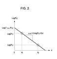
- Fig. 2 is a diagram showing an example of the result of analyzing signals obtained by the intravital-information imaging apparatus according to the first embodiment of the present invention.
- Fig. 3 is a diagram showing an example of the configuration of an intravital-information imaging apparatus according to a second embodiment of the present invention.
- Fig. 4 is a diagram showing a state in the second embodiment of the present invention, where light from one or more light sources is blocked and a living body is simultaneously irradiated with light from the other light sources, and an acoustic wave generated from a light absorber is detected.
- Fig. 5 is a diagram showing an example of the result of analyzing signals obtained by the intravital-information imaging apparatus according to the second embodiment of the present invention.
- Figs. 1A and 1B show an example of the configuration of an intravital-information imaging apparatus according to a first embodiment.
- a living body 11 when a living body 11 is irradiated with pulsed light 13 from a first light source 10, an acoustic wave 14 is generated from a light absorber 12 inside the living body 11.
- the acoustic wave 14 is detected by an acoustic-wave detector 15 in the form of an electric signal.
- the detected electric signal is analyzed by a signal processor 16.
- ⁇ denotes the Grüneisen coefficient of the light absorber 12
- ⁇ a denotes the absorption coefficient of the light absorber 12
- ⁇ denotes the amount of local light absorbed by the light absorber 12
- ⁇ eff denotes an average effective attenuation coefficient of the living body 11
- ⁇ 0 denotes the amount of light that irradiates the surface of the living body 11 from the first light source 10.
- d 1 denotes the distance (first distance) from a region where the living body 11 is irradiated with the pulsed light 13 from the first light source 10 (irradiation region) to the light absorber 12, i.e., the depth.
- the Grüneisen coefficient ( ⁇ ) of the light absorber 12 is known since the Grüneisen coefficient ( ⁇ ) for a specific tissue of the body is substantially constant, through time-resolved measurement of the sound pressure (P) by the acoustic-wave detector 15, it is possible to find the distribution of acoustic-wave generating sources and the distribution of the products of the absorption coefficient ( ⁇ a ) and the amount of light ( ⁇ ) (the distribution of optical-energy absorption densities).
- the amount of light ⁇ 0 from each of the light sources with which the living body 11 is irradiated is constant, and that light propagates through the living body 11 like a plane wave since a region that is large enough in relation to the thickness of the living body 11 is irradiated with light.
- the amount of light ⁇ 0 with which the living body 11 is irradiated can be maintained constant by emitting a constant amount of light from the light source.
- the living body 11 is irradiated with pulsed light 23 from a second light source 20, which is provided at a position different from the position of the first light source 10.
- a second light source 20 which is provided at a position different from the position of the first light source 10.
- an acoustic wave 24 is generated from the light absorber 12 inside the living body 11.
- the acoustic wave 24 is detected by an acoustic-wave detector 25 in the form of an electric signal.
- the detected electric signal is processed by a signal processor 26.
- the initial sound pressure P 2 of the acoustic wave 24 generated from the light absorber 12 in response to the pulsed light 23 emitted from the second light source 20, whose distance from the light absorber 12 inside the living body 11 differs from that of the first light source 10, can be expressed by equation (3) below:
- d 2 denotes the distance (second distance) from a region where the living body 11 is irradiated with the pulsed light 23 from the second light source 20 to the light absorber 12, i.e., the depth.
- the sound pressures P 1 and P 2 can be determined from measured values. Furthermore, the first distance d 1 and the second distance d 2 can be determined through time-resolved measurement of sound pressures.
- Fig. 2 shows a graph in which the horizontal axis represents a distance d between a region where the living body 11 is irradiated with light and the light absorber 12 in the living body 11, the vertical axis represents the logarithm of the sound pressure of the resulting acoustic wave, and points are plotted using these values as coordinate values.
- the point of the present invention is to calculate information representing a distribution of optical characteristic values of a living body using relative position information of a light absorber and an irradiation region and the sound pressure of an acoustic wave generated from the light absorber. That is, any method of calculation can be used as long as it is possible to calculate an average effective attenuation coefficient ( ⁇ eff ) of a living body.
- the regions of irradiation with light from light sources are varied to detect sound pressures in cases where the distances between the irradiation regions and a light absorber are varied, the logarithms of the detected sound pressures are plotted in relation to the distances, and an effective attenuation coefficient is obtained from the slope of the plotted points.
- an effective attenuation coefficient by directly finding a change curve that fits the exponential function according to equation (2) or (3) without taking the logarithms of sound pressures. As described above, it is possible to obtain an effective attenuation coefficient in various ways.
- Each of the first light source 10 and the second light source 20 emits pulsed light having a specific wavelength such that the light is absorbed in the light absorber 12 introduced in the living body 11. It is desired that the pulsed light is such light that satisfies stress confinement conditions.
- Lasers can be used ass these light sources. Alternatively, for example, diodes can be used instead of lasers. As lasers, various types of lasers can be used, such as solid-state lasers, gas lasers, dye lasers, or semiconductor lasers.
- dye lasers or OPO (optical parametric oscillator) lasers that can change the wavelength of light that is emitted can be used.
- the wavelengths of light emitted from the light sources are in a range of 700 nm to 1100 nm, in which absorption that occurs in living bodies is small.
- an optical guide system such as an optical fiber
- two light sources namely, the first light source 10 and the second light source 20 are used.
- data of acoustic waves may be measured using a single light source by emitting light from different positions using an optical-path converter, such as a mirror. That is, information representing a distribution of optical characteristic values may be calculated from relative position information obtained based on a first distance corresponding to a first position from which light is emitted and a second distance corresponding to a second position from which light is emitted, different from the first position.
- the acoustic-wave detectors 15 and 25 detect the acoustic waves 14 and 24 generated from the light absorber 12 in the living body 11, having absorbed parts of energy of light from the light sources 10 and 20 with which the living body 11 is irradiated, and converts the acoustic waves 14 and 24 into electric signals.
- any type of acoustic-wave detectors capable of detecting acoustic-wave signals may be used, such as transducers based on piezoelectric effects, transducers based on optical oscillation, or transducers based on capacitance change.
- two acoustic-wave detectors are provided individually in association with two light sources.
- acoustic waves generated in response to irradiation by two light sources may be detected by a single acoustic-wave detector.
- the signals may be amplified.
- an acoustic impedance matching medium may be provided to suppress reflection of acoustic waves.
- the signal processors 16 and 26 are capable of analyzing electric signals supplied from the acoustic-wave detectors 15 and 25 to obtain information representing a distribution of optical characteristic values of the living body 11. More specifically, it is possible to obtain a distribution of optical-energy absorption densities, a distribution of light absorption characteristic values, an average effective attenuation coefficient, or the like.
- any type of signal processors that are capable of storing intensities of acoustic waves and temporal change thereof and converting the data into data representing a distribution of optical characteristic values through calculation may be used.
- an oscilloscope and a computer capable of analyzing data stored in the oscilloscope may be used.
- information representing a distribution of optical characteristic values may be calculated by a single signal processor or three or more signal processors.
- a light source is capable of emitting light having different wavelengths and a living body is irradiated with the light with different wavelengths, it is possible to generate an image representing a distribution of densities of constituents of the living body using a distribution of optical characteristic values in the living body that vary depending on the individual wavelengths.
- an image representing a distribution of densities of constituents of a living body by calculating a distribution of absorption coefficients and comparing their values with the wavelength dependency specific to each of the constituents of biological tissues (glucose, collagen, oxidized or reduced hemoglobin, and so forth).
- the light absorber 12 exists inside the living body 11 and absorbs light.
- the light absorber 12 may be tumors, blood vessels, or other tissues of the living body 11.
- a molecular probe is used as the light absorber 12
- ICG indocyanine green
- any material may be used as long as the material generates a stronger acoustic wave than surrounding intravital constituents when irradiated with pulsed light.
- a distribution of optical characteristic values is calculated from information representing a temporal change in sound pressures, obtained by simultaneous irradiation by a plurality of light sources.
- Fig. 3 shows an example of the configuration of an intravital-information imaging apparatus according to the second embodiment.
- Fig. 3 30 denotes light sources, 31 denotes a living body, 32 denotes a light absorber, 33 denotes pulsed light, 34 denotes an acoustic wave, 35 denotes acoustic-wave detectors, and 36 denotes a signal processor (information processor).
- the sound pressure P total of the acoustic wave 34 generated from the light absorber 32 inside the living body 31 can be expressed by equation (6) below:
- ⁇ denotes the Grüneisen coefficient of the light absorber 32
- ⁇ a denotes the absorption coefficient of the light absorber 32
- ⁇ denotes the amount of local light absorbed by the light absorber 32
- ⁇ eff denotes an average effective attenuation coefficient of the living body 31
- ⁇ 0 denotes the amount of light that enters the living body 31 from the light sources 30.
- d i denotes the distance from a region where the living body 31 is irradiated with the pulsed light 33 from the i-th light source 30 to the light absorber 32.
- the Grüneisen coefficient ( ⁇ ) of the light absorber 32 is known since the Gruneisen coefficient ( ⁇ ) for a specific tissue of the body is substantially constant, through time-resolved measurement of the sound pressure (P) by the acoustic-wave detectors 35, it is possible to find the distribution of first acoustic-wave generating sources and the distribution of the products of the absorption coefficients ( ⁇ a ) and the amounts of light ( ⁇ ) (the distribution of first optical-energy absorption densities).
- d k denotes the distance from a region where the living body 31 is irradiated with the pulsed light 33 from the k-th light source 30 to the light absorber 32.
- the left side of equation (9) can be determined from measured values of sound pressures.
- the distance d k between a region of the living body 31 irradiated with light from the k-th blocked light source and the light absorber 32 can be determined through time-resolved measurement of sound pressures.
- a point having these values as coordinate values can be plotted as indicated by reference numeral 37 in Fig. 5 .
- the living body 31 is irradiated with pulsed light from n - 2 light sources, and an acoustic wave P k-1 generated from the light absorber 32 is measured. Then, by obtaining the difference between the acoustic wave P k and the acoustic wave P k-1 and the distance d k-1 between the region where the living body 31 is irradiated with light from the blocked (k-1)-th light source and the light absorber 32, a point can be plotted as indicated by reference numeral 38 in Fig. 5 .
- a point can be plotted as indicated by reference numeral 37.
- a point can be plotted as indicated by reference numeral 38.
- the point of the present invention is to calculate information representing a distribution of optical characteristic values of a living body using relative position information or difference in sound pressure obtained from an acoustic wave generated from a light absorber. That is, any method of calculation can be used as long as it is possible to calculate an average effective attenuation coefficient ( ⁇ eff ) of a living body.
- the light sources 30 irradiate the living body 31 with the pulsed light 33, and are provided at multiple positions so that different regions of the living body 31 can be irradiated simultaneously. Furthermore, it is allowed to block light from at least two light sources. Light can be blocked by turning the light sources 30 ON or OFF, or by providing light blocking parts between the light sources 30 and the living body 31.
- the types of light sources described in relation to the first embodiment can be used.
- the light absorber 32 exists in the living body 31 and absorbs light.
- the light absorber 32 may be tumors, blood vessels, or other tissues in the living body 31.
- the light absorber 32 absorbs part of energy of the pulsed light 33 to generate the acoustic wave 34.
- the acoustic-wave detectors 35 detects the acoustic waves 34 generated by the light absorber 32 having absorbed part of the energy of the pulsed light 33, and converts the acoustic wave 34 into an electric signal.
- a plurality of acoustic-wave detectors are provided in the proximity of the surface of a living body, without limitation, other arrangements are possible as long as it is possible to detect an acoustic wave at multiple points.
- the surface of a living body may be scanned two-dimensionally using a single acoustic-wave detector.
- each acoustic-wave detector may be an array in which detectors are arrayed one-dimensionally or two-dimensionally.
- an amplifier or an acoustic impedance matching agent may be used.
- the signal processor 36 analyzes the electric signal from the acoustic-wave detectors to obtain information representing a distribution of optical characteristic values of the living body 31. More specifically, it is possible to obtain a distribution of optical-energy absorption densities, a distribution of optical absorption characteristic values, an average effective attenuation coefficient, or the like.
- light source is capable of emitting light having different wavelengths and a living body is irradiated with the light with different wavelengths, it is possible to generate an image representing a distribution of densities of constituents of the living body using a distribution of optical characteristic values in the living body that vary depending on the individual wavelengths.
- the second embodiment by simultaneous irradiation with light from a plurality of light sources, it is possible to increase the amount of light with which the light absorber 32 in the living body 31 is irradiated.
- an acoustic wave signal having a greater magnitude can be obtained.
- noise for example, the effect of diffusion, reflection, or the like of the acoustic wave in the living body 31. Accordingly, the distribution of optical characteristic values in the living body 31 becomes insusceptible to measurement noise, so that accurate analysis can be achieved.
- An intravital-information imaging apparatus includes light sources (10, 20) for irradiating a living body with light, and acoustic-wave detectors (15, 25) that detect acoustic waves generated from a light absorber having absorbed part of energy of the light from the light sources, the light absorber existing in the living body. Furthermore, the intravital-information imaging apparatus includes signal processors (16, 26) that calculate information representing a distribution of optical characteristic values of the living body using sound pressures of the acoustic waves generated from the light absorber.
Landscapes
- Health & Medical Sciences (AREA)
- Life Sciences & Earth Sciences (AREA)
- Physics & Mathematics (AREA)
- General Health & Medical Sciences (AREA)
- Pathology (AREA)
- Biomedical Technology (AREA)
- Veterinary Medicine (AREA)
- Heart & Thoracic Surgery (AREA)
- Medical Informatics (AREA)
- Molecular Biology (AREA)
- Surgery (AREA)
- Animal Behavior & Ethology (AREA)
- Biophysics (AREA)
- Public Health (AREA)
- Engineering & Computer Science (AREA)
- Acoustics & Sound (AREA)
- Chemical & Material Sciences (AREA)
- Analytical Chemistry (AREA)
- Biochemistry (AREA)
- General Physics & Mathematics (AREA)
- Immunology (AREA)
- Nuclear Medicine, Radiotherapy & Molecular Imaging (AREA)
- Radiology & Medical Imaging (AREA)
- Ultra Sonic Daignosis Equipment (AREA)
- Investigating Or Analysing Materials By Optical Means (AREA)
Abstract
Furthermore, the intravital-information imaging apparatus includes signal processors (16, 26) that calculate information representing a distribution of optical characteristic values of the living body using sound pressures of the acoustic waves generated from the light absorber.
Description
- The present invention relates to intravital-information imaging apparatuses.
- Generally, many imaging apparatuses that employ X-rays, ultrasound, or magnetic resonance imaging (MRI) are used in the medical field.
- Furthermore, in the medical field, research is being conducted for optical imaging apparatuses for obtaining intravital information by irradiating a living body with light from a light source, such as a laser, so that the light propagates in the living body, and detecting the propagated light or the like.
- As a type of optical imaging technique, photoacoustic tomography (PAT) has been proposed. Photoacoustic tomography is described, for example, in M. Xu and L. V. Wang, "Photoacoustic imaging in biomedicine", Review of Scientific Instruments, 77, 041101 (2006).
- In photoacoustic tomography, a living body is irradiated with pulsed light emitted from a light source, an acoustic wave generated from a biological tissue having absorbed the energy of light propagated and diffused in the living body is detected at multiple points, and corresponding signals are analyzed to form a visual image representing intravital information. This makes it possible to obtain a distribution of optical characteristic values in the living body, particularly, a distribution of optical-energy absorption densities.
- According to the reference mentioned above, in photoacoustic tomography, the sound pressure (P) of an acoustic wave generated from a light absorber in a living body in response to absorbed light can be expressed by equation (1) below:

where Γ denotes the Grüneisen coefficient, which is a value of elasticity characteristic determined by dividing the product of the thermal coefficient of volume expansion or isobaric volume expansion coefficient (β) and the square of the speed of light (c) by the specific heat at constant pressure (Cp). - µa denotes the absorption coefficient of the light absorber, and Φ denotes the amount of local light indicating the optical fluence (light with which the light absorber is irradiated).
- Since it is known that Γ is substantially constant for a specific tissue, the distribution of the products of µa and Φ, i.e., the distribution of optical-energy absorption densities, can be obtained by measuring change in sound pressure P representing the magnitude of the acoustic wave at multiple points by time division.
- In the photoacoustic tomography according to the related art described above, as will be understood from equation (1), in order to obtain a distribution of absorption coefficients (µa) in a living body from a measurement of change in sound pressure (P), it is necessary to obtain by some method the distribution of the local amounts of light with which a light absorber is irradiated. However, since light introduced in a living body is diffused, it is difficult to estimate the local amount of light with which the light absorber is irradiated. Thus, with ordinary measurement of sound pressures of a generated acoustic wave alone, it is only possible to make an image representing a distribution of optical-energy absorption densities (µa x Φ).
- That is, it is difficult to calculate a distribution of the amounts of light with which the light absorber is irradiated (Φ) and to accurately separate and generate an image of a distribution of absorption coefficients (µa) in a living body on the basis of a measurement of sound pressures of an acoustic wave.
- As a result, it is difficult to accurately identify constituents of biological tissues or to measure density on the basis of the distribution of absorption coefficients (µa) in a living body.
- The present invention provides an intravital-information imaging apparatus with which it is possible to obtain a high-resolution distribution of optical characteristic values in a living body, particularly a distribution of optical absorption coefficients, or an average effective attenuation coefficient of a living body.
- The present invention provides an intravital-information imaging apparatus as specified in
claims 1 to 7. - With the intravital-information imaging apparatus according to the present invention, it is possible to obtain a high-resolution distribution of optical characteristic values in a living body, particularly a distribution of optical absorption coefficients, or an average effective attenuation coefficient of a living body, and to generate images accurately representing such information.
- Further features of the present invention will become apparent from the following description of exemplary embodiments with reference to the attached drawings.
-
Figs. 1A and 1B are diagrams showing an example of the configuration of an intravital-information imaging apparatus according to a first embodiment of the present invention. -
Fig. 2 is a diagram showing an example of the result of analyzing signals obtained by the intravital-information imaging apparatus according to the first embodiment of the present invention. -
Fig. 3 is a diagram showing an example of the configuration of an intravital-information imaging apparatus according to a second embodiment of the present invention. -
Fig. 4 is a diagram showing a state in the second embodiment of the present invention, where light from one or more light sources is blocked and a living body is simultaneously irradiated with light from the other light sources, and an acoustic wave generated from a light absorber is detected. -
Fig. 5 is a diagram showing an example of the result of analyzing signals obtained by the intravital-information imaging apparatus according to the second embodiment of the present invention. - Now, embodiments of the present invention will be described with reference to the drawings.
-
Figs. 1A and 1B show an example of the configuration of an intravital-information imaging apparatus according to a first embodiment. - Referring to
Fig. 1A , when aliving body 11 is irradiated withpulsed light 13 from a first light source 10, anacoustic wave 14 is generated from a light absorber 12 inside theliving body 11. Theacoustic wave 14 is detected by an acoustic-wave detector 15 in the form of an electric signal. The detected electric signal is analyzed by asignal processor 16. - The initial sound pressure P1 of the
acoustic wave 14 generated from the light absorber 12 in theliving body 11 when theliving body 11 is irradiated with thepulsed light 13 from the first light source 10 can be expressed by equation (2) below:
where Γ denotes the Grüneisen coefficient of the light absorber 12, µa denotes the absorption coefficient of the light absorber 12, Φ denotes the amount of local light absorbed by the light absorber 12, µeff denotes an average effective attenuation coefficient of theliving body 11, and Φ0 denotes the amount of light that irradiates the surface of theliving body 11 from the first light source 10. - Furthermore, d1 denotes the distance (first distance) from a region where the
living body 11 is irradiated with thepulsed light 13 from the first light source 10 (irradiation region) to the light absorber 12, i.e., the depth. - Assuming that the Grüneisen coefficient (Γ) of the
light absorber 12 is known since the Grüneisen coefficient (Γ) for a specific tissue of the body is substantially constant, through time-resolved measurement of the sound pressure (P) by the acoustic-wave detector 15, it is possible to find the distribution of acoustic-wave generating sources and the distribution of the products of the absorption coefficient (µa) and the amount of light (Φ) (the distribution of optical-energy absorption densities). - It is assumed here that the amount of light Φ0 from each of the light sources with which the
living body 11 is irradiated is constant, and that light propagates through theliving body 11 like a plane wave since a region that is large enough in relation to the thickness of theliving body 11 is irradiated with light. The amount of light Φ0 with which theliving body 11 is irradiated can be maintained constant by emitting a constant amount of light from the light source. - Furthermore, by performing time-resolved measurement of change in sound pressure (P) at multiple points, it is possible to estimate the distribution of acoustic-wave generating sources or the distribution of optical-energy absorption densities.
- Referring next to
Fig. 1B , theliving body 11 is irradiated withpulsed light 23 from asecond light source 20, which is provided at a position different from the position of the first light source 10. In this case, assuming that the light absorber 12 is not located at the center of theliving body 11, the distance between the irradiation region of theliving body 11 and the light absorber 12 differs between the first light source 10 and thesecond light source 20. - When the
living body 11 is irradiated with thepulsed light 23, anacoustic wave 24 is generated from the light absorber 12 inside theliving body 11. Theacoustic wave 24 is detected by an acoustic-wave detector 25 in the form of an electric signal. The detected electric signal is processed by asignal processor 26. - The initial sound pressure P2 of the
acoustic wave 24 generated from the light absorber 12 in response to thepulsed light 23 emitted from thesecond light source 20, whose distance from the light absorber 12 inside theliving body 11 differs from that of the first light source 10, can be expressed by equation (3) below:
where d2 denotes the distance (second distance) from a region where theliving body 11 is irradiated with thepulsed light 23 from thesecond light source 20 to the light absorber 12, i.e., the depth. As described earlier, it is possible to estimate the distribution of acoustic-wave generating sources or the distribution of optical-energy absorption densities through time-resolved measurement of change in sound pressure (P). - Taking the logarithm of both sides of equation (2) yields equation (4) below:

- Furthermore, taking the logarithm of both sides of equation (3) yields equation (5) below:

- The sound pressures P1 and P2 can be determined from measured values. Furthermore, the first distance d1 and the second distance d2 can be determined through time-resolved measurement of sound pressures.
-
Fig. 2 shows a graph in which the horizontal axis represents a distance d between a region where theliving body 11 is irradiated with light and the light absorber 12 in theliving body 11, the vertical axis represents the logarithm of the sound pressure of the resulting acoustic wave, and points are plotted using these values as coordinate values. - By identifying a straight line on the basis of the coordinate values in
Fig. 2 by the least square method or the like, it is possible to obtain an average effective attenuation coefficient (µeff) of theliving body 11 from the slope of the straight line. - By obtaining the average effective attenuation coefficient (µeff) of the
living body 11 as described above, as will be understood from equation (2), it is possible to obtain the amount of light Φ with which the light absorber 12 is irradiated. Accordingly, it is possible to convert the distribution of optical-energy absorption densities, which are the products of the absorption coefficients (µa) and the amounts of light (Φ), into a distribution of absorption coefficients. Furthermore, it becomes possible to accurately identify the constituents of biological tissues or to accurately measure density on the basis of the distribution of absorption coefficients in theliving body 11, which has been difficult with existing techniques of photoacoustic tomography. - The method of calculation described above is only an example, and without limitation to the specific method, the point of the present invention is to calculate information representing a distribution of optical characteristic values of a living body using relative position information of a light absorber and an irradiation region and the sound pressure of an acoustic wave generated from the light absorber. That is, any method of calculation can be used as long as it is possible to calculate an average effective attenuation coefficient (µeff) of a living body.
- For example, in the embodiment, the regions of irradiation with light from light sources are varied to detect sound pressures in cases where the distances between the irradiation regions and a light absorber are varied, the logarithms of the detected sound pressures are plotted in relation to the distances, and an effective attenuation coefficient is obtained from the slope of the plotted points. Alternatively, it is possible to obtain an effective attenuation coefficient by directly finding a change curve that fits the exponential function according to equation (2) or (3) without taking the logarithms of sound pressures. As described above, it is possible to obtain an effective attenuation coefficient in various ways.
- Next, the embodiment will be described in more detail.
- Each of the first light source 10 and the second
light source 20 emits pulsed light having a specific wavelength such that the light is absorbed in thelight absorber 12 introduced in the livingbody 11. It is desired that the pulsed light is such light that satisfies stress confinement conditions. - Lasers can be used ass these light sources. Alternatively, for example, diodes can be used instead of lasers. As lasers, various types of lasers can be used, such as solid-state lasers, gas lasers, dye lasers, or semiconductor lasers.
- In this embodiment, in order to measure the distribution of light absorption coefficients having wavelength dependence, it is possible to use light sources that are capable of emitting light having different wavelengths instead of light having a single wavelength.
- In this case, for example, dye lasers or OPO (optical parametric oscillator) lasers that can change the wavelength of light that is emitted can be used.
- For example, the wavelengths of light emitted from the light sources are in a range of 700 nm to 1100 nm, in which absorption that occurs in living bodies is small.
- In the case where a distribution of optical characteristic values of a biological tissue in a region relatively close to the surface of a living body is to be obtained, it is possible to use a wider wavelength range than the above wavelength range, such as a wavelength range of 400 nm to 1600 nm.
- If it is not possible to arrange the light sources in the proximity of a living body as a subject, it is possible to guide an irradiating portion to a living body using an optical guide system, such as an optical fiber.
- In the embodiment described with reference to
Figs. 1A and 1B , two light sources, namely, the first light source 10 and the secondlight source 20, are used. Alternatively, data of acoustic waves may be measured using a single light source by emitting light from different positions using an optical-path converter, such as a mirror. That is, information representing a distribution of optical characteristic values may be calculated from relative position information obtained based on a first distance corresponding to a first position from which light is emitted and a second distance corresponding to a second position from which light is emitted, different from the first position. - Furthermore, by measuring data of acoustic waves using three or more light sources, it is possible to obtain coordinate values of a larger number of points. This is beneficial in that a more accurate value can be obtained.
- In this embodiment, the acoustic-
wave detectors acoustic waves light absorber 12 in the livingbody 11, having absorbed parts of energy of light from thelight sources 10 and 20 with which the livingbody 11 is irradiated, and converts theacoustic waves wave detectors - In the embodiment described with reference to
Figs. 1A and 1B , two acoustic-wave detectors are provided individually in association with two light sources. Alternatively, acoustic waves generated in response to irradiation by two light sources may be detected by a single acoustic-wave detector. - If the amplitudes of the electric signals obtained by the acoustic-wave detectors are small, the signals may be amplified.
- Between the acoustic-wave detectors and a tissue of a living body as a subject, an acoustic impedance matching medium may be provided to suppress reflection of acoustic waves.
- In this embodiment, the
signal processors wave detectors body 11. More specifically, it is possible to obtain a distribution of optical-energy absorption densities, a distribution of light absorption characteristic values, an average effective attenuation coefficient, or the like. - Without limitation, however, any type of signal processors that are capable of storing intensities of acoustic waves and temporal change thereof and converting the data into data representing a distribution of optical characteristic values through calculation may be used.
- For example, an oscilloscope and a computer capable of analyzing data stored in the oscilloscope may be used.
- Furthermore, although two signal processors are provided in the embodiment described with reference to
Figs. 1A and 1B for convenience of description, information representing a distribution of optical characteristic values may be calculated by a single signal processor or three or more signal processors. - If a light source is capable of emitting light having different wavelengths and a living body is irradiated with the light with different wavelengths, it is possible to generate an image representing a distribution of densities of constituents of the living body using a distribution of optical characteristic values in the living body that vary depending on the individual wavelengths.
- For example, it is possible to generate an image representing a distribution of densities of constituents of a living body by calculating a distribution of absorption coefficients and comparing their values with the wavelength dependency specific to each of the constituents of biological tissues (glucose, collagen, oxidized or reduced hemoglobin, and so forth).
- The
light absorber 12 exists inside the livingbody 11 and absorbs light. For example, thelight absorber 12 may be tumors, blood vessels, or other tissues of the livingbody 11. When a molecular probe is used as thelight absorber 12, generally, for example, indocyanine green (ICG) is used. However, any material may be used as long as the material generates a stronger acoustic wave than surrounding intravital constituents when irradiated with pulsed light. - By using such an intravital-information imaging apparatus, it is possible to generate an image representing a distribution of optical characteristics of the molecular probe introduced in a living body more accurately and readily than the related art.
- In a second embodiment, a distribution of optical characteristic values is calculated from information representing a temporal change in sound pressures, obtained by simultaneous irradiation by a plurality of light sources.
-
Fig. 3 shows an example of the configuration of an intravital-information imaging apparatus according to the second embodiment. - In
Fig. 3 , 30 denotes light sources, 31 denotes a living body, 32 denotes a light absorber, 33 denotes pulsed light, 34 denotes an acoustic wave, 35 denotes acoustic-wave detectors, and 36 denotes a signal processor (information processor). - When the living
body 31 is irradiated with the pulsed light 33 spreading from the n (e.g., four inFig. 3 )light sources 30, the sound pressure Ptotal of theacoustic wave 34 generated from thelight absorber 32 inside the livingbody 31 can be expressed by equation (6) below:
where Γ denotes the Grüneisen coefficient of thelight absorber 32, µa denotes the absorption coefficient of thelight absorber 32, Φ denotes the amount of local light absorbed by thelight absorber 32, µeff denotes an average effective attenuation coefficient of the livingbody 31, and Φ0 denotes the amount of light that enters the livingbody 31 from thelight sources 30. - Furthermore, di denotes the distance from a region where the living
body 31 is irradiated with the pulsed light 33 from the i-th light source 30 to thelight absorber 32. - Assuming that the Grüneisen coefficient (Γ) of the
light absorber 32 is known since the Gruneisen coefficient (Γ) for a specific tissue of the body is substantially constant, through time-resolved measurement of the sound pressure (P) by the acoustic-wave detectors 35, it is possible to find the distribution of first acoustic-wave generating sources and the distribution of the products of the absorption coefficients (µa) and the amounts of light (Φ) (the distribution of first optical-energy absorption densities). - It is assumed here that the amount of light Φ0 from each of the light sources is constant, and that light propagates through the living
body 31 like a plane wave. - When light from the k-th light source among the
light sources 30 is blocked as shown inFig. 4 , the livingbody 31 is irradiated with pulsed light from the other (n-1)light sources 30. The sound pressure Pk of an acoustic wave generated from thelight absorber 32 in response to the pulsed light can be expressed by equation (7) below:
where dk denotes the distance from a region where the livingbody 31 is irradiated with the pulsed light 33 from the k-th light source 30 to thelight absorber 32. - Through time-resolved measurement of change in sound pressure (P), it is possible to obtain a distribution of second acoustic-wave generating sources or a distribution of second optical-energy absorption densities.
- The differences between sound pressures obtained with n light sources and sound pressures obtained with n - 1 light sources can be obtained by subtracting equation (7) from equation (6), and can be expressed by equation (8) below:

- Taking the logarithms of both sides of equation (8) yields equation (9) below:

- The left side of equation (9) can be determined from measured values of sound pressures. The distance dk between a region of the living
body 31 irradiated with light from the k-th blocked light source and thelight absorber 32 can be determined through time-resolved measurement of sound pressures. Thus, using the distance d between the irradiation region and thelight absorber 32 as the horizontal axis and the logarithm of the sound pressure of the acoustic wave as the vertical axis, a point having these values as coordinate values can be plotted as indicated byreference numeral 37 inFig. 5 . - Similarly, when light from the (k-1)-th light source is blocked, the living
body 31 is irradiated with pulsed light from n - 2 light sources, and an acoustic wave Pk-1 generated from thelight absorber 32 is measured. Then, by obtaining the difference between the acoustic wave Pk and the acoustic wave Pk-1 and the distance dk-1 between the region where the livingbody 31 is irradiated with light from the blocked (k-1)-th light source and thelight absorber 32, a point can be plotted as indicated byreference numeral 38 inFig. 5 . - For example, by taking the difference between data obtained by irradiation with light from the first, second, and third (three) light sources and data obtained by irradiation with light from the first and second (two) light sources, a point can be plotted as indicated by
reference numeral 37. Furthermore, by taking the difference between the data obtained by irradiation with light from the first and second (two) light sources and data obtained by irradiation with light from the first (one) light source, a point can be plotted as indicated byreference numeral 38. - Alternatively, it is possible to plot a point based on the difference between the data obtained by irradiation with light from the first and second (two) light sources and data obtained by irradiation with light from the first (one) light source, and then plot another point based on the data obtained by irradiation with light from the first light source. That is, in this embodiment, it suffices to provide at least two light sources.
- By identifying a straight line by the least square method or the like on the basis of the coordinate values of the points plotted as described above and as shown in
Fig. 5 , it is possible to obtain an effective attenuation coefficient of the livingbody 31 on the basis of the slope of the straight line. - By obtaining the average effective attenuation coefficient (µeff) of the living
body 11 as described above, as will be understood from equation (2), it is possible to obtain the amount of light Φ with which thelight absorber 12 is irradiated. Accordingly, it is possible to convert the distribution of optical-energy absorption densities, which are the products of the absorption coefficients (µa) and the amounts of light (Φ), into a distribution of absorption coefficients. Furthermore, it becomes possible to accurately identify the constituents of biological tissues or to accurately measure density on the basis of the distribution of absorption coefficients in the livingbody 11, which has been difficult with existing techniques of photoacoustic tomography. - The method of calculation described above is only an example, and without limitation to the specific method, the point of the present invention is to calculate information representing a distribution of optical characteristic values of a living body using relative position information or difference in sound pressure obtained from an acoustic wave generated from a light absorber. That is, any method of calculation can be used as long as it is possible to calculate an average effective attenuation coefficient (µeff) of a living body.
- For example, it is possible to obtain an effective attenuation coefficient by directly finding a change curve that fits the exponential function according to equation (8) or (3) without taking the logarithms of changes in sound pressures. As described above, it is possible to obtain an effective attenuation coefficient in various ways.
- Next, the embodiment will be described in more detail.
- The
light sources 30 irradiate the livingbody 31 with thepulsed light 33, and are provided at multiple positions so that different regions of the livingbody 31 can be irradiated simultaneously. Furthermore, it is allowed to block light from at least two light sources. Light can be blocked by turning thelight sources 30 ON or OFF, or by providing light blocking parts between thelight sources 30 and the livingbody 31. - As the
light sources 30, the types of light sources described in relation to the first embodiment can be used. - The
light absorber 32 exists in the livingbody 31 and absorbs light. For example, thelight absorber 32 may be tumors, blood vessels, or other tissues in the livingbody 31. Thelight absorber 32 absorbs part of energy of the pulsed light 33 to generate theacoustic wave 34. - The acoustic-
wave detectors 35 detects theacoustic waves 34 generated by thelight absorber 32 having absorbed part of the energy of thepulsed light 33, and converts theacoustic wave 34 into an electric signal. - Although a plurality of acoustic-wave detectors are provided in the proximity of the surface of a living body, without limitation, other arrangements are possible as long as it is possible to detect an acoustic wave at multiple points.
- That is, since the same effect can be achieved as long as it is possible to detect an acoustic wave at multiple points, the surface of a living body may be scanned two-dimensionally using a single acoustic-wave detector.
- Furthermore, each acoustic-wave detector may be an array in which detectors are arrayed one-dimensionally or two-dimensionally.
- Furthermore, an amplifier or an acoustic impedance matching agent, described in relation to the first embodiment, may be used.
- The
signal processor 36 analyzes the electric signal from the acoustic-wave detectors to obtain information representing a distribution of optical characteristic values of the livingbody 31. More specifically, it is possible to obtain a distribution of optical-energy absorption densities, a distribution of optical absorption characteristic values, an average effective attenuation coefficient, or the like. - As described in relation to the first embodiment, if light source is capable of emitting light having different wavelengths and a living body is irradiated with the light with different wavelengths, it is possible to generate an image representing a distribution of densities of constituents of the living body using a distribution of optical characteristic values in the living body that vary depending on the individual wavelengths.
- According to the second embodiment, by simultaneous irradiation with light from a plurality of light sources, it is possible to increase the amount of light with which the
light absorber 32 in the livingbody 31 is irradiated. Thus, compared with the related art, an acoustic wave signal having a greater magnitude can be obtained. Furthermore, by using difference information of measurement results, it is possible to reduce noise, for example, the effect of diffusion, reflection, or the like of the acoustic wave in the livingbody 31. Accordingly, the distribution of optical characteristic values in the livingbody 31 becomes insusceptible to measurement noise, so that accurate analysis can be achieved. - While the present invention has been described with reference to exemplary embodiments, it is to be understood that the invention is not limited to the disclosed exemplary embodiments. The scope of the following claims is to be accorded the broadest interpretation so as to encompass all modifications and equivalent structures and functions.
An intravital-information imaging apparatus includes light sources (10, 20) for irradiating a living body with light, and acoustic-wave detectors (15, 25) that detect acoustic waves generated from a light absorber having absorbed part of energy of the light from the light sources, the light absorber existing in the living body. Furthermore, the intravital-information imaging apparatus includes signal processors (16, 26) that calculate information representing a distribution of optical characteristic values of the living body using sound pressures of the acoustic waves generated from the light absorber.
Claims (7)
- An intravital-information imaging apparatus that performs imaging using an acoustic wave generated by irradiating a living body with light, the intravital-information imaging apparatus comprising:a light source (10, 20) configured to irradiate the living body with light;an acoustic-wave detector (15, 25) configured to detect an acoustic wave generated from a light absorber having absorbed a part of energy of the light from said light source, the light absorber existing inside the living body; anda signal processor (16, 26) configured to calculate information representing a distribution of optical characteristic values using relative position information representing a relative position between the light absorber and an irradiation region of the living body and sound pressures of said acoustic wave, the relative position information and the sound pressures being obtained by analyzing electric signals corresponding to the acoustic wave detected by said acoustic-wave detector.
- The intravital-information imaging apparatus according to Claim 1, wherein said signal processor calculates an average effective attenuation coefficient of the living body on the basis of the relative position information and change in the sound pressures of the acoustic wave generated from the light absorber.
- The intravital-information imaging apparatus according to Claim 1, wherein said light source includes two or more light sources, and said signal processor calculates the information representing the distribution of optical characteristic values using a first distance relevant to irradiation with light from a first light source and a second distance relevant to irradiation with light from a second light source, the first and second light sources being provided at mutually different positions.
- The intravital-information imaging apparatus according to Claim 1, further comprising an optical-path converter configured to convert an optical path of the light from said light source, wherein said signal processor calculates the information representing the distribution of optical characteristic values using a first distance relevant to irradiation with light from a first position and a second distance relevant to irradiation with light from a second position, the second position being varied from the first position by said optical-path converter.
- The intravital-information imaging apparatus according to Claim 1, wherein said light source includes two or more light sources, and said signal processor calculates the information representing the distribution of optical characteristic values using differences between sound pressures obtained by simultaneous irradiation with light from n light sources and sound pressures obtained by simultaneous irradiation with light from n - 1 light sources.
- The intravital-information imaging apparatus according to Claim 1, wherein said signal processor calculates an average effective attenuation coefficient of the living body using a straight line identified on the basis of coordinate values represented by the relative position information and logarithms of the sound pressures of the acoustic wave generated from the light absorber.
- The intravital-information imaging apparatus according to Claim 6, wherein the straight line is identified using the least square method on the basis of the coordinate values.
Applications Claiming Priority (2)
| Application Number | Priority Date | Filing Date | Title |
|---|---|---|---|
| JP2007153587 | 2007-06-11 | ||
| JP2008115739A JP4469903B2 (en) | 2007-06-11 | 2008-04-25 | Biological information imaging device |
Publications (2)
| Publication Number | Publication Date |
|---|---|
| EP2002784A1 true EP2002784A1 (en) | 2008-12-17 |
| EP2002784B1 EP2002784B1 (en) | 2018-07-11 |
Family
ID=39798019
Family Applications (1)
| Application Number | Title | Priority Date | Filing Date |
|---|---|---|---|
| EP08157078.0A Not-in-force EP2002784B1 (en) | 2007-06-11 | 2008-05-28 | Intravital-information imaging apparatus |
Country Status (2)
| Country | Link |
|---|---|
| US (1) | US8396534B2 (en) |
| EP (1) | EP2002784B1 (en) |
Cited By (5)
| Publication number | Priority date | Publication date | Assignee | Title |
|---|---|---|---|---|
| WO2010030043A1 (en) * | 2008-09-12 | 2010-03-18 | Canon Kabushiki Kaisha | Biological information imaging apparatus |
| WO2011125468A1 (en) | 2010-04-08 | 2011-10-13 | Canon Kabushiki Kaisha | Photoacoustic imaging apparatus, photoacoustic imaging method, and program |
| WO2012035727A1 (en) * | 2010-09-14 | 2012-03-22 | Canon Kabushiki Kaisha | Photoacoustic imaging apparatus and control method thereof |
| US8396534B2 (en) | 2007-06-11 | 2013-03-12 | Canon Kabushiki Kaisha | Intravital-information imaging apparatus |
| US20130160559A1 (en) * | 2010-09-28 | 2013-06-27 | Canon Kabushiki Kaisha | Photoacoustic wave measuring apparatus |
Families Citing this family (34)
| Publication number | Priority date | Publication date | Assignee | Title |
|---|---|---|---|---|
| JP4739363B2 (en) * | 2007-05-15 | 2011-08-03 | キヤノン株式会社 | Biological information imaging apparatus, biological information analysis method, and biological information imaging method |
| JP5349839B2 (en) * | 2007-06-22 | 2013-11-20 | キヤノン株式会社 | Biological information imaging device |
| JP5284129B2 (en) * | 2008-02-06 | 2013-09-11 | キヤノン株式会社 | Imaging apparatus and analysis method |
| JP5294687B2 (en) * | 2008-05-02 | 2013-09-18 | キヤノン株式会社 | Ultrasonic measuring device and control method thereof |
| JP5495607B2 (en) * | 2008-05-27 | 2014-05-21 | キヤノン株式会社 | Ultrasonic diagnostic equipment |
| JP4829934B2 (en) * | 2008-07-11 | 2011-12-07 | キヤノン株式会社 | Inspection device |
| JP5511201B2 (en) * | 2008-07-31 | 2014-06-04 | キヤノン株式会社 | SIGNAL PROCESSING DEVICE, ULTRASONIC DEVICE, SIGNAL PROCESSING DEVICE CONTROL METHOD, AND ULTRASONIC DEVICE CONTROL METHOD |
| JP5460000B2 (en) * | 2008-08-20 | 2014-04-02 | キヤノン株式会社 | Imaging apparatus and imaging method |
| JP5496098B2 (en) * | 2008-08-27 | 2014-05-21 | キヤノン株式会社 | Subject information acquisition apparatus and control method thereof |
| JP4900979B2 (en) | 2008-08-27 | 2012-03-21 | キヤノン株式会社 | Photoacoustic apparatus and probe for receiving photoacoustic waves |
| JP5419404B2 (en) * | 2008-09-04 | 2014-02-19 | キヤノン株式会社 | Photoacoustic device |
| JP2010088627A (en) * | 2008-10-07 | 2010-04-22 | Canon Inc | Apparatus and method for processing biological information |
| JP5241465B2 (en) * | 2008-12-11 | 2013-07-17 | キヤノン株式会社 | Photoacoustic imaging apparatus and photoacoustic imaging method |
| JP5483905B2 (en) | 2009-03-03 | 2014-05-07 | キヤノン株式会社 | Ultrasonic device |
| JP5393256B2 (en) | 2009-05-25 | 2014-01-22 | キヤノン株式会社 | Ultrasonic device |
| JP5692988B2 (en) * | 2009-10-19 | 2015-04-01 | キヤノン株式会社 | Acoustic wave measuring device |
| JP5528083B2 (en) | 2009-12-11 | 2014-06-25 | キヤノン株式会社 | Image generating apparatus, image generating method, and program |
| JP5634077B2 (en) | 2010-02-02 | 2014-12-03 | キヤノン株式会社 | Acoustic wave receiver |
| JP5675390B2 (en) * | 2010-02-09 | 2015-02-25 | キヤノン株式会社 | measuring device |
| JP5424933B2 (en) * | 2010-02-23 | 2014-02-26 | キヤノン株式会社 | Biological information processing device |
| JP5675142B2 (en) * | 2010-03-29 | 2015-02-25 | キヤノン株式会社 | Subject information acquisition apparatus, subject information acquisition method, and program for executing subject information acquisition method |
| JP5777358B2 (en) | 2010-04-27 | 2015-09-09 | キヤノン株式会社 | Subject information acquisition apparatus and signal processing method |
| JP6012216B2 (en) * | 2011-05-12 | 2016-10-25 | キヤノン株式会社 | Subject information acquisition apparatus and subject information acquisition method |
| JP5743715B2 (en) * | 2011-05-26 | 2015-07-01 | キヤノン株式会社 | Acoustic signal receiver |
| JP5847490B2 (en) | 2011-08-25 | 2016-01-20 | キヤノン株式会社 | Subject information acquisition device |
| JP5950538B2 (en) * | 2011-10-26 | 2016-07-13 | キヤノン株式会社 | Subject information acquisition device |
| EP2740410B1 (en) * | 2012-12-04 | 2018-05-16 | Canon Kabushiki Kaisha | Subject information acquisition device, method for controlling subject information acquisition device, and program therefor |
| JP6139234B2 (en) * | 2013-04-15 | 2017-05-31 | 株式会社アドバンテスト | Photoacoustic wave measuring instrument |
| JP2017086172A (en) * | 2015-11-02 | 2017-05-25 | キヤノン株式会社 | Subject information acquisition device and control method thereof |
| WO2018043193A1 (en) | 2016-08-30 | 2018-03-08 | キヤノン株式会社 | Information acquisition device and signal processing method |
| JP7195759B2 (en) | 2018-04-20 | 2022-12-26 | キヤノン株式会社 | Photoacoustic device and object information acquisition method |
| JP6686066B2 (en) * | 2018-04-26 | 2020-04-22 | キヤノン株式会社 | Photoacoustic device |
| CN111134622B (en) * | 2019-05-24 | 2021-03-02 | 四川大学华西医院 | A device for non-invasive detection of indocyanine green content in vivo |
| WO2021147023A1 (en) * | 2020-01-22 | 2021-07-29 | 深圳市汇顶科技股份有限公司 | Living organism photoacoustic detection system, biological information detection apparatus, electronic device, and living organism detection method |
Citations (3)
| Publication number | Priority date | Publication date | Assignee | Title |
|---|---|---|---|---|
| US6567688B1 (en) | 1999-08-19 | 2003-05-20 | The Texas A&M University System | Methods and apparatus for scanning electromagnetically-induced thermoacoustic tomography |
| WO2007003700A1 (en) * | 2005-07-06 | 2007-01-11 | Myllylae Risto | Measuring the optical and acoustic properties of turbid materials by scattering photoacoustic method |
| WO2008103982A2 (en) * | 2007-02-23 | 2008-08-28 | The Regents Of The University Of Michigan | System and method for monitoring photodynamic therapy |
Family Cites Families (4)
| Publication number | Priority date | Publication date | Assignee | Title |
|---|---|---|---|---|
| JP3456721B2 (en) | 1993-04-13 | 2003-10-14 | 浜松ホトニクス株式会社 | Photoacoustic computed tomography device |
| US6608717B1 (en) * | 1999-01-29 | 2003-08-19 | Colorado State University Research Foundation | Optical coherence microscope and methods of use for rapid in vivo three-dimensional visualization of biological function |
| WO2008103892A2 (en) | 2007-02-23 | 2008-08-28 | Poly-D, Llc | Toothbrush with integrated toothpaste delivery |
| EP2002784B1 (en) | 2007-06-11 | 2018-07-11 | Canon Kabushiki Kaisha | Intravital-information imaging apparatus |
-
2008
- 2008-05-28 EP EP08157078.0A patent/EP2002784B1/en not_active Not-in-force
- 2008-05-30 US US12/130,331 patent/US8396534B2/en not_active Expired - Fee Related
Patent Citations (3)
| Publication number | Priority date | Publication date | Assignee | Title |
|---|---|---|---|---|
| US6567688B1 (en) | 1999-08-19 | 2003-05-20 | The Texas A&M University System | Methods and apparatus for scanning electromagnetically-induced thermoacoustic tomography |
| WO2007003700A1 (en) * | 2005-07-06 | 2007-01-11 | Myllylae Risto | Measuring the optical and acoustic properties of turbid materials by scattering photoacoustic method |
| WO2008103982A2 (en) * | 2007-02-23 | 2008-08-28 | The Regents Of The University Of Michigan | System and method for monitoring photodynamic therapy |
Non-Patent Citations (7)
| Title |
|---|
| ALEXANDER A. ORAEVSKY ET. AL.: "Laser optoacoustic imaging of breast cancer in vivo", PROC. SPIE, vol. 4256, 2001, pages 6 - 15, XP002500001 * |
| ALEXANDER A. ORAEVSKY, RINAT O. ESENALIEV, ALEXANDER A. KARABUTOV: "Laser optoacoustic tomography of layered tissues: signal processing", PROC. SPIE, vol. 2979, 1997, pages 59 - 70, XP002500000 * |
| J.A. VIATOR ET AL., IEEE JOURNAL OF SELECTED TOPICS IN QUANTUM ELECTRONICS, vol. 5, 1999, pages 989 - 996 |
| JOHN A VIATOR ET AL: "Depth Profiling of Absorbing Soft Materials Using Photoacoustic Methods", IEEE JOURNAL OF SELECTED TOPICS IN QUANTUM ELECTRONICS, IEEE SERVICE CENTER, PISCATAWAY, NJ, US, vol. 5, no. 4, 1 August 1999 (1999-08-01), XP011062614, ISSN: 1077-260X * |
| KÖSTLI KORNEL P ET AL: "Optoacoustic infrared spectroscopy of soft tissue", JOURNAL OF APPLIED PHYSICS, AMERICAN INSTITUTE OF PHYSICS. NEW YORK, US, vol. 88, no. 3, 1 August 2000 (2000-08-01), pages 1632 - 1637, XP012051304, ISSN: 0021-8979 * |
| R.O. ESENALIEV ET AL., IEEE JOURNAL OF SELECTED TOPICS IN QUANTUM ELECTRONICS, vol. 5, 1999, pages 981 - 988 |
| RINAT O ESENALIEV ET AL: "Sensitivity of Laser Opto-Acoustic Imaging in Detection of Small Deeply Embedded Tumors", IEEE JOURNAL OF SELECTED TOPICS IN QUANTUM ELECTRONICS, IEEE SERVICE CENTER, PISCATAWAY, NJ, US, vol. 5, no. 4, 1 August 1999 (1999-08-01), XP011062589, ISSN: 1077-260X * |
Cited By (8)
| Publication number | Priority date | Publication date | Assignee | Title |
|---|---|---|---|---|
| US8396534B2 (en) | 2007-06-11 | 2013-03-12 | Canon Kabushiki Kaisha | Intravital-information imaging apparatus |
| WO2010030043A1 (en) * | 2008-09-12 | 2010-03-18 | Canon Kabushiki Kaisha | Biological information imaging apparatus |
| WO2011125468A1 (en) | 2010-04-08 | 2011-10-13 | Canon Kabushiki Kaisha | Photoacoustic imaging apparatus, photoacoustic imaging method, and program |
| US9521952B2 (en) | 2010-04-08 | 2016-12-20 | Canon Kabushiki Kaisha | Photoacoustic imaging apparatus, photoacoustic imaging method, and program |
| WO2012035727A1 (en) * | 2010-09-14 | 2012-03-22 | Canon Kabushiki Kaisha | Photoacoustic imaging apparatus and control method thereof |
| US20130160558A1 (en) * | 2010-09-14 | 2013-06-27 | Canon Kabushiki Kaisha | Photoacoustic imaging apparatus and control method thereof |
| US20130160559A1 (en) * | 2010-09-28 | 2013-06-27 | Canon Kabushiki Kaisha | Photoacoustic wave measuring apparatus |
| US10092187B2 (en) * | 2010-09-28 | 2018-10-09 | Canon Kabushiki Kaisha | Photoacoustic wave measuring apparatus |
Also Published As
| Publication number | Publication date |
|---|---|
| US20080306371A1 (en) | 2008-12-11 |
| EP2002784B1 (en) | 2018-07-11 |
| US8396534B2 (en) | 2013-03-12 |
Similar Documents
| Publication | Publication Date | Title |
|---|---|---|
| US8396534B2 (en) | Intravital-information imaging apparatus | |
| JP4469903B2 (en) | Biological information imaging device | |
| CN102131463B (en) | Device for processing information relating to living body and method for processing information relating to living body | |
| JP5197779B2 (en) | Biological information imaging apparatus, biological information analysis method, and biological information imaging method | |
| US9131851B2 (en) | Biological information imaging apparatus and method for analyzing biological information | |
| JP5541662B2 (en) | Subject information acquisition apparatus and control method thereof | |
| US8364414B2 (en) | Apparatus and method for processing biological information | |
| JP5675390B2 (en) | measuring device | |
| WO2011096198A1 (en) | Photoacoustic imaging apparatus and photoacoustic imaging method | |
| US9566006B2 (en) | Object information acquisition apparatus | |
| JP6461288B2 (en) | Biological information imaging apparatus, biological information analysis method, and biological information imaging method |
Legal Events
| Date | Code | Title | Description |
|---|---|---|---|
| PUAI | Public reference made under article 153(3) epc to a published international application that has entered the european phase |
Free format text: ORIGINAL CODE: 0009012 |
|
| AK | Designated contracting states |
Kind code of ref document: A1 Designated state(s): AT BE BG CH CY CZ DE DK EE ES FI FR GB GR HR HU IE IS IT LI LT LU LV MC MT NL NO PL PT RO SE SI SK TR |
|
| AX | Request for extension of the european patent |
Extension state: AL BA MK RS |
|
| 17P | Request for examination filed |
Effective date: 20090617 |
|
| AKX | Designation fees paid |
Designated state(s): AT BE BG CH CY CZ DE DK EE ES FI FR GB GR HR HU IE IS IT LI LT LU LV MC MT NL NO PL PT RO SE SI SK TR |
|
| 17Q | First examination report despatched |
Effective date: 20100415 |
|
| GRAP | Despatch of communication of intention to grant a patent |
Free format text: ORIGINAL CODE: EPIDOSNIGR1 |
|
| INTG | Intention to grant announced |
Effective date: 20150722 |
|
| INTC | Intention to grant announced (deleted) | ||
| GRAP | Despatch of communication of intention to grant a patent |
Free format text: ORIGINAL CODE: EPIDOSNIGR1 |
|
| STAA | Information on the status of an ep patent application or granted ep patent |
Free format text: STATUS: GRANT OF PATENT IS INTENDED |
|
| INTG | Intention to grant announced |
Effective date: 20171218 |
|
| GRAS | Grant fee paid |
Free format text: ORIGINAL CODE: EPIDOSNIGR3 |
|
| GRAA | (expected) grant |
Free format text: ORIGINAL CODE: 0009210 |
|
| STAA | Information on the status of an ep patent application or granted ep patent |
Free format text: STATUS: THE PATENT HAS BEEN GRANTED |
|
| AK | Designated contracting states |
Kind code of ref document: B1 Designated state(s): AT BE BG CH CY CZ DE DK EE ES FI FR GB GR HR HU IE IS IT LI LT LU LV MC MT NL NO PL PT RO SE SI SK TR |
|
| REG | Reference to a national code |
Ref country code: GB Ref legal event code: FG4D |
|
| REG | Reference to a national code |
Ref country code: CH Ref legal event code: EP |
|
| REG | Reference to a national code |
Ref country code: AT Ref legal event code: REF Ref document number: 1016051 Country of ref document: AT Kind code of ref document: T Effective date: 20180715 |
|
| REG | Reference to a national code |
Ref country code: IE Ref legal event code: FG4D |
|
| REG | Reference to a national code |
Ref country code: DE Ref legal event code: R096 Ref document number: 602008055924 Country of ref document: DE |
|
| REG | Reference to a national code |
Ref country code: NL Ref legal event code: FP |
|
| REG | Reference to a national code |
Ref country code: LT Ref legal event code: MG4D |
|
| REG | Reference to a national code |
Ref country code: AT Ref legal event code: MK05 Ref document number: 1016051 Country of ref document: AT Kind code of ref document: T Effective date: 20180711 |
|
| PG25 | Lapsed in a contracting state [announced via postgrant information from national office to epo] |
Ref country code: NO Free format text: LAPSE BECAUSE OF FAILURE TO SUBMIT A TRANSLATION OF THE DESCRIPTION OR TO PAY THE FEE WITHIN THE PRESCRIBED TIME-LIMIT Effective date: 20181011 Ref country code: SE Free format text: LAPSE BECAUSE OF FAILURE TO SUBMIT A TRANSLATION OF THE DESCRIPTION OR TO PAY THE FEE WITHIN THE PRESCRIBED TIME-LIMIT Effective date: 20180711 Ref country code: GR Free format text: LAPSE BECAUSE OF FAILURE TO SUBMIT A TRANSLATION OF THE DESCRIPTION OR TO PAY THE FEE WITHIN THE PRESCRIBED TIME-LIMIT Effective date: 20181012 Ref country code: FI Free format text: LAPSE BECAUSE OF FAILURE TO SUBMIT A TRANSLATION OF THE DESCRIPTION OR TO PAY THE FEE WITHIN THE PRESCRIBED TIME-LIMIT Effective date: 20180711 Ref country code: LT Free format text: LAPSE BECAUSE OF FAILURE TO SUBMIT A TRANSLATION OF THE DESCRIPTION OR TO PAY THE FEE WITHIN THE PRESCRIBED TIME-LIMIT Effective date: 20180711 Ref country code: PL Free format text: LAPSE BECAUSE OF FAILURE TO SUBMIT A TRANSLATION OF THE DESCRIPTION OR TO PAY THE FEE WITHIN THE PRESCRIBED TIME-LIMIT Effective date: 20180711 Ref country code: AT Free format text: LAPSE BECAUSE OF FAILURE TO SUBMIT A TRANSLATION OF THE DESCRIPTION OR TO PAY THE FEE WITHIN THE PRESCRIBED TIME-LIMIT Effective date: 20180711 Ref country code: IS Free format text: LAPSE BECAUSE OF FAILURE TO SUBMIT A TRANSLATION OF THE DESCRIPTION OR TO PAY THE FEE WITHIN THE PRESCRIBED TIME-LIMIT Effective date: 20181111 Ref country code: BG Free format text: LAPSE BECAUSE OF FAILURE TO SUBMIT A TRANSLATION OF THE DESCRIPTION OR TO PAY THE FEE WITHIN THE PRESCRIBED TIME-LIMIT Effective date: 20181011 |
|
| PG25 | Lapsed in a contracting state [announced via postgrant information from national office to epo] |
Ref country code: ES Free format text: LAPSE BECAUSE OF FAILURE TO SUBMIT A TRANSLATION OF THE DESCRIPTION OR TO PAY THE FEE WITHIN THE PRESCRIBED TIME-LIMIT Effective date: 20180711 Ref country code: LV Free format text: LAPSE BECAUSE OF FAILURE TO SUBMIT A TRANSLATION OF THE DESCRIPTION OR TO PAY THE FEE WITHIN THE PRESCRIBED TIME-LIMIT Effective date: 20180711 Ref country code: HR Free format text: LAPSE BECAUSE OF FAILURE TO SUBMIT A TRANSLATION OF THE DESCRIPTION OR TO PAY THE FEE WITHIN THE PRESCRIBED TIME-LIMIT Effective date: 20180711 |
|
| REG | Reference to a national code |
Ref country code: DE Ref legal event code: R097 Ref document number: 602008055924 Country of ref document: DE |
|
| PG25 | Lapsed in a contracting state [announced via postgrant information from national office to epo] |
Ref country code: EE Free format text: LAPSE BECAUSE OF FAILURE TO SUBMIT A TRANSLATION OF THE DESCRIPTION OR TO PAY THE FEE WITHIN THE PRESCRIBED TIME-LIMIT Effective date: 20180711 Ref country code: RO Free format text: LAPSE BECAUSE OF FAILURE TO SUBMIT A TRANSLATION OF THE DESCRIPTION OR TO PAY THE FEE WITHIN THE PRESCRIBED TIME-LIMIT Effective date: 20180711 Ref country code: CZ Free format text: LAPSE BECAUSE OF FAILURE TO SUBMIT A TRANSLATION OF THE DESCRIPTION OR TO PAY THE FEE WITHIN THE PRESCRIBED TIME-LIMIT Effective date: 20180711 Ref country code: IT Free format text: LAPSE BECAUSE OF FAILURE TO SUBMIT A TRANSLATION OF THE DESCRIPTION OR TO PAY THE FEE WITHIN THE PRESCRIBED TIME-LIMIT Effective date: 20180711 |
|
| PLBE | No opposition filed within time limit |
Free format text: ORIGINAL CODE: 0009261 |
|
| STAA | Information on the status of an ep patent application or granted ep patent |
Free format text: STATUS: NO OPPOSITION FILED WITHIN TIME LIMIT |
|
| PG25 | Lapsed in a contracting state [announced via postgrant information from national office to epo] |
Ref country code: SK Free format text: LAPSE BECAUSE OF FAILURE TO SUBMIT A TRANSLATION OF THE DESCRIPTION OR TO PAY THE FEE WITHIN THE PRESCRIBED TIME-LIMIT Effective date: 20180711 Ref country code: DK Free format text: LAPSE BECAUSE OF FAILURE TO SUBMIT A TRANSLATION OF THE DESCRIPTION OR TO PAY THE FEE WITHIN THE PRESCRIBED TIME-LIMIT Effective date: 20180711 |
|
| 26N | No opposition filed |
Effective date: 20190412 |
|
| PGFP | Annual fee paid to national office [announced via postgrant information from national office to epo] |
Ref country code: NL Payment date: 20190527 Year of fee payment: 12 |
|
| PG25 | Lapsed in a contracting state [announced via postgrant information from national office to epo] |
Ref country code: SI Free format text: LAPSE BECAUSE OF FAILURE TO SUBMIT A TRANSLATION OF THE DESCRIPTION OR TO PAY THE FEE WITHIN THE PRESCRIBED TIME-LIMIT Effective date: 20180711 |
|
| PGFP | Annual fee paid to national office [announced via postgrant information from national office to epo] |
Ref country code: DE Payment date: 20190731 Year of fee payment: 12 Ref country code: GB Payment date: 20190529 Year of fee payment: 12 |
|
| REG | Reference to a national code |
Ref country code: CH Ref legal event code: PL |
|
| PG25 | Lapsed in a contracting state [announced via postgrant information from national office to epo] |
Ref country code: MC Free format text: LAPSE BECAUSE OF FAILURE TO SUBMIT A TRANSLATION OF THE DESCRIPTION OR TO PAY THE FEE WITHIN THE PRESCRIBED TIME-LIMIT Effective date: 20180711 Ref country code: LI Free format text: LAPSE BECAUSE OF NON-PAYMENT OF DUE FEES Effective date: 20190531 Ref country code: CH Free format text: LAPSE BECAUSE OF NON-PAYMENT OF DUE FEES Effective date: 20190531 |
|
| REG | Reference to a national code |
Ref country code: BE Ref legal event code: MM Effective date: 20190531 |
|
| PG25 | Lapsed in a contracting state [announced via postgrant information from national office to epo] |
Ref country code: LU Free format text: LAPSE BECAUSE OF NON-PAYMENT OF DUE FEES Effective date: 20190528 |
|
| PG25 | Lapsed in a contracting state [announced via postgrant information from national office to epo] |
Ref country code: TR Free format text: LAPSE BECAUSE OF FAILURE TO SUBMIT A TRANSLATION OF THE DESCRIPTION OR TO PAY THE FEE WITHIN THE PRESCRIBED TIME-LIMIT Effective date: 20180711 |
|
| PG25 | Lapsed in a contracting state [announced via postgrant information from national office to epo] |
Ref country code: IE Free format text: LAPSE BECAUSE OF NON-PAYMENT OF DUE FEES Effective date: 20190528 |
|
| PG25 | Lapsed in a contracting state [announced via postgrant information from national office to epo] |
Ref country code: BE Free format text: LAPSE BECAUSE OF NON-PAYMENT OF DUE FEES Effective date: 20190531 |
|
| PG25 | Lapsed in a contracting state [announced via postgrant information from national office to epo] |
Ref country code: PT Free format text: LAPSE BECAUSE OF FAILURE TO SUBMIT A TRANSLATION OF THE DESCRIPTION OR TO PAY THE FEE WITHIN THE PRESCRIBED TIME-LIMIT Effective date: 20181111 Ref country code: FR Free format text: LAPSE BECAUSE OF NON-PAYMENT OF DUE FEES Effective date: 20190531 |
|
| REG | Reference to a national code |
Ref country code: DE Ref legal event code: R119 Ref document number: 602008055924 Country of ref document: DE |
|
| REG | Reference to a national code |
Ref country code: NL Ref legal event code: MM Effective date: 20200601 |
|
| PG25 | Lapsed in a contracting state [announced via postgrant information from national office to epo] |
Ref country code: NL Free format text: LAPSE BECAUSE OF NON-PAYMENT OF DUE FEES Effective date: 20200601 |
|
| GBPC | Gb: european patent ceased through non-payment of renewal fee |
Effective date: 20200528 |
|
| PG25 | Lapsed in a contracting state [announced via postgrant information from national office to epo] |
Ref country code: GB Free format text: LAPSE BECAUSE OF NON-PAYMENT OF DUE FEES Effective date: 20200528 |
|
| PG25 | Lapsed in a contracting state [announced via postgrant information from national office to epo] |
Ref country code: DE Free format text: LAPSE BECAUSE OF NON-PAYMENT OF DUE FEES Effective date: 20201201 Ref country code: CY Free format text: LAPSE BECAUSE OF FAILURE TO SUBMIT A TRANSLATION OF THE DESCRIPTION OR TO PAY THE FEE WITHIN THE PRESCRIBED TIME-LIMIT Effective date: 20180711 |
|
| PG25 | Lapsed in a contracting state [announced via postgrant information from national office to epo] |
Ref country code: HU Free format text: LAPSE BECAUSE OF FAILURE TO SUBMIT A TRANSLATION OF THE DESCRIPTION OR TO PAY THE FEE WITHIN THE PRESCRIBED TIME-LIMIT; INVALID AB INITIO Effective date: 20080528 Ref country code: MT Free format text: LAPSE BECAUSE OF FAILURE TO SUBMIT A TRANSLATION OF THE DESCRIPTION OR TO PAY THE FEE WITHIN THE PRESCRIBED TIME-LIMIT Effective date: 20180711 |