EP2001153A1 - Autonomous impulse noise mitigation for communication systems - Google Patents
Autonomous impulse noise mitigation for communication systems Download PDFInfo
- Publication number
- EP2001153A1 EP2001153A1 EP07290716A EP07290716A EP2001153A1 EP 2001153 A1 EP2001153 A1 EP 2001153A1 EP 07290716 A EP07290716 A EP 07290716A EP 07290716 A EP07290716 A EP 07290716A EP 2001153 A1 EP2001153 A1 EP 2001153A1
- Authority
- EP
- European Patent Office
- Prior art keywords
- impulse noise
- processing
- transmission medium
- signals
- communication system
- Prior art date
- Legal status (The legal status is an assumption and is not a legal conclusion. Google has not performed a legal analysis and makes no representation as to the accuracy of the status listed.)
- Granted
Links
- 238000004891 communication Methods 0.000 title claims abstract description 50
- 230000000116 mitigating effect Effects 0.000 title 1
- 238000012545 processing Methods 0.000 claims abstract description 57
- 230000005540 biological transmission Effects 0.000 claims abstract description 31
- 238000000034 method Methods 0.000 claims abstract description 10
- 238000004590 computer program Methods 0.000 claims abstract description 6
- 238000012937 correction Methods 0.000 claims description 4
- 238000005259 measurement Methods 0.000 description 12
- 230000006870 function Effects 0.000 description 4
- 230000003595 spectral effect Effects 0.000 description 3
- RYGMFSIKBFXOCR-UHFFFAOYSA-N Copper Chemical compound [Cu] RYGMFSIKBFXOCR-UHFFFAOYSA-N 0.000 description 1
- 230000004913 activation Effects 0.000 description 1
- 230000003044 adaptive effect Effects 0.000 description 1
- 239000011230 binding agent Substances 0.000 description 1
- 229910052802 copper Inorganic materials 0.000 description 1
- 239000010949 copper Substances 0.000 description 1
- 230000008878 coupling Effects 0.000 description 1
- 238000010168 coupling process Methods 0.000 description 1
- 238000005859 coupling reaction Methods 0.000 description 1
- 125000004122 cyclic group Chemical group 0.000 description 1
- 238000005516 engineering process Methods 0.000 description 1
- 238000013213 extrapolation Methods 0.000 description 1
- 238000011144 upstream manufacturing Methods 0.000 description 1
- 230000000007 visual effect Effects 0.000 description 1
Images

Classifications
-
- H—ELECTRICITY
- H04—ELECTRIC COMMUNICATION TECHNIQUE
- H04L—TRANSMISSION OF DIGITAL INFORMATION, e.g. TELEGRAPHIC COMMUNICATION
- H04L1/00—Arrangements for detecting or preventing errors in the information received
- H04L1/0001—Systems modifying transmission characteristics according to link quality, e.g. power backoff
- H04L1/0033—Systems modifying transmission characteristics according to link quality, e.g. power backoff arrangements specific to the transmitter
- H04L1/0034—Systems modifying transmission characteristics according to link quality, e.g. power backoff arrangements specific to the transmitter where the transmitter decides based on inferences, e.g. use of implicit signalling
-
- H—ELECTRICITY
- H04—ELECTRIC COMMUNICATION TECHNIQUE
- H04B—TRANSMISSION
- H04B17/00—Monitoring; Testing
- H04B17/30—Monitoring; Testing of propagation channels
- H04B17/309—Measuring or estimating channel quality parameters
- H04B17/345—Interference values
-
- H—ELECTRICITY
- H04—ELECTRIC COMMUNICATION TECHNIQUE
- H04L—TRANSMISSION OF DIGITAL INFORMATION, e.g. TELEGRAPHIC COMMUNICATION
- H04L1/00—Arrangements for detecting or preventing errors in the information received
- H04L1/0001—Systems modifying transmission characteristics according to link quality, e.g. power backoff
- H04L1/0015—Systems modifying transmission characteristics according to link quality, e.g. power backoff characterised by the adaptation strategy
-
- H—ELECTRICITY
- H04—ELECTRIC COMMUNICATION TECHNIQUE
- H04L—TRANSMISSION OF DIGITAL INFORMATION, e.g. TELEGRAPHIC COMMUNICATION
- H04L1/00—Arrangements for detecting or preventing errors in the information received
- H04L1/0001—Systems modifying transmission characteristics according to link quality, e.g. power backoff
- H04L1/0009—Systems modifying transmission characteristics according to link quality, e.g. power backoff by adapting the channel coding
-
- H—ELECTRICITY
- H04—ELECTRIC COMMUNICATION TECHNIQUE
- H04L—TRANSMISSION OF DIGITAL INFORMATION, e.g. TELEGRAPHIC COMMUNICATION
- H04L5/00—Arrangements affording multiple use of the transmission path
- H04L5/0001—Arrangements for dividing the transmission path
- H04L5/0003—Two-dimensional division
- H04L5/0005—Time-frequency
- H04L5/0007—Time-frequency the frequencies being orthogonal, e.g. OFDM(A) or DMT
Definitions
- the invention relates to a communication system comprising a first device and a second device exchanging signals over a transmission medium, said first device comprising a first processing part for adjustably processing signals to be transmitted over said transmission medium to said second device, and said second device comprising a second processing part for adjustably processing signals received through said transmission medium from said first device, said first device comprising an impulse noise measuring part for measuring characteristics of impulse noise affecting signals received through said transmission medium from said second device.
- Examples of such a first device are network devices, such as a Digital subscriber Line Access Multiplexer (DSLAM), and examples of such a second device are customer premises devices, such as a Digital subscriber Line (DSL) modem, or vice versa.
- DSL Digital subscriber Line
- the exchanging of signals may be done wiredly, e.g. over a twisted copper pair, or wirelessly.
- the disclosed communication system comprises first and second devices exchanging signals via one or more wired and/or wireless couplings and comprising processing parts for adjustably processing signals.
- a signal processor may for example comprise an interleaver and a processor for performing this processing.
- An amount of an Impulse Noise Protection is calculated as a function of a delay selected by a user and a number of redundant (or parity) bytes, and a maximum size of a code word, as given by Equation 1 of US 6,922,444 . This is a relatively rough way for determining an amount of INP.
- a communication system further comprises an extrapolating part for determining characteristics of impulse noise affecting signals transmitted over said transmission medium to said second device based on measured impulse noise characteristics determined by said impulse noise measuring part, and an adjusting part for issuing adjustment signals destined for said first and second processing parts for adjusting their processing based on extrapolated impulse noise characteristics determined by said extrapolating part.
- the measurement of impulse noise events might comprise a measurement of one or more impulse noise characteristics, such as impulse noise length, amplitude (or strength), inter-arrival time, time-of-day of occurrence, impulse noise power spectral density, etc, without excluding further measurements.
- impulse noise characteristics such as impulse noise length, amplitude (or strength), inter-arrival time, time-of-day of occurrence, impulse noise power spectral density, etc, without excluding further measurements.
- Impulse noise measurements may be merged in a statistical representation to characterize the impulse noise more accurately.
- the measured impulse noise characteristics can be expressed in terms of means (and possibly variance), or in terms of histograms representing the relative or absolute amount of impulse noises measured during fixed time interval, and characterized by certain impulse noise duration, inter-arrival time, time-of-day occurrence, impulse noise frequency characteristics, impulse noise energy.
- impulse noise measurements can be compiled as a log file indicating which data symbols are affected and which are not (e.g., by means of a binary map).
- a communication system according to the invention is further advantageous in that the adjustment signals are generated in dependence of impulse noise measurements, and in that impulse noise measurements can be repeated to dynamically fit to new impulse noise environments that a customer may undergo.
- An embodiment of a communication system according to the invention is characterized in that signals transmitted from said first device to said second device over said transmission medium and signals transmitted from said second device to said first device over said transmission medium are multi-carrier signals and make use of disjoint and interleaved frequency bands.
- This embodiment is particularly advantageous in that extrapolation over the frequency domain is more reliable for multi-carrier communication systems and thus lead to better performances, and finally to a better quality of experience (e.g., less visual artifacts and/or more user data rate).
- This embodiments will find application in e.g. very high speed Digital subscriber Line (VDSL) system, wherein many downstream and upstream communication bands are disjointly interleaved.
- VDSL Digital subscriber Line
- An embodiment of a communication system is characterized in that the first and second processing parts comprise interleaving parts and/or forward error correction coding parts, and in that the adjustment signals comprise a minimum impulse noise protection and/or a maximum signal delay and/or a coding parameter (interleaving and/or FEC parameter).
- the adjustment signal might as well adjust a bit loading and/or a artificial/virtual noise and/or a noise margin, without excluding further parameters.
- An embodiment of a communication system according to the invention is characterized in that the first and second processing parts are adjusted by the adjustment signals at initialization and/or on the fly.
- the adjustment takes place based on impulse noise measurements during initialization or on a stored history of the impulse noise statistics or on both.
- the adjustment can be done on the fly and takes place while user data are being exchanged (provided the communication protocol supports some on-line path reconfiguration feature).
- An embodiment of a communication system according to the invention is characterized in that the impulse noise measuring part comprises an erasure detector or a noise detector or an increase in viterbi output metric detector.
- noise detector examples include a noise energy detector, a noise clipping detector, etc. These are technologies for detecting an impulse noise event that have proven to function well. Alternatively, a cyclic redundancy check on units of data, the length of which is shorter than the typical impulse noise length, could be used to detect the presence of impulse noise. This alternative embodiment has also proven to function well.
- An embodiment of a communication system according to the invention is characterized in that said extrapolating and adjusting parts form part of a third device coupled to the first device.
- Such a third device is for example a network analyzer or a network manager which is to be coupled via a communication network to a network device that exchanges signals with a customer premises device.
- An embodiment of a communication system according to the invention is characterized in that said extrapolating and adjusting parts form part of said first device.
- the invention also relates to a device comprising said extrapolating and adjusting parts, being the first or third device.
- the invention also relates to a method for use in a communication system comprising a first device and a second device exchanging signals over a transmission medium, said first device comprising a first processing part for adjustably processing signals to be transmitted over said transmission medium to said second device and said second device comprising a second processing part for adjustably processing signals received through said transmission medium from said first device, said method comprising a first step of, at the first device, measuring characteristics of impulse noise affecting signals received through said transmission medium from said second device.
- a method according to the invention further comprises a second step of determining characteristics of impulse noise affecting signals transmitted over said transmission medium to said second device based on measured impulse noise characteristics determined by the first step, and a third step of issuing adjustment signals destined for said first and second processing parts for adjusting their processing based on extrapolated impulse noise characteristics determined by the second step.
- the invention also relates to a computer program product for performing the steps of the method according to the invention.
- the invention also relates to a medium for storing the computer program product according to the invention.
- the term 'coupled' should not be interpreted as being restricted to direct connections only.
- the scope of the expression 'a device A coupled to a device B' should not be limited to devices or systems wherein an output of device A is directly connected to an input of device B, and/or vice-versa. It means that there exists a path between an output of A and an input of B, and/or vice-versa, which may be a path including other devices or means.
- the communication system 10 according to the invention shown in Fig. 1 comprises a first device 1 and a second device 2.
- the first device 1 comprises a transceiver 15 coupled to a processor 17.
- the processor 17 comprises a first processing part 11 for adjustably processing signals received from the second device 2 and a further first processing part 12 for adjustably processing signals to be transmitted to the second device 2.
- the second device 2 comprises a processor 27 coupled to a transceiver 25 that is coupled via one or more wired and/or wireless links to the transceiver 15.
- the processor 27 comprises a second processing part 21 for adjustably processing signals to be transmitted to the first device 1 and a further second processing part 22 for adjustably processing signals received from the first device 1.
- the communication system 10 may further comprise a further device 8 and/or 9 coupled to a further transceiver 18 and/or 19 of the first device 1, without excluding yet further devices and yet further transceivers not shown.
- the first device is for example a DSLAM, or a wireless station
- the second device is for example a DSL gateway/router/modem/bridge or a wireless terminal.
- the processor 17 further comprises an impulse noise measuring part 31 for measuring impulse noise characteristics in signals received from the second device 2 and an extrapolating part 32 for determining characteristics of impulse noise affecting signals transmitted to the second device 2 based on impulse noise characteristics as measured by the measuring part 31 and an adjusting part 33 for issuing adjustment signals destined for the processing parts 12 and 22 for adjusting their processing based on extrapolated impulse noise characteristics as determined by the extrapolating part 32.
- the processing parts 12, 22 for example comprise interleaving parts and/or forward error correction adding parts and the adjustment signals for example comprise a minimum impulse noise protection and/or a maximum signal delay and/or a coding parameter.
- first and second processing parts 11,21 can comprise de-mapper/mapper parts and the adjustment signals comprise a specific bit loading and/or a specific amount of artificial/virtual noise.
- the adjustment signals originating from the adjusting part 33 might be supplied to the processing part 22 via one or more wired and/or wireless links that at least partly coincide with the one or more links between the transceivers 15 and 25, or that do not coincide with the transceiver links.
- the processing parts 12, 22 are adjusted by the adjustment signals at initialization and/or on the fly.
- the impulse noise measuring part 31 is arranged to measure characteristics of impulse noise in signals received from the second device 2, and for example comprises an erasure detector or a noise detector.
- impulse noise measurements comprises impulse noise length, amplitude (or strength), inter-arrival time, time-of-day of occurrence, impulse noise power spectral density.
- Impulse noise measurements may be further compared and/or combined in a statistical representation with each other (possibly in a weighted way) or otherwise manipulated to further improve the system.
- the extrapolating part 32 is arranged to extrapolate the characteristics of impulse noise measured by the measuring part 31 in signals transmitted in one direction of communication, presently from the second device 2 to the first device 1, to characteristics of impulse noise that affects signals transmitted in the opposite direction of communication, presently from the first device 1 to the second device 2.
- the length and/or inter-arrival time and/or time-of-day of occurrence of impulse noise can be assumed to be identical in both directions of communication, while the power spectral density of impulse noise can be determined by means of linear or polynomial interpolation between disjoint communication bands, or by finding out, among pre-determined impulse noise templates, the closest match with the measured impulse noise, or by finding out, based on loop characteristics, how impulse noise measured on one side of the link will affect the other side of the link.
- the characteristics of impulse noise measured by the measuring part 31 in signals transmitted in one direction of communication on a given subscriber line may be extrapolated to characteristics of impulse noise that affects signals transmitted in the opposite direction on another subscriber line in the same binder.
- the adjusting part 33 is arranged to issue adjustment signals destined for the processing parts 12, 22 for adjusting their processing.
- the adjustment signals are based on the extrapolated characteristics of impulse noise as determined by the extrapolating part 32 and provide a suitable amount of INP to protect against the so-estimated impulse noise.
- the communication system 10 according to the invention shown in Fig. 2 corresponds with the one shown in Fig. 1 apart from the fact that the extrapolating part 32 and the adjusting part 33 have been shifted out of the processor 17 and into a third device 3 coupled to the first device 1, such as a network analyzer or a network manager.
- the second device 2 may also implement a noise measuring part, an extrapolating part and an adjusting part for issuing adjustment signals for the processing part 11 and 21.
- each part shown may be divided into sub-parts, and any two or more parts may be integrated into a new and larger part.
- Any part shown may comprise hardware and/or software.
- the processors 17 and 27 are just examples of processing blocks that can be of any hardware and/or software architecture.
- the transceivers 15 and 25 for example comprise transmitters and receivers that are to be coupled to the processors and for example further comprise hybrids coupled at one side to the transmitters and receivers and to be coupled at the other side to one or more links.
- the computer program product according to the invention may be stored on and/or comprise a fixed medium such as a processor memory of a processor or a removable medium.
Landscapes
- Engineering & Computer Science (AREA)
- Quality & Reliability (AREA)
- Computer Networks & Wireless Communication (AREA)
- Signal Processing (AREA)
- Physics & Mathematics (AREA)
- Electromagnetism (AREA)
- Noise Elimination (AREA)
Abstract
the first device comprising an impulse noise measuring part (31) for measuring characteristics of impulse noise affecting signals received through the transmission medium from the second device.
and an adjusting part (33) for issuing adjustment signals destined for the first and second processing parts for adjusting their processing based on extrapolated impulse noise characteristics determined by the extrapolating part.
Description
- The invention relates to a communication system comprising a first device and a second device exchanging signals over a transmission medium, said first device comprising a first processing part for adjustably processing signals to be transmitted over said transmission medium to said second device, and said second device comprising a second processing part for adjustably processing signals received through said transmission medium from said first device, said first device comprising an impulse noise measuring part for measuring characteristics of impulse noise affecting signals received through said transmission medium from said second device.
- Examples of such a first device are network devices, such as a Digital subscriber Line Access Multiplexer (DSLAM), and examples of such a second device are customer premises devices, such as a Digital subscriber Line (DSL) modem, or vice versa. The exchanging of signals may be done wiredly, e.g. over a twisted copper pair, or wirelessly.
- A particular prior art communication system is known from
US 6,922,444 , which discloses a system and a method for adaptive rate selection. - The disclosed communication system comprises first and second devices exchanging signals via one or more wired and/or wireless couplings and comprising processing parts for adjustably processing signals. As shown in Fig. 3 of us 6,922,444, a signal processor may for example comprise an interleaver and a processor for performing this processing.
- An amount of an Impulse Noise Protection (INP) is calculated as a function of a delay selected by a user and a number of redundant (or parity) bytes, and a maximum size of a code word, as given by
Equation 1 ofUS 6,922,444 . This is a relatively rough way for determining an amount of INP. - International patent Application
wO 2005/086405 , claiming priority ofus 60/555,982 us 60/549,804 - The known communication system is disadvantageous owing to the fact that either
- downstream impulse noise measurements shall be transferred from customer Premises (CP) to central office (CO) for further processing (at co side or at a further centralized location), and ultimately for the determination of a suitable amount of INP,
- or that the appropriate amount of INP in downstream direction shall be directly determined by the customer premises device and passed to the co side for re-initializing the communication path,
- It is an object of the invention, inter alia, to provide a communication system that achieves a similar level of performance as the known system, and that remains compatible with the installed base of customer premises devices.
- A communication system according to the invention further comprises an extrapolating part for determining characteristics of impulse noise affecting signals transmitted over said transmission medium to said second device based on measured impulse noise characteristics determined by said impulse noise measuring part,
and an adjusting part for issuing adjustment signals destined for said first and second processing parts for adjusting their processing based on extrapolated impulse noise characteristics determined by said extrapolating part. - The measurement of impulse noise events might comprise a measurement of one or more impulse noise characteristics, such as impulse noise length, amplitude (or strength), inter-arrival time, time-of-day of occurrence, impulse noise power spectral density, etc, without excluding further measurements.
- Impulse noise measurements may be merged in a statistical representation to characterize the impulse noise more accurately. For example, the measured impulse noise characteristics can be expressed in terms of means (and possibly variance), or in terms of histograms representing the relative or absolute amount of impulse noises measured during fixed time interval, and characterized by certain impulse noise duration, inter-arrival time, time-of-day occurrence, impulse noise frequency characteristics, impulse noise energy.
- Alternatively, impulse noise measurements can be compiled as a log file indicating which data symbols are affected and which are not (e.g., by means of a binary map).
- By extrapolating then the impulse noise characteristics that have been measured over the transmission medium in one direction of communication to the impulse noise that affects signals transmitted in the opposite direction of communication, one can achieve a higher degree of operational autonomy since downstream impulse noise measurements that are available at the CP side need no longer be transmitted to the co side for further processing, and because the CO side has the authoritative role with today customer devices of enforcing new communication parameters that ultimately determine the amount of INP, without requiring any upwards compatibility with the present invention (e.g., by only re-initializing the communication path).
- A communication system according to the invention is further advantageous in that the adjustment signals are generated in dependence of impulse noise measurements, and in that impulse noise measurements can be repeated to dynamically fit to new impulse noise environments that a customer may undergo.
- An embodiment of a communication system according to the invention is characterized in that signals transmitted from said first device to said second device over said transmission medium and signals transmitted from said second device to said first device over said transmission medium are multi-carrier signals and make use of disjoint and interleaved frequency bands.
- This embodiment is particularly advantageous in that extrapolation over the frequency domain is more reliable for multi-carrier communication systems and thus lead to better performances, and finally to a better quality of experience (e.g., less visual artifacts and/or more user data rate). This embodiments will find application in e.g. very high speed Digital subscriber Line (VDSL) system, wherein many downstream and upstream communication bands are disjointly interleaved.
- An embodiment of a communication system according to the invention is characterized in that the first and second processing parts comprise interleaving parts and/or forward error correction coding parts, and in that the adjustment signals comprise a minimum impulse noise protection and/or a maximum signal delay and/or a coding parameter (interleaving and/or FEC parameter).
- The adjustment signal might as well adjust a bit loading and/or a artificial/virtual noise and/or a noise margin, without excluding further parameters.
- An embodiment of a communication system according to the invention is characterized in that the first and second processing parts are adjusted by the adjustment signals at initialization and/or on the fly.
- For example, after the device activation but before the exchange of user data, the adjustment takes place based on impulse noise measurements during initialization or on a stored history of the impulse noise statistics or on both. Alternatively, the adjustment can be done on the fly and takes place while user data are being exchanged (provided the communication protocol supports some on-line path reconfiguration feature).
- An embodiment of a communication system according to the invention is characterized in that the impulse noise measuring part comprises an erasure detector or a noise detector or an increase in viterbi output metric detector.
- Examples of such a noise detector are a noise energy detector, a noise clipping detector, etc. These are technologies for detecting an impulse noise event that have proven to function well. Alternatively, a cyclic redundancy check on units of data, the length of which is shorter than the typical impulse noise length, could be used to detect the presence of impulse noise. This alternative embodiment has also proven to function well.
- An embodiment of a communication system according to the invention is characterized in that said extrapolating and adjusting parts form part of a third device coupled to the first device.
- such a third device is for example a network analyzer or a network manager which is to be coupled via a communication network to a network device that exchanges signals with a customer premises device.
- An embodiment of a communication system according to the invention is characterized in that said extrapolating and adjusting parts form part of said first device.
- The invention also relates to a device comprising said extrapolating and adjusting parts, being the first or third device.
- The invention also relates to a method for use in a communication system comprising a first device and a second device exchanging signals over a transmission medium, said first device comprising a first processing part for adjustably processing signals to be transmitted over said transmission medium to said second device and said second device comprising a second processing part for adjustably processing signals received through said transmission medium from said first device,
said method comprising a first step of, at the first device, measuring characteristics of impulse noise affecting signals received through said transmission medium from said second device. - A method according to the invention further comprises a second step of determining characteristics of impulse noise affecting signals transmitted over said transmission medium to said second device based on measured impulse noise characteristics determined by the first step, and a third step of issuing adjustment signals destined for said first and second processing parts for adjusting their processing based on extrapolated impulse noise characteristics determined by the second step.
- The invention also relates to a computer program product for performing the steps of the method according to the invention.
- The invention also relates to a medium for storing the computer program product according to the invention.
- It is to be noticed that the term 'comprising', also used in the claims, should not be interpreted as being restricted to the means listed thereafter. Thus, the scope of the expression 'a device comprising means A and B' should not be limited to devices consisting only of components A and B. It means that with respect to the present invention, the relevant components of the device are A and B.
- Finally, it is to be noticed that the term 'coupled', also used in the claims, should not be interpreted as being restricted to direct connections only. Thus, the scope of the expression 'a device A coupled to a device B' should not be limited to devices or systems wherein an output of device A is directly connected to an input of device B, and/or vice-versa. It means that there exists a path between an output of A and an input of B, and/or vice-versa, which may be a path including other devices or means.
- These and other aspects of the invention will be apparent from and elucidated with reference to the embodiments(s) described hereinafter.
-
Fig. 1 shows diagrammatically a communication system according to the invention comprising a first device and a second device, -
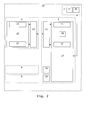
Fig. 2 shows diagrammatically a communication system according to the invention comprising a first device, a second device and a third device. - The
communication system 10 according to the invention shown inFig. 1 comprises afirst device 1 and asecond device 2. - The
first device 1 comprises atransceiver 15 coupled to aprocessor 17. Theprocessor 17 comprises afirst processing part 11 for adjustably processing signals received from thesecond device 2 and a furtherfirst processing part 12 for adjustably processing signals to be transmitted to thesecond device 2. - The
second device 2 comprises aprocessor 27 coupled to atransceiver 25 that is coupled via one or more wired and/or wireless links to thetransceiver 15. Theprocessor 27 comprises asecond processing part 21 for adjustably processing signals to be transmitted to thefirst device 1 and a furthersecond processing part 22 for adjustably processing signals received from thefirst device 1. - The
communication system 10 may further comprise afurther device 8 and/or 9 coupled to afurther transceiver 18 and/or 19 of thefirst device 1, without excluding yet further devices and yet further transceivers not shown. - The first device is for example a DSLAM, or a wireless station, and the second device is for example a DSL gateway/router/modem/bridge or a wireless terminal.
- The
processor 17 further comprises an impulsenoise measuring part 31 for measuring impulse noise characteristics in signals received from thesecond device 2 and anextrapolating part 32 for determining characteristics of impulse noise affecting signals transmitted to thesecond device 2 based on impulse noise characteristics as measured by themeasuring part 31 and anadjusting part 33 for issuing adjustment signals destined for theprocessing parts extrapolating part 32. - The
processing parts - Alternatively the first and
second processing parts - The adjustment signals originating from the adjusting
part 33 might be supplied to theprocessing part 22 via one or more wired and/or wireless links that at least partly coincide with the one or more links between thetransceivers - The
processing parts - The impulse
noise measuring part 31 is arranged to measure characteristics of impulse noise in signals received from thesecond device 2, and for example comprises an erasure detector or a noise detector. - For example, impulse noise measurements comprises impulse noise length, amplitude (or strength), inter-arrival time, time-of-day of occurrence, impulse noise power spectral density. Impulse noise measurements may be further compared and/or combined in a statistical representation with each other (possibly in a weighted way) or otherwise manipulated to further improve the system.
- The extrapolating
part 32 is arranged to extrapolate the characteristics of impulse noise measured by the measuringpart 31 in signals transmitted in one direction of communication, presently from thesecond device 2 to thefirst device 1, to characteristics of impulse noise that affects signals transmitted in the opposite direction of communication, presently from thefirst device 1 to thesecond device 2. - For example, the length and/or inter-arrival time and/or time-of-day of occurrence of impulse noise can be assumed to be identical in both directions of communication, while the power spectral density of impulse noise can be determined by means of linear or polynomial interpolation between disjoint communication bands, or by finding out, among pre-determined impulse noise templates, the closest match with the measured impulse noise, or by finding out, based on loop characteristics, how impulse noise measured on one side of the link will affect the other side of the link.
- It is to be noticed that the characteristics of impulse noise measured by the measuring
part 31 in signals transmitted in one direction of communication on a given subscriber line may be extrapolated to characteristics of impulse noise that affects signals transmitted in the opposite direction on another subscriber line in the same binder. - The adjusting
part 33 is arranged to issue adjustment signals destined for theprocessing parts part 32 and provide a suitable amount of INP to protect against the so-estimated impulse noise. - The
communication system 10 according to the invention shown inFig. 2 corresponds with the one shown inFig. 1 apart from the fact that the extrapolatingpart 32 and the adjustingpart 33 have been shifted out of theprocessor 17 and into athird device 3 coupled to thefirst device 1, such as a network analyzer or a network manager. - The
second device 2 may also implement a noise measuring part, an extrapolating part and an adjusting part for issuing adjustment signals for theprocessing part - In
Fig. 1 and2 , each part shown may be divided into sub-parts, and any two or more parts may be integrated into a new and larger part. Any part shown may comprise hardware and/or software. Theprocessors transceivers
Claims (12)
- A communication system (10) comprising a first device (1) and a second device (2) exchanging signals over a transmission medium, said first device comprising a first processing part (12) for adjustably processing signals to be transmitted over said transmission medium to said second device, and said second device comprising a second processing part (22) for adjustably processing signals received through said transmission medium from said first device,
said first device comprising an impulse noise measuring part (31) for measuring characteristics of impulse noise affecting signals received through said transmission medium from said second device,
characterized in that said communication system further comprises an extrapolating part (32) for determining characteristics of impulse noise affecting signals transmitted over said transmission medium to said second device based on measured impulse noise characteristics determined by said impulse noise measuring part,
and an adjusting part (33) for issuing adjustment signals destined for said first and second processing parts for adjusting their processing based on extrapolated impulse noise characteristics determined by said extrapolating part. - A communication system (10) as defined in claim 1, characterized in that signals transmitted from said first device to said second device over said transmission medium and signals transmitted from said second device to said first device over said transmission medium are multi-carrier signals and make use of disjoint and interleaved frequency bands.
- A communication system (10) as defined in any of the preceding claims, characterized in that said first and second processing parts comprise interleaving parts and/or forward error correction coding parts,
and in that said adjustment signals comprise a minimum impulse noise protection and/or a maximum signal delay and/or a coding parameter. - A communication system (10) as defined in any of the preceding claims, characterized in that said first and second processing parts are adjusted by said adjustment signals at initialization and/or on the fly.
- A communication system (10) as defined in any of the preceding claims, characterized in that said impulse noise measuring part comprises an erasure detector or an increase in noise energy detector or an increase in viterbi output metric detector.
- A communication system (10) as defined in any of the preceding claims, characterized in that said extrapolating and adjusting parts form part of a third device (3) coupled to said first device.
- A communication system (10) as defined in claim 1, 2, 3, 4 or 5, characterized in that said extrapolating and adjusting parts form part of said first device.
- The third device (3) of the communication system as defined in claim 6.
- The first device (1) of the communication system as defined in claim 7.
- A method for use in a communication system comprising a first device (1) and a second device (2) exchanging signals over a transmission medium, said first device comprising a first processing part (12) for adjustably processing signals to be transmitted over said transmission medium to said second device and said second device comprising a second processing part (22) for adjustably processing signals received through said transmission medium from said first device,
said method comprising a first step of, at the first device, measuring characteristics of impulse noise affecting signals received through said transmission medium from said second device,
characterized in that the method further comprises a second step of determining characteristics of impulse noise affecting signals transmitted over said transmission medium to said second device based on measured impulse noise characteristics determined by the first step, and a third step of issuing adjustment signals destined for said first and second processing parts for adjusting their processing based on extrapolated impulse noise characteristics determined by the second step. - A computer program product for performing the steps of the method of claim 10.
- A medium for storing the computer program product of claim 11.
Priority Applications (1)
| Application Number | Priority Date | Filing Date | Title |
|---|---|---|---|
| EP20070290716 EP2001153B1 (en) | 2007-06-08 | 2007-06-08 | Autonomous impulse noise mitigation in communication systems |
Applications Claiming Priority (1)
| Application Number | Priority Date | Filing Date | Title |
|---|---|---|---|
| EP20070290716 EP2001153B1 (en) | 2007-06-08 | 2007-06-08 | Autonomous impulse noise mitigation in communication systems |
Publications (2)
| Publication Number | Publication Date |
|---|---|
| EP2001153A1 true EP2001153A1 (en) | 2008-12-10 |
| EP2001153B1 EP2001153B1 (en) | 2015-01-14 |
Family
ID=38754590
Family Applications (1)
| Application Number | Title | Priority Date | Filing Date |
|---|---|---|---|
| EP20070290716 Not-in-force EP2001153B1 (en) | 2007-06-08 | 2007-06-08 | Autonomous impulse noise mitigation in communication systems |
Country Status (1)
| Country | Link |
|---|---|
| EP (1) | EP2001153B1 (en) |
Citations (1)
| Publication number | Priority date | Publication date | Assignee | Title |
|---|---|---|---|---|
| WO2005086405A2 (en) * | 2004-03-03 | 2005-09-15 | Aware, Inc. | Impulse noise management |
-
2007
- 2007-06-08 EP EP20070290716 patent/EP2001153B1/en not_active Not-in-force
Patent Citations (1)
| Publication number | Priority date | Publication date | Assignee | Title |
|---|---|---|---|---|
| WO2005086405A2 (en) * | 2004-03-03 | 2005-09-15 | Aware, Inc. | Impulse noise management |
Non-Patent Citations (2)
| Title |
|---|
| MOULIN F ET AL: "Discrete-multitone-based ADSL and VDSL systems performance analysis in an impulse noise environment - Advances in communication cables technology", IEE PROCEEDINGS: SCIENCE, MEASUREMENT AND TECHNOLOGY, vol. 150, no. 6, 3 November 2003 (2003-11-03), IEE, STEVENAGE, HERTS, GB, pages 273 - 278, XP006024286, ISSN: 1350-2344 * |
| TOUMPAKARIS D ET AL: "A square distance-based byte-erasure method for reduced-delay protection of DSL systems from non-stationary interference", GLOBECOM'03 - IEEE GLOBAL TELECOMMUNICATIONS CONFERENCE. CONFERENCE PROCEEDINGS, vol. 7 OF 7, 1 December 2003 (2003-12-01) - 5 December 2003 (2003-12-05), NY, US, pages 2114 - 2119, XP010677730, ISBN: 0-7803-7974-8 * |
Also Published As
| Publication number | Publication date |
|---|---|
| EP2001153B1 (en) | 2015-01-14 |
Similar Documents
| Publication | Publication Date | Title |
|---|---|---|
| JP4718479B2 (en) | Adaptive FEC codeword management | |
| US10805040B2 (en) | Impulse noise management | |
| CN102396160B (en) | Method for estimating strength of crosstalk channel | |
| US8553847B2 (en) | Method and device for determining, and method and system for configuring DSL reference virtual noise | |
| JP6296571B2 (en) | Selective channel evaluation | |
| EP2001153B1 (en) | Autonomous impulse noise mitigation in communication systems | |
| Verlinden et al. | Protecting the robustness of ADSL and VDSL DMT modems when applying DSM | |
| Toumpakaris et al. | Digital interference cancellation for DSL using information from the RS decoder | |
| EP2073421A1 (en) | Method and apparatus for transmitting a data signal over a transmission channel | |
| HK1143672A (en) | Adaptive fec coding in dsl systems according to measured impulse noise |
Legal Events
| Date | Code | Title | Description |
|---|---|---|---|
| PUAI | Public reference made under article 153(3) epc to a published international application that has entered the european phase |
Free format text: ORIGINAL CODE: 0009012 |
|
| AK | Designated contracting states |
Kind code of ref document: A1 Designated state(s): AT BE BG CH CY CZ DE DK EE ES FI FR GB GR HU IE IS IT LI LT LU LV MC MT NL PL PT RO SE SI SK TR |
|
| AX | Request for extension of the european patent |
Extension state: AL BA HR MK RS |
|
| 17P | Request for examination filed |
Effective date: 20090610 |
|
| AKX | Designation fees paid |
Designated state(s): AT BE BG CH CY CZ DE DK EE ES FI FR GB GR HU IE IS IT LI LT LU LV MC MT NL PL PT RO SE SI SK TR |
|
| 17Q | First examination report despatched |
Effective date: 20090803 |
|
| RAP1 | Party data changed (applicant data changed or rights of an application transferred) |
Owner name: ALCATEL LUCENT |
|
| 111Z | Information provided on other rights and legal means of execution |
Free format text: AT BE BG CH CY CZ DE DK EE ES FI FR GB GR HU IE IS IT LI LT LU LV MC MT NL PL PT RO SE SI SK TR Effective date: 20130410 |
|
| REG | Reference to a national code |
Ref country code: DE Ref legal event code: R079 Ref document number: 602007040055 Country of ref document: DE Free format text: PREVIOUS MAIN CLASS: H04L0005140000 Ipc: H04L0001000000 |
|
| RAP1 | Party data changed (applicant data changed or rights of an application transferred) |
Owner name: ALCATEL LUCENT |
|
| RIC1 | Information provided on ipc code assigned before grant |
Ipc: H04B 17/00 20060101ALI20140723BHEP Ipc: H04L 5/00 20060101ALI20140723BHEP Ipc: H04L 1/00 20060101AFI20140723BHEP |
|
| GRAP | Despatch of communication of intention to grant a patent |
Free format text: ORIGINAL CODE: EPIDOSNIGR1 |
|
| INTG | Intention to grant announced |
Effective date: 20140909 |
|
| D11X | Information provided on other rights and legal means of execution (deleted) | ||
| GRAS | Grant fee paid |
Free format text: ORIGINAL CODE: EPIDOSNIGR3 |
|
| GRAA | (expected) grant |
Free format text: ORIGINAL CODE: 0009210 |
|
| AK | Designated contracting states |
Kind code of ref document: B1 Designated state(s): AT BE BG CH CY CZ DE DK EE ES FI FR GB GR HU IE IS IT LI LT LU LV MC MT NL PL PT RO SE SI SK TR |
|
| REG | Reference to a national code |
Ref country code: GB Ref legal event code: FG4D |
|
| REG | Reference to a national code |
Ref country code: CH Ref legal event code: EP |
|
| REG | Reference to a national code |
Ref country code: IE Ref legal event code: FG4D |
|
| REG | Reference to a national code |
Ref country code: AT Ref legal event code: REF Ref document number: 707505 Country of ref document: AT Kind code of ref document: T Effective date: 20150215 |
|
| REG | Reference to a national code |
Ref country code: DE Ref legal event code: R096 Ref document number: 602007040055 Country of ref document: DE Effective date: 20150226 |
|
| REG | Reference to a national code |
Ref country code: NL Ref legal event code: VDEP Effective date: 20150114 |
|
| REG | Reference to a national code |
Ref country code: AT Ref legal event code: MK05 Ref document number: 707505 Country of ref document: AT Kind code of ref document: T Effective date: 20150114 |
|
| REG | Reference to a national code |
Ref country code: FR Ref legal event code: PLFP Year of fee payment: 9 |
|
| REG | Reference to a national code |
Ref country code: LT Ref legal event code: MG4D |
|
| PG25 | Lapsed in a contracting state [announced via postgrant information from national office to epo] |
Ref country code: BG Free format text: LAPSE BECAUSE OF FAILURE TO SUBMIT A TRANSLATION OF THE DESCRIPTION OR TO PAY THE FEE WITHIN THE PRESCRIBED TIME-LIMIT Effective date: 20150414 Ref country code: LT Free format text: LAPSE BECAUSE OF FAILURE TO SUBMIT A TRANSLATION OF THE DESCRIPTION OR TO PAY THE FEE WITHIN THE PRESCRIBED TIME-LIMIT Effective date: 20150114 Ref country code: ES Free format text: LAPSE BECAUSE OF FAILURE TO SUBMIT A TRANSLATION OF THE DESCRIPTION OR TO PAY THE FEE WITHIN THE PRESCRIBED TIME-LIMIT Effective date: 20150114 Ref country code: SE Free format text: LAPSE BECAUSE OF FAILURE TO SUBMIT A TRANSLATION OF THE DESCRIPTION OR TO PAY THE FEE WITHIN THE PRESCRIBED TIME-LIMIT Effective date: 20150114 Ref country code: FI Free format text: LAPSE BECAUSE OF FAILURE TO SUBMIT A TRANSLATION OF THE DESCRIPTION OR TO PAY THE FEE WITHIN THE PRESCRIBED TIME-LIMIT Effective date: 20150114 |
|
| PG25 | Lapsed in a contracting state [announced via postgrant information from national office to epo] |
Ref country code: IS Free format text: LAPSE BECAUSE OF FAILURE TO SUBMIT A TRANSLATION OF THE DESCRIPTION OR TO PAY THE FEE WITHIN THE PRESCRIBED TIME-LIMIT Effective date: 20150514 Ref country code: NL Free format text: LAPSE BECAUSE OF FAILURE TO SUBMIT A TRANSLATION OF THE DESCRIPTION OR TO PAY THE FEE WITHIN THE PRESCRIBED TIME-LIMIT Effective date: 20150114 Ref country code: AT Free format text: LAPSE BECAUSE OF FAILURE TO SUBMIT A TRANSLATION OF THE DESCRIPTION OR TO PAY THE FEE WITHIN THE PRESCRIBED TIME-LIMIT Effective date: 20150114 Ref country code: GR Free format text: LAPSE BECAUSE OF FAILURE TO SUBMIT A TRANSLATION OF THE DESCRIPTION OR TO PAY THE FEE WITHIN THE PRESCRIBED TIME-LIMIT Effective date: 20150415 Ref country code: LV Free format text: LAPSE BECAUSE OF FAILURE TO SUBMIT A TRANSLATION OF THE DESCRIPTION OR TO PAY THE FEE WITHIN THE PRESCRIBED TIME-LIMIT Effective date: 20150114 Ref country code: PL Free format text: LAPSE BECAUSE OF FAILURE TO SUBMIT A TRANSLATION OF THE DESCRIPTION OR TO PAY THE FEE WITHIN THE PRESCRIBED TIME-LIMIT Effective date: 20150114 |
|
| REG | Reference to a national code |
Ref country code: DE Ref legal event code: R097 Ref document number: 602007040055 Country of ref document: DE |
|
| PG25 | Lapsed in a contracting state [announced via postgrant information from national office to epo] |
Ref country code: RO Free format text: LAPSE BECAUSE OF FAILURE TO SUBMIT A TRANSLATION OF THE DESCRIPTION OR TO PAY THE FEE WITHIN THE PRESCRIBED TIME-LIMIT Effective date: 20150114 Ref country code: EE Free format text: LAPSE BECAUSE OF FAILURE TO SUBMIT A TRANSLATION OF THE DESCRIPTION OR TO PAY THE FEE WITHIN THE PRESCRIBED TIME-LIMIT Effective date: 20150114 Ref country code: CZ Free format text: LAPSE BECAUSE OF FAILURE TO SUBMIT A TRANSLATION OF THE DESCRIPTION OR TO PAY THE FEE WITHIN THE PRESCRIBED TIME-LIMIT Effective date: 20150114 Ref country code: DK Free format text: LAPSE BECAUSE OF FAILURE TO SUBMIT A TRANSLATION OF THE DESCRIPTION OR TO PAY THE FEE WITHIN THE PRESCRIBED TIME-LIMIT Effective date: 20150114 Ref country code: SK Free format text: LAPSE BECAUSE OF FAILURE TO SUBMIT A TRANSLATION OF THE DESCRIPTION OR TO PAY THE FEE WITHIN THE PRESCRIBED TIME-LIMIT Effective date: 20150114 |
|
| PLBE | No opposition filed within time limit |
Free format text: ORIGINAL CODE: 0009261 |
|
| STAA | Information on the status of an ep patent application or granted ep patent |
Free format text: STATUS: NO OPPOSITION FILED WITHIN TIME LIMIT |
|
| 26N | No opposition filed |
Effective date: 20151015 |
|
| PG25 | Lapsed in a contracting state [announced via postgrant information from national office to epo] |
Ref country code: IT Free format text: LAPSE BECAUSE OF FAILURE TO SUBMIT A TRANSLATION OF THE DESCRIPTION OR TO PAY THE FEE WITHIN THE PRESCRIBED TIME-LIMIT Effective date: 20150114 |
|
| PG25 | Lapsed in a contracting state [announced via postgrant information from national office to epo] |
Ref country code: MC Free format text: LAPSE BECAUSE OF FAILURE TO SUBMIT A TRANSLATION OF THE DESCRIPTION OR TO PAY THE FEE WITHIN THE PRESCRIBED TIME-LIMIT Effective date: 20150114 |
|
| REG | Reference to a national code |
Ref country code: CH Ref legal event code: PL |
|
| PG25 | Lapsed in a contracting state [announced via postgrant information from national office to epo] |
Ref country code: LU Free format text: LAPSE BECAUSE OF FAILURE TO SUBMIT A TRANSLATION OF THE DESCRIPTION OR TO PAY THE FEE WITHIN THE PRESCRIBED TIME-LIMIT Effective date: 20150608 Ref country code: SI Free format text: LAPSE BECAUSE OF FAILURE TO SUBMIT A TRANSLATION OF THE DESCRIPTION OR TO PAY THE FEE WITHIN THE PRESCRIBED TIME-LIMIT Effective date: 20150114 |
|
| REG | Reference to a national code |
Ref country code: IE Ref legal event code: MM4A |
|
| PG25 | Lapsed in a contracting state [announced via postgrant information from national office to epo] |
Ref country code: LI Free format text: LAPSE BECAUSE OF NON-PAYMENT OF DUE FEES Effective date: 20150630 Ref country code: CH Free format text: LAPSE BECAUSE OF NON-PAYMENT OF DUE FEES Effective date: 20150630 Ref country code: IE Free format text: LAPSE BECAUSE OF NON-PAYMENT OF DUE FEES Effective date: 20150608 |
|
| PG25 | Lapsed in a contracting state [announced via postgrant information from national office to epo] |
Ref country code: BE Free format text: LAPSE BECAUSE OF FAILURE TO SUBMIT A TRANSLATION OF THE DESCRIPTION OR TO PAY THE FEE WITHIN THE PRESCRIBED TIME-LIMIT Effective date: 20150114 |
|
| REG | Reference to a national code |
Ref country code: FR Ref legal event code: PLFP Year of fee payment: 10 |
|
| PG25 | Lapsed in a contracting state [announced via postgrant information from national office to epo] |
Ref country code: MT Free format text: LAPSE BECAUSE OF FAILURE TO SUBMIT A TRANSLATION OF THE DESCRIPTION OR TO PAY THE FEE WITHIN THE PRESCRIBED TIME-LIMIT Effective date: 20150114 |
|
| PG25 | Lapsed in a contracting state [announced via postgrant information from national office to epo] |
Ref country code: HU Free format text: LAPSE BECAUSE OF FAILURE TO SUBMIT A TRANSLATION OF THE DESCRIPTION OR TO PAY THE FEE WITHIN THE PRESCRIBED TIME-LIMIT; INVALID AB INITIO Effective date: 20070608 |
|
| REG | Reference to a national code |
Ref country code: FR Ref legal event code: PLFP Year of fee payment: 11 |
|
| PG25 | Lapsed in a contracting state [announced via postgrant information from national office to epo] |
Ref country code: CY Free format text: LAPSE BECAUSE OF FAILURE TO SUBMIT A TRANSLATION OF THE DESCRIPTION OR TO PAY THE FEE WITHIN THE PRESCRIBED TIME-LIMIT Effective date: 20150114 |
|
| PGFP | Annual fee paid to national office [announced via postgrant information from national office to epo] |
Ref country code: FR Payment date: 20170621 Year of fee payment: 11 Ref country code: DE Payment date: 20170621 Year of fee payment: 11 Ref country code: GB Payment date: 20170620 Year of fee payment: 11 |
|
| PG25 | Lapsed in a contracting state [announced via postgrant information from national office to epo] |
Ref country code: TR Free format text: LAPSE BECAUSE OF FAILURE TO SUBMIT A TRANSLATION OF THE DESCRIPTION OR TO PAY THE FEE WITHIN THE PRESCRIBED TIME-LIMIT Effective date: 20150114 |
|
| PG25 | Lapsed in a contracting state [announced via postgrant information from national office to epo] |
Ref country code: PT Free format text: LAPSE BECAUSE OF FAILURE TO SUBMIT A TRANSLATION OF THE DESCRIPTION OR TO PAY THE FEE WITHIN THE PRESCRIBED TIME-LIMIT Effective date: 20150114 |
|
| REG | Reference to a national code |
Ref country code: DE Ref legal event code: R119 Ref document number: 602007040055 Country of ref document: DE |
|
| GBPC | Gb: european patent ceased through non-payment of renewal fee |
Effective date: 20180608 |
|
| PG25 | Lapsed in a contracting state [announced via postgrant information from national office to epo] |
Ref country code: FR Free format text: LAPSE BECAUSE OF NON-PAYMENT OF DUE FEES Effective date: 20180630 Ref country code: DE Free format text: LAPSE BECAUSE OF NON-PAYMENT OF DUE FEES Effective date: 20190101 Ref country code: GB Free format text: LAPSE BECAUSE OF NON-PAYMENT OF DUE FEES Effective date: 20180608 |