EP2001102A2 - Method for controlling frequency converter unit, and frequency converter assembly - Google Patents
Method for controlling frequency converter unit, and frequency converter assembly Download PDFInfo
- Publication number
- EP2001102A2 EP2001102A2 EP08155844A EP08155844A EP2001102A2 EP 2001102 A2 EP2001102 A2 EP 2001102A2 EP 08155844 A EP08155844 A EP 08155844A EP 08155844 A EP08155844 A EP 08155844A EP 2001102 A2 EP2001102 A2 EP 2001102A2
- Authority
- EP
- European Patent Office
- Prior art keywords
- frequency converter
- converter unit
- interface means
- control signals
- user interface
- Prior art date
- Legal status (The legal status is an assumption and is not a legal conclusion. Google has not performed a legal analysis and makes no representation as to the accuracy of the status listed.)
- Withdrawn
Links
Images
Classifications
-
- H—ELECTRICITY
- H02—GENERATION; CONVERSION OR DISTRIBUTION OF ELECTRIC POWER
- H02M—APPARATUS FOR CONVERSION BETWEEN AC AND AC, BETWEEN AC AND DC, OR BETWEEN DC AND DC, AND FOR USE WITH MAINS OR SIMILAR POWER SUPPLY SYSTEMS; CONVERSION OF DC OR AC INPUT POWER INTO SURGE OUTPUT POWER; CONTROL OR REGULATION THEREOF
- H02M5/00—Conversion of AC power input into AC power output, e.g. for change of voltage, for change of frequency, for change of number of phases
-
- H—ELECTRICITY
- H02—GENERATION; CONVERSION OR DISTRIBUTION OF ELECTRIC POWER
- H02J—ELECTRIC POWER NETWORKS; CIRCUIT ARRANGEMENTS OR SYSTEMS FOR SUPPLYING OR DISTRIBUTING ELECTRIC POWER; SYSTEMS FOR STORING ELECTRIC ENERGY
- H02J3/00—Circuit arrangements for AC mains or AC distribution networks
- H02J3/02—Circuit arrangements for AC mains or AC distribution networks using a single network for simultaneous distribution of AC power at different frequencies
-
- G—PHYSICS
- G08—SIGNALLING
- G08C—TRANSMISSION SYSTEMS FOR MEASURED VALUES, CONTROL OR SIMILAR SIGNALS
- G08C19/00—Electric signal transmission systems
-
- H—ELECTRICITY
- H02—GENERATION; CONVERSION OR DISTRIBUTION OF ELECTRIC POWER
- H02J—ELECTRIC POWER NETWORKS; CIRCUIT ARRANGEMENTS OR SYSTEMS FOR SUPPLYING OR DISTRIBUTING ELECTRIC POWER; SYSTEMS FOR STORING ELECTRIC ENERGY
- H02J13/00—Circuit arrangements for providing remote monitoring or remote control of equipment in a power distribution network
- H02J13/13—Circuit arrangements for providing remote monitoring or remote control of equipment in a power distribution network characterised by the transmission of data to equipment in the power network
- H02J13/1311—Circuit arrangements for providing remote monitoring or remote control of equipment in a power distribution network characterised by the transmission of data to equipment in the power network using the power network as support for the transmission
-
- H—ELECTRICITY
- H04—ELECTRIC COMMUNICATION TECHNIQUE
- H04B—TRANSMISSION
- H04B3/00—Line transmission systems
- H04B3/54—Systems for transmission via power distribution lines
- H04B3/56—Circuits for coupling, blocking, or by-passing of signals
-
- H—ELECTRICITY
- H02—GENERATION; CONVERSION OR DISTRIBUTION OF ELECTRIC POWER
- H02M—APPARATUS FOR CONVERSION BETWEEN AC AND AC, BETWEEN AC AND DC, OR BETWEEN DC AND DC, AND FOR USE WITH MAINS OR SIMILAR POWER SUPPLY SYSTEMS; CONVERSION OF DC OR AC INPUT POWER INTO SURGE OUTPUT POWER; CONTROL OR REGULATION THEREOF
- H02M1/00—Details of apparatus for conversion
- H02M1/0003—Details of control, feedback or regulation circuits
- H02M1/0009—Devices or circuits for detecting current in a converter
-
- H—ELECTRICITY
- H04—ELECTRIC COMMUNICATION TECHNIQUE
- H04B—TRANSMISSION
- H04B2203/00—Indexing scheme relating to line transmission systems
- H04B2203/54—Aspects of powerline communications not already covered by H04B3/54 and its subgroups
- H04B2203/5462—Systems for power line communications
- H04B2203/5483—Systems for power line communications using coupling circuits
Definitions
- the invention relates to the control of frequency converters.
- a conventional frequency converter assembly the user interface means of the frequency converter unit is arranged in association with the frequency converter unit.
- a problem with this kind of arrangement is that if the frequency converter unit is inconveniently placed, for example high up, it is difficult for the user to control the frequency converter unit.
- the object of the invention is achieved by a method and a frequency converter assembly characterized by what is stated in the independent claims.
- the preferred embodiments of the invention are disclosed in the dependent claims.
- the invention is based on the idea of controlling the frequency converter unit by supplying the control signals through an inductive connection to a wire connected to the input connection or the output connection of the frequency converter unit, the control signals being supplied to the frequency converter unit over the wire in question.
- the control signals may travel in an electric wire between the feeder network and the frequency converter unit, for example, or in an electric wire between the frequency converter unit and its load.
- a single user interface means is used for controlling a plural number of frequency converter units connected to one and the same electric power network, the control signals travelling through the network.
- An advantage of the invention is that if necessary the user interface means of the frequency converter unit may be placed at a distance from the frequency converter unit.
- the user interface means may be movable.
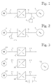
- FIG. 1 illustrates a frequency converter assembly according to an embodiment of the invention, comprising a frequency converter unit 2, a user interface means 4 and an electric motor 6 fed by the frequency converter unit.
- a feeder network 8 supplies electric power at an input frequency to an input connection of the frequency converter unit 2 over a feeder cable 10.
- the frequency converter unit 2 supplies electric power at an output frequency from its output connection to the electric motor over a motor cable 12.
- the user interface means 4 controls the frequency converter unit 2 by transmitting control signals thereto over the feeder cable 10. The control signals travel from the user interface means 4 to the feeder cable 10 via a signal interface means 14.
- Figure 2 illustrates a frequency converter assembly, which is a variation of the assembly shown in Figure 1 .
- the user interface 4 of the assembly of Figure 2 is connected to the motor cable 12, i.e. the user interface means 4 transmits the control signals to the frequency converter unit 2 over the motor cable 12.
- the signal interface means carrying the control signals from the user interface means 4 to the motor cable 12 is denoted with reference numeral 14'. Otherwise the frequency converter assemblies of Figures 1 and 2 are identical.
- the signal interface means 14 and 14' are configured to be inductively connected to the cable of the frequency converter unit 2.
- This inductive connection may be implemented for example by providing the signal interface means with an openable induction loop, which in its open position may be placed around the cable, whereas in its closed position it is arranged to supply control signals to an electric wire inside the induction loop.
- the operating principle of an openable induction loop is generally known from clip-on meters.
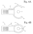
- FIGs 4A and 4B illustrate a user interface means 4" according to an embodiment of the invention, provided with a signal interface means 14" comprising an openable induction loop.
- the user interface means 4" comprises an actuation member 42", and by pressing the actuation member the user is able to open the jaws 141" and 142" of the induction loop.
- the jaws 141" and 142" of the openable induction loop are in the open position, in which the distance between the tips of the jaws 141" and 142" is substantially greater than the diameter of the feeder cable 10.
- FIG 4B the jaws 141" and 142" of the openable induction loop are in the closed position and the feeder cable 10 is inside the induction loop formed by the jaws 141" and 142", thus allowing control signals to be supplied inductively into the feeder cable 10.
- Figure 3 illustrates a frequency converter assembly, in which a single user interface means 104 is used for controlling three frequency converter units 102, 202 and 302 connected to one and the same feeder network 108.
- the frequency converter unit 102 is supplied with electric power from the feeder network 108 over a feeder cable 110, the frequency converter unit 102 feeding an electric motor 106 over a motor cable 112.
- the frequency converter unit 202 is supplied with electric power from the feeder network 108 over a feeder cable 210, the frequency converter unit 202 feeding an electric motor 206 over a motor cable 212.
- the feeder cable of the frequency converter unit 302 is denoted by reference numeral 310, its motor cable by reference numeral 312, and the electric motor to be fed by reference numeral 306.
- the user interface means 104 is inductively connected to the feeder network 108 through a signal interface means 114.
- the user interface means 4, 104 of Figures 1 to 3 may be configured to carry out bi-directional data transfer in which they are not only capable of transmitting control signals to the frequency converter unit but also receiving response signals from the frequency converter unit.
- the response signals may contain data on the actual values of the current and voltage supplied by the frequency converter, for example, and on any failure signals of the frequency converter unit.
- the user interface means of the invention may be arranged to transmit control signals to the frequency converter unit by using a known modulation, such as PSK, ASK, FSK or PAM, together with a known protocol.
- a known modulation such as PSK, ASK, FSK or PAM
- the modulated control signal is supplied over a voltage wave of a basic frequency in the feeder network.
- the modulated control signal is supplied over a voltage wave of an output frequency generated by the frequency converter unit.
- the user interface means of the frequency converter assembly may be configured so as to allow the control signals it transmits to travel through transformers and other similar devices producing a galvanic isolation.
Landscapes
- Engineering & Computer Science (AREA)
- Power Engineering (AREA)
- Computer Networks & Wireless Communication (AREA)
- Signal Processing (AREA)
- Physics & Mathematics (AREA)
- General Physics & Mathematics (AREA)
- Inverter Devices (AREA)
- Near-Field Transmission Systems (AREA)
- Ac-Ac Conversion (AREA)
- Supply And Distribution Of Alternating Current (AREA)
Abstract
Description
- The invention relates to the control of frequency converters.
- In a conventional frequency converter assembly the user interface means of the frequency converter unit is arranged in association with the frequency converter unit. A problem with this kind of arrangement is that if the frequency converter unit is inconveniently placed, for example high up, it is difficult for the user to control the frequency converter unit.
- It is an object of the invention to provide a method for controlling a frequency converter unit and a frequency converter assembly that allow the above problem to be solved. The object of the invention is achieved by a method and a frequency converter assembly characterized by what is stated in the independent claims. The preferred embodiments of the invention are disclosed in the dependent claims.
- The invention is based on the idea of controlling the frequency converter unit by supplying the control signals through an inductive connection to a wire connected to the input connection or the output connection of the frequency converter unit, the control signals being supplied to the frequency converter unit over the wire in question.
- The control signals may travel in an electric wire between the feeder network and the frequency converter unit, for example, or in an electric wire between the frequency converter unit and its load. According to an embodiment of the invention a single user interface means is used for controlling a plural number of frequency converter units connected to one and the same electric power network, the control signals travelling through the network.
- An advantage of the invention is that if necessary the user interface means of the frequency converter unit may be placed at a distance from the frequency converter unit. The user interface means may be movable.
- In the following the invention will be described in greater detail with reference to preferred embodiments and the accompanying drawings, in which
-
Figure 1 illustrates a frequency converter assembly with a user interface means coupled to an electric wire between the feeder network and the frequency converter unit; -
Figure 2 illustrates a frequency converter assembly with a user interface means coupled to an electric wire between the frequency converter unit and its load. -
Figure 3 illustrates a frequency converter assembly, in which a single user interface means is used for controlling a plural number of frequency converter units connected to one and the same electric power network. -
Figure 4A illustrates a user interface means provided with an openable induction loop, the induction loop being in its open position; and -
Figure 4B illustrates the user interface means ofFigure 4A with the openable induction loop in its closed position. -
Figure 1 illustrates a frequency converter assembly according to an embodiment of the invention, comprising afrequency converter unit 2, a user interface means 4 and an electric motor 6 fed by the frequency converter unit. A feeder network 8 supplies electric power at an input frequency to an input connection of thefrequency converter unit 2 over afeeder cable 10. Thefrequency converter unit 2 supplies electric power at an output frequency from its output connection to the electric motor over amotor cable 12. The user interface means 4 controls thefrequency converter unit 2 by transmitting control signals thereto over thefeeder cable 10. The control signals travel from the user interface means 4 to thefeeder cable 10 via a signal interface means 14. -
Figure 2 illustrates a frequency converter assembly, which is a variation of the assembly shown inFigure 1 . Instead of being connected to thefeeder cable 10, theuser interface 4 of the assembly ofFigure 2 is connected to themotor cable 12, i.e. the user interface means 4 transmits the control signals to thefrequency converter unit 2 over themotor cable 12. The signal interface means carrying the control signals from the user interface means 4 to themotor cable 12 is denoted with reference numeral 14'. Otherwise the frequency converter assemblies ofFigures 1 and 2 are identical. - The signal interface means 14 and 14' are configured to be inductively connected to the cable of the
frequency converter unit 2. This inductive connection may be implemented for example by providing the signal interface means with an openable induction loop, which in its open position may be placed around the cable, whereas in its closed position it is arranged to supply control signals to an electric wire inside the induction loop. The operating principle of an openable induction loop is generally known from clip-on meters. -
Figures 4A and 4B illustrate a user interface means 4" according to an embodiment of the invention, provided with a signal interface means 14" comprising an openable induction loop. The user interface means 4" comprises anactuation member 42", and by pressing the actuation member the user is able to open thejaws 141" and 142" of the induction loop. InFigure 4A thejaws 141" and 142" of the openable induction loop are in the open position, in which the distance between the tips of thejaws 141" and 142" is substantially greater than the diameter of thefeeder cable 10. InFigure 4B thejaws 141" and 142" of the openable induction loop are in the closed position and thefeeder cable 10 is inside the induction loop formed by thejaws 141" and 142", thus allowing control signals to be supplied inductively into thefeeder cable 10.
Figure 3 illustrates a frequency converter assembly, in which a single user interface means 104 is used for controlling threefrequency converter units same feeder network 108. Thefrequency converter unit 102 is supplied with electric power from thefeeder network 108 over afeeder cable 110, thefrequency converter unit 102 feeding anelectric motor 106 over amotor cable 112. Thefrequency converter unit 202 is supplied with electric power from thefeeder network 108 over afeeder cable 210, thefrequency converter unit 202 feeding anelectric motor 206 over amotor cable 212. The feeder cable of thefrequency converter unit 302 is denoted byreference numeral 310, its motor cable byreference numeral 312, and the electric motor to be fed byreference numeral 306. The user interface means 104 is inductively connected to thefeeder network 108 through a signal interface means 114. - The user interface means 4, 104 of
Figures 1 to 3 may be configured to carry out bi-directional data transfer in which they are not only capable of transmitting control signals to the frequency converter unit but also receiving response signals from the frequency converter unit. The response signals may contain data on the actual values of the current and voltage supplied by the frequency converter, for example, and on any failure signals of the frequency converter unit. - The user interface means of the invention may be arranged to transmit control signals to the frequency converter unit by using a known modulation, such as PSK, ASK, FSK or PAM, together with a known protocol. In the embodiments of
Figures 1 and 3 the modulated control signal is supplied over a voltage wave of a basic frequency in the feeder network. In the embodiment ofFigure 2 the modulated control signal is supplied over a voltage wave of an output frequency generated by the frequency converter unit. - The user interface means of the frequency converter assembly may be configured so as to allow the control signals it transmits to travel through transformers and other similar devices producing a galvanic isolation.
- A person skilled in the art will find it apparent that the basic idea of the invention may be implemented in various ways. The invention and its embodiments are therefore not restricted to the above examples but may vary within the scope of the claims.
Claims (3)
- A method for controlling a frequency converter unit, the frequency converter unit (2) containing an input connection for supplying electric power at an input frequency to the frequency converter unit, and an output connection for supplying electric power at an output frequency from the frequency converter unit, the method comprising a control step, in which the frequency converter unit (2) is controlled by means of control signals, the method being characterized in that in the control step the control signals are supplied through an inductive connection to at least one wire (10, 12) connected to the input connection or the output connection of the frequency converter unit (2) for transmitting electric power, the control signals being supplied to the frequency converter unit (2) over the at least one wire (10, 12).
- A frequency converter assembly comprising a frequency converter unit (2, 102) and a user interface means (4; 4"; 104), the frequency converter unit (2, 102) containing an input connection for supplying electric power at an input frequency to the frequency converter unit, and an output connection for supplying electric power at an output frequency from the frequency converter unit, the user interface means (4; 4"; 104) being configured to control the frequency converter unit (2; 102) by means of control signals, characterized in that the user interface means (4; 4"; 104) is arranged to transmit control signals to the frequency converter unit (2, 102) through the input connection or the output connection of the frequency converter unit, the user interface means (4; 4"; 104) being arranged to be inductively connected to at least one wire (10, 12; 110, 112), which is connected to the input connection or the output connection of the frequency converter unit (2; 102) for transmitting electric power, to allow the control signals to be transmitted to the frequency converter unit (2; 102) over the at least one wire (10, 12; 110, 112).
- A frequency converter assembly according to claim 2, characterized in that the frequency converter assembly further comprises a signal interface means (14, 14"; 114) arranged to convey the control signals from the user interface means (4; 4"; 104) to the at least one wire (10, 12; 110, 112), the signal interface means (14; 14"; 114) comprising an openable induction loop having an open position and a closed position, the open position being arranged for setting the openable induction loop around the at least one wire (10,12; 110; 112) and the closed position being arranged for supplying control signals to the at least one wire (10, 12; 110, 112) inside the openable induction loop.
Applications Claiming Priority (1)
| Application Number | Priority Date | Filing Date | Title |
|---|---|---|---|
| FI20075418A FI121522B (en) | 2007-06-06 | 2007-06-06 | Procedure for controlling frequency converter unit and frequency converter assembly |
Publications (2)
| Publication Number | Publication Date |
|---|---|
| EP2001102A2 true EP2001102A2 (en) | 2008-12-10 |
| EP2001102A3 EP2001102A3 (en) | 2016-07-06 |
Family
ID=38212389
Family Applications (1)
| Application Number | Title | Priority Date | Filing Date |
|---|---|---|---|
| EP08155844.7A Withdrawn EP2001102A3 (en) | 2007-06-06 | 2008-05-08 | Method for controlling frequency converter unit, and frequency converter assembly |
Country Status (4)
| Country | Link |
|---|---|
| US (1) | US8755210B2 (en) |
| EP (1) | EP2001102A3 (en) |
| CN (1) | CN101320942B (en) |
| FI (1) | FI121522B (en) |
Cited By (1)
| Publication number | Priority date | Publication date | Assignee | Title |
|---|---|---|---|---|
| EP2302780A3 (en) * | 2009-09-24 | 2016-11-02 | ABB Oy | Frequency converter |
Families Citing this family (5)
| Publication number | Priority date | Publication date | Assignee | Title |
|---|---|---|---|---|
| US10281503B2 (en) * | 2016-11-11 | 2019-05-07 | Fluke Corporation | Non-contact voltage measurement system using multiple capacitors |
| US10352967B2 (en) | 2016-11-11 | 2019-07-16 | Fluke Corporation | Non-contact electrical parameter measurement systems |
| US10677876B2 (en) * | 2018-05-09 | 2020-06-09 | Fluke Corporation | Position dependent non-contact voltage and current measurement |
| US20240348171A1 (en) * | 2023-04-12 | 2024-10-17 | DG Matrix, Inc. | Multiport transformer enabled modular multiport power conversion system |
| US12542440B2 (en) | 2023-04-12 | 2026-02-03 | DG Matrix, Inc. | Resilient on-site microgrid system |
Family Cites Families (21)
| Publication number | Priority date | Publication date | Assignee | Title |
|---|---|---|---|---|
| US6452482B1 (en) | 1999-12-30 | 2002-09-17 | Ambient Corporation | Inductive coupling of a data signal to a power transmission cable |
| DE2825240C2 (en) * | 1978-06-08 | 1983-09-22 | Siemens AG, 1000 Berlin und 8000 München | Ripple control system |
| US5373277A (en) * | 1991-08-07 | 1994-12-13 | Mitsubishi Denki Kabushiki Kaisha | Signal discriminator |
| JP3637982B2 (en) * | 1995-06-27 | 2005-04-13 | 株式会社荏原電産 | Inverter-driven pump control system |
| JP3646741B2 (en) | 1995-06-27 | 2005-05-11 | 株式会社荏原電産 | Inverter-driven pump control system |
| US5614811A (en) * | 1995-09-26 | 1997-03-25 | Dyalem Concepts, Inc. | Power line control system |
| US6043640A (en) * | 1997-10-29 | 2000-03-28 | Fluke Corporation | Multimeter with current sensor |
| US6731102B2 (en) * | 2001-01-31 | 2004-05-04 | Ideal Industries, Inc. | Electronic test instrument with extended functions |
| US6768700B2 (en) * | 2001-02-22 | 2004-07-27 | Schlumberger Technology Corporation | Method and apparatus for communications in a wellbore |
| US6888263B2 (en) * | 2001-05-23 | 2005-05-03 | Ebara Corporation | Gas turbine generator |
| WO2003094365A2 (en) * | 2002-05-03 | 2003-11-13 | Ambient Corporation | Construction of medium voltage power line data couplers |
| US7102478B2 (en) * | 2002-06-21 | 2006-09-05 | Current Technologies, Llc | Power line coupling device and method of using the same |
| WO2004077637A1 (en) * | 2003-02-20 | 2004-09-10 | Ebara Corporation | Power generating apparatus |
| US20070007969A1 (en) * | 2003-09-19 | 2007-01-11 | Ebara Densan Ltd. | Circuit and system for detecting dc component in inverter device for grid-connection |
| EP1536572A1 (en) * | 2003-11-26 | 2005-06-01 | ADS Enterprises NZ Ltd. | Power line communication system |
| US8938021B1 (en) * | 2004-05-06 | 2015-01-20 | Paul Shala Henry | Outbound interference reduction in a broadband powerline system |
| US7288929B2 (en) * | 2005-07-19 | 2007-10-30 | Seektech, Inc. | Inductive clamp for applying signal to buried utilities |
| ATE463091T1 (en) * | 2005-07-29 | 2010-04-15 | Grundfos Management As | METHOD FOR DATA TRANSMISSION BETWEEN A PUMP UNIT AND A CONTROL DEVICE AND AN APPROPRIATELY DESIGNED PUMP SYSTEM |
| KR100657873B1 (en) * | 2005-12-21 | 2006-12-15 | 한국전기연구원 | Remote monitoring control system for distributed generation using power line communication method |
| US7439726B2 (en) * | 2006-04-27 | 2008-10-21 | Fluke Corporation | Electrical measuring instrument having detachable current clamp probe |
| US7557559B1 (en) * | 2006-06-19 | 2009-07-07 | Seektech, Inc. | Compact line illuminator for locating buried pipes and cables |
-
2007
- 2007-06-06 FI FI20075418A patent/FI121522B/en not_active IP Right Cessation
-
2008
- 2008-05-08 EP EP08155844.7A patent/EP2001102A3/en not_active Withdrawn
- 2008-06-04 US US12/155,456 patent/US8755210B2/en not_active Expired - Fee Related
- 2008-06-04 CN CN200810108991XA patent/CN101320942B/en not_active Expired - Fee Related
Cited By (1)
| Publication number | Priority date | Publication date | Assignee | Title |
|---|---|---|---|---|
| EP2302780A3 (en) * | 2009-09-24 | 2016-11-02 | ABB Oy | Frequency converter |
Also Published As
| Publication number | Publication date |
|---|---|
| US20080310206A1 (en) | 2008-12-18 |
| FI20075418L (en) | 2008-12-07 |
| CN101320942B (en) | 2013-01-02 |
| US8755210B2 (en) | 2014-06-17 |
| EP2001102A3 (en) | 2016-07-06 |
| CN101320942A (en) | 2008-12-10 |
| FI121522B (en) | 2010-12-15 |
| FI20075418A0 (en) | 2007-06-06 |
Similar Documents
| Publication | Publication Date | Title |
|---|---|---|
| EP2001102A2 (en) | Method for controlling frequency converter unit, and frequency converter assembly | |
| US7639994B2 (en) | RF power transmission network and method | |
| US20160285311A1 (en) | Wireless power supply system, power transmitting apparatus and power receiving apparatus | |
| EP3120964A1 (en) | Wireless and powerline communications in a welding-type system | |
| US6563420B2 (en) | Power line communications apparatus and method | |
| EP2916429A1 (en) | Multiplexed transmission system by means of wireless electrical power transmission, and transmitting-side multiplexed transmission device | |
| US20140064388A1 (en) | Power line communication system for vehicle | |
| EP1810631A3 (en) | System for transmitting data across patient isolation barrier | |
| CA2631758A1 (en) | Control channel for vehicle systems using the vehicle's power distribution system | |
| CN112511016A (en) | Delivering wireless or wired power using a controllable power adapter | |
| US8928181B2 (en) | Method and apparatus for transmission of energy and data | |
| AU2002222031A1 (en) | Method and device for remote and non-connected implementation of an implant and implant implemented by said device | |
| KR101278125B1 (en) | Dimming control apparatus using sensing of volts alternating current in power line communication | |
| CN119401675A (en) | Wireless power transceiver and related method | |
| NO334200B1 (en) | System for communicating over an energy cable in a petroleum well | |
| EP1014535A3 (en) | Uninterrupted power supply system | |
| CN105375648A (en) | Wireless LED driving system | |
| US10003383B2 (en) | Power transmission system | |
| KR101718312B1 (en) | Wireless Power Transmitter and Wireless Power Receiver | |
| GB2517727A (en) | Digitally generated communication on power based on separately modulated power and data signals | |
| CN109617379A (en) | For controlling the method and frequency converter assembly of frequency converter unit | |
| US20140159510A1 (en) | System for supplying ac power to a display via a low voltage cable | |
| CN106717115B (en) | Lighting circuit is driven with wireless control | |
| CN210780235U (en) | Wireless charging system for lighting device | |
| EP2154791A1 (en) | Method and system for inductively transmitting energy and information |
Legal Events
| Date | Code | Title | Description |
|---|---|---|---|
| PUAI | Public reference made under article 153(3) epc to a published international application that has entered the european phase |
Free format text: ORIGINAL CODE: 0009012 |
|
| AK | Designated contracting states |
Kind code of ref document: A2 Designated state(s): AT BE BG CH CY CZ DE DK EE ES FI FR GB GR HR HU IE IS IT LI LT LU LV MC MT NL NO PL PT RO SE SI SK TR |
|
| AX | Request for extension of the european patent |
Extension state: AL BA MK RS |
|
| PUAL | Search report despatched |
Free format text: ORIGINAL CODE: 0009013 |
|
| AK | Designated contracting states |
Kind code of ref document: A3 Designated state(s): AT BE BG CH CY CZ DE DK EE ES FI FR GB GR HR HU IE IS IT LI LT LU LV MC MT NL NO PL PT RO SE SI SK TR |
|
| AX | Request for extension of the european patent |
Extension state: AL BA MK RS |
|
| RIC1 | Information provided on ipc code assigned before grant |
Ipc: H02M 1/00 20060101ALI20160530BHEP Ipc: H04B 3/54 20060101ALI20160530BHEP Ipc: H02J 13/00 20060101AFI20160530BHEP |
|
| AKY | No designation fees paid | ||
| AXX | Extension fees paid |
Extension state: MK Extension state: RS Extension state: AL Extension state: BA |
|
| REG | Reference to a national code |
Ref country code: DE Ref legal event code: R108 |
|
| STAA | Information on the status of an ep patent application or granted ep patent |
Free format text: STATUS: THE APPLICATION IS DEEMED TO BE WITHDRAWN |
|
| 18D | Application deemed to be withdrawn |
Effective date: 20161201 |