EP2000786B1 - Thermal imaging device with calibrating functionality - Google Patents
Thermal imaging device with calibrating functionality Download PDFInfo
- Publication number
- EP2000786B1 EP2000786B1 EP08010254.4A EP08010254A EP2000786B1 EP 2000786 B1 EP2000786 B1 EP 2000786B1 EP 08010254 A EP08010254 A EP 08010254A EP 2000786 B1 EP2000786 B1 EP 2000786B1
- Authority
- EP
- European Patent Office
- Prior art keywords
- reflector
- imaging device
- thermal imaging
- detector
- microspheres
- Prior art date
- Legal status (The legal status is an assumption and is not a legal conclusion. Google has not performed a legal analysis and makes no representation as to the accuracy of the status listed.)
- Active
Links
- 238000001931 thermography Methods 0.000 title claims description 31
- 239000004005 microsphere Substances 0.000 claims description 35
- 230000005855 radiation Effects 0.000 claims description 24
- PCHJSUWPFVWCPO-UHFFFAOYSA-N gold Chemical compound [Au] PCHJSUWPFVWCPO-UHFFFAOYSA-N 0.000 claims description 13
- 238000010438 heat treatment Methods 0.000 claims description 13
- 239000010931 gold Substances 0.000 claims description 10
- 229910052737 gold Inorganic materials 0.000 claims description 10
- 239000011248 coating agent Substances 0.000 claims 2
- 238000000576 coating method Methods 0.000 claims 2
- 230000003287 optical effect Effects 0.000 description 8
- 238000001514 detection method Methods 0.000 description 6
- 238000005259 measurement Methods 0.000 description 6
- 239000011888 foil Substances 0.000 description 5
- 229920003229 poly(methyl methacrylate) Polymers 0.000 description 4
- 239000004926 polymethyl methacrylate Substances 0.000 description 4
- 239000010410 layer Substances 0.000 description 3
- 230000008016 vaporization Effects 0.000 description 3
- 238000009834 vaporization Methods 0.000 description 3
- 238000003384 imaging method Methods 0.000 description 2
- 238000007740 vapor deposition Methods 0.000 description 2
- 238000001816 cooling Methods 0.000 description 1
- 230000001419 dependent effect Effects 0.000 description 1
- 238000004519 manufacturing process Methods 0.000 description 1
- 239000000463 material Substances 0.000 description 1
- 239000002184 metal Substances 0.000 description 1
- 229910052751 metal Inorganic materials 0.000 description 1
- 230000000737 periodic effect Effects 0.000 description 1
- 229920000058 polyacrylate Polymers 0.000 description 1
- 230000001105 regulatory effect Effects 0.000 description 1
- 239000002356 single layer Substances 0.000 description 1
- 230000007704 transition Effects 0.000 description 1
Images


Classifications
-
- G—PHYSICS
- G01—MEASURING; TESTING
- G01J—MEASUREMENT OF INTENSITY, VELOCITY, SPECTRAL CONTENT, POLARISATION, PHASE OR PULSE CHARACTERISTICS OF INFRARED, VISIBLE OR ULTRAVIOLET LIGHT; COLORIMETRY; RADIATION PYROMETRY
- G01J5/00—Radiation pyrometry, e.g. infrared or optical thermometry
- G01J5/02—Constructional details
- G01J5/06—Arrangements for eliminating effects of disturbing radiation; Arrangements for compensating changes in sensitivity
- G01J5/061—Arrangements for eliminating effects of disturbing radiation; Arrangements for compensating changes in sensitivity by controlling the temperature of the apparatus or parts thereof, e.g. using cooling means or thermostats
-
- G—PHYSICS
- G01—MEASURING; TESTING
- G01J—MEASUREMENT OF INTENSITY, VELOCITY, SPECTRAL CONTENT, POLARISATION, PHASE OR PULSE CHARACTERISTICS OF INFRARED, VISIBLE OR ULTRAVIOLET LIGHT; COLORIMETRY; RADIATION PYROMETRY
- G01J5/00—Radiation pyrometry, e.g. infrared or optical thermometry
- G01J5/02—Constructional details
- G01J5/08—Optical arrangements
- G01J5/0808—Convex mirrors
-
- G—PHYSICS
- G01—MEASURING; TESTING
- G01J—MEASUREMENT OF INTENSITY, VELOCITY, SPECTRAL CONTENT, POLARISATION, PHASE OR PULSE CHARACTERISTICS OF INFRARED, VISIBLE OR ULTRAVIOLET LIGHT; COLORIMETRY; RADIATION PYROMETRY
- G01J5/00—Radiation pyrometry, e.g. infrared or optical thermometry
- G01J5/52—Radiation pyrometry, e.g. infrared or optical thermometry using comparison with reference sources, e.g. disappearing-filament pyrometer
- G01J5/54—Optical arrangements
Definitions
- the present invention relates to a thermal imaging device with calibration functionality.
- Thermal imaging devices are used to detect heat-emitting objects and are particularly advantageous for use in the dark.
- a thermal imager typically includes an infrared detector having a plurality of individual sensors arranged one-dimensionally in rows two-dimensionally in a surface. The infrared detector is cooled in order to increase the contrast and reduce the heat loss.
- An optical system is used for focusing and optionally for changing the focal length of the thermal imaging device.
- the individual sensors of an infrared detector show different imaging properties. This means that the sensors produce different electrical output signals for the same amount of incident photons. These differences must be measured as part of a calibration and then corrected. Since the imaging characteristics of the thermal imaging device's individual sensors may change over time, a periodic calibration is necessary, for example, after each power-up or after extended use.
- This reference surface preferably has the temperature of the thermal imaging device to be detected Image areas on. Typically, this temperature is lower than the unit's internal temperature, as it comes to self-heating within the device.
- Thermal imaging devices with cube corner reflectors are for example from the documents EP 0 277 696 B1 or WO 03/076885 A1 known.
- the document WO 03/089963 A1 relates to an acrylic polymer overcoat for a retroreflective sheeting.
- the document WO 00/50931 A1 discloses a retroreflective article having cube corners or microspheres.
- the known reflectors are large, require high precision in the production and do not produce a particularly homogeneous temperature distribution. It is therefore the object of the present invention to provide a thermal imaging device with calibration functionality, the reflector does not have the aforementioned disadvantages.
- a generic thermal imaging device with calibration functionality has a cooled infrared detector and a reflector for reflecting the heat radiation of the detector to the detection range of the detector.
- the reflector has microspheres.
- the microspheres provide for a low overall height for a particularly diffuse reflection of heat radiation, so that the reflector has a homogeneous apparent temperature.
- the reflection is either simple, ie directly from a microsphere back to the detector, or a multiple reflection first between two or more microspheres and then back to the detector.
- the microspheres consist for example of the material polymethyl methacrylate (PMMA or acrylic glass). Such microspheres are lightweight, resulting in a low weight of the thermal imaging device. They are also transparent to infrared radiation. In the detection area of the thermal imaging device, so that different arrangements of the microspheres are possible.
- the balls are preferably arranged in a single layer, in particular in a flat surface.
- the microspheres are arranged on a mirrored carrier foil.
- the microspheres are transparent, the carrier film is preferably a gold foil or a foil of another suitable metal.
- the microspheres deform the carrier film in such a way that the film bears against the microspheres on a part of the spherical surface, a so-called spherical cap.
- the microspheres are therefore embedded in the reflective support film. The reflection takes place at the curved interface between the microsphere and the carrier foil.
- Such a design of the reflector is particularly suitable for infrared radiation in the wavelength range between 3 .mu.m and 5 .mu.m.
- the microspheres are arranged on a carrier foil and provided with a gold vaporization.
- the gold vaporization of the microspheres preferably causes a closed gold layer with locally curved surface. Not only are the surfaces of the microspheres provided with the gold layer, but the gold layer also continues in the interspaces.
- Such a design of the reflector is particularly suitable for infrared radiation in the wavelength range between 8 .mu.m and 12 .mu.m.
- the microspheres preferably have different diameters, for example between 50 ⁇ m and 90 ⁇ m, for example with an average spherical diameter of 70 ⁇ m. Due to the different ball sizes in the reflector, the reflection is particularly diffuse and the apparent temperature of the reflector particularly homogeneous. A variation of the diameter sizes in particular prevents diffraction patterns on the detector surface.
- At least two adjacent microspheres touch each other.
- a particularly well reflective surface is created, which also has a higher mechanical stability.
- the thermal imaging device preferably has means for introducing the reflector into the beam path of the thermal imaging device.
- This is, for example, an arm on which the reflector is arranged, which is pivoted or moved in the beam path.
- Possible positions of the reflector are between the infrared detector and the optical system, within the optical system, for example between two lenses, or even in front of the front lens of the optical system.
- the front lens is the lens of the optical system farthest from the infrared detector.
- the infrared detector can be aligned with the reflector.
- the reflector is arranged stationary in the thermal imaging device and the infrared detector is pivoted, for example, to the reflector.
- the optical system is also completely or partially aligned with the reflector.
- the thermal imaging device has a heating element for heating the reflector.
- the heating element is, for example, a Peltier element, a heating wire or a heating foil.
- the distance of the reflector from the detector is variable. With the distance of the reflector from the detector, the reflection properties change, so that the heat radiation intensity on the detector can be regulated. In particular, the ratio of the infrared radiation reflected from the environment to the detector changes to the infrared radiation originating from the detector and reflected back to the detector. Thus, calibration measurements at different temperature levels are possible without heating the reflector.
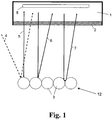
- the thermal imaging device 1 in consists essentially of an infrared detector 8 with a plurality of individual detectors, an optical system, not shown, and a reflector 12 for thermal radiation.
- the optical system is used for focusing and optionally for adjusting the focal length of the thermal imaging device 1.
- the infrared detector 8 is cooled by means of a cooling system, not shown in the figures.
- the arrows in the figures symbolize the beam path of the heat radiation. Identical elements are provided in the figures with the same reference numerals.
- the reflector 12 in FIG. 1 consists of microspheres 3, which are arranged on a carrier film 9 and provided with a gold vaporization 10 (see FIG. 3 ).
- the gold vapor deposition 10 covers the surface parts of the microspheres 3 facing the detector 8 and those parts of the carrier film 9 which are not covered by spheres. Due to its surface shape, the gold vapor deposition 10 reflects the heat radiation of the infrared detector 8, which exits an opening 2 of the thermal imaging device 1, diffusely back to the infrared detector 8. The reflection takes place at the side of the microspheres 3 facing the detector 8.
- the radiation indicated by the arrow 5 is reflected back directly into the detector 8 in itself.
- the indicated by the arrow 6 radiation is reflected back directly to another point of the detector 8 as its starting point.
- the radiation indicated by the arrow 7 is first from a first ball 3 to a second ball 3 and from there to the detector. 8 reflected.
- the indicated by the arrow 4 radiation from the environment is also reflected on the detector 8.
- the reflector 12 reflects the heat radiation, ie infrared radiation, of the cooled infrared detector 8 and thus the temperature of the detector back into the detection range of the detector 8.
- the reflector 12 has a homogeneous apparent temperature which is below the actual temperature of the reflector 12 of the thermal imaging device 1.
- an electronic unit (not shown) reads the output values of the individual sensors of the infrared detector 8. From the output values, the electronics calculates correction parameters for a correction function.
- the correction function calculates a homogeneous thermal image from these parameters and the output values of the individual sensors of the infrared detector 8. The correction parameters thus determined are used during operation of the thermal imaging device 1 to correct the output values of the infrared detector 8.
- the reflector 12 is removed from the detection range of the thermal imaging device 1.
- corresponding means are provided in the thermal imaging device, which are not shown in the figures.
- a heating element is arranged on the reflector 12. If the heating element is turned on, it heats the reflector 12. This generates additional heat radiation, which impinges on the infrared detector 8 during the calibration measurement.
- the apparent temperature of the reflector 12, which the infrared detector 8 detects, is higher than when the heating element is not switched on. With the help of the heating element therefore calibration measurements at different apparent temperatures are feasible.
- calibration measurements can be performed at different apparent temperatures by varying the distance of the reflector 12 from the infrared detector 8.
- the means are used also serve to remove the reflector 12 from the detection range of the thermal imaging device, or separate means.
- FIG. 4 shows an alternative embodiment of the reflector 12, are embedded in the transparent microspheres 3 of acrylic glass in a gold foil 11.
- the microspheres 3 deform the surface of the film 11, so that the film 11 fits tightly against the surfaces of the microspheres and thereby forms spherical caps.
- the reflection takes place at the side of the microspheres 3 facing away from the detector 8, at the transition between the microspheres 3 and the gold foil 11.
- the radiation indicated by the arrow 5 is reflected back directly into the detector 8 in itself.
- the indicated by the arrow 6 radiation is reflected back directly to another point of the detector 8 as its starting point.
- the radiation indicated by the arrow 7 is first reflected from a first point of the spherical cap to a second point of the spherical cap and from there to the detector 8.
- the indicated by the arrow 4 radiation from the environment is also reflected on the detector 8.
- FIG. 2 shows an exemplary hexagonal arrangement of the microspheres 3, as used in the two embodiments of the reflector 12 described above. With such an arrangement, the size of the ball gaps is minimized, which produces maximum diffusivity of the reflected thermal radiation.
Description
Die vorliegende Erfindung betrifft ein Wärmebildgerät mit Kalibrierfunktionalität.The present invention relates to a thermal imaging device with calibration functionality.
Wärmebildgeräte werden zur Erfassung von Wärme abgebenden Objekten verwendet und sind insbesondere bei Dunkelheit vorteilhaft einsetzbar. Ein Wärmebildgerät verfügt üblicherweise über einen Infrarot-Detektor, der eine Vielzahl von Einzelsensoren aufweist, die eindimensional in Zeilen der zweidimensional in einer Fläche angeordnet sind. Dabei ist der Infrarot-Detektor gekühlt, um eine Kontrasterhöhung zu erzielen und das Eigenwärmerauschen zu reduzieren. Ein optisches System dient der Fokussierung und optional zur Veränderung der Brennweite der Wärmebildgerätes.Thermal imaging devices are used to detect heat-emitting objects and are particularly advantageous for use in the dark. A thermal imager typically includes an infrared detector having a plurality of individual sensors arranged one-dimensionally in rows two-dimensionally in a surface. The infrared detector is cooled in order to increase the contrast and reduce the heat loss. An optical system is used for focusing and optionally for changing the focal length of the thermal imaging device.
Aufgrund verschiedener Einflüsse zeigen die Einzelsensoren eines Infrarot-Detektors verschiedene Abbildungseigenschaften. Das bedeutet, dass die Sensoren bei der gleichen Menge einfallender Photonen unterschiedliche elektrische Ausgangssignale erzeugen. Diese Unterschiede müssen im Rahmen einer Kalibrierung gemessen und anschließend korrigiert werden. Da sich die Abbildungseigenschaften der Einzelsensoren des Wärmebildgerätes mit der Zeit ändern können, ist eine wiederkehrende Kalibrierung notwendig, beispielsweise nach jedem Einschalten oder nach längerem Betrieb.Due to various influences, the individual sensors of an infrared detector show different imaging properties. This means that the sensors produce different electrical output signals for the same amount of incident photons. These differences must be measured as part of a calibration and then corrected. Since the imaging characteristics of the thermal imaging device's individual sensors may change over time, a periodic calibration is necessary, for example, after each power-up or after extended use.
Eine einfache Möglichkeit der Kalibrierung besteht darin, mit dem Infrarot-Detektor eine Fläche mit homogener Temperaturverteilung zu erfassen. Diese Referenzfläche weist bevorzugt die Temperatur des mit dem Wärmebildgerät zu erfassenden Bildbereiche auf. Typischerweise ist diese Temperatur niedriger als die Geräteinnentemperatur, da es innerhalb des Gerätes zur Eigenerwärmung kommt.An easy way to calibrate is to use the infrared detector to detect a surface with a homogeneous temperature distribution. This reference surface preferably has the temperature of the thermal imaging device to be detected Image areas on. Typically, this temperature is lower than the unit's internal temperature, as it comes to self-heating within the device.
Es ist bekannt, zur Kalibrierung die Eigentemperatur des üblicherweise gekühlten Infrarot-Detektors auf den Erfassungsbereich des Detektors zu reflektieren, um dadurch eine Referenzfläche mit einer geringen sogenannten Scheintemperatur zu erzeugen. Wärmebildgeräte mit Würfeleckenreflektoren sind beispielsweise aus den Dokumenten
Das Dokument
Die bekannten Reflektoren sind jedoch groß, erfordern eine hohe Präzision bei der Fertigung und erzeugen keine besonders homogene Temperaturverteilung. Es ist daher die Aufgabe der vorliegenden Erfindung, ein Wärmebildgerät mit Kalibrierfunktionalität bereitzustellen, dessen Reflektor die vorgenannten Nachteile nicht aufweist.However, the known reflectors are large, require high precision in the production and do not produce a particularly homogeneous temperature distribution. It is therefore the object of the present invention to provide a thermal imaging device with calibration functionality, the reflector does not have the aforementioned disadvantages.
Gelöst wird diese Aufgabe durch die Merkmalskombination des Patentanspruchs 1. Vorteilhafte Ausgestaltungsformen sind den abhängigen Patentansprüchen zu entnehmen.This object is achieved by the combination of features of
Ein gattungsgemäßes Wärmebildgerät mit Kalibrierfunktionalität weist einen gekühlten Infrarot-Detektor und einen Reflektor zum Reflektieren der Wärmestrahlung des Detektors auf den Erfassungsbereich des Detektors auf. Erfindungsgemäß weist der Reflektor Mikrokugeln auf. Die Mikrokugeln sorgen bei einer geringen Bauhöhe für eine besonders diffuse Reflektion der Wärmestrahlung, sodass der Reflektor eine homogene Scheintemperatur aufweist Die Reflektion erfolgt entweder einfach, also direkt von einer Mikrokugel zurück auf den Detektor, oder über eine mehrfache Reflektion zuerst zwischen zwei oder mehr Mikrokugeln und dann zurück auf den Detektor.A generic thermal imaging device with calibration functionality has a cooled infrared detector and a reflector for reflecting the heat radiation of the detector to the detection range of the detector. According to the invention, the reflector has microspheres. The microspheres provide for a low overall height for a particularly diffuse reflection of heat radiation, so that the reflector has a homogeneous apparent temperature. The reflection is either simple, ie directly from a microsphere back to the detector, or a multiple reflection first between two or more microspheres and then back to the detector.
Die Mikrokugeln bestehen beispielsweise aus dem Material Polymethylmetaacrylat (PMMA oder Acrylglas). Derartige Mikrokugeln sind leicht, sodass sich ein geringes Gewicht des Wärmebildgerätes ergibt. Sie sind außerdem transparent für Infrarotstrahlung Im Erfassungsbereich des Wärmebildgerätes, sodass verschiedene Anordnungen der Mikrokugeln möglich sind. Die Kugeln sind bevorzugt in einer einzigen Schicht angeordnet, insbesondere in einer ebenen Fläche.The microspheres consist for example of the material polymethyl methacrylate (PMMA or acrylic glass). Such microspheres are lightweight, resulting in a low weight of the thermal imaging device. They are also transparent to infrared radiation. In the detection area of the thermal imaging device, so that different arrangements of the microspheres are possible. The balls are preferably arranged in a single layer, in particular in a flat surface.
In einer nicht unter den Schutzumfang der Patentansprüche fallenden Ausgestaltungsform sind die Mikrokugeln auf einer verspiegelten Trägerfolie angeordnet. Die Mikrokugeln sind transparent, bei der Trägerfolie handelt es sich bevorzugt um eine Goldfolie oder eine Folie aus einem anderen geeigneten Metall. Die Mikrokugeln deformieren die Trägerfolie derart, dass die Folie an einem Teil der Kugeloberfläche, einer sogenannten Kugelkappe, an den Mikrokugeln anliegt. Die Mikrokugeln sind demnach in der spiegelnden Trägerfolie eingebettet. Die Reflektion erfolgt an der gekrümmten Grenzfläche zwischen der Mikrokugel und der Trägerfolie. Eine derartige Ausgestaltung des Reflektors eignet sich besonders für Infrarotstrahlung im Wellenlängenbereich zwischen 3µm und 5µm.In an embodiment not falling within the scope of the claims, the microspheres are arranged on a mirrored carrier foil. The microspheres are transparent, the carrier film is preferably a gold foil or a foil of another suitable metal. The microspheres deform the carrier film in such a way that the film bears against the microspheres on a part of the spherical surface, a so-called spherical cap. The microspheres are therefore embedded in the reflective support film. The reflection takes place at the curved interface between the microsphere and the carrier foil. Such a design of the reflector is particularly suitable for infrared radiation in the wavelength range between 3 .mu.m and 5 .mu.m.
In einer Ausgestaltungsform der Erfindung sind die Mikrokugeln auf einer Trägerfolie angeordnet und mit einer Goldbedampfung versehen. Die Goldbedampfung der Mikrokugeln bewirkt bevorzugt eine geschlossene Goldschicht mit stellenweise gewölbter Oberfläche. Dabei sind nicht nur die Oberflächen der Mikrokugeln mit der Goldschicht versehen, sondern die Goldschicht setzt sich auch in den Kugelzwischenräumen fort. Eine derartige Ausgestaltung des Reflektors eignet sich besonders für Infrarotstrahlung im Wellenlängenbereich zwischen 8µm und 12µm.In one embodiment of the invention, the microspheres are arranged on a carrier foil and provided with a gold vaporization. The gold vaporization of the microspheres preferably causes a closed gold layer with locally curved surface. Not only are the surfaces of the microspheres provided with the gold layer, but the gold layer also continues in the interspaces. Such a design of the reflector is particularly suitable for infrared radiation in the wavelength range between 8 .mu.m and 12 .mu.m.
Bevorzugt weisen die Mikrokugeln unterschiedliche Durchmesser auf, zum Beispiel zwischen 50µm und 90µm, beispielsweise mit einem mittleren Kugeldurchmesser von 70µm. Durch die unterschiedlichen Kugelgrößen im Reflektor wird die Reflektion besonders diffus und die Scheintemperatur des Reflektors besonders homogen. Eine Variation der Durchmessergrößen verhindert insbesondere Beugungsmuster auf der Detektorfläche.The microspheres preferably have different diameters, for example between 50 μm and 90 μm, for example with an average spherical diameter of 70 μm. Due to the different ball sizes in the reflector, the reflection is particularly diffuse and the apparent temperature of the reflector particularly homogeneous. A variation of the diameter sizes in particular prevents diffraction patterns on the detector surface.
Weiterhin bevorzugt berühren sich jeweils mindestens zwei benachbarte Mikrokugeln. Dadurch wird eine besonders gut reflektierende Oberfläche geschaffen, die darüber hinaus eine höhere mechanische Stabilität aufweist.Further preferably, at least two adjacent microspheres touch each other. As a result, a particularly well reflective surface is created, which also has a higher mechanical stability.
Bevorzugt weist das Wärmebildgerät Mittel zum Einbringen des Reflektors in den Strahlengang des Wärmebildgerätes auf. Dabei handelt es sich beispielsweise um einen Arm, an dem der Reflektor angeordnet ist, der in den Strahlengang eingeschwenkt oder verfahren wird. Mögliche Positionen des Reflektors sind zwischen dem Infrarot-Detektor und dem optischem System, innerhalb des optischen Systems, beispielsweise zwischen zwei Linsen, oder noch vor der Frontlinse des optischen Systems. Die Frontlinse ist die optisch am weitesten vom Infrarot-Detektor entfernte Linse des optischen Systems.The thermal imaging device preferably has means for introducing the reflector into the beam path of the thermal imaging device. This is, for example, an arm on which the reflector is arranged, which is pivoted or moved in the beam path. Possible positions of the reflector are between the infrared detector and the optical system, within the optical system, for example between two lenses, or even in front of the front lens of the optical system. The front lens is the lens of the optical system farthest from the infrared detector.
In einer alternativen Ausgestaltungsform ist der Infrarot-Detektor auf den Reflektor ausrichtbar. Dabei ist der Reflektor ortsfest in dem Wärmebildgerät angeordnet und der Infrarot-Detektor wird beispielsweise auf den Reflektor verschwenkt. Optional wird auch das optische System ganz oder teilweise mit auf den Reflektor ausgerichtet.In an alternative embodiment, the infrared detector can be aligned with the reflector. In this case, the reflector is arranged stationary in the thermal imaging device and the infrared detector is pivoted, for example, to the reflector. Optionally, the optical system is also completely or partially aligned with the reflector.
Optional weist das Wärmebildgerät ein Heizelement zur Erwärmung des Reflektors auf. Dadurch kann die Scheintemperatur des Reflektors erhöht werden, wodurch beispielsweise Kalibriermessungen bei unterschiedlichen Temperaturniveaus ermöglicht werden. Bei dem Heizelement handelt es sich beispielsweise um ein Peltierelement, einen Heizdraht oder eine Heizfolie.Optionally, the thermal imaging device has a heating element for heating the reflector. As a result, the apparent temperature of the reflector can be increased, thereby enabling, for example, calibration measurements at different temperature levels. The heating element is, for example, a Peltier element, a heating wire or a heating foil.
Weiterhin optional ist der Abstand des Reflektors vom Detektor variabel. Mit dem Abstand des Reflektors vom Detektor ändern sich die Reflektionseigenschaften, sodass sich die Wärmestrahlungsintensität auf den Detektor regulieren lässt. Insbesondere ändert sich das Verhältnis der aus der Umgebung auf den Detektor reflektierten Infrarotstrahlung zu der vom Detektor stammenden und auf den Detektor zurückreflektierten Infrarotstrahlung. Somit sind Kalibriermessungen bei unterschiedlichen Temperaturniveaus möglich, ohne den Reflektor zu erwärmen.Furthermore, optionally, the distance of the reflector from the detector is variable. With the distance of the reflector from the detector, the reflection properties change, so that the heat radiation intensity on the detector can be regulated. In particular, the ratio of the infrared radiation reflected from the environment to the detector changes to the infrared radiation originating from the detector and reflected back to the detector. Thus, calibration measurements at different temperature levels are possible without heating the reflector.
Die vorliegende Erfindung soll anhand eines Ausführungsbeispiels näher erläutert werden. Dabei zeigt
Figur 1- ein Wärmebildgerät mit einem Reflektor aus Mikrokugeln,
Figur 2- eine hexagonale Anordnung von Mikrokugeln
Figur 3- eine erste Ausführungsform des Reflektors und
- Figur 4
- eine zweite, nicht unter den Schutzumfang der Patentansprüche fallende Ausführungsform des Reflektors.
- FIG. 1
- a thermal imaging device with a reflector of microspheres,
- FIG. 2
- a hexagonal arrangement of microspheres
- FIG. 3
- a first embodiment of the reflector and
- FIG. 4
- a second, not falling within the scope of the claims embodiment of the reflector.
Das Wärmebildgerät 1 in besteht im Wesentlichen aus einem Infrarot-Detektor 8 mit einer Vielzahl von Einzeldetektoren, einem nicht dargestellten optischen System und einem Reflektor 12 für Wärmestrahlung. Das optische System dient der Fokussierung und optional zur Einstellung der Brennweite des Wärmebildgerätes 1. Der Infrarot-Detektor 8 wird mittels eines in den Figuren nicht dargestellten Kühlsystems gekühlt. Die Pfeile in den Figuren symbolisieren den Strahlengang der Wärmestrahlung. Gleiche Elemente sind in den Figuren mit gleichen Bezugszeichen versehen.The
Der Reflektor 12 in
Die durch den Pfeil 5 angedeutete Strahlung wird in sich selbst direkt auf den Detektor 8 zurückreflektiert. Die durch den Pfeil 6 angedeutete Strahlung wird direkt auf einen anderen Punkt des Detektors 8 als ihren Ausgangspunkt zurückreflektiert. Die durch den Pfeil 7 angedeutete Strahlung wird zunächst von einer ersten Kugel 3 auf eine zweite Kugel 3 und von dort auf den Detektor 8 reflektiert. Die durch den Pfeil 4 angedeutete Strahlung aus der Umgebung wird ebenfalls auf den Detektor 8 reflektiert.The radiation indicated by the
Der Reflektor 12 reflektiert die Wärmestrahlung, also Infrarotstrahlung, des gekühlten Infrarot-Detektors 8 und damit die Eigentemperatur des Detektors in den Erfassungsbereich des Detektors 8 zurück. Für den Infrarot-Detektor 8 weist der Reflektor 12 eine homogene Scheintemperatur auf, die unterhalb der tatsächlichen Temperatur des Reflektors 12 des Wärmebildgerätes 1 liegt.The
Bei der Kalibriermessung liest eine nicht dargestellte Elektronik die Ausgangswerte der Einzelsensoren des Infrarot-Detektors 8 aus. Aus den Ausgangswerten berechnet die Elektronik Korrekturparameter für eine Korrekturfunktion. Die Korrekturfunktion errechnet aus diesen Parametern und den Ausgangswerten der Einzelsensoren des Infrarot-Detektors 8 ein homogenes Wärmebild. Die so ermittelten Korrekturparameter werden im Betrieb des Wärmebildgerätes 1 zur Korrektur der Ausgangswerte des Infrarot-Detektors 8 verwendet.During the calibration measurement, an electronic unit (not shown) reads the output values of the individual sensors of the
Nach der Kalibrierung wird der Reflektor 12 aus dem Erfassungsbereich des Wärmebildgerätes 1 entfernt. Dazu sind entsprechende Mittel im Wärmebildgerät vorgesehen, die in den Figuren nicht dargestellt sind.After calibration, the
Optional ist an dem Reflektor 12 ein Heizelement angeordnet. Wird das Heizelement eingeschaltet, so erwärmt dieses den Reflektor 12. Dies erzeugt eine zusätzliche Wärmestrahlung, die bei der Kalibriermessung auf den Infrarot-Detektor 8 auftrifft. Die Scheintemperatur des Reflektors 12, die der Infrarot-Detektor 8 erfasst, ist höher als bei nicht eingeschaltetem Heizelement. Mit Hilfe des Heizelementes sind daher Kalibriermessungen bei verschiedenen Scheintemperaturen durchführbar.Optionally, a heating element is arranged on the
Alternativ lassen sich Kalibriermessungen bei verschiedenen Scheintemperaturen durchführen, indem der Abstand des Reflektors 12 vom Infrarotdetektor 8 variiert wird. Zur Änderung des Abstandes werden entweder die Mittel verwendet, die auch zur Entfernung des Reflektors 12 aus dem Erfassungsbereich des Wärmebildgerätes dienen, oder separate Mittel.Alternatively, calibration measurements can be performed at different apparent temperatures by varying the distance of the
Die
Die durch den Pfeil 5 angedeutete Strahlung wird in sich selbst direkt auf den Detektor 8 zurückreflektiert. Die durch den Pfeil 6 angedeutete Strahlung wird direkt auf einen anderen Punkt des Detektors 8 als ihren Ausgangspunkt zurückreflektiert. Die durch den Pfeil 7 angedeutete Strahlung wird zunächst von einem ersten Punkt der Kugelkappe auf einen zweiten Punkt der Kugelkappe und von dort auf den Detektor 8 reflektiert. Die durch den Pfeil 4 angedeutete Strahlung aus der Umgebung wird ebenfalls auf den Detektor 8 reflektiert.The radiation indicated by the
Die
Claims (6)
- Thermal imaging device (1) with calibrating functionality, comprising a cooled infrared detector (8) and a reflector (12) for reflecting the thermal radiation of the detector (8) onto the detecting area of the detector (8), characterized in that the reflector comprises microspheres (3), the distance of the reflector (12) from the detector (8) is variable and the microspheres (3) are arranged on a carrier film (9) and are provided with a vapour-deposited gold coating (10), wherein the vapour-deposited gold coating (10) covers over the parts of the surface of the microspheres (3) that are facing the detector (8) and those parts of the carrier film (9) that are not covered by the spheres.
- Thermal imaging device (1) according to Claim 1, characterized in that the microspheres (3) have a diameter of between 50 µm and 90 µm.
- Thermal imaging device (1) according to either of Claims 1 and 2, characterized in that at least two adjacent microspheres (3) respectively touch.
- Thermal imaging device (1) according to one of Claims 1 to 3, characterized by means for introducing the reflector (12) into the path of rays of the thermal imaging device (1).
- Thermal imaging device (1) according to one of Claims 1 to 4, characterized in that the infrared detector (8) can be aligned with the reflector (12).
- Thermal imaging device (1) according to one of Claims 1 to 5, characterized by a heating element for heating the reflector (12).
Applications Claiming Priority (1)
| Application Number | Priority Date | Filing Date | Title |
|---|---|---|---|
| DE102007026343 | 2007-06-06 |
Publications (2)
| Publication Number | Publication Date |
|---|---|
| EP2000786A1 EP2000786A1 (en) | 2008-12-10 |
| EP2000786B1 true EP2000786B1 (en) | 2018-11-07 |
Family
ID=39712345
Family Applications (1)
| Application Number | Title | Priority Date | Filing Date |
|---|---|---|---|
| EP08010254.4A Active EP2000786B1 (en) | 2007-06-06 | 2008-06-05 | Thermal imaging device with calibrating functionality |
Country Status (2)
| Country | Link |
|---|---|
| EP (1) | EP2000786B1 (en) |
| DE (1) | DE102008026903A1 (en) |
Families Citing this family (2)
| Publication number | Priority date | Publication date | Assignee | Title |
|---|---|---|---|---|
| DE102010023167B4 (en) * | 2010-06-07 | 2014-06-26 | Dräger Safety AG & Co. KGaA | Thermal imager with a fast electromechanical shutter |
| DE102010031215B3 (en) * | 2010-07-12 | 2011-12-29 | Carl Zeiss Smt Gmbh | Charge coupled device camera calibrating method, involves determining respective output signals of camera for different intensities of micro-optical element, where linearity characteristic of camera is determined from output signals |
Citations (2)
| Publication number | Priority date | Publication date | Assignee | Title |
|---|---|---|---|---|
| WO2004089206A1 (en) * | 2003-04-10 | 2004-10-21 | Singapore Technologies Electronics Limited | Method and apparatus for measuring temperature of a body |
| US20050051670A1 (en) * | 2003-09-04 | 2005-03-10 | Analex Corporation | Device and method for on-orbit calibration verification of an infrared sensor |
Family Cites Families (4)
| Publication number | Priority date | Publication date | Assignee | Title |
|---|---|---|---|---|
| GB2200813B (en) * | 1987-02-03 | 1991-06-05 | Gec Avionics | Thermal imager |
| US6172810B1 (en) * | 1999-02-26 | 2001-01-09 | 3M Innovative Properties Company | Retroreflective articles having polymer multilayer reflective coatings |
| GB0205484D0 (en) * | 2002-03-08 | 2002-04-24 | Bae Systems Plc | Improvements in or relating to the calibration of infra red cameras |
| MXPA04010059A (en) * | 2002-04-18 | 2004-12-13 | 3M Innovative Properties Co | Retroreflective article comprising water-borne acrylic topcoats. |
-
2008
- 2008-06-05 EP EP08010254.4A patent/EP2000786B1/en active Active
- 2008-06-05 DE DE102008026903A patent/DE102008026903A1/en not_active Ceased
Patent Citations (2)
| Publication number | Priority date | Publication date | Assignee | Title |
|---|---|---|---|---|
| WO2004089206A1 (en) * | 2003-04-10 | 2004-10-21 | Singapore Technologies Electronics Limited | Method and apparatus for measuring temperature of a body |
| US20050051670A1 (en) * | 2003-09-04 | 2005-03-10 | Analex Corporation | Device and method for on-orbit calibration verification of an infrared sensor |
Also Published As
| Publication number | Publication date |
|---|---|
| DE102008026903A1 (en) | 2008-12-11 |
| EP2000786A1 (en) | 2008-12-10 |
Similar Documents
| Publication | Publication Date | Title |
|---|---|---|
| DE102010053323B3 (en) | Method for the spatially resolved measurement of parameters in a cross section of a beam of high-energy, high-intensity radiation | |
| EP2387744B1 (en) | Optical navigation apparatus | |
| DE10018982B4 (en) | Apparatus and method for measuring transmission and reflection properties of objects and surfaces | |
| DE60023156T2 (en) | METHOD AND DEVICE FOR REDUCING THE TRAPEZER DISTORTION AND IMPROVING THE IMAGE DYE IN AN OPTICAL IMAGE ASSEMBLY SYSTEM | |
| DE102016009475B4 (en) | Beam power measurement with expansion | |
| DE69911927T2 (en) | METHOD AND DEVICE FOR MEASURING THE SUBSTRATE TEMPERATURE | |
| WO2000016050A1 (en) | Radiation thermometer and radiation sensor with several sensor elements, method for determining temperature | |
| EP1727678A1 (en) | Optical system for creating an illuminated structure | |
| DE112005000972B4 (en) | Colorimeter with parallel detectors | |
| DE102007050096A1 (en) | Optical sensor and method for homogenizing a light beam | |
| WO2012163539A1 (en) | Infrared sensor | |
| DE102010013663A1 (en) | radiation sensor | |
| DE3304780C2 (en) | ||
| EP2000786B1 (en) | Thermal imaging device with calibrating functionality | |
| WO2008141800A1 (en) | Device and method for detecting and localizing laser beam sources | |
| DE102009047198A1 (en) | Microarray-based spatial filter | |
| WO2009000500A1 (en) | Method and apparatus for measuring the wavefront of laser radiation | |
| EP2721384A1 (en) | Method and system for emissivity determination | |
| WO2015052011A1 (en) | Device and method for measuring sheets, more particularly windshields of vehicles | |
| WO2015052010A1 (en) | Device and method for measuring panes, in particular windscreens of vehicles | |
| DE10244767A1 (en) | Method and device for determining the distance between a reference plane and an inner or outer optical interface of an object, and use thereof for determining a surface profile of an, in particular metallic, object, autofocus module, microscope and method for autofocusing a microscope | |
| DE102014204676A1 (en) | Thermal sensor and method of making a thermal sensor | |
| DE69725296T2 (en) | Light intensity sensor element and method for light beam modulation and device using such a sensor element | |
| DE60106259T2 (en) | PSEUDO ACCESSIBLE DIFFUSING GRID FOR INFRARED LIGHT | |
| DE4134313C2 (en) | Infrared measuring method and measuring arrangement |
Legal Events
| Date | Code | Title | Description |
|---|---|---|---|
| PUAI | Public reference made under article 153(3) epc to a published international application that has entered the european phase |
Free format text: ORIGINAL CODE: 0009012 |
|
| AK | Designated contracting states |
Kind code of ref document: A1 Designated state(s): AT BE BG CH CY CZ DE DK EE ES FI FR GB GR HR HU IE IS IT LI LT LU LV MC MT NL NO PL PT RO SE SI SK TR |
|
| AX | Request for extension of the european patent |
Extension state: AL BA MK RS |
|
| 17P | Request for examination filed |
Effective date: 20090602 |
|
| 17Q | First examination report despatched |
Effective date: 20090702 |
|
| AKX | Designation fees paid |
Designated state(s): AT BE BG CH CY CZ DE DK EE ES FI FR GB GR HR HU IE IS IT LI LT LU LV MC MT NL NO PL PT RO SE SI SK TR |
|
| GRAP | Despatch of communication of intention to grant a patent |
Free format text: ORIGINAL CODE: EPIDOSNIGR1 |
|
| STAA | Information on the status of an ep patent application or granted ep patent |
Free format text: STATUS: GRANT OF PATENT IS INTENDED |
|
| INTG | Intention to grant announced |
Effective date: 20180525 |
|
| GRAS | Grant fee paid |
Free format text: ORIGINAL CODE: EPIDOSNIGR3 |
|
| GRAA | (expected) grant |
Free format text: ORIGINAL CODE: 0009210 |
|
| STAA | Information on the status of an ep patent application or granted ep patent |
Free format text: STATUS: THE PATENT HAS BEEN GRANTED |
|
| AK | Designated contracting states |
Kind code of ref document: B1 Designated state(s): AT BE BG CH CY CZ DE DK EE ES FI FR GB GR HR HU IE IS IT LI LT LU LV MC MT NL NO PL PT RO SE SI SK TR |
|
| REG | Reference to a national code |
Ref country code: GB Ref legal event code: FG4D Free format text: NOT ENGLISH |
|
| REG | Reference to a national code |
Ref country code: CH Ref legal event code: EP Ref country code: AT Ref legal event code: REF Ref document number: 1062621 Country of ref document: AT Kind code of ref document: T Effective date: 20181115 |
|
| REG | Reference to a national code |
Ref country code: IE Ref legal event code: FG4D Free format text: LANGUAGE OF EP DOCUMENT: GERMAN |
|
| REG | Reference to a national code |
Ref country code: DE Ref legal event code: R096 Ref document number: 502008016434 Country of ref document: DE |
|
| REG | Reference to a national code |
Ref country code: NL Ref legal event code: MP Effective date: 20181107 |
|
| REG | Reference to a national code |
Ref country code: LT Ref legal event code: MG4D |
|
| REG | Reference to a national code |
Ref country code: NO Ref legal event code: CREP Representative=s name: ZACCO NORWAY AS, POSTBOKS 2003 VIKA, 0125 OSLO |
|
| REG | Reference to a national code |
Ref country code: NO Ref legal event code: T2 Effective date: 20181107 |
|
| PG25 | Lapsed in a contracting state [announced via postgrant information from national office to epo] |
Ref country code: ES Free format text: LAPSE BECAUSE OF FAILURE TO SUBMIT A TRANSLATION OF THE DESCRIPTION OR TO PAY THE FEE WITHIN THE PRESCRIBED TIME-LIMIT Effective date: 20181107 Ref country code: LV Free format text: LAPSE BECAUSE OF FAILURE TO SUBMIT A TRANSLATION OF THE DESCRIPTION OR TO PAY THE FEE WITHIN THE PRESCRIBED TIME-LIMIT Effective date: 20181107 Ref country code: HR Free format text: LAPSE BECAUSE OF FAILURE TO SUBMIT A TRANSLATION OF THE DESCRIPTION OR TO PAY THE FEE WITHIN THE PRESCRIBED TIME-LIMIT Effective date: 20181107 Ref country code: FI Free format text: LAPSE BECAUSE OF FAILURE TO SUBMIT A TRANSLATION OF THE DESCRIPTION OR TO PAY THE FEE WITHIN THE PRESCRIBED TIME-LIMIT Effective date: 20181107 Ref country code: IS Free format text: LAPSE BECAUSE OF FAILURE TO SUBMIT A TRANSLATION OF THE DESCRIPTION OR TO PAY THE FEE WITHIN THE PRESCRIBED TIME-LIMIT Effective date: 20190307 Ref country code: BG Free format text: LAPSE BECAUSE OF FAILURE TO SUBMIT A TRANSLATION OF THE DESCRIPTION OR TO PAY THE FEE WITHIN THE PRESCRIBED TIME-LIMIT Effective date: 20190207 Ref country code: LT Free format text: LAPSE BECAUSE OF FAILURE TO SUBMIT A TRANSLATION OF THE DESCRIPTION OR TO PAY THE FEE WITHIN THE PRESCRIBED TIME-LIMIT Effective date: 20181107 |
|
| PG25 | Lapsed in a contracting state [announced via postgrant information from national office to epo] |
Ref country code: SE Free format text: LAPSE BECAUSE OF FAILURE TO SUBMIT A TRANSLATION OF THE DESCRIPTION OR TO PAY THE FEE WITHIN THE PRESCRIBED TIME-LIMIT Effective date: 20181107 Ref country code: NL Free format text: LAPSE BECAUSE OF FAILURE TO SUBMIT A TRANSLATION OF THE DESCRIPTION OR TO PAY THE FEE WITHIN THE PRESCRIBED TIME-LIMIT Effective date: 20181107 Ref country code: GR Free format text: LAPSE BECAUSE OF FAILURE TO SUBMIT A TRANSLATION OF THE DESCRIPTION OR TO PAY THE FEE WITHIN THE PRESCRIBED TIME-LIMIT Effective date: 20190208 Ref country code: PT Free format text: LAPSE BECAUSE OF FAILURE TO SUBMIT A TRANSLATION OF THE DESCRIPTION OR TO PAY THE FEE WITHIN THE PRESCRIBED TIME-LIMIT Effective date: 20190307 |
|
| PG25 | Lapsed in a contracting state [announced via postgrant information from national office to epo] |
Ref country code: DK Free format text: LAPSE BECAUSE OF FAILURE TO SUBMIT A TRANSLATION OF THE DESCRIPTION OR TO PAY THE FEE WITHIN THE PRESCRIBED TIME-LIMIT Effective date: 20181107 Ref country code: IT Free format text: LAPSE BECAUSE OF FAILURE TO SUBMIT A TRANSLATION OF THE DESCRIPTION OR TO PAY THE FEE WITHIN THE PRESCRIBED TIME-LIMIT Effective date: 20181107 Ref country code: CZ Free format text: LAPSE BECAUSE OF FAILURE TO SUBMIT A TRANSLATION OF THE DESCRIPTION OR TO PAY THE FEE WITHIN THE PRESCRIBED TIME-LIMIT Effective date: 20181107 Ref country code: PL Free format text: LAPSE BECAUSE OF FAILURE TO SUBMIT A TRANSLATION OF THE DESCRIPTION OR TO PAY THE FEE WITHIN THE PRESCRIBED TIME-LIMIT Effective date: 20181107 |
|
| REG | Reference to a national code |
Ref country code: DE Ref legal event code: R097 Ref document number: 502008016434 Country of ref document: DE |
|
| PG25 | Lapsed in a contracting state [announced via postgrant information from national office to epo] |
Ref country code: SK Free format text: LAPSE BECAUSE OF FAILURE TO SUBMIT A TRANSLATION OF THE DESCRIPTION OR TO PAY THE FEE WITHIN THE PRESCRIBED TIME-LIMIT Effective date: 20181107 Ref country code: RO Free format text: LAPSE BECAUSE OF FAILURE TO SUBMIT A TRANSLATION OF THE DESCRIPTION OR TO PAY THE FEE WITHIN THE PRESCRIBED TIME-LIMIT Effective date: 20181107 Ref country code: EE Free format text: LAPSE BECAUSE OF FAILURE TO SUBMIT A TRANSLATION OF THE DESCRIPTION OR TO PAY THE FEE WITHIN THE PRESCRIBED TIME-LIMIT Effective date: 20181107 |
|
| PLBE | No opposition filed within time limit |
Free format text: ORIGINAL CODE: 0009261 |
|
| STAA | Information on the status of an ep patent application or granted ep patent |
Free format text: STATUS: NO OPPOSITION FILED WITHIN TIME LIMIT |
|
| 26N | No opposition filed |
Effective date: 20190808 |
|
| PG25 | Lapsed in a contracting state [announced via postgrant information from national office to epo] |
Ref country code: SI Free format text: LAPSE BECAUSE OF FAILURE TO SUBMIT A TRANSLATION OF THE DESCRIPTION OR TO PAY THE FEE WITHIN THE PRESCRIBED TIME-LIMIT Effective date: 20181107 |
|
| PG25 | Lapsed in a contracting state [announced via postgrant information from national office to epo] |
Ref country code: MC Free format text: LAPSE BECAUSE OF FAILURE TO SUBMIT A TRANSLATION OF THE DESCRIPTION OR TO PAY THE FEE WITHIN THE PRESCRIBED TIME-LIMIT Effective date: 20181107 |
|
| REG | Reference to a national code |
Ref country code: CH Ref legal event code: PL |
|
| REG | Reference to a national code |
Ref country code: BE Ref legal event code: MM Effective date: 20190630 |
|
| PG25 | Lapsed in a contracting state [announced via postgrant information from national office to epo] |
Ref country code: TR Free format text: LAPSE BECAUSE OF FAILURE TO SUBMIT A TRANSLATION OF THE DESCRIPTION OR TO PAY THE FEE WITHIN THE PRESCRIBED TIME-LIMIT Effective date: 20181107 |
|
| PG25 | Lapsed in a contracting state [announced via postgrant information from national office to epo] |
Ref country code: IE Free format text: LAPSE BECAUSE OF NON-PAYMENT OF DUE FEES Effective date: 20190605 |
|
| PG25 | Lapsed in a contracting state [announced via postgrant information from national office to epo] |
Ref country code: LU Free format text: LAPSE BECAUSE OF NON-PAYMENT OF DUE FEES Effective date: 20190605 Ref country code: CH Free format text: LAPSE BECAUSE OF NON-PAYMENT OF DUE FEES Effective date: 20190630 Ref country code: LI Free format text: LAPSE BECAUSE OF NON-PAYMENT OF DUE FEES Effective date: 20190630 Ref country code: BE Free format text: LAPSE BECAUSE OF NON-PAYMENT OF DUE FEES Effective date: 20190630 |
|
| REG | Reference to a national code |
Ref country code: AT Ref legal event code: MM01 Ref document number: 1062621 Country of ref document: AT Kind code of ref document: T Effective date: 20190605 |
|
| PG25 | Lapsed in a contracting state [announced via postgrant information from national office to epo] |
Ref country code: AT Free format text: LAPSE BECAUSE OF NON-PAYMENT OF DUE FEES Effective date: 20190605 |
|
| REG | Reference to a national code |
Ref country code: DE Ref legal event code: R082 Ref document number: 502008016434 Country of ref document: DE Representative=s name: HORN KLEIMANN WAITZHOFER SCHMID-DREYER PATENT-, DE Ref country code: DE Ref legal event code: R082 Ref document number: 502008016434 Country of ref document: DE Representative=s name: HORN KLEIMANN WAITZHOFER PATENTANWAELTE PARTG , DE |
|
| PG25 | Lapsed in a contracting state [announced via postgrant information from national office to epo] |
Ref country code: CY Free format text: LAPSE BECAUSE OF FAILURE TO SUBMIT A TRANSLATION OF THE DESCRIPTION OR TO PAY THE FEE WITHIN THE PRESCRIBED TIME-LIMIT Effective date: 20181107 |
|
| PG25 | Lapsed in a contracting state [announced via postgrant information from national office to epo] |
Ref country code: HU Free format text: LAPSE BECAUSE OF FAILURE TO SUBMIT A TRANSLATION OF THE DESCRIPTION OR TO PAY THE FEE WITHIN THE PRESCRIBED TIME-LIMIT; INVALID AB INITIO Effective date: 20080605 Ref country code: MT Free format text: LAPSE BECAUSE OF FAILURE TO SUBMIT A TRANSLATION OF THE DESCRIPTION OR TO PAY THE FEE WITHIN THE PRESCRIBED TIME-LIMIT Effective date: 20181107 |
|
| PGFP | Annual fee paid to national office [announced via postgrant information from national office to epo] |
Ref country code: NO Payment date: 20230622 Year of fee payment: 16 Ref country code: FR Payment date: 20230627 Year of fee payment: 16 Ref country code: DE Payment date: 20230620 Year of fee payment: 16 |
|
| PGFP | Annual fee paid to national office [announced via postgrant information from national office to epo] |
Ref country code: GB Payment date: 20230620 Year of fee payment: 16 |