EP2000660A1 - Thermal protection piece and inlet manifold comprising such a piece - Google Patents
Thermal protection piece and inlet manifold comprising such a piece Download PDFInfo
- Publication number
- EP2000660A1 EP2000660A1 EP08157589A EP08157589A EP2000660A1 EP 2000660 A1 EP2000660 A1 EP 2000660A1 EP 08157589 A EP08157589 A EP 08157589A EP 08157589 A EP08157589 A EP 08157589A EP 2000660 A1 EP2000660 A1 EP 2000660A1
- Authority
- EP
- European Patent Office
- Prior art keywords
- piece
- manifold
- chamber
- opening
- inlet opening
- Prior art date
- Legal status (The legal status is an assumption and is not a legal conclusion. Google has not performed a legal analysis and makes no representation as to the accuracy of the status listed.)
- Withdrawn
Links
- 230000004907 flux Effects 0.000 claims abstract description 24
- 239000000463 material Substances 0.000 claims abstract description 9
- 239000012815 thermoplastic material Substances 0.000 claims abstract description 6
- 239000007789 gas Substances 0.000 claims description 22
- 238000002485 combustion reaction Methods 0.000 claims description 3
- 230000015572 biosynthetic process Effects 0.000 claims description 2
- 238000005755 formation reaction Methods 0.000 claims description 2
- 238000004519 manufacturing process Methods 0.000 description 4
- 238000010276 construction Methods 0.000 description 2
- 235000004522 Pentaglottis sempervirens Nutrition 0.000 description 1
- 239000004734 Polyphenylene sulfide Substances 0.000 description 1
- 229920013632 Ryton Polymers 0.000 description 1
- 239000004736 Ryton® Substances 0.000 description 1
- 238000004026 adhesive bonding Methods 0.000 description 1
- 238000001816 cooling Methods 0.000 description 1
- 239000002803 fossil fuel Substances 0.000 description 1
- 238000001746 injection moulding Methods 0.000 description 1
- 238000009413 insulation Methods 0.000 description 1
- 238000002844 melting Methods 0.000 description 1
- 230000008018 melting Effects 0.000 description 1
- 238000000034 method Methods 0.000 description 1
- 238000012986 modification Methods 0.000 description 1
- 230000004048 modification Effects 0.000 description 1
- 229920000069 polyphenylene sulfide Polymers 0.000 description 1
- 230000001681 protective effect Effects 0.000 description 1
- 238000004088 simulation Methods 0.000 description 1
- 239000000243 solution Substances 0.000 description 1
- 238000003466 welding Methods 0.000 description 1
Images


Classifications
-
- F—MECHANICAL ENGINEERING; LIGHTING; HEATING; WEAPONS; BLASTING
- F02—COMBUSTION ENGINES; HOT-GAS OR COMBUSTION-PRODUCT ENGINE PLANTS
- F02M—SUPPLYING COMBUSTION ENGINES IN GENERAL WITH COMBUSTIBLE MIXTURES OR CONSTITUENTS THEREOF
- F02M35/00—Combustion-air cleaners, air intakes, intake silencers, or induction systems specially adapted for, or arranged on, internal-combustion engines
- F02M35/10—Air intakes; Induction systems
- F02M35/104—Intake manifolds
-
- F—MECHANICAL ENGINEERING; LIGHTING; HEATING; WEAPONS; BLASTING
- F02—COMBUSTION ENGINES; HOT-GAS OR COMBUSTION-PRODUCT ENGINE PLANTS
- F02M—SUPPLYING COMBUSTION ENGINES IN GENERAL WITH COMBUSTIBLE MIXTURES OR CONSTITUENTS THEREOF
- F02M26/00—Engine-pertinent apparatus for adding exhaust gases to combustion-air, main fuel or fuel-air mixture, e.g. by exhaust gas recirculation [EGR] systems
- F02M26/12—Engine-pertinent apparatus for adding exhaust gases to combustion-air, main fuel or fuel-air mixture, e.g. by exhaust gas recirculation [EGR] systems characterised by means for attaching parts of an EGR system to each other or to engine parts
-
- F—MECHANICAL ENGINEERING; LIGHTING; HEATING; WEAPONS; BLASTING
- F02—COMBUSTION ENGINES; HOT-GAS OR COMBUSTION-PRODUCT ENGINE PLANTS
- F02M—SUPPLYING COMBUSTION ENGINES IN GENERAL WITH COMBUSTIBLE MIXTURES OR CONSTITUENTS THEREOF
- F02M26/00—Engine-pertinent apparatus for adding exhaust gases to combustion-air, main fuel or fuel-air mixture, e.g. by exhaust gas recirculation [EGR] systems
- F02M26/13—Arrangement or layout of EGR passages, e.g. in relation to specific engine parts or for incorporation of accessories
- F02M26/17—Arrangement or layout of EGR passages, e.g. in relation to specific engine parts or for incorporation of accessories in relation to the intake system
- F02M26/18—Thermal insulation or heat protection
-
- F—MECHANICAL ENGINEERING; LIGHTING; HEATING; WEAPONS; BLASTING
- F02—COMBUSTION ENGINES; HOT-GAS OR COMBUSTION-PRODUCT ENGINE PLANTS
- F02M—SUPPLYING COMBUSTION ENGINES IN GENERAL WITH COMBUSTIBLE MIXTURES OR CONSTITUENTS THEREOF
- F02M35/00—Combustion-air cleaners, air intakes, intake silencers, or induction systems specially adapted for, or arranged on, internal-combustion engines
- F02M35/10—Air intakes; Induction systems
- F02M35/10209—Fluid connections to the air intake system; their arrangement of pipes, valves or the like
- F02M35/10222—Exhaust gas recirculation [EGR]; Positive crankcase ventilation [PCV]; Additional air admission, lubricant or fuel vapour admission
-
- F—MECHANICAL ENGINEERING; LIGHTING; HEATING; WEAPONS; BLASTING
- F02—COMBUSTION ENGINES; HOT-GAS OR COMBUSTION-PRODUCT ENGINE PLANTS
- F02M—SUPPLYING COMBUSTION ENGINES IN GENERAL WITH COMBUSTIBLE MIXTURES OR CONSTITUENTS THEREOF
- F02M35/00—Combustion-air cleaners, air intakes, intake silencers, or induction systems specially adapted for, or arranged on, internal-combustion engines
- F02M35/10—Air intakes; Induction systems
- F02M35/10242—Devices or means connected to or integrated into air intakes; Air intakes combined with other engine or vehicle parts
- F02M35/10268—Heating, cooling or thermal insulating means
-
- F—MECHANICAL ENGINEERING; LIGHTING; HEATING; WEAPONS; BLASTING
- F02—COMBUSTION ENGINES; HOT-GAS OR COMBUSTION-PRODUCT ENGINE PLANTS
- F02M—SUPPLYING COMBUSTION ENGINES IN GENERAL WITH COMBUSTIBLE MIXTURES OR CONSTITUENTS THEREOF
- F02M35/00—Combustion-air cleaners, air intakes, intake silencers, or induction systems specially adapted for, or arranged on, internal-combustion engines
- F02M35/10—Air intakes; Induction systems
- F02M35/10314—Materials for intake systems
- F02M35/10321—Plastics; Composites; Rubbers
Definitions
- This invention relates to the field of equipment for vehicles fitted with internal combustion engines, more particularly the inlet manifolds or splitters thereof, and its subject-matter concerns a piece, particularly an inlet and thermal protection piece, designed to be set into such a manifold and a manifold comprising such a piece.
- thermoplastic materials in the manufacture of inlet manifolds or splitters is also widespread, this is chiefly for reasons of production costs, weight and versatility of configuration possibilities.
- thermoplastic materials currently used have much lower melting point temperatures than the temperatures of the exhaust gases to be recycled by reinjection into the manifolds or splitters.
- the aim of this invention is to suggest a solution that has none of these drawbacks.
- its object is a piece substantially in the form of a sleeve or tubular fitting, designed to be set into an inlet manifold or splitter made of a thermoplastic material, at an inlet opening of this manifold, the said piece having an inlet opening and an outlet opening, a piece characterised in that it is made of a thermosettable material, having a substantially linear structure and, at its end that is to be located in the manifold and that has an outlet opening, having a configuration such that the gaseous flux passing through the said hollow piece is deviated sideways, in relation to the longitudinal direction of extension of the piece and/or to the direction of flow of the gases therein, before exiting.
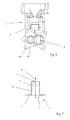
- Figures 1 to 4 and 7 show a piece 1 that is substantially in the form of a sleeve or a tubular fitting, designed to be set into an inlet manifold or splitter 2 made of thermoplastic material, notably with a double plenum or chamber 3, at the level of an inlet opening of this manifold, the said piece 1 having an inlet opening 4 and an outlet opening 4'.
- the piece 1 is characterised in that it is made of a material that withstands temperatures of at least 250°C, has a tubular structure and channels the gaseous flux that passes through it into the said manifold or splitter 2 by directing it substantially towards the centre of the internal volume 3' of the chamber 3.
- the piece 1 is made of a thermosettable material and has a straight or linear tubular structure along its entire length, the inlet and outlet directions of the gases passing through the said piece 1 being combined.
- the piece 1 is made of a thermosettable material and has a substantially linear tubular structure with, at its end 5 that is to be located in the manifold 2 and that has the outlet opening 4', a configuration such that the gaseous flux passing through the said hollow piece 1 is deviated sideways, in relation to the longitudinal direction of extension of the piece 1 and/or to the direction X of flow of the gases therein, before exiting.
- the piece 1 is of sufficient length to bring the gaseous flux to a place that gives directly into the internal volume 3' (flared part of the inlet opening or passage giving into the volume 3').
- the end 5 designed to be located in the manifold 2 is shaped so that, after positioning the said piece 1 in the manifold 2, the incoming gaseous flux is deviated towards the internal volume 3' of the said chamber 3 and the main direction X of flow of the gaseous flux, inside the hollow piece 1 which is substantially linear and/or near the outlet opening 4' or end giving into the corresponding chamber 3, only intersects the wall 2' of the manifold 2 after it has intersected the wall 1' of the piece 1.
- the piece 1 protects the wall 2' of the manifold 2 from a direct impact of the incoming flux of hot EGR gases and directs said flux into the space of the internal volume 3' of the chamber 3 where the gases spread out by diffusing, without leading to a marked pressure drop and allowing the said gases to be sufficiently cooled before they make contact with the wall 2.
- the end 5 to be located in the manifold 2 comprises a portion of wall 6, curved in a circular or elliptical arc, forming an outlet deflector for the gaseous flux passing through the piece 1 and in that the outlet opening 4', corresponding to the end opening giving into the corresponding chamber 3 of the manifold 2 after inserting the piece 1 therein, is positioned sideways in relation to the longitudinal direction DL of extension of the said substantially linear piece 1.
- the curved portion of wall 6, which may have an increased and/or variable thickness, has an angular extension of about 90°, the gaseous flow being substantially deviated by an angle of the same amplitude between its entry into and exit from the piece 1.
- the thickness of the wall 1' of the piece 1 may be optimised in order to adapt it to the thermal and mechanical stresses resulting from the hot gaseous flux, for example by simulation or experimentation.
- the thickness of the portion of inflected or curved wall, subjected to the impact of the flux may be greater than that of the tubular part 7'.
- this portion of wall 6, its edge and its area of connection with part 7' may be defined so as to obtain a flow of a set nature, direction and pressure drop.
- edges defining the inlet 4 and outlet 4' openings of the said piece 1 deviating the gaseous flux passing through it lie in planes that are substantially perpendicular to each other.
- the piece 1 has, in the two above-mentioned embodiments, at the level of and around its inlet opening 4, a connection interface 7, in the form of a plate or fixing flange for example, preferably made in a one piece with the tubular part 7' of the piece 1.
- connection interface 7 has a structure in the form of a cut-out plate designed to form a thermal decoupling element, and may connect, in addition to the first opening corresponding to the inlet opening 4 of the tubular part 7' of the piece 1, also a second opening 8 for the passage of a gaseous flux towards a second chamber, the said tubular part 7' possibly comprising external projecting formations providing supporting and keying surfaces, lines or points cooperating with the reception site of the said piece 1 in the manifold 2.
- the second opening 8 of the plate-shaped connection interface 7 may also extend as a tubular body extending into a second inlet opening of the chamber 3 or into the inlet opening of a second chamber of the said manifold 2.
- the resulting simple construction of the piece 1 means that it is easy to manufacture by injection moulding in a single piece.
- the piece 1 may, for example, be made of Thermodur (a material produced by the Vyncolit Company, Reference X70/10) or PPS (produced by the Ryton Company, Reference R4 220 40% GF), which also have heat insulation properties.
- Thermodur a material produced by the Vyncolit Company, Reference X70/10
- PPS produced by the Ryton Company, Reference R4 220 40% GF
- This invention also relates, as shown in Figures 5 , 6 and 8 , in conjunction with Figures 1 to 4 and 7 , an inlet manifold or splitter for a vehicle with an internal combustion engine, having at least one chamber or plenum, at least one external air inlet opening and at least one inlet opening for exhaust gas to be re-injected or EGR gas, the outside air and EGR gases ending up in the same chamber or in two chambers or parts of separate chambers.
- this manifold 2 has at the level of its EGR gas inlet opening 9 a set-in piece 1 as described above and shown in Figures 1 to 4 and 7 .
- the EGR gas inlet opening 9 consists of or extends as a tubular portion 9' giving into the internal volume 3' of the chamber 3 or corresponding chamber and providing a reception site with a key for the set-in piece 1, such that the gaseous flux exiting therefrom is substantially pointing towards the middle of the said internal volume 3' of the said chamber 3.
- the piece 1 in addition to the deviation of the gaseous flux towards the internal volume 3' of the chamber 3, the piece 1 also forms a protective lining for the wall 2' at the EGR gas inlet passage in the manifold 2.
- the piece 1 In order to achieve a rigid, precise and strong connection between the piece 1 and the manifold 2, the latter, on the external side of the reception site for the set-in piece, has fixing sites 10 and a support surface 10' for the plate or connecting flange 7 forming part of the said piece 1.
- the manifold 2 may have two chambers or plenums and in that the set-in piece 1 is a set-in piece 1 according to the variation not shown or shown in the above-described Figure 2 .
Landscapes
- Engineering & Computer Science (AREA)
- Chemical & Material Sciences (AREA)
- Combustion & Propulsion (AREA)
- Mechanical Engineering (AREA)
- General Engineering & Computer Science (AREA)
- Exhaust-Gas Circulating Devices (AREA)
- Rigid Pipes And Flexible Pipes (AREA)
Abstract
A piece that is substantially in the form of a sleeve or a tubular fitting, designed to be set into an inlet manifold or splitter made of thermoplastic material, notably with a double plenum or chamber, at the level of an inlet opening of this manifold, the said piece having an inlet opening and an outlet opening; the piece (1) is made of a material that withstands temperatures of at least 250°C, has a tubular structure and channels the gas flux that passes through it into the said manifold or splitter by directing it substantially towards the centre of the internal volume of the chamber.
Description
- This invention relates to the field of equipment for vehicles fitted with internal combustion engines, more particularly the inlet manifolds or splitters thereof, and its subject-matter concerns a piece, particularly an inlet and thermal protection piece, designed to be set into such a manifold and a manifold comprising such a piece.
- The recirculation of exhaust gases or EGR gases has now become commonplace, due to the growing importance of economic and ecological considerations connected with using a vehicle that operates by means of a fossil fuel.
- On the other hand, the use of thermoplastic materials in the manufacture of inlet manifolds or splitters is also widespread, this is chiefly for reasons of production costs, weight and versatility of configuration possibilities.
- However, the thermoplastic materials currently used have much lower melting point temperatures than the temperatures of the exhaust gases to be recycled by reinjection into the manifolds or splitters.
- In order to overcome this obvious incompatibility, various devices for cooling, thermo-decoupling or suchlike have already been proposed.
- Nevertheless, these known devices have one or several of the following drawbacks: complex structure, high production cost, large dimensions, heavy weight and too high a pressure drop.
- The aim of this invention is to suggest a solution that has none of these drawbacks.
- For this purpose, its object is a piece substantially in the form of a sleeve or tubular fitting, designed to be set into an inlet manifold or splitter made of a thermoplastic material, at an inlet opening of this manifold, the said piece having an inlet opening and an outlet opening, a piece characterised in that it is made of a thermosettable material, having a substantially linear structure and, at its end that is to be located in the manifold and that has an outlet opening, having a configuration such that the gaseous flux passing through the said hollow piece is deviated sideways, in relation to the longitudinal direction of extension of the piece and/or to the direction of flow of the gases therein, before exiting.
- Further features and advantages of the invention will emerge from the following description of a preferred embodiment, given by way of a non-limiting example and shown in the accompanying drawings, in which:
-
Figures 1, 2 and3 are front-elevation, side-elevation and bird's eye views respectively of a piece according to an embodiment of the invention; -
Figure 4 is a cross-sectional view along A-A of the piece shown inFigure 1 ; -
Figure 5 is a cross-sectional view of an embodiment of an inlet manifold having a reception site for the piece shown inFigures 1 to 4 ; -
Figure 6 is a side elevation along direction B of the manifold shown inFigure 5 ; -
Figure 7 is a cross-sectional view of a piece according to another embodiment of the invention, and -
Figure 8 is a cross-sectional view, similar toFigure 5 , of another embodiment of a manifold fitted with a piece as shown inFigure 7 . -
Figures 1 to 4 and7 show apiece 1 that is substantially in the form of a sleeve or a tubular fitting, designed to be set into an inlet manifold orsplitter 2 made of thermoplastic material, notably with a double plenum orchamber 3, at the level of an inlet opening of this manifold, thesaid piece 1 having an inlet opening 4 and an outlet opening 4'. - According to the invention, the
piece 1 is characterised in that it is made of a material that withstands temperatures of at least 250°C, has a tubular structure and channels the gaseous flux that passes through it into the said manifold orsplitter 2 by directing it substantially towards the centre of the internal volume 3' of thechamber 3. - According to a first embodiment, shown in
Figures 7 and8 , thepiece 1 is made of a thermosettable material and has a straight or linear tubular structure along its entire length, the inlet and outlet directions of the gases passing through thesaid piece 1 being combined. - According to a second embodiment, shown in
Figures 1 to 4 , thepiece 1 is made of a thermosettable material and has a substantially linear tubular structure with, at itsend 5 that is to be located in themanifold 2 and that has the outlet opening 4', a configuration such that the gaseous flux passing through the saidhollow piece 1 is deviated sideways, in relation to the longitudinal direction of extension of thepiece 1 and/or to the direction X of flow of the gases therein, before exiting. - In the two embodiments, the
piece 1 is of sufficient length to bring the gaseous flux to a place that gives directly into the internal volume 3' (flared part of the inlet opening or passage giving into the volume 3'). - More precisely, in the second embodiment, the
end 5 designed to be located in themanifold 2 is shaped so that, after positioning thesaid piece 1 in themanifold 2, the incoming gaseous flux is deviated towards the internal volume 3' of thesaid chamber 3 and the main direction X of flow of the gaseous flux, inside thehollow piece 1 which is substantially linear and/or near the outlet opening 4' or end giving into thecorresponding chamber 3, only intersects the wall 2' of themanifold 2 after it has intersected the wall 1' of thepiece 1. - Thus, the
piece 1 protects the wall 2' of themanifold 2 from a direct impact of the incoming flux of hot EGR gases and directs said flux into the space of the internal volume 3' of thechamber 3 where the gases spread out by diffusing, without leading to a marked pressure drop and allowing the said gases to be sufficiently cooled before they make contact with thewall 2. - According to a preferred embodiment of the invention, shown in
Figures 1 to 4 , theend 5 to be located in themanifold 2 comprises a portion ofwall 6, curved in a circular or elliptical arc, forming an outlet deflector for the gaseous flux passing through thepiece 1 and in that the outlet opening 4', corresponding to the end opening giving into thecorresponding chamber 3 of themanifold 2 after inserting thepiece 1 therein, is positioned sideways in relation to the longitudinal direction DL of extension of the said substantiallylinear piece 1. - Advantageously, the curved portion of
wall 6, which may have an increased and/or variable thickness, has an angular extension of about 90°, the gaseous flow being substantially deviated by an angle of the same amplitude between its entry into and exit from thepiece 1. - The thickness of the wall 1' of the
piece 1 may be optimised in order to adapt it to the thermal and mechanical stresses resulting from the hot gaseous flux, for example by simulation or experimentation. - In particular, the thickness of the portion of inflected or curved wall, subjected to the impact of the flux, may be greater than that of the tubular part 7'.
- Furthermore, the shape of this portion of
wall 6, its edge and its area of connection with part 7' may be defined so as to obtain a flow of a set nature, direction and pressure drop. - According to an advantageous practical variation, the edges defining the
inlet 4 and outlet 4' openings of thesaid piece 1 deviating the gaseous flux passing through it, lie in planes that are substantially perpendicular to each other. - In order to fit it, for example by screwing (preferred mode), gluing, welding or suchlike, the
piece 1 has, in the two above-mentioned embodiments, at the level of and around its inlet opening 4, aconnection interface 7, in the form of a plate or fixing flange for example, preferably made in a one piece with the tubular part 7' of thepiece 1. - Preferably, as shown in
Figures 1 to 4 and7 , theconnection interface 7 has a structure in the form of a cut-out plate designed to form a thermal decoupling element, and may connect, in addition to the first opening corresponding to theinlet opening 4 of the tubular part 7' of thepiece 1, also asecond opening 8 for the passage of a gaseous flux towards a second chamber, the said tubular part 7' possibly comprising external projecting formations providing supporting and keying surfaces, lines or points cooperating with the reception site of the saidpiece 1 in themanifold 2. - According to a variant not shown, the
second opening 8 of the plate-shaped connection interface 7 may also extend as a tubular body extending into a second inlet opening of thechamber 3 or into the inlet opening of a second chamber of the saidmanifold 2. - The resulting simple construction of the
piece 1 means that it is easy to manufacture by injection moulding in a single piece. - The
piece 1 may, for example, be made of Thermodur (a material produced by the Vyncolit Company, Reference X70/10) or PPS (produced by the Ryton Company, Reference R4 220 40% GF), which also have heat insulation properties. - This invention also relates, as shown in
Figures 5 ,6 and8 , in conjunction withFigures 1 to 4 and7 , an inlet manifold or splitter for a vehicle with an internal combustion engine, having at least one chamber or plenum, at least one external air inlet opening and at least one inlet opening for exhaust gas to be re-injected or EGR gas, the outside air and EGR gases ending up in the same chamber or in two chambers or parts of separate chambers. - Specifically, this
manifold 2 has at the level of its EGR gas inlet opening 9 a set-inpiece 1 as described above and shown inFigures 1 to 4 and7 . - Preferably, the EGR
gas inlet opening 9 consists of or extends as a tubular portion 9' giving into the internal volume 3' of thechamber 3 or corresponding chamber and providing a reception site with a key for the set-inpiece 1, such that the gaseous flux exiting therefrom is substantially pointing towards the middle of the said internal volume 3' of thesaid chamber 3. - Thus, in addition to the deviation of the gaseous flux towards the internal volume 3' of the
chamber 3, thepiece 1 also forms a protective lining for the wall 2' at the EGR gas inlet passage in themanifold 2. - In order to achieve a rigid, precise and strong connection between the
piece 1 and themanifold 2, the latter, on the external side of the reception site for the set-in piece, has fixingsites 10 and a support surface 10' for the plate or connectingflange 7 forming part of thesaid piece 1. - According to an advantageous embodiment, the
manifold 2 may have two chambers or plenums and in that the set-inpiece 1 is a set-inpiece 1 according to the variation not shown or shown in the above-describedFigure 2 . - Clearly, the invention is not limited to the embodiment described and shown in the accompanying drawings. Modifications can be made, particularly as regards the construction of the various elements or by substituting equivalent techniques, without departing from the scope of protection of the invention.
Claims (14)
- Piece that is substantially in the form of a sleeve or a tubular fitting, designed to be set into an inlet manifold or splitter made of thermoplastic material, at the level of an inlet opening of this manifold, the said piece having an inlet opening and an outlet opening, piece (1) characterised in that it is made of a material that withstands temperatures of at least 250°C, has a tubular structure and channels the gaseous flux that passes through it into the said manifold or splitter (2) by directing it substantially towards the centre of the internal volume (3') of the chamber (3).
- Piece according to claim 1, characterised in that it is made of a thermosettable material and has a substantially linear tubular structure with, at its end (5) that is to be located in the manifold (2) and that has the outlet opening (4'), a configuration such that the gaseous flux passing through the said hollow piece (1) is deviated sideways, in relation to the longitudinal direction of extension of the piece (1) and/or to the direction (X) of flow of the gases therein, before exiting.
- Piece according to claim 2, characterised in that the end (5) designed to be located in the manifold (2) is shaped so that, after positioning the said piece (1), the incoming gaseous flux is deviated towards the internal volume (3') of the said chamber (3) and the main direction (X) of flow of the gaseous flux, inside the hollow piece (1) which is substantially linear and/or near the outlet opening (4') or end giving into the corresponding chamber (3), only intersects the wall (2') of the manifold (2) after it has intersected the wall (1') of the piece (1).
- Piece according to any one of claims 2 and 3, characterised in that the end (5) to be located in the manifold (2) has a portion of wall (6), curved in a circular or elliptical arc, forming an outlet deflector for the gaseous flux passing through the piece (1) and in that the outlet opening (4'), corresponding to the end-opening giving into the corresponding chamber (3) of the manifold (2) after inserting the piece (1) therein, is positioned sideways in relation to the longitudinal direction (DL) of extension of the said substantially linear piece (1).
- Piece according to claim 4, characterised in that the curved portion of wall (6), which may have an increased and/or variable thickness, has an angular extension of about 90°, the gaseous flow being substantially deviated by an angle of the same amplitude between its entry into and exit from the piece (1).
- Piece according to any one of claims 2 to 5, characterised in that the edges defining the inlet (4) and outlet (4') openings of the said piece (1) deviating the gaseous flux passing through it, lie in planes that are substantially perpendicular to each other.
- Piece according to claim 1, characterised in that it is made of a thermosettable material and has a straight or linear tubular structure along its entire length, the inlet and outlet directions of the gases passing through the said piece (1) being combined.
- Piece according to any one of claims 1 to 7, characterised in that it has, at the level of and around its inlet opening (4), a connection interface (7), in the form of a plate or fixing flange for example, preferably made in a one piece with the tubular part (7') of the piece (1).
- Piece according to claim 8, characterised in that the connection interface (7) has a structure in the form of a cut-out plate designed to form a thermal decoupling element, and may connect, in addition to the first opening corresponding to the inlet opening (4) of the tubular part (7') of the piece (1), also a second opening (8) for the passage of a gaseous flux towards a second chamber, the said tubular part (7') possibly comprising external projecting formations providing supporting and keying surfaces, lines or points cooperating with the reception site of the said piece (1) in the manifold (2).
- Piece according to claim 9, characterised in that the second opening (8) of the plate-shaped connection interface (7) may also extend as a tubular body extending into a second inlet opening of the chamber (3) or into the inlet opening of a second chamber of the said manifold (2).
- Inlet manifold or splitter for a vehicle with an internal combustion engine, having at least one chamber or plenum, at least one external air inlet opening and at least one inlet opening for exhaust gas to be re-injected or EGR gas, the outside air and EGR gases ending up in the same chamber or in two chambers or parts of separate chambers, manifold (2) characterised in that it has at the level of its EGR gas inlet opening (9) a set-in piece (1) according to any of claims 1 to 9.
- Manifold according to claim 11, characterised in that the EGR gas inlet opening (9) consists of or extends as a tubular portion (9') giving into the internal volume (3') of the chamber (3) or corresponding chamber and providing a reception site with a key for the set-in piece (1), such that the gaseous flux exiting therefrom is substantially pointing towards the middle of the said internal volume (3') of the said chamber (3).
- Manifold according to claim 12, characterised in that on the external side of the reception site for the set-in piece, it has fixing sites (10) and a support surface (10') for the plate or connecting flange (7) forming part of the said piece (1).
- Manifold according to any one of claims 11 to 13, characterised in that it has two chambers or plenums and in that the set-in piece (1) is a piece according to any one of claims 9 and 10.
Applications Claiming Priority (1)
| Application Number | Priority Date | Filing Date | Title |
|---|---|---|---|
| FR0755484A FR2917134A1 (en) | 2007-06-05 | 2007-06-05 | THERMAL PROTECTION PIECE AND ADMISSION MANIFOLD HAVING SUCH A PART. |
Publications (1)
| Publication Number | Publication Date |
|---|---|
| EP2000660A1 true EP2000660A1 (en) | 2008-12-10 |
Family
ID=38941910
Family Applications (1)
| Application Number | Title | Priority Date | Filing Date |
|---|---|---|---|
| EP08157589A Withdrawn EP2000660A1 (en) | 2007-06-05 | 2008-06-04 | Thermal protection piece and inlet manifold comprising such a piece |
Country Status (2)
| Country | Link |
|---|---|
| EP (1) | EP2000660A1 (en) |
| FR (1) | FR2917134A1 (en) |
Citations (6)
| Publication number | Priority date | Publication date | Assignee | Title |
|---|---|---|---|---|
| JPH11210576A (en) * | 1998-01-30 | 1999-08-03 | Mazda Motor Corp | Engine intake system |
| JP2000054915A (en) * | 1998-08-10 | 2000-02-22 | Isuzu Motors Ltd | EGR device |
| US6173701B1 (en) * | 1996-09-18 | 2001-01-16 | Nissan Motor Co., Ltd. | Exhaust gas recirculation system of internal combustion engine |
| JP2001234815A (en) * | 2000-02-24 | 2001-08-31 | Nissan Motor Co Ltd | Exhaust gas recirculation system for internal combustion engine |
| DE10202612A1 (en) * | 2002-01-24 | 2003-07-31 | Pierburg Gmbh | Exhaust gas feedback device for air induction pipe section has exhaust return valve housing in one piece with valve outlet pipe, exhaust return device mounted with induction pipe section |
| FR2879262A1 (en) * | 2004-12-13 | 2006-06-16 | Renault Sas | PLASTIC AIR DISTRIBUTOR FOR INTERNAL COMBUSTION ENGINE WITH RECIRCULATION OF EXHAUST GASES. |
-
2007
- 2007-06-05 FR FR0755484A patent/FR2917134A1/en active Pending
-
2008
- 2008-06-04 EP EP08157589A patent/EP2000660A1/en not_active Withdrawn
Patent Citations (6)
| Publication number | Priority date | Publication date | Assignee | Title |
|---|---|---|---|---|
| US6173701B1 (en) * | 1996-09-18 | 2001-01-16 | Nissan Motor Co., Ltd. | Exhaust gas recirculation system of internal combustion engine |
| JPH11210576A (en) * | 1998-01-30 | 1999-08-03 | Mazda Motor Corp | Engine intake system |
| JP2000054915A (en) * | 1998-08-10 | 2000-02-22 | Isuzu Motors Ltd | EGR device |
| JP2001234815A (en) * | 2000-02-24 | 2001-08-31 | Nissan Motor Co Ltd | Exhaust gas recirculation system for internal combustion engine |
| DE10202612A1 (en) * | 2002-01-24 | 2003-07-31 | Pierburg Gmbh | Exhaust gas feedback device for air induction pipe section has exhaust return valve housing in one piece with valve outlet pipe, exhaust return device mounted with induction pipe section |
| FR2879262A1 (en) * | 2004-12-13 | 2006-06-16 | Renault Sas | PLASTIC AIR DISTRIBUTOR FOR INTERNAL COMBUSTION ENGINE WITH RECIRCULATION OF EXHAUST GASES. |
Also Published As
| Publication number | Publication date |
|---|---|
| FR2917134A1 (en) | 2008-12-12 |
Similar Documents
| Publication | Publication Date | Title |
|---|---|---|
| CN102959205B (en) | Insert the heat exchange structure in turbine engine exhaust device | |
| US9726071B2 (en) | Multi-stage turbocharged engine | |
| US8899214B2 (en) | Exhaust gas recirculation device for an internal combustion engine | |
| US20170260888A1 (en) | Mixer | |
| US8206476B2 (en) | Cover for a diesel particulate filter | |
| EP2216599A3 (en) | Premixed direct injection nozzle | |
| RU2007115878A (en) | EXHAUST MANIFOLD FOR WORKING GASES FORMING THE ELBOW, IN THE AIRCRAFT, METHOD FOR CARRYING OUT THE WORK OF THE EXHAUST MANIFOLD AND A GAS TURBINE ENGINE CONTAINING A LARGE EXTENDED | |
| US20140345282A1 (en) | Combustion chamber for a gas turbine plant | |
| JP4965513B2 (en) | Intake manifold | |
| US8341952B2 (en) | Exhaust manifold | |
| US8104273B2 (en) | Double-shell manifold | |
| CN103608577A (en) | Intake housing including a heat exchanger | |
| US9500120B2 (en) | Integration ring | |
| CN102444461B (en) | Combustion chamber charge device | |
| US9228488B2 (en) | High pressure turbine inlet duct and engine | |
| EP2000660A1 (en) | Thermal protection piece and inlet manifold comprising such a piece | |
| US20120102910A1 (en) | High Flow Eductor | |
| US6959700B2 (en) | Flow deflector for a pipe | |
| US20180299128A1 (en) | Fuel nozzle assembly and gas turbine having the same | |
| US7614379B2 (en) | Air horn for efficient fluid intake | |
| CN108758689B (en) | Combustion chamber of miniature turbine engine | |
| US20160115873A1 (en) | Igniter assembly | |
| KR101137820B1 (en) | Intake manifold having the heat protector | |
| US11867401B2 (en) | Pre-vaporizing pipe, combustion assembly provided therewith and turbomachine provided therewith | |
| CA2693527C (en) | Nozzle design to reduce fretting |
Legal Events
| Date | Code | Title | Description |
|---|---|---|---|
| PUAI | Public reference made under article 153(3) epc to a published international application that has entered the european phase |
Free format text: ORIGINAL CODE: 0009012 |
|
| AK | Designated contracting states |
Kind code of ref document: A1 Designated state(s): AT BE BG CH CY CZ DE DK EE ES FI FR GB GR HR HU IE IS IT LI LT LU LV MC MT NL NO PL PT RO SE SI SK TR |
|
| AX | Request for extension of the european patent |
Extension state: AL BA MK RS |
|
| AKX | Designation fees paid | ||
| REG | Reference to a national code |
Ref country code: DE Ref legal event code: 8566 |
|
| STAA | Information on the status of an ep patent application or granted ep patent |
Free format text: STATUS: THE APPLICATION IS DEEMED TO BE WITHDRAWN |
|
| 18D | Application deemed to be withdrawn |
Effective date: 20090611 |