EP2000639A1 - Method of purifying exhaust gas from internal combustion engine - Google Patents
Method of purifying exhaust gas from internal combustion engine Download PDFInfo
- Publication number
- EP2000639A1 EP2000639A1 EP07739514A EP07739514A EP2000639A1 EP 2000639 A1 EP2000639 A1 EP 2000639A1 EP 07739514 A EP07739514 A EP 07739514A EP 07739514 A EP07739514 A EP 07739514A EP 2000639 A1 EP2000639 A1 EP 2000639A1
- Authority
- EP
- European Patent Office
- Prior art keywords
- catalyst
- exhaust gas
- hydrocarbon
- temperature
- increasing temperature
- Prior art date
- Legal status (The legal status is an assumption and is not a legal conclusion. Google has not performed a legal analysis and makes no representation as to the accuracy of the status listed.)
- Granted
Links
Images
Classifications
-
- F—MECHANICAL ENGINEERING; LIGHTING; HEATING; WEAPONS; BLASTING
- F01—MACHINES OR ENGINES IN GENERAL; ENGINE PLANTS IN GENERAL; STEAM ENGINES
- F01N—GAS-FLOW SILENCERS OR EXHAUST APPARATUS FOR MACHINES OR ENGINES IN GENERAL; GAS-FLOW SILENCERS OR EXHAUST APPARATUS FOR INTERNAL COMBUSTION ENGINES
- F01N3/00—Exhaust or silencing apparatus having means for purifying, rendering innocuous, or otherwise treating exhaust
- F01N3/02—Exhaust or silencing apparatus having means for purifying, rendering innocuous, or otherwise treating exhaust for cooling, or for removing solid constituents of, exhaust
-
- B—PERFORMING OPERATIONS; TRANSPORTING
- B01—PHYSICAL OR CHEMICAL PROCESSES OR APPARATUS IN GENERAL
- B01D—SEPARATION
- B01D53/00—Separation of gases or vapours; Recovering vapours of volatile solvents from gases; Chemical or biological purification of waste gases, e.g. engine exhaust gases, smoke, fumes, flue gases, aerosols
- B01D53/34—Chemical or biological purification of waste gases
- B01D53/92—Chemical or biological purification of waste gases of engine exhaust gases
- B01D53/94—Chemical or biological purification of waste gases of engine exhaust gases by catalytic processes
- B01D53/9459—Removing one or more of nitrogen oxides, carbon monoxide, or hydrocarbons by multiple successive catalytic functions; systems with more than one different function, e.g. zone coated catalysts
- B01D53/9463—Removing one or more of nitrogen oxides, carbon monoxide, or hydrocarbons by multiple successive catalytic functions; systems with more than one different function, e.g. zone coated catalysts with catalysts positioned on one brick
- B01D53/9472—Removing one or more of nitrogen oxides, carbon monoxide, or hydrocarbons by multiple successive catalytic functions; systems with more than one different function, e.g. zone coated catalysts with catalysts positioned on one brick in different zones
-
- B—PERFORMING OPERATIONS; TRANSPORTING
- B01—PHYSICAL OR CHEMICAL PROCESSES OR APPARATUS IN GENERAL
- B01D—SEPARATION
- B01D53/00—Separation of gases or vapours; Recovering vapours of volatile solvents from gases; Chemical or biological purification of waste gases, e.g. engine exhaust gases, smoke, fumes, flue gases, aerosols
- B01D53/34—Chemical or biological purification of waste gases
- B01D53/92—Chemical or biological purification of waste gases of engine exhaust gases
- B01D53/94—Chemical or biological purification of waste gases of engine exhaust gases by catalytic processes
-
- B—PERFORMING OPERATIONS; TRANSPORTING
- B01—PHYSICAL OR CHEMICAL PROCESSES OR APPARATUS IN GENERAL
- B01J—CHEMICAL OR PHYSICAL PROCESSES, e.g. CATALYSIS OR COLLOID CHEMISTRY; THEIR RELEVANT APPARATUS
- B01J23/00—Catalysts comprising metals or metal oxides or hydroxides, not provided for in group B01J21/00
- B01J23/38—Catalysts comprising metals or metal oxides or hydroxides, not provided for in group B01J21/00 of noble metals
- B01J23/54—Catalysts comprising metals or metal oxides or hydroxides, not provided for in group B01J21/00 of noble metals combined with metals, oxides or hydroxides provided for in groups B01J23/02 - B01J23/36
- B01J23/56—Platinum group metals
- B01J23/58—Platinum group metals with alkali- or alkaline earth metals
-
- F—MECHANICAL ENGINEERING; LIGHTING; HEATING; WEAPONS; BLASTING
- F01—MACHINES OR ENGINES IN GENERAL; ENGINE PLANTS IN GENERAL; STEAM ENGINES
- F01N—GAS-FLOW SILENCERS OR EXHAUST APPARATUS FOR MACHINES OR ENGINES IN GENERAL; GAS-FLOW SILENCERS OR EXHAUST APPARATUS FOR INTERNAL COMBUSTION ENGINES
- F01N11/00—Monitoring or diagnostic devices for exhaust-gas treatment apparatus, e.g. for catalytic activity
-
- F—MECHANICAL ENGINEERING; LIGHTING; HEATING; WEAPONS; BLASTING
- F01—MACHINES OR ENGINES IN GENERAL; ENGINE PLANTS IN GENERAL; STEAM ENGINES
- F01N—GAS-FLOW SILENCERS OR EXHAUST APPARATUS FOR MACHINES OR ENGINES IN GENERAL; GAS-FLOW SILENCERS OR EXHAUST APPARATUS FOR INTERNAL COMBUSTION ENGINES
- F01N13/00—Exhaust or silencing apparatus characterised by constructional features ; Exhaust or silencing apparatus, or parts thereof, having pertinent characteristics not provided for in, or of interest apart from, groups F01N1/00 - F01N5/00, F01N9/00, F01N11/00
- F01N13/009—Exhaust or silencing apparatus characterised by constructional features ; Exhaust or silencing apparatus, or parts thereof, having pertinent characteristics not provided for in, or of interest apart from, groups F01N1/00 - F01N5/00, F01N9/00, F01N11/00 having two or more separate purifying devices arranged in series
- F01N13/0097—Exhaust or silencing apparatus characterised by constructional features ; Exhaust or silencing apparatus, or parts thereof, having pertinent characteristics not provided for in, or of interest apart from, groups F01N1/00 - F01N5/00, F01N9/00, F01N11/00 having two or more separate purifying devices arranged in series the purifying devices are arranged in a single housing
-
- F—MECHANICAL ENGINEERING; LIGHTING; HEATING; WEAPONS; BLASTING
- F01—MACHINES OR ENGINES IN GENERAL; ENGINE PLANTS IN GENERAL; STEAM ENGINES
- F01N—GAS-FLOW SILENCERS OR EXHAUST APPARATUS FOR MACHINES OR ENGINES IN GENERAL; GAS-FLOW SILENCERS OR EXHAUST APPARATUS FOR INTERNAL COMBUSTION ENGINES
- F01N3/00—Exhaust or silencing apparatus having means for purifying, rendering innocuous, or otherwise treating exhaust
- F01N3/02—Exhaust or silencing apparatus having means for purifying, rendering innocuous, or otherwise treating exhaust for cooling, or for removing solid constituents of, exhaust
- F01N3/021—Exhaust or silencing apparatus having means for purifying, rendering innocuous, or otherwise treating exhaust for cooling, or for removing solid constituents of, exhaust by means of filters
- F01N3/023—Exhaust or silencing apparatus having means for purifying, rendering innocuous, or otherwise treating exhaust for cooling, or for removing solid constituents of, exhaust by means of filters using means for regenerating the filters, e.g. by burning trapped particles
- F01N3/025—Exhaust or silencing apparatus having means for purifying, rendering innocuous, or otherwise treating exhaust for cooling, or for removing solid constituents of, exhaust by means of filters using means for regenerating the filters, e.g. by burning trapped particles using fuel burner or by adding fuel to exhaust
- F01N3/0253—Exhaust or silencing apparatus having means for purifying, rendering innocuous, or otherwise treating exhaust for cooling, or for removing solid constituents of, exhaust by means of filters using means for regenerating the filters, e.g. by burning trapped particles using fuel burner or by adding fuel to exhaust adding fuel to exhaust gases
-
- F—MECHANICAL ENGINEERING; LIGHTING; HEATING; WEAPONS; BLASTING
- F01—MACHINES OR ENGINES IN GENERAL; ENGINE PLANTS IN GENERAL; STEAM ENGINES
- F01N—GAS-FLOW SILENCERS OR EXHAUST APPARATUS FOR MACHINES OR ENGINES IN GENERAL; GAS-FLOW SILENCERS OR EXHAUST APPARATUS FOR INTERNAL COMBUSTION ENGINES
- F01N3/00—Exhaust or silencing apparatus having means for purifying, rendering innocuous, or otherwise treating exhaust
- F01N3/08—Exhaust or silencing apparatus having means for purifying, rendering innocuous, or otherwise treating exhaust for rendering innocuous
- F01N3/0807—Exhaust or silencing apparatus having means for purifying, rendering innocuous, or otherwise treating exhaust for rendering innocuous by using absorbents or adsorbents
- F01N3/0821—Exhaust or silencing apparatus having means for purifying, rendering innocuous, or otherwise treating exhaust for rendering innocuous by using absorbents or adsorbents combined with particulate filters
-
- F—MECHANICAL ENGINEERING; LIGHTING; HEATING; WEAPONS; BLASTING
- F01—MACHINES OR ENGINES IN GENERAL; ENGINE PLANTS IN GENERAL; STEAM ENGINES
- F01N—GAS-FLOW SILENCERS OR EXHAUST APPARATUS FOR MACHINES OR ENGINES IN GENERAL; GAS-FLOW SILENCERS OR EXHAUST APPARATUS FOR INTERNAL COMBUSTION ENGINES
- F01N3/00—Exhaust or silencing apparatus having means for purifying, rendering innocuous, or otherwise treating exhaust
- F01N3/08—Exhaust or silencing apparatus having means for purifying, rendering innocuous, or otherwise treating exhaust for rendering innocuous
- F01N3/0807—Exhaust or silencing apparatus having means for purifying, rendering innocuous, or otherwise treating exhaust for rendering innocuous by using absorbents or adsorbents
- F01N3/0828—Exhaust or silencing apparatus having means for purifying, rendering innocuous, or otherwise treating exhaust for rendering innocuous by using absorbents or adsorbents characterised by the absorbed or adsorbed substances
- F01N3/0842—Nitrogen oxides
-
- F—MECHANICAL ENGINEERING; LIGHTING; HEATING; WEAPONS; BLASTING
- F01—MACHINES OR ENGINES IN GENERAL; ENGINE PLANTS IN GENERAL; STEAM ENGINES
- F01N—GAS-FLOW SILENCERS OR EXHAUST APPARATUS FOR MACHINES OR ENGINES IN GENERAL; GAS-FLOW SILENCERS OR EXHAUST APPARATUS FOR INTERNAL COMBUSTION ENGINES
- F01N3/00—Exhaust or silencing apparatus having means for purifying, rendering innocuous, or otherwise treating exhaust
- F01N3/08—Exhaust or silencing apparatus having means for purifying, rendering innocuous, or otherwise treating exhaust for rendering innocuous
- F01N3/10—Exhaust or silencing apparatus having means for purifying, rendering innocuous, or otherwise treating exhaust for rendering innocuous by thermal or catalytic conversion of noxious components of exhaust
- F01N3/105—General auxiliary catalysts, e.g. upstream or downstream of the main catalyst
- F01N3/106—Auxiliary oxidation catalysts
-
- F—MECHANICAL ENGINEERING; LIGHTING; HEATING; WEAPONS; BLASTING
- F01—MACHINES OR ENGINES IN GENERAL; ENGINE PLANTS IN GENERAL; STEAM ENGINES
- F01N—GAS-FLOW SILENCERS OR EXHAUST APPARATUS FOR MACHINES OR ENGINES IN GENERAL; GAS-FLOW SILENCERS OR EXHAUST APPARATUS FOR INTERNAL COMBUSTION ENGINES
- F01N3/00—Exhaust or silencing apparatus having means for purifying, rendering innocuous, or otherwise treating exhaust
- F01N3/08—Exhaust or silencing apparatus having means for purifying, rendering innocuous, or otherwise treating exhaust for rendering innocuous
- F01N3/10—Exhaust or silencing apparatus having means for purifying, rendering innocuous, or otherwise treating exhaust for rendering innocuous by thermal or catalytic conversion of noxious components of exhaust
- F01N3/18—Exhaust or silencing apparatus having means for purifying, rendering innocuous, or otherwise treating exhaust for rendering innocuous by thermal or catalytic conversion of noxious components of exhaust characterised by methods of operation; Control
- F01N3/20—Exhaust or silencing apparatus having means for purifying, rendering innocuous, or otherwise treating exhaust for rendering innocuous by thermal or catalytic conversion of noxious components of exhaust characterised by methods of operation; Control specially adapted for catalytic conversion ; Methods of operation or control of catalytic converters
-
- F—MECHANICAL ENGINEERING; LIGHTING; HEATING; WEAPONS; BLASTING
- F01—MACHINES OR ENGINES IN GENERAL; ENGINE PLANTS IN GENERAL; STEAM ENGINES
- F01N—GAS-FLOW SILENCERS OR EXHAUST APPARATUS FOR MACHINES OR ENGINES IN GENERAL; GAS-FLOW SILENCERS OR EXHAUST APPARATUS FOR INTERNAL COMBUSTION ENGINES
- F01N3/00—Exhaust or silencing apparatus having means for purifying, rendering innocuous, or otherwise treating exhaust
- F01N3/08—Exhaust or silencing apparatus having means for purifying, rendering innocuous, or otherwise treating exhaust for rendering innocuous
- F01N3/10—Exhaust or silencing apparatus having means for purifying, rendering innocuous, or otherwise treating exhaust for rendering innocuous by thermal or catalytic conversion of noxious components of exhaust
- F01N3/24—Exhaust or silencing apparatus having means for purifying, rendering innocuous, or otherwise treating exhaust for rendering innocuous by thermal or catalytic conversion of noxious components of exhaust characterised by constructional aspects of converting apparatus
-
- B—PERFORMING OPERATIONS; TRANSPORTING
- B01—PHYSICAL OR CHEMICAL PROCESSES OR APPARATUS IN GENERAL
- B01D—SEPARATION
- B01D2251/00—Reactants
- B01D2251/20—Reductants
- B01D2251/208—Hydrocarbons
-
- B—PERFORMING OPERATIONS; TRANSPORTING
- B01—PHYSICAL OR CHEMICAL PROCESSES OR APPARATUS IN GENERAL
- B01D—SEPARATION
- B01D2255/00—Catalysts
- B01D2255/10—Noble metals or compounds thereof
- B01D2255/102—Platinum group metals
-
- B—PERFORMING OPERATIONS; TRANSPORTING
- B01—PHYSICAL OR CHEMICAL PROCESSES OR APPARATUS IN GENERAL
- B01D—SEPARATION
- B01D2255/00—Catalysts
- B01D2255/20—Metals or compounds thereof
- B01D2255/204—Alkaline earth metals
- B01D2255/2047—Magnesium
-
- B—PERFORMING OPERATIONS; TRANSPORTING
- B01—PHYSICAL OR CHEMICAL PROCESSES OR APPARATUS IN GENERAL
- B01D—SEPARATION
- B01D53/00—Separation of gases or vapours; Recovering vapours of volatile solvents from gases; Chemical or biological purification of waste gases, e.g. engine exhaust gases, smoke, fumes, flue gases, aerosols
- B01D53/34—Chemical or biological purification of waste gases
- B01D53/92—Chemical or biological purification of waste gases of engine exhaust gases
- B01D53/94—Chemical or biological purification of waste gases of engine exhaust gases by catalytic processes
- B01D53/9404—Removing only nitrogen compounds
- B01D53/9409—Nitrogen oxides
- B01D53/9413—Processes characterised by a specific catalyst
- B01D53/9422—Processes characterised by a specific catalyst for removing nitrogen oxides by NOx storage or reduction by cyclic switching between lean and rich exhaust gases (LNT, NSC, NSR)
-
- B—PERFORMING OPERATIONS; TRANSPORTING
- B01—PHYSICAL OR CHEMICAL PROCESSES OR APPARATUS IN GENERAL
- B01D—SEPARATION
- B01D53/00—Separation of gases or vapours; Recovering vapours of volatile solvents from gases; Chemical or biological purification of waste gases, e.g. engine exhaust gases, smoke, fumes, flue gases, aerosols
- B01D53/34—Chemical or biological purification of waste gases
- B01D53/92—Chemical or biological purification of waste gases of engine exhaust gases
- B01D53/94—Chemical or biological purification of waste gases of engine exhaust gases by catalytic processes
- B01D53/9445—Simultaneously removing carbon monoxide, hydrocarbons or nitrogen oxides making use of three-way catalysts [TWC] or four-way-catalysts [FWC]
- B01D53/945—Simultaneously removing carbon monoxide, hydrocarbons or nitrogen oxides making use of three-way catalysts [TWC] or four-way-catalysts [FWC] characterised by a specific catalyst
-
- B—PERFORMING OPERATIONS; TRANSPORTING
- B01—PHYSICAL OR CHEMICAL PROCESSES OR APPARATUS IN GENERAL
- B01J—CHEMICAL OR PHYSICAL PROCESSES, e.g. CATALYSIS OR COLLOID CHEMISTRY; THEIR RELEVANT APPARATUS
- B01J37/00—Processes, in general, for preparing catalysts; Processes, in general, for activation of catalysts
- B01J37/02—Impregnation, coating or precipitation
- B01J37/024—Multiple impregnation or coating
- B01J37/0246—Coatings comprising a zeolite
-
- F—MECHANICAL ENGINEERING; LIGHTING; HEATING; WEAPONS; BLASTING
- F01—MACHINES OR ENGINES IN GENERAL; ENGINE PLANTS IN GENERAL; STEAM ENGINES
- F01N—GAS-FLOW SILENCERS OR EXHAUST APPARATUS FOR MACHINES OR ENGINES IN GENERAL; GAS-FLOW SILENCERS OR EXHAUST APPARATUS FOR INTERNAL COMBUSTION ENGINES
- F01N2560/00—Exhaust systems with means for detecting or measuring exhaust gas components or characteristics
- F01N2560/06—Exhaust systems with means for detecting or measuring exhaust gas components or characteristics the means being a temperature sensor
-
- F—MECHANICAL ENGINEERING; LIGHTING; HEATING; WEAPONS; BLASTING
- F01—MACHINES OR ENGINES IN GENERAL; ENGINE PLANTS IN GENERAL; STEAM ENGINES
- F01N—GAS-FLOW SILENCERS OR EXHAUST APPARATUS FOR MACHINES OR ENGINES IN GENERAL; GAS-FLOW SILENCERS OR EXHAUST APPARATUS FOR INTERNAL COMBUSTION ENGINES
- F01N2560/00—Exhaust systems with means for detecting or measuring exhaust gas components or characteristics
- F01N2560/08—Exhaust systems with means for detecting or measuring exhaust gas components or characteristics the means being a pressure sensor
-
- F—MECHANICAL ENGINEERING; LIGHTING; HEATING; WEAPONS; BLASTING
- F01—MACHINES OR ENGINES IN GENERAL; ENGINE PLANTS IN GENERAL; STEAM ENGINES
- F01N—GAS-FLOW SILENCERS OR EXHAUST APPARATUS FOR MACHINES OR ENGINES IN GENERAL; GAS-FLOW SILENCERS OR EXHAUST APPARATUS FOR INTERNAL COMBUSTION ENGINES
- F01N2560/00—Exhaust systems with means for detecting or measuring exhaust gas components or characteristics
- F01N2560/14—Exhaust systems with means for detecting or measuring exhaust gas components or characteristics having more than one sensor of one kind
-
- Y—GENERAL TAGGING OF NEW TECHNOLOGICAL DEVELOPMENTS; GENERAL TAGGING OF CROSS-SECTIONAL TECHNOLOGIES SPANNING OVER SEVERAL SECTIONS OF THE IPC; TECHNICAL SUBJECTS COVERED BY FORMER USPC CROSS-REFERENCE ART COLLECTIONS [XRACs] AND DIGESTS
- Y02—TECHNOLOGIES OR APPLICATIONS FOR MITIGATION OR ADAPTATION AGAINST CLIMATE CHANGE
- Y02T—CLIMATE CHANGE MITIGATION TECHNOLOGIES RELATED TO TRANSPORTATION
- Y02T10/00—Road transport of goods or passengers
- Y02T10/10—Internal combustion engine [ICE] based vehicles
- Y02T10/12—Improving ICE efficiencies
-
- Y—GENERAL TAGGING OF NEW TECHNOLOGICAL DEVELOPMENTS; GENERAL TAGGING OF CROSS-SECTIONAL TECHNOLOGIES SPANNING OVER SEVERAL SECTIONS OF THE IPC; TECHNICAL SUBJECTS COVERED BY FORMER USPC CROSS-REFERENCE ART COLLECTIONS [XRACs] AND DIGESTS
- Y02—TECHNOLOGIES OR APPLICATIONS FOR MITIGATION OR ADAPTATION AGAINST CLIMATE CHANGE
- Y02T—CLIMATE CHANGE MITIGATION TECHNOLOGIES RELATED TO TRANSPORTATION
- Y02T10/00—Road transport of goods or passengers
- Y02T10/10—Internal combustion engine [ICE] based vehicles
- Y02T10/40—Engine management systems
Definitions
- the present invention relates to a method for purification of exhaust gas from an internal combustion engine, and in more detail the present invention relates to a purification method excellent in removing particulates and the like from exhaust gas from an internal combustion engine such as diesel engine.
- the filter is conventionally regenerated by arranging a heating apparatus such as an electric heater at the filter, to combust and remove PM by heating ( JP-B-2953409 ).
- a purification apparatus for diesel exhaust gas which comprises a filter for trapping diesel engine particulates, a catalyst converter having good activity to hydrocarbon (HC) installed at the upstream side of an exhaust gas pipeline of the filter, and an HC control unit enabling supplying a large quantity of HC to the catalyst converter, and as this catalyst, platinum, palladium or the like has been disclosed ( JP-A-60-043113 ).
- a purification system of exhaust gas from an internal combustion engine which comprises a trapped amount estimation means for estimating trapped amount of a particulate material trapped at the above filter, and a maximal injection amount control means for limiting maximal injection amount of an internal combustion engine, when a particulate material estimated by the trapping amount estimation means becomes predetermined judgment value or higher ( JP-A-2004-108207 ).
- a method described in the above literature has an advantage that production cost is lower and limitation of installment place is mitigated as compared with a method etc. by using an electric heater, however, on the other hand, it has a problem that a large quantity of hydrocarbon supply is required and there is poisoning caused by adhering of hydrocarbon onto a catalyst, because of a large quantity of hydrocarbon supply.
- This hydrocarbon poisoning tends to occur more easily when hydrocarbon is supplied at temperature of a part of a catalyst for increasing temperature not more than boiling point of hydrocarbon supplied, or also in higher concentration of hydrocarbon. It is because, low temperature at a part of the catalyst for increasing temperature delays combustion reaction rate of hydrocarbon, and high concentration of hydrocarbon makes supply rate of hydrocarbon faster than combustion treatment rate of a catalyst for increasing temperature.
- a conventional method required a control to supply hydrocarbon, after temperature increase up to temperature at which combustion rate of hydrocarbon becomes fast, by control of an engine side, or supply a small quantity enabling sufficient combustion of hydrocarbon.
- control lengthens regeneration time, resulting in adverse effect on running performance or environment. Accordingly, more rapid temperature increasing performance has been required, and in order to attain this, it is a problem to enhance combustion characteristics and temperature increasing performances for high concentration hydrocarbon at low temperature.
- the present invention is one having the above constitution, and in particular, a system for supplying high concentration hydrocarbon, enabling stable increase in exhaust gas temperature, even when exhaust gas temperature is low, by using a catalyst containing, as a catalyst for increasing temperature, a catalytically active component (A) consisting of (a) platinum, (b) an oxide of at least one metal selected from the group consisting of magnesium, an alkaline earth metal and an alkali metal, and (c) at least one noble metal selected from the group consisting of palladium and rhodium.
- A catalytically active component
- the effect becomes significant by presence of platinum, and an oxide of magnesium and/or an alkaline earth metal and/or an alkali metal in suitable ratio.
- high concentration hydrocarbon can be introduced even when exhaust gas temperature is low, and thus exhaust gas temperature can be increased rapidly, the effect is significant.
- magnesium and/or an alkaline earth metal and/or an alkali metal have electron donating property, and co-presence with platinum can activate platinum particle surface, and enhance combustion performance for high concentration hydrocarbon.
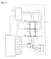
- FIG. 1 is one showing schematic drawing of a purification apparatus of exhaust gas from an internal combustion engine, according to the present invention.
- a temperature increasing region 5 filled with the catalyst for increasing temperature, and a filtering region 6 installed with , if necessary, the diesel particulate filter in communication to the downstream side thereof are installed by further communication thereto.
- a fuel supply nozzle 4 installed with a check valve or the like (not shown), if necessary, and a fuel supply pump 3 communicating to the nozzle 4, as supply means of hydrocarbon-based liquid fuel for temperature increase. That is, in Fig. 1 , a hydrocarbon supply apparatus is the fuel supply pump 3 and the fuel supply nozzle 4.
- a signal of each of the temperature sensors and the pressure sensors is connected so as to enter a controller 9, as well as a signal of the controller 9 is connected so as to enter a pump.
- hydrocarbon-based liquid for example, fuel
- hydrocarbon-based liquid for example, fuel
- a cylinder of an internal combustion engine 1 for example, a diesel engine
- hydrocarbon-based liquid for example, fuel
- hydrocarbon-based liquid maybe supplied after completion of combustion and before completion of an exhaustion step of fuel inside the cylinder of the internal combustion engine.
- exhaust gas of the internal combustion engine 1 passes through the exhaustion pipe 2 and at the temperature increasing region 5 filled with the catalyst for increasing temperature, where high concentrated unreacted hydrocarbon (HC) contained in the exhaust gas is combusted, and is converted to water or carbon dioxide, which is exhausted outside via the filtering region 6 filled with the filter, or via a muffler (not shown).
- HC high concentrated unreacted hydrocarbon
- particulates contained in exhaust gas are trapped into a particulate filter at the filtering region 6, however, because they are gradually accumulated, pressure onto the filter increases, and at the time when the pressure value reaches predetermined certain value and filter temperature reaches predetermined certain temperature, hydrocarbon-based liquid fuel is injected from the nozzle 4, and is supplied onto the catalyst for increasing temperature 5 of the temperature increasing region 5.
- the pressure sensor 11 installed between the temperature increasing region 5 and the filtering region 6, is designed to measure pressure of the filtering region 6, when the measurement value becomes equal to or higher than predetermined pressure, the fuel supply pump 3 is operated by direction of the controller 9, based on value received, while action of the pump 3 is stopped by direction of the controller 9, when the measurement value becomes equal to or lower than predetermined pressure.
- the pressure sensor 10 at the entrance of temperature increasing region 5 is installed, in the case where the pressure sensor 11 is not installed between the temperature increasing region 5 and the filtering region 6, and designed to detect pressure loaded at the temperature increasing region 5 and a filtering region, and measures pressure loaded at the catalyst for increasing temperature and the filtering region by difference between the pressure sensor 10 and the pressure sensor 12.
- a fuel supply signal is sent to a fuel injection apparatus to start filter regeneration control (fuel supply), in general, when temperature and pressure information in front of and at the back of the filter (or inside the filter) is sent to the control unit, after measurement of pressure loaded at the filter, and in the case where the value is over a certain value. Also during fuel supply, pressure value of the filter is sent to the control unit, by the pressure sensor, and at the time when the pressure value decreases down to a certain value, the regeneration control is stopped.
- filter regeneration control fuel supply
- hydrocarbon any one may be used as long as it is hydrocarbon enabling to generate heat by fuel, and includes methane, ethane, propane, gasoline, methanol, ethanol, dimethyl ether, light oil or the like, and preferably light oil.
- Use amount thereof is from 1,000 to 40,000 ppm by volume, preferably from 5,000 to 30,000 ppm by volume, still more preferably from 5,000 to 20,000 ppm by volume, and most preferably from 5,000 to 15,000 ppm by volume, as converted to methane, relative to the exhaust gas.
- an introduction place of hydrocarbon may be any place at the upstream of the catalyst for increasing temperature, but preferably at the upstream of the catalyst for increasing temperature, after combustion of an engine.
- "after combustion of an engine” may be the downstream of exhausted gas from the engine, or may be inside the engine.
- introduction temperature of hydrocarbon is from 200°C to 600°C, preferably from 200°C to 350°C, and still more preferably from 200°C to 300°C.
- the catalyst for increasing temperature to be used in the present invention is obtained by supporting a catalytically active component (A) consisting of (a) platinum, (b) an oxide of at least one metal selected from the group consisting of magnesium, an alkaline earth metal and an alkali metal, and (c) at least one noble metal selected from palladium and rhodium, on refractory inorganic oxide powders (B), and coating the inorganic oxide powder having the catalytically active component supported thereon, onto a refractory three-dimensional structure body.
- a catalytically active component consisting of (a) platinum, (b) an oxide of at least one metal selected from the group consisting of magnesium, an alkaline earth metal and an alkali metal, and (c) at least one noble metal selected from palladium and rhodium
- Essential a catalytically active component to be used in the present invention are platinum, an oxide of magnesium and/or an alkaline earth metal and/or an alkali metal, and palladium and/or rhodium.
- a metal form is more preferable than an oxide
- an oxide form is more preferable than a metal.
- Use amount of platinum, palladium and/or rhodium (in total) is usually from 0.1 to 20 g, and preferably from 0.5 to 10 g, per 1 L of a refractory three-dimensional structure body. The use amount below 0.1 g provides insufficient catalytic activity at the initial stage and after long period of use, on the other hand, the use amount over 20 g does not provide catalytic activity proportional to the use amount, therefore it is not preferable.
- mass ratio of platinum (a) relative to palladium and/or rhodium (c) (in total) in the catalyst for increasing temperature that is (a)/(c), is from 20/1 to 1/1, preferably from 5/1 to 2/1.
- an inorganic compound such as platinum nitrate, dinitroammine platinum, platinic chloride, an organic compound such as bis platinum is included, and in addition, as a starting raw material of rhodium, rhodium nitrate, rhodium chloride, rhodium acetate or the like is included.
- magnesium and/or an alkaline earth metal and/or an alkali metal magnesium, calcium, barium, strontium, sodium, potassium or the like is included, and preferably magnesium, calcium, barium, strontium, potassium or the like, and it is usually an oxide form.
- Mass ratio of magnesium, an alkaline earth metal or an alkali metal (b') (total of magnesium, an alkaline earth metal or an alkali metal) in these oxides (b), relative to platinum (a), that is (b')/(a), is from 0.2/1 to 20/1, more preferably from 0.3/1 to 17/1, still more preferably from 0.6/1 to 5.4/1, particularly preferably from 0.6/1 to 2.2/1, and most preferably from 0.6/1 to 1/1.
- an oxide of magnesium and/or an alkaline earth metal and/or an alkali metal there is included a nitrate salt, a halide, an acetate salt or the like, and any one may be adopted as long as it is one converted to an oxide formby calcination under oxidizing atmosphere.
- reason for formulating the oxide of magnesium and/or an alkaline earth metal and/or an alkali metal in the catalyst for increasing temperature is that, as shown in Table 1, although there is no big difference in hydrocarbon conversion rate and temperature increase by presence or absence of addition of an oxide of the component (b) at a temperature of 200°C and 250°C, the difference becomes very large at the vicinity of 225°C, as compared with the case of no addition. That is, even at a low temperature region where hydrocarbon cannot be combusted in the case where the component (b) is not added, combustion becomes possible, and also supply of high temperature to the latter part becomes possible by the addition of the component (b).
- supply temperature of hydrocarbon is not limited at specified temperature but it may be set at temperature suitable to engine control, by formulation ratio of platinum and magnesium and/or an alkaline earth metal and/or an alkali metal, the effect becomes significant.
- noble metals platinum, palladium and/or rhodium
- oxides of magnesium and/or an alkaline earth metal and/or an alkali metal may form slurry by simultaneously formulating solutions thereof to refractive inorganic oxide powders, or may be supported onto the refractive inorganic oxide by separate formation of slurry.
- any one usually used as a catalyst carrier may be adopted, for example, alumina such as ⁇ , ⁇ , ⁇ , ⁇ , ⁇ , zeolite, titania, zirconia, silica, or a composite oxide thereof, for example, alumina-tiania, alumina-zirconia, titania-zirconia, alumina-silica or the like may be used.
- These refractive inorganic oxide components may be used alone as one kind, or may be used by combination of two or more kinds.
- it is at least one member selected from the group consisting of alumina, alumina-silica, zirconia, titania and zeolite, more preferably alumina.
- alumina is powder form.
- Use amount of the refractory inorganic oxide is usually from 10 to 300 g, preferably from 50 to 150 g, per 1 L of the three-dimensional structure body.
- the amount below 10 g is not capable of dispersing a noble metal sufficiently, and provides insufficient durability, on the other hand, the amount over 300 g deteriorates a contact state between the noble metal and hydrocarbon introduced for temperature increase, resulting in difficulty in temperature increase, and thus not preferable.
- BET specific surface area of the refractory inorganic oxide is preferably from 50 to 750 m 2 /g, and more preferably from 150 to 750 m 2 /g.
- average particle diameter of the refractory inorganic oxide powder is preferably from 0.5 to 150 ⁇ m, and more preferably from 1 to 100 ⁇ m.
- a heat resistant carrier such as a honeycomb carrier
- a one-piece-molded type honeycomb structure body is preferable and, for example, a monolith honeycomb carrier, a metal honeycomb carrier, a plug honeycomb carrier, a pellet carrier or the likemaybe included.
- a monolith honeycomb carrier, the plug honeycomb carrier, and the pellet carrier is preferable, and use of the monolith honeycomb carrier, the plug honeycomb carrier is more preferable.
- any one usually called a ceramic honeycomb carrier may be used, and in particular, a honeycomb carrier made of cordierite, mulite, ⁇ -alumina, zirconia, titania, titanium phosphate, aluminium titanate, betalite, spodumene, alumino silicate, magnesium silicate, or the like is preferable, and among these, cordierite type one is particularly preferable.
- a honeycomb carrier made of cordierite, mulite, ⁇ -alumina, zirconia, titania, titanium phosphate, aluminium titanate, betalite, spodumene, alumino silicate, magnesium silicate, or the like is preferable, and among these, cordierite type one is particularly preferable.
- anti-oxidative and heat resistant metal such as stainless steel, an Fe-Cr-Al alloy may be used.
- These monolith honeycomb carriers are produced by an extrusion method or a method for winding and fixing a sheet-like element or the like.
- Shape of gas passage opening (cell shape) thereof may be any of hexagonal, quadrangle, triangle or corrugation shape.
- a cell density (cell number/unit cross-sectional area) of from 100 to 600 cells/inch 2 is sufficientlyusable, and preferably from 200 to 500 cells/inch 2 .
- rib thickness is preferably from 3 to 6 mm.
- a plug honeycomb there are many kinds and a known one may be used, however, for example, a filter made of cordierite, a filtermade of high heat resistant silicon carbide, or the like is included.
- a mesh opening of from 300 to 400 cells per cross-sectional area of one inch 2
- pore diameter of a rib is preferably from 10 to 30 ⁇ m.
- the catalyst for exhaust gas purification has still more purification capability of exhausted gas.
- Purification capability of exhausted gas specifically indicates, for example,capability of converting a part of hydrocarbon in exhaust gas to carbon dioxide and water, capability of converting a part of carbon monoxide to carbon dioxide, and capability of converting a part of nitrogen oxides to nitrogen.
- An aqueous solution of a platinum salt and an aqueous solution of a magnesium salt and/or an alkaline earth metal salt and/or an alkali metal salt are mixed and sufficiently stirred, and then the mixed solution is impregnated to refractory inorganic oxide powders and dried, followed by calcining at 300 to 800°C, preferably at 400 to 600°C, for 15 minutes to 2 hours, preferably for 30 minutes to 1 hour. Then, an aqueous solution of palladium salt and/or rhodium salt is impregnated to the refractory inorganic oxide powders, and subjected to drying and calcining similarly.
- the resulting noble metal-containing powders, refractory inorganic oxide, zeolite powders, if necessary, and an additional noble metal salt solution, if necessary, are subjected to wet grinding to prepare aqueous slurry.
- This slurry is coated on the three-dimensional structure body, and by calcining it at 300°C to 800°C, preferably at 400 to 600°C, for 15 minutes to 2 hours, preferably for 30 minutes to 1 hour, the catalyst for increasing temperature is obtained.
- aqueous slurry is prepared by subjecting an aqueous solution of a platinum salt, an aqueous solution of a magnesium salt and/or an alkaline earth metal salt and/or an alkali metal salt, an aqueous solution of palladium salt and/or rhodium salt, refractory inorganic oxide powders, along with, if necessary, zeolite powders, to wet grinding.
- This slurry is coated on the three-dimensional structure body, and by calcining it at 300°C to 800°C, preferably at 400 to 600°C, for 15 minutes to 2 hours, preferably for 30 minutes to 1 hour, the catalyst for increasing temperature is obtained. In view of durability, the resulting catalyst for increasing temperature may be calcined still more.
- zeolite powders to be used if necessary, there is BEA type, MFI type, FER type, FAU type, MOR type or the like, and not especially limited, because preferable crystal structure differs depending on objectives.
- the catalyst for exhaust gas purification installed at the downstream side of the catalyst for increasing temperature
- the three-dimensional structure body such as cordierite, silicon carbide, stainless steel, for example, a honeycomb carrier capable of trapping a particulate material, and not coated with catalyst components, for example, a diesel particulate filter, a plug filter or the like, or one coated with catalyst components similar to the above catalyst for increasing temperature on the above filter, other one requiring high temperature at the process of using a catalyst, or the like.
- an oxidizing catalyst, a NOx storage catalyst or the like is included. These catalysts for exhaust gas purification may be used alone or in combination of two or more kinds.
- At least the diesel particulate filter, the oxidizing catalyst and the NOx storage catalyst it is preferable to use at least the diesel particulate filter, the oxidizing catalyst and the NOx storage catalyst, and more preferable to use at least the diesel particulate filter.
- the diesel particulate filter, the oxidizing catalyst and the Nox storage catalyst usually known one may be used.
- Water was added to a dinitroammnine platinum aqueous solution in an amount equivalent to 2 g of platinum, a magnesium acetate tetrahydrate in an amount equivalent to 0.6 g of magnesium, a palladium nitrate aqueous solution in an amount equivalent to 0.5 g of palladium, and 120 g of alumina ( ⁇ -Al 2 O 3 , with a BET specific surface area of 200 m 2 /g, and an average primary particle diameter of 6 ⁇ m), to be subjected to wet grinding in a ball mill. Similar operation was repeated several times to prepare 1500 g in total of aqueous slurry.
- This slurry was wash-coated onto 1 L of monolith honeycomb carrier made of cordierite, having 400 cells per 1 square inch of cross-sectional area, and subjected to drying at 120°C for 8 hours, and then calcining at 500°C for 1 hour to obtain a catalyst A.
- a catalyst B was obtained by a similar method as in Example 1, except that instead of magnesium acetate tetrahydrate in an amount equivalent to 0.6 g of magnesium, magnesium acetate tetrahydrate in an amount equivalent to 1.2 g of magnesium was used.
- a catalyst C was obtained by a similar method as in Example 1, except that instead of magnesium acetate tetrahydrate in an amount equivalent to 0.6 g of magnesium, magnesium acetate tetrahydrate in an amount equivalent to 6 g of magnesium was used.
- a catalyst D was obtained by a similar method as in Example 1, except that instead of magnesium acetate tetrahydrate in an amount equivalent to 0.6 g of magnesium, calcium acetate monohydrate in an amount equivalent to 1.0 g of calcium was used.
- a catalyst E was obtained by a similar method as in Example 4, except that instead of calcium acetate monohydrate in an amount equivalent to 1.0 g of calcium, calcium acetate monohydrate in an amount equivalent to 2.0 g of calcium was used.
- a catalyst F was obtained by a similar method as in Example 4, except that instead of calcium acetate monohydrate in an amount equivalent to 1.0 g of calcium, calcium acetate monohydrate in an amount equivalent to 9.9g of calcium was used.
- a catalyst G was obtained by a similar method as in Example 1, except that instead of magnesium acetate tetrahydrate in an amount equivalent to 0.6 g of magnesium, strontium acetate hemihydrate in an amount equivalent to 2.2 g of strontium was used.
- a catalyst H was obtained by a similar method as in Example 7, except that instead of strontium acetate hemihydrate in an amount equivalent to 2.2 g of strontium, strontium acetate hemihydrate in an amount equivalent to 4.3 g of strontium was used.
- a catalyst I was obtained by a similar method as in Example 8, except that instead of strontium acetate hemihydrate in an amount equivalent to 2.2 g of strontium, strontium acetate hemihydrate in an amount equivalent to 21.6 g of strontium was used.
- a catalyst J was obtained by a similar method as in Example 1, except that instead of magnesium acetate tetrahydrate in an amount equivalent to 0.6 g of magnesium, barium acetate in an amount equivalent to 3.4 g of barium was used.
- a catalyst K was obtained by a similar method as in Example 10, except that instead of barium acetate in an amount equivalent to 3.4 g of barium, barium acetate in an amount equivalent to 6.8 g of barium was used.
- a catalyst L was obtained by a similar method as in Example 10, except that instead of barium acetate in an amount equivalent to 3.4 g of barium, barium acetate in an amount equivalent to 33.9 g of barium was used.
- a catalyst M was obtained by a similar method as in Example 1, except that instead of magnesium acetate tetrahydrate in an amount equivalent to 0. 6 g of magnesium, potassium acetate in an amount equivalent to 1.0 g of potassium was used.
- a catalyst N was obtained by a similar method as in Example 13, except that instead of potassium acetate in an amount equivalent to 1.0 g of potassium, potassium acetate in an amount equivalent to 1.9 g of potassium was used.
- a catalyst O was obtained by a similar method as in EXAMPLE 13, except that instead of potassium acetate in an amount equivalent to 1.0 g of potassium, potassium acetate in an amount equivalent to 9.7 g of potassium was used.
- a catalyst Z was obtained by a similar method as in Example 1, except that magnesium acetate tetrahydrate was not used.
- the catalysts prepared in the above Examples and Comparable Example were subjected to calcination at 800°C for 16 hours in air.
- the temperature sensor 7 at the frontward of the catalyst for increasing temperature 5 was set to 200°C, 225°C and 250°C, under a space velocity of 50000 h -1 .
- light oil was supplied from a fuel supply nozzle, in an amount equivalent to 10, 000 ppm by volume (converted to methane) of hydrocarbon concentration flowing to the catalyst for increasing temperature.
- Hydrocarbon (HC) conversion rate and temperature increase (temperature increase width) after hydrocarbon supply were examined ten minutes after supply start, and results shown in Table 1 were obtained.
- Water was added to a dinitroammnine platinum aqueous solution in an amount equivalent to 4.0 g of platinum, a magnesium acetate tetrahydrate in an amount equivalent to 1.3 g of magnesium, a palladium nitrate aqueous solution in an amount equivalent to 1.0 g of palladium, and 140 g of alumina ( ⁇ -Al 2 O 3 , with a BET specific surface area of 200 m 2 /g, and an average primary particle diameter of 6 ⁇ m), to be subjected to wet grinding in a ball mill. Similar operation was repeated several times to prepare 3500 g in total of aqueous slurry.
- This slurry was wash-coated onto 2.47 L of monolith honeycomb carrier made of cordierite, having 400 cells per 1 square inch of cross-sectional area, and subjected to drying at 120°C for 8 hours, and then calcining at 500°C for 1 hour to obtain a catalyst P.
- a catalyst Z2 was obtained by a similar method as in Example 16, except that magnesium acetate tetrahydrate was not used.
- the catalysts prepared in the above Example 16 and Comparative Example 2 were subjected to calcining at 800°C for 16 hours in air.
Abstract
Description
- The present invention relates to a method for purification of exhaust gas from an internal combustion engine, and in more detail the present invention relates to a purification method excellent in removing particulates and the like from exhaust gas from an internal combustion engine such as diesel engine.
- In order to trap PM (a particulate material) such as black smoke or SOF, exhausted from an internal combustion engine such as diesel engine or the like, a diesel particulate filterisused, and accompanying with the use thereof, a problem is raised that PM is deposited inside the filter, resulting in increase in pressure loss.
- Accordingly, as countermeasure for PM deposition, the filter is conventionally regenerated by arranging a heating apparatus such as an electric heater at the filter, to combust and remove PM by heating (
JP-B-2953409 - However, such a regeneration method had a problem of increased consumption power and high running cost. In addition, there was also a problem that space occupied by the heater apparatus, other than the filter, was required, which limited installment place in arrangement thereof in a vehicle. In order to solve these problems, a purification apparatus for diesel exhaust gas has been proposed, which comprises a filter for trapping diesel engine particulates, a catalyst converter having good activity to hydrocarbon (HC) installed at the upstream side of an exhaust gas pipeline of the filter, and an HC control unit enabling supplying a large quantity of HC to the catalyst converter, and as this catalyst, platinum, palladium or the like has been disclosed (
JP-A-60-043113 - In addition, a filter for diesel exhaust gas particles, where a catalytic component is coated on the filter, has also been disclosed. However, this method has a problem of limited temperature range enabling regeneration, due to continuous increase in exhaustion pressure up to about 370°C, although not requiring fuel addition for filter regeneration (
USP-A-5100632 ). - Still more, in a purification system of exhaust gas from an internal combustion engine, provided with a continuous regeneration-type diesel particulate filter at the exhaust gas passage of an internal combustion engine, for removing a particulate material trapped by regeneration mode operation, when trapped amount of a particulate material in the filter for trapping a particulate material becomes a predetermined judgment value or higher, there has also been proposed a purification system of exhaust gas from an internal combustion engine, which comprises a trapped amount estimation means for estimating trapped amount of a particulate material trapped at the above filter, and a maximal injection amount control means for limiting maximal injection amount of an internal combustion engine, when a particulate material estimated by the trapping amount estimation means becomes predetermined judgment value or higher (
JP-A-2004-108207 - In addition, it has been known that, in a method for removing nitrogen oxides, catalytic performance is lowered caused by storage of sulfur oxides such as SOx to a NOx storage catalyst used in removal of NOx, and a regeneration method has been proposed, where a large quantity of hydrocarbon is introduced for temperature increase also in recovering the performance. However, this method limits temperature range suitable to regeneration (
JP-B-3747693 - A method described in the above literature has an advantage that production cost is lower and limitation of installment place is mitigated as compared with a method etc. by using an electric heater, however, on the other hand, it has a problem that a large quantity of hydrocarbon supply is required and there is poisoning caused by adhering of hydrocarbon onto a catalyst, because of a large quantity of hydrocarbon supply. This hydrocarbon poisoning tends to occur more easily when hydrocarbon is supplied at temperature of a part of a catalyst for increasing temperature not more than boiling point of hydrocarbon supplied, or also in higher concentration of hydrocarbon. It is because, low temperature at a part of the catalyst for increasing temperature delays combustion reaction rate of hydrocarbon, and high concentration of hydrocarbon makes supply rate of hydrocarbon faster than combustion treatment rate of a catalyst for increasing temperature. Therefore, a conventional method required a control to supply hydrocarbon, after temperature increase up to temperature at which combustion rate of hydrocarbon becomes fast, by control of an engine side, or supply a small quantity enabling sufficient combustion of hydrocarbon. However, such control lengthens regeneration time, resulting in adverse effect on running performance or environment. Accordingly, more rapid temperature increasing performance has been required, and in order to attain this, it is a problem to enhance combustion characteristics and temperature increasing performances for high concentration hydrocarbon at low temperature.
- Accordingly, it is an object of the present invention to provide a novel method for increasing temperature of exhaust gas from an internal combustion engine.
- It is other object of the present invention to provide a purification method excellent also in removal of particulates and the like from exhaust gas from an internal combustion engine, in particular, a diesel engine.
- It is still another object of the present invention to provide a method for purification of exhaust gas from an internal combustion engine, which is a supply system of high concentration hydrocarbons fuel, enabling regeneration of a filter, stably for a long period.
- The above objects can be attained particularly by the following aspects (1) to (14).
-
- (1) A method for purification of exhaust gas from an internal combustion engine, by using a catalyst for increasing temperature of exhaust gas from an internal combustion engine, which comprises introducing hydrocarbon in an amount of from 1,000 to 40,000 ppm by volume, as converted to methane, to the exhaust gas, at the upstream side of the catalyst for increasing temperature, along flow of the exhaust gas inside a passage of exhaust gas from the internal combustion engine.
-
- (2) The method according to the above (1), wherein the catalyst for increasing temperature is obtained by supporting a catalytically active component (A) consisting of (a) platinum, (b) an oxide of at least one metal selected from the group consisting of magnesium, an alkaline earth metal and an alkali metal, and (c) at least one member selected from the group of palladium and rhodium, on refractory inorganic oxide powder (B), and supporting the inorganic oxide powder having the catalytically active component supported thereon, on a refractory three-dimensional structure body.
-
- (3) The method according to the above (2), wherein at least one metal selected from the group consisting of magnesium, an alkaline earth metal and an alkali metal is at least one member selected from the group consisting of magnesium, calcium, barium, strontium and potassium.
-
- (4) The method according to the above (2) or (3), wherein the refractory inorganic oxide is at least one member selected from the group consisting of alumina, alumina-silica, zirconia, titania and zeolite.
-
- (5) The method according to any one of the above (2) to (4), wherein mass ratio of (b')/(a) is from 0.2/1 to 20/1.
-
- (6) The method according to claim 5, wherein mass ratio of platinum to total of palladium and/or rhodium in the catalyst for increasing temperature is from 20/1 to 1/1.
-
- (7) The method according to any one of the above (1) to (6), wherein introduction temperature of the hydrocarbon is from 200 to 350 °C.
-
- (8) The method according to any one of the above (1) to (7), wherein amount of the hydrocarbon introduced is from 5,000 to 30, 000 ppm by volume, as converted to methane, to the exhaust gas.
-
- (9) The method according to any one of the above (1) to (8), wherein the catalyst for increasing temperature of exhaust gas is one having also exhaust gas purification capability.
-
- (10) The method according to any one of the above (1) to (9), wherein a catalyst for exhaust gas purification is installed at the downstream side of the catalyst for increasing temperature of exhaust gas, to flow of the exhaust gas.
-
- (11) The method according to the above (10), wherein the catalyst for exhaust gas purification is at least one member selected from the group consisting of a diesel particulate filter, an oxidizing catalyst and a NOx storage catalyst.
-
- (12) The method according to the above (2), wherein the three-dimensional structure body of the catalyst for increasing temperature of exhaust gas is a honeycomb and/or a plug honeycomb or a pellet.
-
- (13) An exhaust gas purification system from an internal combustion engine, comprising a hydrocarbon supply apparatus for introducing hydrocarbon in an amount of from 1,000 to 40,000 ppm by volume, as converted to methane, to the exhaust gas, and a catalyst for increasing temperature which is obtained by supporting a catalytically active component (A) consisting of (a) platinum, (b) an oxide of at least one metal selected from the group consisting of magnesium, an alkaline earth metal and an alkali metal, and (c) at least one noble metal selected from palladium and rhodium, on refractory inorganic oxide powder (B), and the inorganic oxide powder having the catalytically active component supported thereon, on a refractory three-dimensional structure body.
-
- (14) Still more, the system according to (13), further comprising at least one member selected from the group consisting of a diesel particulate filter, an oxidizing catalyst and a NOx storage catalyst.
- The present invention is one having the above constitution, and in particular, a system for supplying high concentration hydrocarbon, enabling stable increase in exhaust gas temperature, even when exhaust gas temperature is low, by using a catalyst containing, as a catalyst for increasing temperature, a catalytically active component (A) consisting of (a) platinum, (b) an oxide of at least one metal selected from the group consisting of magnesium, an alkaline earth metal and an alkali metal, and (c) at least one noble metal selected from the group consisting of palladium and rhodium. In particular, the effect becomes significant by presence of platinum, and an oxide of magnesium and/or an alkaline earth metal and/or an alkali metal in suitable ratio. In addition, because high concentration hydrocarbon can be introduced even when exhaust gas temperature is low, and thus exhaust gas temperature can be increased rapidly, the effect is significant.
- As one cause for that, it is considered that magnesium and/or an alkaline earth metal and/or an alkali metal have electron donating property, and co-presence with platinum can activate platinum particle surface, and enhance combustion performance for high concentration hydrocarbon. In addition, as other cause for that, it is considered that presence of magnesium and/or an alkaline earth metal and/or an alkali metal makes platinum particles present at the inside of a coated layer contacted easily with high concentration hydrocarbon. It is considered that such a specific effect cannot be observed in the case where concentration of hydrocarbon is low or temperature in introduction of hydrocarbon is sufficiently high, that is, in the case where hydrocarbon is introduced in a gas state, because also platinum particles present at the inside of the coated layer easily react with hydrocarbon. On the other hand, in the case where concentration of hydrocarbon is high, or temperature in introduction of hydrocarbon is low, it is considered that, because hydrocarbon introduced in a liquid state is present, and dispersion thereof is not sufficient, platinum particles present at the inside of the coated layer are difficult to be effectively utilized in a reaction with hydrocarbon, and in the case where magnesium and/or an alkaline earth metal and/or an alkali metal are co-present, it is considered that a contact state of also platinum particles inside of the coated layer with hydrocarbon is improved, which makes a combustion reaction with hydrocarbon to occur easier.
- Still more, by the above cause, the adhering of carbon-containing components derived from hydrocarbon, onto catalyst surface, which occurs when temperature of exhausted gas is low, is difficult to occur, and it enables a stable combustion reaction of hydrocarbon, and stable increase in exhaust gas temperature for a long period. In addition, by the same cause, in the case where a diesel particulate filter is installed at the latter part of the above catalyst for increasing temperature, stable filter regeneration becomes possible for a long period. Similarly, in the case where a NOx storage catalyst is installed at the latter part of the above catalyst for increasing temperature, accumulated sulfur oxides are removed stably by combustion.
-
-
Fig. 1 is a schematic drawing showing outline of a purification apparatus of exhaust gas according to the present invention. - Then, explanation will be given below in further detail on the present invention, with reference to the drawing. That is,
Fig. 1 is one showing schematic drawing of a purification apparatus of exhaust gas from an internal combustion engine, according to the present invention. - That is, at an exhaustion pipe 2 communicating to an internal combustion engine 1, for example, a diesel engine, a temperature increasing region 5 filled with the catalyst for increasing temperature, and a filtering region 6 installed with , if necessary, the diesel particulate filter in communication to the downstream side thereof are installed by further communication thereto. And, there are mounted, at the exhaustion pipe 2 at the flow-in side of exhaust gas of the temperature increasing region 5, a fuel supply nozzle 4 installed with a check valve or the like (not shown), if necessary, and a
fuel supply pump 3 communicating to the nozzle 4, as supply means of hydrocarbon-based liquid fuel for temperature increase. That is, inFig. 1 , a hydrocarbon supply apparatus is thefuel supply pump 3 and the fuel supply nozzle 4. - At the purification apparatus of exhausted gas having constitution as above, there are installed each of a temperature sensor 7 and a
pressure sensor 10 at the entrance of the catalyst, and also at the exit part, each of a temperature sensor 8 and a pressure sensor 11, and still more, at the exit of the filtering region 6 provided with a filter, if necessary, each oftemperature sensor 13 and apressure sensor 12, so that temperature and pressure at the entrance part and the exit part of the catalyst can be measured, if necessary. In addition, a signal of each of the temperature sensors and the pressure sensors is connected so as to enter a controller 9, as well as a signal of the controller 9 is connected so as to enter a pump. - In addition, as other embodiment of the present invention, hydrocarbon-based liquid (for example, fuel) may be supplied directly to a cylinder of an internal combustion engine 1, for example, a diesel engine, by a signal of the controller 9, without installment of the
pump 3 and the fuel supply nozzle 4. For example, hydrocarbon-based liquid (for example, fuel) maybe supplied after completion of combustion and before completion of an exhaustion step of fuel inside the cylinder of the internal combustion engine. - Then, explanation will be given on action of the purification apparatus of exhausted gas with constitution as above. That is, as shown in
Fig. 1 , exhaust gas of the internal combustion engine 1, for example, a diesel engine, passes through the exhaustion pipe 2 and at the temperature increasing region 5 filled with the catalyst for increasing temperature, where high concentrated unreacted hydrocarbon (HC) contained in the exhaust gas is combusted, and is converted to water or carbon dioxide, which is exhausted outside via the filtering region 6 filled with the filter, or via a muffler (not shown). - On the other hand, particulates contained in exhaust gas are trapped into a particulate filter at the filtering region 6, however, because they are gradually accumulated, pressure onto the filter increases, and at the time when the pressure value reaches predetermined certain value and filter temperature reaches predetermined certain temperature, hydrocarbon-based liquid fuel is injected from the nozzle 4, and is supplied onto the catalyst for increasing temperature 5 of the temperature increasing region 5. Because the pressure sensor 11 installed between the temperature increasing region 5 and the filtering region 6, is designed to measure pressure of the filtering region 6, when the measurement value becomes equal to or higher than predetermined pressure, the
fuel supply pump 3 is operated by direction of the controller 9, based on value received, while action of thepump 3 is stopped by direction of the controller 9, when the measurement value becomes equal to or lower than predetermined pressure. - In addition, when the temperature sensor 8 installed between the temperature increasing region 5 and the filtering region 6 becomes over predetermined value, for example, over 700°C, action of the
pump 3 is stopped by direction of the controller 9. In addition, for example, in the case of light oil, temperature at which 90% or more components thereof is equal to or higher than boiling point, is about 330°C, and because at temperature below 330°C, high boiling point distillates in light oil are introduced into the temperature increasing region 5 as a liquid state, adherence thereof onto catalyst surface easily occurs, therefore, they are supplied from thepump 3 by small amount by direction of the controller 9. Still more, for example, at a temperature of below 200°C, action of thefuel supply pump 3 is stopped by direction of the controller 9. On the other hand, for example, at a temperature of equal to or higher than 330°C and below 500°C, supply amount of hydrocarbon-based fuel is adjusted so as to reach objective temperature. - The
pressure sensor 10 at the entrance of temperature increasing region 5 is installed, in the case where the pressure sensor 11 is not installed between the temperature increasing region 5 and the filtering region 6, and designed to detect pressure loaded at the temperature increasing region 5 and a filtering region, and measures pressure loaded at the catalyst for increasing temperature and the filtering region by difference between thepressure sensor 10 and thepressure sensor 12. - By the control unit 9, a fuel supply signal is sent to a fuel injection apparatus to start filter regeneration control (fuel supply), in general, when temperature and pressure information in front of and at the back of the filter (or inside the filter) is sent to the control unit, after measurement of pressure loaded at the filter, and in the case where the value is over a certain value. Also during fuel supply, pressure value of the filter is sent to the control unit, by the pressure sensor, and at the time when the pressure value decreases down to a certain value, the regeneration control is stopped.
- In this case, as hydrocarbon, any one may be used as long as it is hydrocarbon enabling to generate heat by fuel, and includes methane, ethane, propane, gasoline, methanol, ethanol, dimethyl ether, light oil or the like, and preferably light oil. Use amount thereof is from 1,000 to 40,000 ppm by volume, preferably from 5,000 to 30,000 ppm by volume, still more preferably from 5,000 to 20,000 ppm by volume, and most preferably from 5,000 to 15,000 ppm by volume, as converted to methane, relative to the exhaust gas.
- It should be noted that an introduction place of hydrocarbon may be any place at the upstream of the catalyst for increasing temperature, but preferably at the upstream of the catalyst for increasing temperature, after combustion of an engine. In addition, "after combustion of an engine" may be the downstream of exhausted gas from the engine, or may be inside the engine.
- In this case, it is preferable that introduction temperature of hydrocarbon is from 200°C to 600°C, preferably from 200°C to 350°C, and still more preferably from 200°C to 300°C.
- In addition, situation is similar also in the case where hydrocarbon-based liquid (fuel) is directly supplied into an internal combustion engine.
- It is preferable that the catalyst for increasing temperature to be used in the present invention is obtained by supporting a catalytically active component (A) consisting of (a) platinum, (b) an oxide of at least one metal selected from the group consisting of magnesium, an alkaline earth metal and an alkali metal, and (c) at least one noble metal selected from palladium and rhodium, on refractory inorganic oxide powders (B), and coating the inorganic oxide powder having the catalytically active component supported thereon, onto a refractory three-dimensional structure body.
- Essential a catalytically active component to be used in the present invention, are platinum, an oxide of magnesium and/or an alkaline earth metal and/or an alkali metal, and palladium and/or rhodium.
- As a form of platinum and rhodium, a metal form is more preferable than an oxide, and as a form of palladium, an oxide form is more preferable than a metal. Use amount of platinum, palladium and/or rhodium (in total) is usually from 0.1 to 20 g, and preferably from 0.5 to 10 g, per 1 L of a refractory three-dimensional structure body. The use amount below 0.1 g provides insufficient catalytic activity at the initial stage and after long period of use, on the other hand, the use amount over 20 g does not provide catalytic activity proportional to the use amount, therefore it is not preferable.
- In addition, mass ratio of platinum (a) relative to palladium and/or rhodium (c) (in total) in the catalyst for increasing temperature, that is (a)/(c), is from 20/1 to 1/1, preferably from 5/1 to 2/1.
- As a starting raw material of platinum, an inorganic compound such as platinum nitrate, dinitroammine platinum, platinic chloride, an organic compound such as bis platinum is included, and in addition, as a starting raw material of rhodium, rhodium nitrate, rhodium chloride, rhodium acetate or the like is included.
- As magnesium and/or an alkaline earth metal and/or an alkali metal, magnesium, calcium, barium, strontium, sodium, potassium or the like is included, and preferably magnesium, calcium, barium, strontium, potassium or the like, and it is usually an oxide form. Mass ratio of magnesium, an alkaline earth metal or an alkali metal (b') (total of magnesium, an alkaline earth metal or an alkali metal) in these oxides (b), relative to platinum (a), that is (b')/(a), is from 0.2/1 to 20/1, more preferably from 0.3/1 to 17/1, still more preferably from 0.6/1 to 5.4/1, particularly preferably from 0.6/1 to 2.2/1, and most preferably from 0.6/1 to 1/1.
- In addition, as a starting raw material of an oxide of magnesium and/or an alkaline earth metal and/or an alkali metal, there is included a nitrate salt, a halide, an acetate salt or the like, and any one may be adopted as long as it is one converted to an oxide formby calcination under oxidizing atmosphere.
- In the present invention, reason for formulating the oxide of magnesium and/or an alkaline earth metal and/or an alkali metal in the catalyst for increasing temperature is that, as shown in Table 1, although there is no big difference in hydrocarbon conversion rate and temperature increase by presence or absence of addition of an oxide of the component (b) at a temperature of 200°C and 250°C, the difference becomes very large at the vicinity of 225°C, as compared with the case of no addition. That is, even at a low temperature region where hydrocarbon cannot be combusted in the case where the component (b) is not added, combustion becomes possible, and also supply of high temperature to the latter part becomes possible by the addition of the component (b). Still more, because effect obtained by co-presence of platinum with magnesium and/or an alkaline earth metal and/or an alkali metal in this way varies, depending on concentration of hydrocarbon supplied, amount of a noble metal contained in the catalyst, space velocity or the like, supply temperature of hydrocarbon is not limited at specified temperature but it may be set at temperature suitable to engine control, by formulation ratio of platinum and magnesium and/or an alkaline earth metal and/or an alkali metal, the effect becomes significant.
- These noble metals (platinum, palladium and/or rhodium) and oxides of magnesium and/or an alkaline earth metal and/or an alkali metal may form slurry by simultaneously formulating solutions thereof to refractive inorganic oxide powders, or may be supported onto the refractive inorganic oxide by separate formation of slurry.
- As the refractive inorganic oxide components used in the present invention, any one usually used as a catalyst carrier may be adopted, for example, alumina such as α, ν, δ, η, θ, zeolite, titania, zirconia, silica, or a composite oxide thereof, for example, alumina-tiania, alumina-zirconia, titania-zirconia, alumina-silica or the like may be used. These refractive inorganic oxide components may be used alone as one kind, or may be used by combination of two or more kinds. Preferably, it is at least one member selected from the group consisting of alumina, alumina-silica, zirconia, titania and zeolite, more preferably alumina. Usually, alumina is powder form.
- Use amount of the refractory inorganic oxide is usually from 10 to 300 g, preferably from 50 to 150 g, per 1 L of the three-dimensional structure body. The amount below 10 g is not capable of dispersing a noble metal sufficiently, and provides insufficient durability, on the other hand, the amount over 300 g deteriorates a contact state between the noble metal and hydrocarbon introduced for temperature increase, resulting in difficulty in temperature increase, and thus not preferable.
- BET specific surface area of the refractory inorganic oxide is preferably from 50 to 750 m2/g, and more preferably from 150 to 750 m2/g. In addition, average particle diameter of the refractory inorganic oxide powder is preferably from 0.5 to 150 µm, and more preferably from 1 to 100 µm.
- As the three-dimensional structure body used in the present invention, a heat resistant carrier such as a honeycomb carrier is included, however, a one-piece-molded type honeycomb structure body is preferable and, for example, a monolith honeycomb carrier, a metal honeycomb carrier, a plug honeycomb carrier, a pellet carrier or the likemaybe included. Among these, use of the monolith honeycomb carrier, the plug honeycomb carrier, and the pellet carrier is preferable, and use of the monolith honeycomb carrier, the plug honeycomb carrier is more preferable.
- As the monolith honeycomb carrier, any one usually called a ceramic honeycomb carrier may be used, and in particular, a honeycomb carrier made of cordierite, mulite, α-alumina, zirconia, titania, titanium phosphate, aluminium titanate, betalite, spodumene, alumino silicate, magnesium silicate, or the like is preferable, and among these, cordierite type one is particularly preferable. Other than these, one converted to a one-piece structure body by using anti-oxidative and heat resistant metal such as stainless steel, an Fe-Cr-Al alloy may be used.
- These monolith honeycomb carriers are produced by an extrusion method or a method for winding and fixing a sheet-like element or the like. Shape of gas passage opening (cell shape) thereof may be any of hexagonal, quadrangle, triangle or corrugation shape. A cell density (cell number/unit cross-sectional area) of from 100 to 600 cells/inch2 is sufficientlyusable, and preferably from 200 to 500 cells/inch2. In addition, rib thickness is preferably from 3 to 6 mm.
- In addition, as a plug honeycomb, there are many kinds and a known one may be used, however, for example, a filter made of cordierite, a filtermade of high heat resistant silicon carbide, or the like is included. In the case of a plug honeycomb, it is preferable to have a mesh opening of from 300 to 400 cells per cross-sectional area of one inch2, and pore diameter of a rib is preferably from 10 to 30 µm.
- It is preferable that the catalyst for exhaust gas purification has still more purification capability of exhausted gas. "Purification capability of exhausted gas" specifically indicates, for example,capability of converting a part of hydrocarbon in exhaust gas to carbon dioxide and water, capability of converting a part of carbon monoxide to carbon dioxide, and capability of converting a part of nitrogen oxides to nitrogen.
- Explanation will be given specifically on a preparation method of the catalyst for increasing temperature. An aqueous solution of a platinum salt and an aqueous solution of a magnesium salt and/or an alkaline earth metal salt and/or an alkali metal salt are mixed and sufficiently stirred, and then the mixed solution is impregnated to refractory inorganic oxide powders and dried, followed by calcining at 300 to 800°C, preferably at 400 to 600°C, for 15 minutes to 2 hours, preferably for 30 minutes to 1 hour. Then, an aqueous solution of palladium salt and/or rhodium salt is impregnated to the refractory inorganic oxide powders, and subjected to drying and calcining similarly. The resulting noble metal-containing powders, refractory inorganic oxide, zeolite powders, if necessary, and an additional noble metal salt solution, if necessary, are subjected to wet grinding to prepare aqueous slurry. This slurry is coated on the three-dimensional structure body, and by calcining it at 300°C to 800°C, preferably at 400 to 600°C, for 15 minutes to 2 hours, preferably for 30 minutes to 1 hour, the catalyst for increasing temperature is obtained.
- As other method for producing the catalyst for increasing temperature, aqueous slurry is prepared by subjecting an aqueous solution of a platinum salt, an aqueous solution of a magnesium salt and/or an alkaline earth metal salt and/or an alkali metal salt, an aqueous solution of palladium salt and/or rhodium salt, refractory inorganic oxide powders, along with, if necessary, zeolite powders, to wet grinding. This slurry is coated on the three-dimensional structure body, and by calcining it at 300°C to 800°C, preferably at 400 to 600°C, for 15 minutes to 2 hours, preferably for 30 minutes to 1 hour, the catalyst for increasing temperature is obtained. In view of durability, the resulting catalyst for increasing temperature may be calcined still more.
- As the zeolite powders to be used, if necessary, there is BEA type, MFI type, FER type, FAU type, MOR type or the like, and not especially limited, because preferable crystal structure differs depending on objectives.
- In addition, as the catalyst for exhaust gas purification installed at the downstream side of the catalyst for increasing temperature, there is included the three-dimensional structure body such as cordierite, silicon carbide, stainless steel, for example, a honeycomb carrier capable of trapping a particulate material, and not coated with catalyst components, for example, a diesel particulate filter, a plug filter or the like, or one coated with catalyst components similar to the above catalyst for increasing temperature on the above filter, other one requiring high temperature at the process of using a catalyst, or the like. Still more, as other catalyst for exhaust gas purification, an oxidizing catalyst, a NOx storage catalyst or the like is included. These catalysts for exhaust gas purification may be used alone or in combination of two or more kinds. It is preferable to use at least the diesel particulate filter, the oxidizing catalyst and the NOx storage catalyst, and more preferable to use at least the diesel particulate filter. As the diesel particulate filter, the oxidizing catalyst and the Nox storage catalyst, usually known one may be used.
- Then, explanation will be given below in further detail on a method of the present invention with reference to Examples.
- Water was added to a dinitroammnine platinum aqueous solution in an amount equivalent to 2 g of platinum, a magnesium acetate tetrahydrate in an amount equivalent to 0.6 g of magnesium, a palladium nitrate aqueous solution in an amount equivalent to 0.5 g of palladium, and 120 g of alumina (γ-Al2O3, with a BET specific surface area of 200 m2/g, and an average primary particle diameter of 6 µm), to be subjected to wet grinding in a ball mill. Similar operation was repeated several times to prepare 1500 g in total of aqueous slurry. This slurry was wash-coated onto 1 L of monolith honeycomb carrier made of cordierite, having 400 cells per 1 square inch of cross-sectional area, and subjected to drying at 120°C for 8 hours, and then calcining at 500°C for 1 hour to obtain a catalyst A. Supported amount of each component of the resulting catalyst A, per 1-L of monolith carrier, was 2 g of platinum, 0.5 g of palladium and 0.6 g of magnesium.
- A catalyst B was obtained by a similar method as in Example 1, except that instead of magnesium acetate tetrahydrate in an amount equivalent to 0.6 g of magnesium, magnesium acetate tetrahydrate in an amount equivalent to 1.2 g of magnesium was used.
- A catalyst C was obtained by a similar method as in Example 1, except that instead of magnesium acetate tetrahydrate in an amount equivalent to 0.6 g of magnesium, magnesium acetate tetrahydrate in an amount equivalent to 6 g of magnesium was used.
- A catalyst D was obtained by a similar method as in Example 1, except that instead of magnesium acetate tetrahydrate in an amount equivalent to 0.6 g of magnesium, calcium acetate monohydrate in an amount equivalent to 1.0 g of calcium was used.
- A catalyst E was obtained by a similar method as in Example 4, except that instead of calcium acetate monohydrate in an amount equivalent to 1.0 g of calcium, calcium acetate monohydrate in an amount equivalent to 2.0 g of calcium was used.
- A catalyst F was obtained by a similar method as in Example 4, except that instead of calcium acetate monohydrate in an amount equivalent to 1.0 g of calcium, calcium acetate monohydrate in an amount equivalent to 9.9g of calcium was used.
- A catalyst G was obtained by a similar method as in Example 1, except that instead of magnesium acetate tetrahydrate in an amount equivalent to 0.6 g of magnesium, strontium acetate hemihydrate in an amount equivalent to 2.2 g of strontium was used.
- A catalyst H was obtained by a similar method as in Example 7, except that instead of strontium acetate hemihydrate in an amount equivalent to 2.2 g of strontium, strontium acetate hemihydrate in an amount equivalent to 4.3 g of strontium was used.
- A catalyst I was obtained by a similar method as in Example 8, except that instead of strontium acetate hemihydrate in an amount equivalent to 2.2 g of strontium, strontium acetate hemihydrate in an amount equivalent to 21.6 g of strontium was used.
- A catalyst J was obtained by a similar method as in Example 1, except that instead of magnesium acetate tetrahydrate in an amount equivalent to 0.6 g of magnesium, barium acetate in an amount equivalent to 3.4 g of barium was used.
- A catalyst K was obtained by a similar method as in Example 10, except that instead of barium acetate in an amount equivalent to 3.4 g of barium, barium acetate in an amount equivalent to 6.8 g of barium was used.
- A catalyst L was obtained by a similar method as in Example 10, except that instead of barium acetate in an amount equivalent to 3.4 g of barium, barium acetate in an amount equivalent to 33.9 g of barium was used.
- A catalyst M was obtained by a similar method as in Example 1, except that instead of magnesium acetate tetrahydrate in an amount equivalent to 0. 6 g of magnesium, potassium acetate in an amount equivalent to 1.0 g of potassium was used.
- A catalyst N was obtained by a similar method as in Example 13, except that instead of potassium acetate in an amount equivalent to 1.0 g of potassium, potassium acetate in an amount equivalent to 1.9 g of potassium was used.
- A catalyst O was obtained by a similar method as in EXAMPLE 13, except that instead of potassium acetate in an amount equivalent to 1.0 g of potassium, potassium acetate in an amount equivalent to 9.7 g of potassium was used.
- A catalyst Z was obtained by a similar method as in Example 1, except that magnesium acetate tetrahydrate was not used.
- The catalysts prepared in the above Examples and Comparable Example were subjected to calcination at 800°C for 16 hours in air.
- In a exhaust gas purification apparatus shown in
Fig. 1 installed on a chassis dynamo meter, each of the catalysts for increasing temperature (A) to (O) or the comparative catalyst (Z), prepared in Example 1 to 15 or Comparative Example 1, respectively, was filled, as the catalyst for increasing temperature at the temperature increasing region 5. In a 2 L direct-injection diesel engine shown in Fig. 2, the temperature sensor 7 at the frontward of the catalyst for increasing temperature 5 was set to 200°C, 225°C and 250°C, under a space velocity of 50000 h-1. Then, light oil was supplied from a fuel supply nozzle, in an amount equivalent to 10, 000 ppm by volume (converted to methane) of hydrocarbon concentration flowing to the catalyst for increasing temperature. Hydrocarbon (HC) conversion rate and temperature increase (temperature increase width) after hydrocarbon supply, determined from difference between the temperature sensor 7 at the entrance of the catalyst for increasing temperature, and a temperature sensor 8 at the exit, were examined ten minutes after supply start, and results shown in Table 1 were obtained. -


- Water was added to a dinitroammnine platinum aqueous solution in an amount equivalent to 4.0 g of platinum, a magnesium acetate tetrahydrate in an amount equivalent to 1.3 g of magnesium, a palladium nitrate aqueous solution in an amount equivalent to 1.0 g of palladium, and 140 g of alumina (γ-Al2O3, with a BET specific surface area of 200 m2/g, and an average primary particle diameter of 6 µm), to be subjected to wet grinding in a ball mill. Similar operation was repeated several times to prepare 3500 g in total of aqueous slurry. This slurry was wash-coated onto 2.47 L of monolith honeycomb carrier made of cordierite, having 400 cells per 1 square inch of cross-sectional area, and subjected to drying at 120°C for 8 hours, and then calcining at 500°C for 1 hour to obtain a catalyst P. Supported amount of each component of the resulting catalyst A, per 1-L of monolith carrier, was 4.0 g of platinum, 1.0 g of palladium and 1.3 g of magnesium.
- A catalyst Z2 was obtained by a similar method as in Example 16, except that magnesium acetate tetrahydrate was not used.
- The catalysts prepared in the above Example 16 and Comparative Example 2 were subjected to calcining at 800°C for 16 hours in air.
- In a exhaust gas purification apparatus shown in
Fig. 1 installed over a chassis dynamo meter, the catalysts for increasing temperature (P) prepared in Example 16 or the catalysts for increasing temperature (Z2) was filled, as the catalyst for increasing temperature, at the temperature increasing region 5, and at the backward thereof, a diesel particulate filter was installed. In a 3.2-L direct-injection diesel engine, particulates were accumulated on the filter, by operation of the engine at 2000 rpm, till pressure loaded at the front of the filter became 8 kPa. Then, entrance temperature of the oxidizing catalyst was set at 300°C, and light oil was added in a flow amount of 45 mL/minute, so as to increase entrance temperature of the oxidizing catalyst up to 600°C. Exit temperature of the oxidizing catalyst, and pressure loaded at the front of the filter, after 25 minutes from light oil addition, were examined. The results are shown in Table 2. -
TABLE 2 Catalyst Temperature at Oxidizing catalyst Exit Pressure at Filter Entrance P 589°C 3.3 Z2 351°C 4.1
Claims (14)
- A method for purification of exhaust gas from an internal combustion engine, by using a catalyst for increasing temperature of exhaust gas from an internal combustion engine, which comprises introducing hydrocarbon in an amount of from 1,000 to 40,000 ppm by volume, as converted to methane, to the exhaust gas, at the upstream side of the catalyst for increasing temperature, along flow of the exhaust gas inside a passage of exhaust gas from the internal combustion engine.
- The method according to claim 1, wherein the catalyst for increasing temperature is obtained by supporting a catalytically active component (A) consisting of (a) platinum, (b) an oxide of at least one metal selected from the group consisting of magnesium, an alkaline earth metal and an alkali metal, and (c) at least one member selected from the group consisting of palladium and rhodium, on refractory inorganic oxide powder (B), and supporting the inorganic oxide powder having the catalytically active component supported thereon, on a refractory three-dimensional structure body.
- The method according to claim 2, wherein at least one metal selected from the group consisting of magnesium, an alkaline earth metal and an alkali metal is at least one member selected from the group consisting of magnesium, calcium, barium, strontium and potassium.
- The method according to claim 2 or 3, wherein the refractory inorganic oxide is at least one member selected from the group consisting of alumina, alumina-silica, zirconia, titania and zeolite.
- The method according to any one of claims 2 to 4, wherein mass ratio of magnesium, an alkaline earth metal and an alkali metal (b'), in (b) in said catalyst for increasing temperature relative to platinum (a), that is (b')/(a), is from 0.2/1 to 20/1.
- The method according to claim 5, wherein mass ratio of (a)/(c) in said catalyst for increasing temperature is from 20/1 to 1/1.
- The method according to any one of claims 1 to 6, wherein introduction temperature of the hydrocarbon is from 200 to 350.
- The method according to any one of claims 1 to 7, wherein amount of the hydrocarbon introduced is from 5,000 to 30,000 ppm by volume, as converted to methane, relative to the exhaust gas.
- The method according to any one of claims 1 to 8, wherein the catalyst for increasing temperature of exhaust gas is one having also exhaust gas purification capability.
- The method according to any one of claims 1 to 9, wherein a catalyst for exhaust gas purification is installed at the downstream side of the catalyst for increasing temperature of exhaust gas, to flow of the exhaust gas.
- The method according to claim 10, wherein the catalyst for exhaust gas purification is at least one member selected from the group consisting of a diesel particulate filter, an oxidizing catalyst and a NOx storage catalyst.
- The method according to claim 2, wherein the three-dimensional structure body of said catalyst for increasing temperature of exhaust gas is a monolith honeycomb, a plug honeycomb or a pellet.
- An exhaust gas purification system from an internal combustion engine, comprising a hydrocarbon supply apparatus for introducing hydrocarbon in an amount of from 1,000 to 40, 000 ppm by volume, as converted to methane, to the exhaust gas, and a catalyst for increasing temperature which is obtained by supporting a catalytically active component (A) consisting of (a) platinum, (b) an oxide of at least one metal selected from the group consisting of magnesium, an alkaline earth metal and an alkali metal, and (c) at least one member selected from palladium and rhodium, on refractory inorganic oxide powder (B), and supporting the inorganic oxide powder having the catalytically active component supported thereon, on a refractory three-dimensional structure body.
- The system according to claim 13, further comprising at least one member selected from the group consisting of a diesel particulate filter, an oxidizing catalyst and a NOx storage catalyst.
Applications Claiming Priority (2)
| Application Number | Priority Date | Filing Date | Title |
|---|---|---|---|
| JP2006095334 | 2006-03-30 | ||
| PCT/JP2007/056073 WO2007114082A1 (en) | 2006-03-30 | 2007-03-23 | Method of purifying exhaust gas from internal combustion engine |
Publications (4)
| Publication Number | Publication Date |
|---|---|
| EP2000639A1 true EP2000639A1 (en) | 2008-12-10 |
| EP2000639A4 EP2000639A4 (en) | 2011-03-02 |
| EP2000639B1 EP2000639B1 (en) | 2012-07-25 |
| EP2000639B2 EP2000639B2 (en) | 2019-08-21 |
Family
ID=38563351
Family Applications (1)
| Application Number | Title | Priority Date | Filing Date |
|---|---|---|---|
| EP07739514.3A Active EP2000639B2 (en) | 2006-03-30 | 2007-03-23 | Method of purifying exhaust gas from internal combustion engine |
Country Status (7)
| Country | Link |
|---|---|
| US (1) | US8418444B2 (en) |
| EP (1) | EP2000639B2 (en) |
| JP (2) | JP5639337B2 (en) |
| KR (1) | KR101172020B1 (en) |
| CN (1) | CN101410597B (en) |
| TW (1) | TW200736494A (en) |
| WO (1) | WO2007114082A1 (en) |
Cited By (14)
| Publication number | Priority date | Publication date | Assignee | Title |
|---|---|---|---|---|
| EP2255875A1 (en) * | 2008-03-19 | 2010-12-01 | ICT Co., Ltd. | Catalyst for cleaning internal combustion engine exhaust gas and method for cleaning exhaust gas using said catalyst |
| DE102013223845A1 (en) | 2012-11-21 | 2014-05-22 | Johnson Matthey Public Limited Company | Oxidation catalyst for the treatment of exhaust gas of an internal combustion engine |
| DE102016207484A1 (en) | 2016-05-02 | 2017-11-02 | Umicore Ag & Co. Kg | Diesel oxidation catalyst |
| WO2018015259A1 (en) | 2016-07-19 | 2018-01-25 | Umicore Ag & Co. Kg | Diesel oxidizing catalytic converter |
| EP2851528B1 (en) | 2012-05-14 | 2018-06-20 | N.E. Chemcat Corporation | Exhaust gas purifier |
| WO2018162434A1 (en) | 2017-03-06 | 2018-09-13 | Umicore Ag & Co. Kg | Diesel oxidation catalyst containing manganese |
| EP3698865A1 (en) | 2019-02-20 | 2020-08-26 | Umicore Ag & Co. Kg | Platinum and manganese-containing zeolite |
| WO2020260669A1 (en) | 2019-06-26 | 2020-12-30 | Johnson Matthey Public Limited Company | Composite, zoned oxidation catalyst for a compression ignition internal combustion engine |
| WO2021074605A1 (en) | 2019-10-16 | 2021-04-22 | Johnson Matthey Public Limited Company | Composite, zoned oxidation catalyst for a compression ignition internal combustion engine |
| EP3815780A1 (en) | 2019-10-30 | 2021-05-05 | Umicore Ag & Co. Kg | Diesel oxidation catalyst |
| EP3865209A1 (en) | 2020-02-17 | 2021-08-18 | UMICORE AG & Co. KG | Diesel oxidation catalyst |
| EP3957387A1 (en) | 2019-06-26 | 2022-02-23 | Johnson Matthey Public Limited Company | Composite, zoned oxidation catalyst for a compression ignition internal combustion engine |
| EP2969205B1 (en) | 2013-03-14 | 2023-01-18 | BASF Corporation | Zoned catalyst for diesel applications |
| EP4283100A2 (en) | 2019-10-16 | 2023-11-29 | Johnson Matthey Public Limited Company | Composite, zoned oxidation catalyst for a compression ignition internal combustion engine |
Families Citing this family (13)
| Publication number | Priority date | Publication date | Assignee | Title |
|---|---|---|---|---|
| KR101158816B1 (en) | 2009-08-21 | 2012-06-26 | 기아자동차주식회사 | Exhaust Device Of Diesel Vehicle |
| GB2484911B (en) * | 2010-10-22 | 2013-04-03 | Johnson Matthey Plc | NOx absorber catalyst comprising caesium silicate and at least one platinum group metal |
| JP5626359B2 (en) * | 2010-12-07 | 2014-11-19 | トヨタ自動車株式会社 | Exhaust gas purification system for internal combustion engine |
| CN103459017A (en) * | 2011-03-24 | 2013-12-18 | 优美科触媒日本有限公司 | Catalyst for exhaust gas purification, method for producing same, and exhaust gas purification method using same |
| GB201206066D0 (en) * | 2012-04-04 | 2012-05-16 | Johnson Matthey Plc | High temperature combustion catalyst |
| US20140041370A1 (en) * | 2012-08-08 | 2014-02-13 | GM Global Technology Operations LLC | Exhaust Treatment System for Internal Combustion Engine |
| EP2957736B1 (en) * | 2013-02-15 | 2018-11-14 | Toyota Jidosha Kabushiki Kaisha | Exhaust gas purification device for internal combustion engine |
| JP2014168764A (en) * | 2013-03-05 | 2014-09-18 | Toyota Central R&D Labs Inc | Oxidation catalyst for diesel exhaust gas and purification method of diesel exhaust gas using the same |
| JP5676679B2 (en) * | 2013-04-19 | 2015-02-25 | 株式会社キャタラー | Exhaust gas purification catalyst |
| US10760465B2 (en) | 2016-03-02 | 2020-09-01 | Watlow Electric Manufacturing Company | Heater element having targeted decreasing temperature resistance characteristics |
| US11255244B2 (en) | 2016-03-02 | 2022-02-22 | Watlow Electric Manufacturing Company | Virtual sensing system |
| WO2020159991A1 (en) * | 2019-01-29 | 2020-08-06 | Watlow Electric Manufacturing Company | Virtual sensing system |
| TWI809590B (en) * | 2021-12-08 | 2023-07-21 | 漢科系統科技股份有限公司 | Programmable energy saving system |
Citations (1)
| Publication number | Priority date | Publication date | Assignee | Title |
|---|---|---|---|---|
| US5248251A (en) * | 1990-11-26 | 1993-09-28 | Catalytica, Inc. | Graded palladium-containing partial combustion catalyst and a process for using it |
Family Cites Families (38)
| Publication number | Priority date | Publication date | Assignee | Title |
|---|---|---|---|---|
| US3503715A (en) † | 1968-04-05 | 1970-03-31 | Universal Oil Prod Co | Apparatus for treating an exhaust gas stream with different catalyst beds |
| GB1401002A (en) * | 1971-06-16 | 1975-07-16 | Johnson Matthey Co Ltd | Platinumrhodium supported catalysts |
| DE2359451C3 (en) † | 1972-12-15 | 1976-01-08 | Universal Oil Products Co., Des Plaines, Ill. (V.St.A.) | Catalyst carrier and its use |
| JPS56102940A (en) † | 1980-01-18 | 1981-08-17 | Toyota Motor Corp | Catalyst for cleaning exhaust gas |
| US4497783A (en) † | 1981-08-17 | 1985-02-05 | American Cyanamid Company | Exhaust emission catalyst |
| JPS6043113A (en) | 1983-08-18 | 1985-03-07 | Mitsubishi Motors Corp | Device for purifying exhaust gas from diesel engine |
| US5100632A (en) * | 1984-04-23 | 1992-03-31 | Engelhard Corporation | Catalyzed diesel exhaust particulate filter |
| US5131224A (en) * | 1990-07-23 | 1992-07-21 | General Motors Corporation | Method for reducing methane exhaust emissions from natural gas fueled engines |
| US5524432A (en) * | 1991-08-01 | 1996-06-11 | Air Products And Chemicals, Inc. | Catalytic reduction of nitrogen oxides in methane-fueled engine exhaust by controlled methane injections |
| JP3217602B2 (en) | 1994-08-11 | 2001-10-09 | 株式会社アイシーティー | Method for activating catalyst for purifying exhaust gas of internal combustion engine |
| JPH08103656A (en) * | 1994-10-06 | 1996-04-23 | N E Chemcat Corp | Catalyst for purification of exhaust gas and method therefor |
| FR2730175B1 (en) * | 1995-02-03 | 1997-04-04 | Inst Francais Du Petrole | CATALYSTS FOR REDUCING NITROGEN OXIDES TO MOLECULAR NITROGEN IN A SURSTOECHIOMETRIC MEDIUM OF OXIDIZING COMPOUNDS, METHOD OF PREPARATION AND USES |
| JP3375790B2 (en) * | 1995-06-23 | 2003-02-10 | 日本碍子株式会社 | Exhaust gas purification system and exhaust gas purification method |
| US20040086441A1 (en) * | 1995-12-06 | 2004-05-06 | Masao Hori | Process for purifying exhaust gas from gasoline engines |
| WO1997037761A1 (en) * | 1996-04-11 | 1997-10-16 | Ict Co., Ltd. | Exhaust gas purifying catalyst and exhaust gas purifying method |
| JP2953409B2 (en) | 1996-10-29 | 1999-09-27 | 住友電気工業株式会社 | Particulate trap for diesel engine |
| EP0838578A1 (en) * | 1996-10-22 | 1998-04-29 | Sumitomo Electric Industries, Ltd. | Particulate trap and heater |
| US5768888A (en) * | 1996-11-08 | 1998-06-23 | Matros Technologies, Inc. | Emission control system |
| JPH10169434A (en) * | 1996-12-09 | 1998-06-23 | Ngk Insulators Ltd | Exhaust emission control method and exhaust emission control system used for the same |
| JP3770998B2 (en) * | 1997-03-31 | 2006-04-26 | 新東工業株式会社 | Gas processing equipment |
| JPH11267504A (en) * | 1998-03-24 | 1999-10-05 | Ngk Insulators Ltd | Catalyst for cleaning exhaust gas and exhaust gas cleaning system using it |
| US6576203B2 (en) * | 1998-06-29 | 2003-06-10 | Ngk Insulators, Ltd. | Reformer |
| JP4012320B2 (en) † | 1998-10-15 | 2007-11-21 | 株式会社アイシーティー | Exhaust gas purification catalyst for lean combustion engine |
| GB0212321D0 (en) * | 2002-05-29 | 2002-07-10 | Johnson Matthey Plc | Catalyst composition |
| US20020048542A1 (en) * | 1999-04-02 | 2002-04-25 | Michel Deeba | Catalytic trap and methods of making and using the same |
| JP3747693B2 (en) | 1999-07-02 | 2006-02-22 | 三菱自動車工業株式会社 | Exhaust gas purification device for internal combustion engine |
| DE60008639T2 (en) * | 1999-07-02 | 2005-03-10 | Mitsubishi Jidosha Kogyo K.K. | Exhaust gas purification device of an internal combustion engine |
| JP3649073B2 (en) | 2000-03-01 | 2005-05-18 | トヨタ自動車株式会社 | Exhaust gas purification device for internal combustion engine |
| AU9061701A (en) * | 2000-09-05 | 2002-03-22 | Conoco Inc | Lanthanide-promoted rhodium catalysts and process for producing synthesis gas |
| JP2002295244A (en) | 2001-03-28 | 2002-10-09 | Hino Motors Ltd | Exhaust gas purifying device |
| KR101133009B1 (en) † | 2002-09-13 | 2012-04-04 | 존슨 맛쎄이 퍼블릭 리미티드 컴파니 | Compression ignition engine and exhaust system therefor |
| JP4505176B2 (en) | 2002-09-17 | 2010-07-21 | いすゞ自動車株式会社 | Exhaust gas purification system for internal combustion engine |
| JP2003175318A (en) * | 2002-10-24 | 2003-06-24 | Ngk Insulators Ltd | Exhaust gas cleaning system and exhaust gas cleaning method |
| JP3844350B2 (en) * | 2003-03-27 | 2006-11-08 | エヌ・イーケムキャット株式会社 | Light oil combustion oxidation catalyst |
| KR100469066B1 (en) * | 2003-04-14 | 2005-02-02 | 에스케이 주식회사 | A catalytic filter for the removal of soot particulates from diesel engine and method of making the same |
| JP3843102B2 (en) | 2003-08-06 | 2006-11-08 | 本田技研工業株式会社 | Exhaust gas purification catalyst, method for producing the same, and exhaust gas purification catalyst device |
| JP2005248787A (en) * | 2004-03-03 | 2005-09-15 | Mitsubishi Fuso Truck & Bus Corp | Exhaust cleaner |
| GB2406803A (en) † | 2004-11-23 | 2005-04-13 | Johnson Matthey Plc | Exhaust system comprising exotherm-generating catalyst |
-
2007
- 2007-03-23 KR KR1020087018576A patent/KR101172020B1/en active IP Right Grant
- 2007-03-23 WO PCT/JP2007/056073 patent/WO2007114082A1/en active Application Filing
- 2007-03-23 JP JP2008508521A patent/JP5639337B2/en active Active
- 2007-03-23 US US12/294,296 patent/US8418444B2/en active Active
- 2007-03-23 EP EP07739514.3A patent/EP2000639B2/en active Active
- 2007-03-23 CN CN2007800110279A patent/CN101410597B/en active Active
- 2007-03-26 TW TW096110431A patent/TW200736494A/en unknown
-
2014
- 2014-09-17 JP JP2014189119A patent/JP6312210B2/en active Active
Patent Citations (1)
| Publication number | Priority date | Publication date | Assignee | Title |
|---|---|---|---|---|
| US5248251A (en) * | 1990-11-26 | 1993-09-28 | Catalytica, Inc. | Graded palladium-containing partial combustion catalyst and a process for using it |
Non-Patent Citations (1)
| Title |
|---|
| See also references of WO2007114082A1 * |
Cited By (31)
| Publication number | Priority date | Publication date | Assignee | Title |
|---|---|---|---|---|
| US8771624B2 (en) | 2008-03-19 | 2014-07-08 | Umicore Shokubai Japan Co., Ltd | Catalyst for purifying exhaust gas from internal combustion engine and process for purifying exhaust gas using the same |
| EP2255875A4 (en) * | 2008-03-19 | 2012-02-29 | Ict Co Ltd | Catalyst for cleaning internal combustion engine exhaust gas and method for cleaning exhaust gas using said catalyst |
| EP2255875A1 (en) * | 2008-03-19 | 2010-12-01 | ICT Co., Ltd. | Catalyst for cleaning internal combustion engine exhaust gas and method for cleaning exhaust gas using said catalyst |
| EP2851528B1 (en) | 2012-05-14 | 2018-06-20 | N.E. Chemcat Corporation | Exhaust gas purifier |
| EP2922630B1 (en) | 2012-11-21 | 2018-06-27 | Johnson Matthey Public Limited Company | Oxidation catalyst for treating the exhaust gas of a compression ignition engine |
| WO2014080202A1 (en) * | 2012-11-21 | 2014-05-30 | Johnson Matthey Public Limited Company | Catalysed soot filter for treating the exhaust gas of a compression ignition engine |
| US9034286B2 (en) | 2012-11-21 | 2015-05-19 | Johnson Matthey Public Limited Company | Oxidation catalyst for treating the exhaust gas of a compression ignition engine |
| US9057310B2 (en) | 2012-11-21 | 2015-06-16 | Johnson Matthey Public Limited Company | Catalysed soot filter for treating the exhaust gas of a compression ignition engine |
| US9527034B2 (en) | 2012-11-21 | 2016-12-27 | Johnson Matthey Public Limited Company | Oxidation catalyst for treating the exhaust gas of a compression ignition engine |
| US9527035B2 (en) | 2012-11-21 | 2016-12-27 | Johnson Matthey Public Limited Company | Catalysed soot filter for treating the exhaust gas of a compression ignition engine |
| EP4070884A1 (en) | 2012-11-21 | 2022-10-12 | Johnson Matthey Public Limited Company | Exhaust system for a compression ignition engine comprising oxidation catalyst |
| WO2014080200A1 (en) | 2012-11-21 | 2014-05-30 | Johnson Matthey Public Limited Company | Oxidation catalyst for treating the exhaust gas of a compression ignition engine |
| DE102013223845A1 (en) | 2012-11-21 | 2014-05-22 | Johnson Matthey Public Limited Company | Oxidation catalyst for the treatment of exhaust gas of an internal combustion engine |
| EP2969205B1 (en) | 2013-03-14 | 2023-01-18 | BASF Corporation | Zoned catalyst for diesel applications |
| WO2017191099A1 (en) | 2016-05-02 | 2017-11-09 | Umicore Ag & Co. Kg | Three-zone diesel oxidation catalyst |
| US10767528B2 (en) | 2016-05-02 | 2020-09-08 | Umicore Ag & Co. Kg | Three-zone diesel oxidation catlayst |
| DE102016207484A1 (en) | 2016-05-02 | 2017-11-02 | Umicore Ag & Co. Kg | Diesel oxidation catalyst |
| US11052378B2 (en) | 2016-07-19 | 2021-07-06 | Umicore Ag & Co. Kg | Diesel oxidizing catalytic converter |
| WO2018015259A1 (en) | 2016-07-19 | 2018-01-25 | Umicore Ag & Co. Kg | Diesel oxidizing catalytic converter |
| WO2018162434A1 (en) | 2017-03-06 | 2018-09-13 | Umicore Ag & Co. Kg | Diesel oxidation catalyst containing manganese |
| US10801384B2 (en) | 2017-03-06 | 2020-10-13 | Umicore Ag & Co. Kg | Diesel oxidation catalyst containing manganese |
| WO2020169697A1 (en) | 2019-02-20 | 2020-08-27 | Umicore Ag & Co. Kg | Platinum- and manganese-containing zeolite |
| EP3698865A1 (en) | 2019-02-20 | 2020-08-26 | Umicore Ag & Co. Kg | Platinum and manganese-containing zeolite |
| EP3957387A1 (en) | 2019-06-26 | 2022-02-23 | Johnson Matthey Public Limited Company | Composite, zoned oxidation catalyst for a compression ignition internal combustion engine |
| WO2020260669A1 (en) | 2019-06-26 | 2020-12-30 | Johnson Matthey Public Limited Company | Composite, zoned oxidation catalyst for a compression ignition internal combustion engine |
| WO2021074605A1 (en) | 2019-10-16 | 2021-04-22 | Johnson Matthey Public Limited Company | Composite, zoned oxidation catalyst for a compression ignition internal combustion engine |
| EP4283100A2 (en) | 2019-10-16 | 2023-11-29 | Johnson Matthey Public Limited Company | Composite, zoned oxidation catalyst for a compression ignition internal combustion engine |
| EP3815780A1 (en) | 2019-10-30 | 2021-05-05 | Umicore Ag & Co. Kg | Diesel oxidation catalyst |
| WO2021084054A1 (en) | 2019-10-30 | 2021-05-06 | Umicore Ag & Co. Kg | Diesel oxidation catalyst |
| EP3865209A1 (en) | 2020-02-17 | 2021-08-18 | UMICORE AG & Co. KG | Diesel oxidation catalyst |
| WO2021165280A1 (en) | 2020-02-17 | 2021-08-26 | Umicore Ag & Co. Kg | Diesel oxidation catalyst |
Also Published As
| Publication number | Publication date |
|---|---|
| KR101172020B1 (en) | 2012-08-07 |
| EP2000639A4 (en) | 2011-03-02 |
| US20090107122A1 (en) | 2009-04-30 |
| JP5639337B2 (en) | 2014-12-10 |
| KR20080114684A (en) | 2008-12-31 |
| EP2000639B1 (en) | 2012-07-25 |
| US8418444B2 (en) | 2013-04-16 |
| JP6312210B2 (en) | 2018-04-18 |
| EP2000639B2 (en) | 2019-08-21 |
| TW200736494A (en) | 2007-10-01 |
| CN101410597B (en) | 2011-07-27 |
| TWI366625B (en) | 2012-06-21 |
| CN101410597A (en) | 2009-04-15 |
| WO2007114082A1 (en) | 2007-10-11 |
| JP2015045334A (en) | 2015-03-12 |
| JPWO2007114082A1 (en) | 2009-08-13 |
Similar Documents
| Publication | Publication Date | Title |
|---|---|---|
| EP2000639B1 (en) | Method of purifying exhaust gas from internal combustion engine | |
| KR100545299B1 (en) | Filter catalyst for purifying exhaust gases and its manufacturing method thereof | |
| US7704473B2 (en) | Method and device for controlling exhaust emission from internal combustion engine | |
| JP5085176B2 (en) | Exhaust gas purification catalyst and exhaust gas purification device | |
| TWI423848B (en) | Method for purification of exhaust gas from internal-combustion engine | |
| JP2018159380A (en) | Exhaust system for vehicular positive ignition internal combustion engine | |
| KR100577837B1 (en) | The catalyst and apparatus for reducing exhaust gas of diesel engine | |
| US20100205936A1 (en) | Exhaust gas-purifying apparatus and exhaust gas-purifying method | |
| JP2017006904A (en) | Exhaust system for vehicular positive ignition internal combustion engine | |
| JP6132324B2 (en) | Exhaust gas purification catalyst for lean burn engine | |
| JPWO2010058834A1 (en) | Particulate matter purification material, particulate matter purification filter catalyst using particulate matter purification material, and method for regenerating particulate matter purification filter catalyst | |
| JP4210552B2 (en) | Diesel engine exhaust gas purification catalyst and method for producing the same | |
| WO2007052817A1 (en) | Exhaust gas purification apparatus | |
| JP2002001124A (en) | Catalyst for purification of exhaust gas and method for purification of exhaust gas | |
| JP5030343B2 (en) | Exhaust gas purification apparatus and exhaust gas treatment method | |
| JP2008151100A (en) | Exhaust emission control device | |
| KR20130130608A (en) | Non-pgm catalyst for combustion soot, filtration filter and exhaust gas after-treatment apparatus having the same | |
| JP4889585B2 (en) | Internal combustion engine exhaust gas purification method |
Legal Events
| Date | Code | Title | Description |
|---|---|---|---|
| PUAI | Public reference made under article 153(3) epc to a published international application that has entered the european phase |
Free format text: ORIGINAL CODE: 0009012 |
|
| 17P | Request for examination filed |
Effective date: 20080917 |
|
| AK | Designated contracting states |
Kind code of ref document: A1 Designated state(s): DE FR GB IT SE |
|
| DAX | Request for extension of the european patent (deleted) | ||
| RBV | Designated contracting states (corrected) |
Designated state(s): DE FR GB IT SE |
|
| A4 | Supplementary search report drawn up and despatched |
Effective date: 20110127 |
|
| GRAP | Despatch of communication of intention to grant a patent |
Free format text: ORIGINAL CODE: EPIDOSNIGR1 |
|
| GRAS | Grant fee paid |
Free format text: ORIGINAL CODE: EPIDOSNIGR3 |
|
| GRAA | (expected) grant |
Free format text: ORIGINAL CODE: 0009210 |
|
| AK | Designated contracting states |
Kind code of ref document: B1 Designated state(s): DE FR GB IT SE |
|
| REG | Reference to a national code |
Ref country code: GB Ref legal event code: FG4D |
|
| REG | Reference to a national code |
Ref country code: SE Ref legal event code: TRGR |
|
| REG | Reference to a national code |
Ref country code: DE Ref legal event code: R096 Ref document number: 602007024181 Country of ref document: DE Effective date: 20120920 |
|
| REG | Reference to a national code |
Ref country code: DE Ref legal event code: R082 Ref document number: 602007024181 Country of ref document: DE Representative=s name: MAI DOERR BESIER PATENTANWAELTE, DE |
|
| REG | Reference to a national code |
Ref country code: DE Ref legal event code: R081 Ref document number: 602007024181 Country of ref document: DE Owner name: UMICORE SHOKUBAI JAPAN CO. LTD., JP Free format text: FORMER OWNER: UMICORE SHOKUBAI JAPAN CO. LTD., TOKYO, JP Effective date: 20130207 Ref country code: DE Ref legal event code: R081 Ref document number: 602007024181 Country of ref document: DE Owner name: INTERNATIONAL CATALYST TECHNOLOGY, INC., US Free format text: FORMER OWNER: UMICORE SHOKUBAI JAPAN CO. LTD., TOKYO, JP Effective date: 20130207 Ref country code: DE Ref legal event code: R082 Ref document number: 602007024181 Country of ref document: DE Representative=s name: MAI DOERR BESIER PATENTANWAELTE, DE Effective date: 20130118 Ref country code: DE Ref legal event code: R081 Ref document number: 602007024181 Country of ref document: DE Owner name: INTERNATIONAL CATALYST TECHNOLOGY, INC., US Free format text: FORMER OWNER: ICT CO. LTD., INTERNATIONAL CATALYST TECHNOLO, , US Effective date: 20130118 Ref country code: DE Ref legal event code: R082 Ref document number: 602007024181 Country of ref document: DE Representative=s name: MAI DOERR BESIER PATENTANWAELTE, DE Effective date: 20130207 Ref country code: DE Ref legal event code: R081 Ref document number: 602007024181 Country of ref document: DE Owner name: UMICORE SHOKUBAI JAPAN CO. LTD., JP Free format text: FORMER OWNER: ICT CO. LTD., INTERNATIONAL CATALYST TECHNOLO, , US Effective date: 20130118 Ref country code: DE Ref legal event code: R081 Ref document number: 602007024181 Country of ref document: DE Owner name: UMICORE SHOKUBAI JAPAN CO., LTD., JP Free format text: FORMER OWNER: ICT CO. LTD., INTERNATIONAL CATALYST TECHNOLO, , US Effective date: 20130118 Ref country code: DE Ref legal event code: R081 Ref document number: 602007024181 Country of ref document: DE Owner name: UMICORE SHOKUBAI USA INC., US Free format text: FORMER OWNER: UMICORE SHOKUBAI JAPAN CO. LTD., TOKYO, JP Effective date: 20130207 Ref country code: DE Ref legal event code: R081 Ref document number: 602007024181 Country of ref document: DE Owner name: UMICORE SHOKUBAI USA INC., US Free format text: FORMER OWNER: ICT CO. LTD., INTERNATIONAL CATALYST TECHNOLO, , US Effective date: 20130118 Ref country code: DE Ref legal event code: R081 Ref document number: 602007024181 Country of ref document: DE Owner name: UMICORE SHOKUBAI JAPAN CO., LTD., JP Free format text: FORMER OWNER: UMICORE SHOKUBAI JAPAN CO. LTD., TOKYO, JP Effective date: 20130207 Ref country code: DE Ref legal event code: R081 Ref document number: 602007024181 Country of ref document: DE Owner name: UMICORE SHOKUBAI USA INC., AUBURN HILLS, US Free format text: FORMER OWNER: UMICORE SHOKUBAI JAPAN CO. LTD., TOKYO, JP Effective date: 20130207 Ref country code: DE Ref legal event code: R081 Ref document number: 602007024181 Country of ref document: DE Owner name: UMICORE SHOKUBAI USA INC., AUBURN HILLS, US Free format text: FORMER OWNER: ICT CO. LTD., INTERNATIONAL CATALYST TECHNOLO, , US Effective date: 20130118 Ref country code: DE Ref legal event code: R081 Ref document number: 602007024181 Country of ref document: DE Owner name: UMICORE SHOKUBAI USA INC., AUBURN HILLS, US Free format text: FORMER OWNERS: ICT CO. LTD., OSAKA, JP; INTERNATIONAL CATALYST TECHNOLOGY, INC., AUBURN HILLS, MICH., US Effective date: 20130118 Ref country code: DE Ref legal event code: R081 Ref document number: 602007024181 Country of ref document: DE Owner name: UMICORE SHOKUBAI JAPAN CO., LTD., JP Free format text: FORMER OWNERS: ICT CO. LTD., OSAKA, JP; INTERNATIONAL CATALYST TECHNOLOGY, INC., AUBURN HILLS, MICH., US Effective date: 20130118 Ref country code: DE Ref legal event code: R082 Ref document number: 602007024181 Country of ref document: DE Representative=s name: MAI DOERR BESIER EUROPEAN PATENT ATTORNEYS - E, DE Effective date: 20130118 Ref country code: DE Ref legal event code: R082 Ref document number: 602007024181 Country of ref document: DE Representative=s name: MAI DOERR BESIER EUROPEAN PATENT ATTORNEYS - E, DE Effective date: 20130207 |
|
| PLBI | Opposition filed |
Free format text: ORIGINAL CODE: 0009260 |
|
| 26 | Opposition filed |
Opponent name: JOHNSON MATTHEY PUBLIC LIMITED COMPANY Effective date: 20130425 |
|
| PLAX | Notice of opposition and request to file observation + time limit sent |
Free format text: ORIGINAL CODE: EPIDOSNOBS2 |
|
| REG | Reference to a national code |
Ref country code: DE Ref legal event code: R082 Ref document number: 602007024181 Country of ref document: DE Representative=s name: MAI DOERR BESIER PATENTANWAELTE, DE |
|
| REG | Reference to a national code |
Ref country code: DE Ref legal event code: R026 Ref document number: 602007024181 Country of ref document: DE Effective date: 20130425 |
|
| RAP2 | Party data changed (patent owner data changed or rights of a patent transferred) |
Owner name: UMICORE SHOKUBAI USA INC. Owner name: UMICORE SHOKUBAI JAPAN CO., LTD. |
|
| REG | Reference to a national code |
Ref country code: DE Ref legal event code: R081 Ref document number: 602007024181 Country of ref document: DE Owner name: UMICORE SHOKUBAI USA INC., US Free format text: FORMER OWNER: INTERNATIONAL CATALYST TECHNOLO, UMICORE SHOKUBAI JAPAN CO. LTD., , JP Effective date: 20130626 Ref country code: DE Ref legal event code: R082 Ref document number: 602007024181 Country of ref document: DE Representative=s name: MAI DOERR BESIER PATENTANWAELTE, DE Effective date: 20130626 Ref country code: DE Ref legal event code: R081 Ref document number: 602007024181 Country of ref document: DE Owner name: UMICORE SHOKUBAI JAPAN CO., LTD., JP Free format text: FORMER OWNER: INTERNATIONAL CATALYST TECHNOLO, UMICORE SHOKUBAI JAPAN CO. LTD., , JP Effective date: 20130626 Ref country code: DE Ref legal event code: R081 Ref document number: 602007024181 Country of ref document: DE Owner name: UMICORE SHOKUBAI USA INC., AUBURN HILLS, US Free format text: FORMER OWNER: INTERNATIONAL CATALYST TECHNOLO, UMICORE SHOKUBAI JAPAN CO. LTD., , JP Effective date: 20130626 Ref country code: DE Ref legal event code: R081 Ref document number: 602007024181 Country of ref document: DE Owner name: UMICORE SHOKUBAI JAPAN CO., LTD., JP Free format text: FORMER OWNERS: INTERNATIONAL CATALYST TECHNOLOGY, INC., AUBURN HILLS, MICH., US; UMICORE SHOKUBAI JAPAN CO. LTD., TOKYO, JP Effective date: 20130626 Ref country code: DE Ref legal event code: R081 Ref document number: 602007024181 Country of ref document: DE Owner name: UMICORE SHOKUBAI USA INC., AUBURN HILLS, US Free format text: FORMER OWNERS: INTERNATIONAL CATALYST TECHNOLOGY, INC., AUBURN HILLS, MICH., US; UMICORE SHOKUBAI JAPAN CO. LTD., TOKYO, JP Effective date: 20130626 Ref country code: DE Ref legal event code: R082 Ref document number: 602007024181 Country of ref document: DE Representative=s name: MAI DOERR BESIER EUROPEAN PATENT ATTORNEYS - E, DE Effective date: 20130626 |
|
| PLAF | Information modified related to communication of a notice of opposition and request to file observations + time limit |
Free format text: ORIGINAL CODE: EPIDOSCOBS2 |
|
| PLBB | Reply of patent proprietor to notice(s) of opposition received |
Free format text: ORIGINAL CODE: EPIDOSNOBS3 |
|
| APBM | Appeal reference recorded |
Free format text: ORIGINAL CODE: EPIDOSNREFNO |
|
| APBP | Date of receipt of notice of appeal recorded |
Free format text: ORIGINAL CODE: EPIDOSNNOA2O |
|
| APAH | Appeal reference modified |
Free format text: ORIGINAL CODE: EPIDOSCREFNO |
|
| APBM | Appeal reference recorded |
Free format text: ORIGINAL CODE: EPIDOSNREFNO |
|
| APBP | Date of receipt of notice of appeal recorded |
Free format text: ORIGINAL CODE: EPIDOSNNOA2O |
|
| APBQ | Date of receipt of statement of grounds of appeal recorded |
Free format text: ORIGINAL CODE: EPIDOSNNOA3O |
|
| APBQ | Date of receipt of statement of grounds of appeal recorded |
Free format text: ORIGINAL CODE: EPIDOSNNOA3O |
|
| REG | Reference to a national code |
Ref country code: FR Ref legal event code: PLFP Year of fee payment: 10 |
|
| REG | Reference to a national code |
Ref country code: FR Ref legal event code: PLFP Year of fee payment: 11 |
|
| REG | Reference to a national code |
Ref country code: GB Ref legal event code: 732E Free format text: REGISTERED BETWEEN 20180111 AND 20180117 |
|
| REG | Reference to a national code |
Ref country code: FR Ref legal event code: PLFP Year of fee payment: 12 |
|
| APAY | Date of receipt of notice of appeal deleted |
Free format text: ORIGINAL CODE: EPIDOSDNOA2O |
|
| APBA | Date of receipt of statement of grounds of appeal deleted |
Free format text: ORIGINAL CODE: EPIDOSDNOA3O |
|
| PLBP | Opposition withdrawn |
Free format text: ORIGINAL CODE: 0009264 |
|
| PLAB | Opposition data, opponent's data or that of the opponent's representative modified |
Free format text: ORIGINAL CODE: 0009299OPPO |
|
| APBU | Appeal procedure closed |
Free format text: ORIGINAL CODE: EPIDOSNNOA9O |
|
| PUAH | Patent maintained in amended form |
Free format text: ORIGINAL CODE: 0009272 |
|
| STAA | Information on the status of an ep patent application or granted ep patent |
Free format text: STATUS: PATENT MAINTAINED AS AMENDED |
|
| 27A | Patent maintained in amended form |
Effective date: 20190821 |
|
| AK | Designated contracting states |
Kind code of ref document: B2 Designated state(s): DE FR GB IT SE |
|
| REG | Reference to a national code |
Ref country code: DE Ref legal event code: R102 Ref document number: 602007024181 Country of ref document: DE |
|
| REG | Reference to a national code |
Ref country code: SE Ref legal event code: RPEO |
|
| PGFP | Annual fee paid to national office [announced via postgrant information from national office to epo] |
Ref country code: FR Payment date: 20230208 Year of fee payment: 17 |
|
| PGFP | Annual fee paid to national office [announced via postgrant information from national office to epo] |
Ref country code: SE Payment date: 20230110 Year of fee payment: 17 Ref country code: IT Payment date: 20230213 Year of fee payment: 17 Ref country code: GB Payment date: 20230202 Year of fee payment: 17 Ref country code: DE Payment date: 20230125 Year of fee payment: 17 |
|
| P01 | Opt-out of the competence of the unified patent court (upc) registered |
Effective date: 20230602 |