EP1999489B1 - Apparatus and method for generating a seismic source signal - Google Patents
Apparatus and method for generating a seismic source signal Download PDFInfo
- Publication number
- EP1999489B1 EP1999489B1 EP07754096.1A EP07754096A EP1999489B1 EP 1999489 B1 EP1999489 B1 EP 1999489B1 EP 07754096 A EP07754096 A EP 07754096A EP 1999489 B1 EP1999489 B1 EP 1999489B1
- Authority
- EP
- European Patent Office
- Prior art keywords
- seismic source
- signal
- valve assembly
- servo valve
- hydraulic
- Prior art date
- Legal status (The legal status is an assumption and is not a legal conclusion. Google has not performed a legal analysis and makes no representation as to the accuracy of the status listed.)
- Not-in-force
Links
- 238000000034 method Methods 0.000 title claims abstract description 27
- 230000008878 coupling Effects 0.000 claims description 8
- 238000010168 coupling process Methods 0.000 claims description 8
- 238000005859 coupling reaction Methods 0.000 claims description 8
- 230000000977 initiatory effect Effects 0.000 claims description 4
- 239000012530 fluid Substances 0.000 abstract description 20
- 238000013016 damping Methods 0.000 abstract 2
- 238000006243 chemical reaction Methods 0.000 description 15
- 230000033001 locomotion Effects 0.000 description 11
- 125000006850 spacer group Chemical group 0.000 description 10
- XEEYBQQBJWHFJM-UHFFFAOYSA-N Iron Chemical compound [Fe] XEEYBQQBJWHFJM-UHFFFAOYSA-N 0.000 description 8
- 230000008569 process Effects 0.000 description 6
- 241000272165 Charadriidae Species 0.000 description 5
- 229910000831 Steel Inorganic materials 0.000 description 4
- 230000001276 controlling effect Effects 0.000 description 4
- 229910052742 iron Inorganic materials 0.000 description 4
- 239000000463 material Substances 0.000 description 4
- 239000010959 steel Substances 0.000 description 4
- 230000007246 mechanism Effects 0.000 description 3
- 238000006073 displacement reaction Methods 0.000 description 2
- 238000004519 manufacturing process Methods 0.000 description 2
- 239000002184 metal Substances 0.000 description 2
- 229910052751 metal Inorganic materials 0.000 description 2
- 238000012986 modification Methods 0.000 description 2
- 230000004048 modification Effects 0.000 description 2
- 230000001105 regulatory effect Effects 0.000 description 2
- 239000004215 Carbon black (E152) Substances 0.000 description 1
- 230000005534 acoustic noise Effects 0.000 description 1
- 230000015572 biosynthetic process Effects 0.000 description 1
- 238000005266 casting Methods 0.000 description 1
- 239000007795 chemical reaction product Substances 0.000 description 1
- 230000006835 compression Effects 0.000 description 1
- 238000007906 compression Methods 0.000 description 1
- 238000010276 construction Methods 0.000 description 1
- 230000003247 decreasing effect Effects 0.000 description 1
- 238000010586 diagram Methods 0.000 description 1
- 238000005755 formation reaction Methods 0.000 description 1
- 229930195733 hydrocarbon Natural products 0.000 description 1
- 150000002430 hydrocarbons Chemical class 0.000 description 1
- 238000003754 machining Methods 0.000 description 1
- 238000005259 measurement Methods 0.000 description 1
- 230000000704 physical effect Effects 0.000 description 1
- 238000004886 process control Methods 0.000 description 1
- 238000005086 pumping Methods 0.000 description 1
- 230000009467 reduction Effects 0.000 description 1
- 230000003068 static effect Effects 0.000 description 1
Images



Classifications
-
- G—PHYSICS
- G01—MEASURING; TESTING
- G01V—GEOPHYSICS; GRAVITATIONAL MEASUREMENTS; DETECTING MASSES OR OBJECTS; TAGS
- G01V1/00—Seismology; Seismic or acoustic prospecting or detecting
- G01V1/02—Generating seismic energy
- G01V1/143—Generating seismic energy using mechanical driving means, e.g. motor driven shaft
-
- G—PHYSICS
- G01—MEASURING; TESTING
- G01V—GEOPHYSICS; GRAVITATIONAL MEASUREMENTS; DETECTING MASSES OR OBJECTS; TAGS
- G01V1/00—Seismology; Seismic or acoustic prospecting or detecting
- G01V1/003—Seismic data acquisition in general, e.g. survey design
- G01V1/005—Seismic data acquisition in general, e.g. survey design with exploration systems emitting special signals, e.g. frequency swept signals, pulse sequences or slip sweep arrangements
-
- G—PHYSICS
- G01—MEASURING; TESTING
- G01V—GEOPHYSICS; GRAVITATIONAL MEASUREMENTS; DETECTING MASSES OR OBJECTS; TAGS
- G01V1/00—Seismology; Seismic or acoustic prospecting or detecting
- G01V1/02—Generating seismic energy
- G01V1/133—Generating seismic energy using fluidic driving means, e.g. highly pressurised fluids; using implosion
Definitions
- the present disclosure generally relates to seismic prospecting and in particular to methods and apparatus for generating seismic source signals with reduced signal distortions.
- a seismic vibrator in its simplest form is merely a heavy vehicle that has the ability to shake the ground at a predetermined range of frequencies of about 2 to 100 Hz.
- the vibrator imparts a signal into the subsurface of the earth over a relatively long period of time, which allows for an energy level less than impulse generators such as dynamite.
- the imparted energy travels through the subsurface and reflects some of the energy from certain subsurface geological boundaries or layers.
- the reflected energy is then transmitted back to the earth's surface where it is recorded using an earth motion detector.
- the recorded data is processed to yield information about a location and physical properties of layers making up the subsurface.
- the seismic vibrator source signal is typically a sweep signal, or simply sweep.
- Sweeps are sinusoidal vibrations in the 2-100 Hz range described above and having a duration on the order of 2 to 20 seconds depending on the terrain, the subsurface lithology, economic constraints and physical capabilities of the vibrator.
- the sinusoidal sweep can be increased in frequency overtime, which is called an "upsweep”.
- the upsweep is the signal used typically in modern seismic exploration.
- the sinusoidal sweep can be decreased in frequency overtime, which is called a "downsweep”.
- the end products of the vibrator sweep are waves that propagate through the earth to return clues about the subsurface.
- a problem with the typical sweep is that the signal imparted into the earth includes distortions caused by harmonic signals generated by one or more of the seismic source components, e.g. the hydraulic, mechanical and electromechanical subsystems making up the source.
- WO 98/11357 describes a compact actuator and controller and pumping apparatus for same.
- US-4519053 describes force or pressure feedback controls for seismic vibrators.
- the typical method of dealing with such distortions is to measure the signal imparted into the earth using a local sensor such as an accelerometer or geophone located on or close to the base plate coupling the seismic source to the earth.
- This measured signal is transmitted to a correlation processor, which also receives the signal from geophones or other sensors making up the seismic spread.
- the correlation processor uses various algorithms to distinguish wave signal data from distortions and other spurious signals.
- a problem with this method is that the original source signal distortion may vary making correlation difficult. Thus, the cleaner the source signal imparted into the earth the easier the correlation at the recording end of the seismic acquisition process.
- the present disclosure addresses one or more of the above-identified problems found in conventional seismic source generators by providing a seismic source generator generating a seismic source signal having reduced harmonic distortions.
- the present disclosure provides a method for generating a seismic source signal as claimed in claim 1.
- Another aspect of the present disclosure is a seismic source signal apparatus for generating a seismic source signal as claimed in claim 9.
- the feed forward signal may be generated by estimating process parameters such as hydraulic pressure, valve position/displacement and/or electrical current of a control motor. These parameters may then be fed into a controller processor and processed according to one or more algorithms to generate the feed-forward signal.
- the feed-forward signal adjusts the system ahead of reaction mass movement.
- Figure 1 illustrates a typical seismic data acquisition operation utilizing aspects of the present disclosure
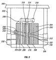
- Figure 2 is an elevation view in cross section of a vibratory source
- Figure 3 is a top view of a ported spacer useful in embodiments of the present disclosure
- Figure 4 is a schematic representation of functional features of a vibratory seismic source such as the source of Figure 1 ;
- Figure 5 is a method flow for generating a seismic source signal.
- FIG. 1 depicts a geophysical survey layout incorporating several aspects of the present disclosure.
- a seismic source 100 is positioned at a predetermined location in an area of exploration and coupled to the earth,
- the seismic source 100 is a truck-carried vibratory seismic source.
- the vibratory seismic source 100 may be a single axis source imparting, for example, only compression P-waves into the earth.
- a multi-axis vibratory source capable of imparting both P and S waves into the earth can be configured according to the present disclosure described in detail herein below without additional illustration or description. Therefore, the present disclosure will focus on a single axis seismic source for brevity and without limiting the scope of the disclosure.
- the seismic source 100 includes a truck 170 having a cab 172 housing a controller 108.
- the seismic source includes a hydraulic subsystem 140 used to move a reaction mass 104.
- the moving reaction mass 104 acts upon a base plate 106 to impart a seismic source signal 102 into with the earth.
- the signal 102 travels through the earth, reflects at discontinuities and formations and travels toward the earth's surface,
- a plurality of sensors 160 are coupled to the earth in an array spaced apart from the seismic source 100.
- the sensors 160 detect the reflected source signal 102, and electrical signals 162, which may be digital and/or analog, are transmitted from the array of sensors 160 to a recording station 164 typically housed in a truck.
- the recording station includes a seismic recorder 168 and may also include a correlation processor, which also receives an electrical signal 180 indicative of the actual source signal 102 imparted into the earth.
- the seismic source 100 comprises several subsystems having system components used in generating the seismic signal 102.
- the system 100 includes a hydraulic pump subsystem 140 having hydraulic lines 142 carrying hydraulic fluid 114 to a servo valve assembly 112.
- a cooler 150 is typically present to cool the hydraulic subsystem.
- Low frequency accumulators 144 mounted on the truck are relatively large, e.g. about ten gallons (37.9 litres) or more, and serve to dampen low frequency noise, e.g. about 25 Hz or less, caused by operation of the hydraulic system.
- FIG 2 is an elevation view in cross section of a vibratory seismic signal source 200 similar to the source 100 described above and shown in Figure 1 .
- the vibratory seismic signal source, or simply source 200 may be carried on a vehicle such as the truck 170 described above and shown in Figure 1 .
- the source 200 includes a lift mechanism assembly 202, a moveable mass 204 and a base plate 206.
- the mass 204 and base plate 206 may each be constructed substantially from a metal such as steel or iron.
- the lift mechanism assembly 202 may be hydraulic, mechanical, electro-mechanical or any mechanism assembly useful for lowering and raising the base plate 206 to engage and disengage the ground.
- a stilt structure 208 extends from the base plate 206 through the mass 204.
- a cross piece 210 which may be constructed from steel or iron I-beam, is coupled to a top section of the stilt structure to provide stability to the stilt structure as the mass 204 vibrates.
- the stilts may be tubular pipes made of steel or iron, although other shapes may be used.
- a piston 212 includes opposing piston rods 214, 216 extending through the mass 204.
- the upper rod 214 being coupled to a hub in the cross piece 210 and the lower rod being coupled to a hub in the base plate 206.
- the piston 212 is slidably received in a cylinder 218 extending vertically through the mass 204.
- Upper and lower annular chambers 220, 222 are located immediately above and below the piston 212 and around the upper and lower piston rods 214, 216. Hydraulic fluid passages 224, 226 lead from respective chambers 220, 222 to a servo-valve assembly 228 mounted on an exterior surface of the mass 204.
- a ported spacer 234 may be mounted between the mass 204 and servo-valve assembly 228.
- Supply and return hydraulic lines ( Figure 1 at 142) couple the servo-valve assembly 228 and one or more small accumulators 230, which are mounted on the mass 204 close to the servo-valve assembly 228, to a hydraulic pump subsystem 140 described above and shown in Figure 1 .
- a pair of high frequency accumulators 230 are mounted as close as practicable to the servo-valve assembly has been found to aid in seismic source signal noise reduction.
- High frequency accumulators 230 relatively small, e.g. about five gallons (18.9 litres) or less, and serve to dampen high frequency noise, e.g.
- Pressure sensors 236 are used to measure supply hydraulic pressure, return hydraulic pressure, and hydraulic pressure to/from hydraulic passageways 224, 226 for use at least in part for control algorithms and methods according to the disclosure.
- Hydraulic fluid 114 pumped to and from the cylinder chambers 220, 222 causes the mass 204 to reciprocally vibrate in a vertical direction.
- the force generated by the vibrating mass is transferred to the base plate 206 via the stilt structure 208 and lower piston rod 216.
- the vibration force is isolated from the vehicle by use of isolators 232 known in the art. The number and position of isolators are determined in part by the shape of the base plate.
- Figure 3 is a top view of a ported spacer 300 useful in embodiments of the present disclosure.
- a servo-valve actuator such as servo valve 228 is mounted to align ports of the servo-valve to corresponding ports on the spacer 300.
- the spacer 3 00 includes a hydraulic fluid supply port 302, a hydraulic fluid system return port 304, and two hydraulic fluid mass control ports 306, 308.
- Passageways 310 provide fluidic coupling for pressure sensors 236, which are not separately shown in this figure.
- the pressure sensors 236 are used to measure supply and control pressures, which measurements are then used at least in part in methods according to the present disclosure.
- the sensors 236 measure pressure high-side supply pressure P H at the supply port 302, supply return pressure P R at the system return port 304, mass control pressure P A to upper chamber 220, and mass control pressure P 8 to lower chamber 222.
- the ported spacer 300 may be made of any material compatible with pressurized hydraulic fluid and with the materials comprising the mass surface and the servo-valve used. Typically a metal such as steel or iron may be used to manufacture the ported spacer by machining or by casting.
- a servo-valve 228 may be manufactured or modified to include passageways 310 and the pressure sensors 236 making the ported spacer an optional feature.
- a ported spacer allows for the use of a commercial off-the-shelf servo-valve without the need for special manufacturing or modification. Both embodiments, i.e. with and/or without a ported spacer, are considered within the scope of the present disclosure.
- Figure 4 schematically illustrates a seismic signal generating system 100 substantially as described above and shown in Figures 1 and 2 , useful for imparting a sinusoidal seismic signal 102 into the earth.
- Reference numerals are aligned with the like components of Figure 1 , but the schematically-illustrated components of Figure 4 are also applicable to similar elements shown on Figure 2 having different reference numerals, which are provided parenthetically below for clarity.
- the base plate 106 (206) is coupled via static weight to the earth.
- the reaction mass 104 (204) is movably coupled to the base plate 106 (206) such that controlled movement of the reaction mass 104 (204) via the hydraulic subsystem 140 vibrates the base plate 106 (206) at a desired amplitude and frequency or sweep to generate the signal 102.
- the controller 108 includes a processor 110 for controlling the system 100.
- the controller is electrically coupled to the servo valve assembly 112 (228).
- the servo valve assembly 112 (228) includes a servo motor 120, a pilot valve 122 and a main stage valve 124.
- the servo valve assembly 112 controls fluid movement in the hydraulic subsystem 140, which provides a force for moving the reaction mass 104 (204).
- An electrical signal 116 having characteristics of the desired sweep signal is transmitted from the controller 108 to the servo motor, which operates the pilot valve 122.
- the pilot valve 122 is coupled to the main stage valve 124 and includes a hydraulic coupling for transferring hydraulic pressure, to operate the main stage valve. When operated, the main stage valve pressurizes and depressurizes hydraulic passages 226, 224 to move the reaction mass 104 (204) according to the controller signal.
- High frequency accumulators 230 reduce or remove servo-valve harmonic distortion of frequencies of about 25 Hz or more, typically 25-30 Hz.
- a problem associated with the typical source generator is distortions of the generated signals, which distortions are caused by characteristics of components comprising the system, e.g., the servo valve assembly 112,
- the servo valve assembly 112 (228) may exhibit characteristics during operation, which generate harmonic distortions in the acoustic signal imparted to the earth. These distortions affect the output of the source and thus all signals received by seismic sensors 160 are degraded.
- the seismic signal 102 is created by regulating the flow of the pressurized hydraulic fluid 114 against the reaction mass 104 , forcing the reaction mass 104 (204) to reciprocate vertically rapidly and repeatedly. Acoustic characteristics of this vibration are controlled by regulating the flow of the hydraulic fluid 114 to adjust the speed and force of the reaction mass 104 .
- Force and phase control may be used to reduce acoustic noise. Force and phase control may be achieved by mounting accelerometers 100 on the reaction mass 104 (204) and the base plate 106 (206) to estimate their respective motions. Once the reaction mass 104 (204) and the base plate 106 (206) are set in motion, the accelerometers 100 transmit motion estimates via signals 138a, 138b to the controller 108 and/or to the correlation processor 166 . When sent to the controller 108 , these motion estimates 138a serve as feedback for a force and phase control algorithm processed by the processor 110 to modify the control signal using a force and phase control signal 136 .
- the control signal 116 modified by the force and phase control signal 136 is then transmitted to the servo-valve assembly 112 (228) for controlling the servo motor 120 to regulate flow of the hydraulic fluid 114 against the reaction mass 104 (204) and, thereby, control the phase and frequency of the seismic signal 102 .
- the control signal 116 provides the principal control input to the servo valve assembly 112, aspects of the disclosure include further control adjustments made using input signals from process sensors 126, 128, 130, 132.
- Several embodiments of the disclosure include one or more sensors measuring hydraulic fluid supply pressure P S , which comprise a high-side pressure sensor P H 126, and a hydraulic fluid discharge or return pressure sensor P R 128. Pressure sensors are collectively numbered 236 in Figure 2 .
- a torque motor current sensor 130, and a main stage valve position indicator 132 may also be used as process sensors.
- the P S sensor 126 estimates the pressure of hydraulic fluid 114 supplied to the servo-valve assembly 112 (228) and the P R sensor 128 estimates hydraulic pressure discharged from the servo valve assembly 112 .
- Electrical signals 134 from any or all of the process sensors 126, 128, 130, 132 is/are transmitted to the controller 108 and processed during operation using the processor 110 .
- a process control signal 139 is then used as a feed-forward signal to the servo valve assembly 112 .
- harmonic distortions generated by the seismic source components e.g. components making up the mechanical, hydraulic and electromechanical components of the servo valve assembly 112 , can be removed partially or completely from the seismic source signal 102 prior to the reaction mass movement generating the signal 102 .
- Figure 5 is a flow diagram of a method according to the disclosure. Aspects of a method 300 according to the disclosure include coupling a seismic source to the earth 302 , initiating seismic source operation 304 , processing a source component initial parameter 306 , controlling the seismic source using the processed initial parameter 308 , and determining one or more operating parameters during operation of the seismic source 310 .
- the operating parameter(s) is/are processed 312 and the seismic source is further controlled using the processed operating parameter(s).
- pressure of the hydraulic subsystem 140 is estimated for P H and P R using the sensors 126 , 128 as source component initial parameters. These initial parameters may alternatively be predetermined initial parameters programmed into the controller 108 prior to initiating operation.
- the initial parameters are transmitted to the processor 110 for processing using a servo-valve control algorithm.
- the processed parameters are used to generate the control signal 139 to adjust operation of the servo motor 124 controlling the pilot valve 122 and main stage valve 124 . These control adjustments remove partially or completely noise created by harmonic distortion from operating the servo-valve assembly.
- the servo-valve control algorithm of Equation 2 is used to further regulate the servo-valve assembly 112 (228) by considering process feedback signals from the torque motor current sensor 134 and the main stage valve position indicator 136 .
- This feed-forward control controls movement of the reaction mass 104 (204) at the beginning of any movement in the system 100 generating harmonic distortion.
- the harmonic distortion is reduced or eliminated within the seismic source system prior to the seismic source signal being imparted into the earth. In this manner, the seismic source signal is much closer to the theoretical control sweep signal 116 and correlation at the recorder is much easier.
Landscapes
- Engineering & Computer Science (AREA)
- Remote Sensing (AREA)
- Physics & Mathematics (AREA)
- Life Sciences & Earth Sciences (AREA)
- Geology (AREA)
- Environmental & Geological Engineering (AREA)
- Acoustics & Sound (AREA)
- General Life Sciences & Earth Sciences (AREA)
- General Physics & Mathematics (AREA)
- Geophysics (AREA)
- Geophysics And Detection Of Objects (AREA)
- Vibration Prevention Devices (AREA)
- Apparatuses For Generation Of Mechanical Vibrations (AREA)
- Supply Devices, Intensifiers, Converters, And Telemotors (AREA)
Abstract
Description
- The present disclosure generally relates to seismic prospecting and in particular to methods and apparatus for generating seismic source signals with reduced signal distortions.
- In the oil and gas exploration industry, geophysical tools and techniques are commonly employed in order to identify a subterranean structure having potential hydrocarbon deposits. Many different techniques are used to generate a seismic signal.
- Seismic vibratory energy sources have been used in the field many years. A seismic vibrator in its simplest form is merely a heavy vehicle that has the ability to shake the ground at a predetermined range of frequencies of about 2 to 100 Hz. The vibrator imparts a signal into the subsurface of the earth over a relatively long period of time, which allows for an energy level less than impulse generators such as dynamite.
- The imparted energy, known as the seismic source signal or "pilot" signal, travels through the subsurface and reflects some of the energy from certain subsurface geological boundaries or layers. The reflected energy is then transmitted back to the earth's surface where it is recorded using an earth motion detector. The recorded data is processed to yield information about a location and physical properties of layers making up the subsurface.
- The seismic vibrator source signal is typically a sweep signal, or simply sweep. Sweeps are sinusoidal vibrations in the 2-100 Hz range described above and having a duration on the order of 2 to 20 seconds depending on the terrain, the subsurface lithology, economic constraints and physical capabilities of the vibrator. The sinusoidal sweep can be increased in frequency overtime, which is called an "upsweep". The upsweep is the signal used typically in modern seismic exploration. Also, the sinusoidal sweep can be decreased in frequency overtime, which is called a "downsweep". The end products of the vibrator sweep are waves that propagate through the earth to return clues about the subsurface.
- A problem with the typical sweep is that the signal imparted into the earth includes distortions caused by harmonic signals generated by one or more of the seismic source components, e.g. the hydraulic, mechanical and electromechanical subsystems making up the source.
WO 98/11357
US-4519053 describes force or pressure feedback controls for seismic vibrators. - The typical method of dealing with such distortions is to measure the signal imparted into the earth using a local sensor such as an accelerometer or geophone located on or close to the base plate coupling the seismic source to the earth. This measured signal is transmitted to a correlation processor, which also receives the signal from geophones or other sensors making up the seismic spread. The correlation processor uses various algorithms to distinguish wave signal data from distortions and other spurious signals. A problem with this method is that the original source signal distortion may vary making correlation difficult. Thus, the cleaner the source signal imparted into the earth the easier the correlation at the recording end of the seismic acquisition process.
- The present disclosure addresses one or more of the above-identified problems found in conventional seismic source generators by providing a seismic source generator generating a seismic source signal having reduced harmonic distortions.
- In one aspect, the present disclosure provides a method for generating a seismic source signal as claimed in claim 1.
- Another aspect of the present disclosure is a seismic source signal apparatus for generating a seismic source signal as claimed in claim 9.
- The feed forward signal may be generated by estimating process parameters such as hydraulic pressure, valve position/displacement and/or electrical current of a control motor. These parameters may then be fed into a controller processor and processed according to one or more algorithms to generate the feed-forward signal. The feed-forward signal adjusts the system ahead of reaction mass movement.
- For detailed understanding of the present disclosure, reference should be made to the following detailed description of the several non-limiting embodiments, taken in conjunction with the accompanying drawings, in which like elements have been given like numerals and wherein:
-
Figure 1 illustrates a typical seismic data acquisition operation utilizing aspects of the present disclosure; -
Figure 2 is an elevation view in cross section of a vibratory source; -
Figure 3 is a top view of a ported spacer useful in embodiments of the present disclosure; -
Figure 4 is a schematic representation of functional features of a vibratory seismic source such as the source ofFigure 1 ; and -
Figure 5 is a method flow for generating a seismic source signal. -
Figure 1 depicts a geophysical survey layout incorporating several aspects of the present disclosure. Aseismic source 100 is positioned at a predetermined location in an area of exploration and coupled to the earth, In the embodiment shown theseismic source 100 is a truck-carried vibratory seismic source. The vibratoryseismic source 100 may be a single axis source imparting, for example, only compression P-waves into the earth. Those skilled in the art would recognize that a multi-axis vibratory source capable of imparting both P and S waves into the earth can be configured according to the present disclosure described in detail herein below without additional illustration or description. Therefore, the present disclosure will focus on a single axis seismic source for brevity and without limiting the scope of the disclosure. - The
seismic source 100 includes atruck 170 having acab 172 housing acontroller 108. The seismic source includes ahydraulic subsystem 140 used to move areaction mass 104. As will be described in more detail in reference toFigure 2 , themoving reaction mass 104 acts upon abase plate 106 to impart aseismic source signal 102 into with the earth. Thesignal 102 travels through the earth, reflects at discontinuities and formations and travels toward the earth's surface, - A plurality of
sensors 160 are coupled to the earth in an array spaced apart from theseismic source 100. Thesensors 160 detect thereflected source signal 102, andelectrical signals 162, which may be digital and/or analog, are transmitted from the array ofsensors 160 to arecording station 164 typically housed in a truck. The recording station includes aseismic recorder 168 and may also include a correlation processor, which also receives anelectrical signal 180 indicative of theactual source signal 102 imparted into the earth. - Still referring to
Figure 1 , theseismic source 100 comprises several subsystems having system components used in generating theseismic signal 102. Thesystem 100 includes ahydraulic pump subsystem 140 having hydraulic lines 142 carryinghydraulic fluid 114 to aservo valve assembly 112. Acooler 150 is typically present to cool the hydraulic subsystem.Low frequency accumulators 144 mounted on the truck are relatively large, e.g. about ten gallons (37.9 litres) or more, and serve to dampen low frequency noise, e.g. about 25 Hz or less, caused by operation of the hydraulic system. -
Figure 2 is an elevation view in cross section of a vibratoryseismic signal source 200 similar to thesource 100 described above and shown inFigure 1 . The vibratory seismic signal source, or simplysource 200, may be carried on a vehicle such as thetruck 170 described above and shown inFigure 1 . Thesource 200 includes alift mechanism assembly 202, amoveable mass 204 and abase plate 206. Themass 204 andbase plate 206 may each be constructed substantially from a metal such as steel or iron. Those skilled in the art are versed in the general materials of construction, so a detailed materials list is not necessary here, Thelift mechanism assembly 202 may be hydraulic, mechanical, electro-mechanical or any mechanism assembly useful for lowering and raising thebase plate 206 to engage and disengage the ground. - A
stilt structure 208 extends from thebase plate 206 through themass 204. Across piece 210, which may be constructed from steel or iron I-beam, is coupled to a top section of the stilt structure to provide stability to the stilt structure as themass 204 vibrates. The stilts may be tubular pipes made of steel or iron, although other shapes may be used. - A
piston 212 includesopposing piston rods mass 204. Theupper rod 214 being coupled to a hub in thecross piece 210 and the lower rod being coupled to a hub in thebase plate 206. Thepiston 212 is slidably received in acylinder 218 extending vertically through themass 204. Upper and lowerannular chambers piston 212 and around the upper andlower piston rods fluid passages respective chambers valve assembly 228 mounted on an exterior surface of themass 204. Alternatively, a ported spacer 234 may be mounted between the mass 204 and servo-valve assembly 228. Supply and return hydraulic lines (Figure 1 at 142) couple the servo-valve assembly 228 and one or moresmall accumulators 230, which are mounted on themass 204 close to the servo-valve assembly 228, to ahydraulic pump subsystem 140 described above and shown inFigure 1 . A pair ofhigh frequency accumulators 230 are mounted as close as practicable to the servo-valve assembly has been found to aid in seismic source signal noise reduction.High frequency accumulators 230 relatively small, e.g. about five gallons (18.9 litres) or less, and serve to dampen high frequency noise, e.g. about 25 Hz or more, caused by operation of the servo-valve assembly 228.Pressure sensors 236 are used to measure supply hydraulic pressure, return hydraulic pressure, and hydraulic pressure to/fromhydraulic passageways -
Hydraulic fluid 114 pumped to and from thecylinder chambers mass 204 to reciprocally vibrate in a vertical direction. The force generated by the vibrating mass is transferred to thebase plate 206 via thestilt structure 208 andlower piston rod 216. The vibration force is isolated from the vehicle by use ofisolators 232 known in the art. The number and position of isolators are determined in part by the shape of the base plate. -
Figure 3 is a top view of a portedspacer 300 useful in embodiments of the present disclosure. A servo-valve actuator such asservo valve 228 is mounted to align ports of the servo-valve to corresponding ports on thespacer 300. The spacer 3 00 includes a hydraulicfluid supply port 302, a hydraulic fluidsystem return port 304, and two hydraulic fluidmass control ports Passageways 310 provide fluidic coupling forpressure sensors 236, which are not separately shown in this figure. Thepressure sensors 236 are used to measure supply and control pressures, which measurements are then used at least in part in methods according to the present disclosure. Thesensors 236 measure pressure high-side supply pressure PH at thesupply port 302, supply return pressure PR at thesystem return port 304, mass control pressure PA toupper chamber 220, and mass control pressure P8 tolower chamber 222. The portedspacer 300 may be made of any material compatible with pressurized hydraulic fluid and with the materials comprising the mass surface and the servo-valve used. Typically a metal such as steel or iron may be used to manufacture the ported spacer by machining or by casting. A servo-valve 228 may be manufactured or modified to includepassageways 310 and thepressure sensors 236 making the ported spacer an optional feature. Using a ported spacer allows for the use of a commercial off-the-shelf servo-valve without the need for special manufacturing or modification.
Both embodiments, i.e. with and/or without a ported spacer, are considered within the scope of the present disclosure. -
Figure 4 schematically illustrates a seismicsignal generating system 100 substantially as described above and shown inFigures 1 and2 , useful for imparting a sinusoidalseismic signal 102 into the earth. Reference numerals are aligned with the like components ofFigure 1 , but the schematically-illustrated components ofFigure 4 are also applicable to similar elements shown onFigure 2 having different reference numerals, which are provided parenthetically below for clarity. The base plate 106 (206) is coupled via static weight to the earth. The reaction mass 104 (204) is movably coupled to the base plate 106 (206) such that controlled movement of the reaction mass 104 (204) via thehydraulic subsystem 140 vibrates the base plate 106 (206) at a desired amplitude and frequency or sweep to generate thesignal 102. Thecontroller 108 includes aprocessor 110 for controlling thesystem 100. The controller is electrically coupled to the servo valve assembly 112 (228). The servo valve assembly 112 (228) includes aservo motor 120, apilot valve 122 and amain stage valve 124. - The servo valve assembly 112 (228) controls fluid movement in the
hydraulic subsystem 140, which provides a force for moving the reaction mass 104 (204). Anelectrical signal 116 having characteristics of the desired sweep signal is transmitted from thecontroller 108 to the servo motor, which operates thepilot valve 122. Thepilot valve 122 is coupled to themain stage valve 124 and includes a hydraulic coupling for transferring hydraulic pressure, to operate the main stage valve. When operated, the main stage valve pressurizes and depressurizeshydraulic passages High frequency accumulators 230 reduce or remove servo-valve harmonic distortion of frequencies of about 25 Hz or more, typically 25-30 Hz. - As noted in the background of the disclosure, a problem associated with the typical source generator is distortions of the generated signals, which distortions are caused by characteristics of components comprising the system, e.g., the
servo valve assembly 112, The servo valve assembly 112 (228) may exhibit characteristics during operation, which generate harmonic distortions in the acoustic signal imparted to the earth. These distortions affect the output of the source and thus all signals received byseismic sensors 160 are degraded. - In aspects of the disclosure the
seismic signal 102 is created by regulating the flow of the pressurizedhydraulic fluid 114 against thereaction mass 104, forcing the reaction mass 104 (204) to reciprocate vertically rapidly and repeatedly. Acoustic characteristics of this vibration are controlled by regulating the flow of thehydraulic fluid 114 to adjust the speed and force of thereaction mass 104. - Force and phase control may be used to reduce acoustic noise. Force and phase control may be achieved by mounting
accelerometers 100 on the reaction mass 104 (204) and the base plate 106 (206) to estimate their respective motions. Once the reaction mass 104 (204) and the base plate 106 (206) are set in motion, theaccelerometers 100 transmit motion estimates viasignals controller 108 and/or to thecorrelation processor 166. When sent to thecontroller 108, thesemotion estimates 138a serve as feedback for a force and phase control algorithm processed by theprocessor 110 to modify the control signal using a force andphase control signal 136. Thecontrol signal 116 modified by the force andphase control signal 136 is then transmitted to the servo-valve assembly 112 (228) for controlling theservo motor 120 to regulate flow of thehydraulic fluid 114 against the reaction mass 104 (204) and, thereby, control the phase and frequency of theseismic signal 102. - The
control signal 116 provides the principal control input to theservo valve assembly 112, aspects of the disclosure include further control adjustments made using input signals fromprocess sensors pressure sensor P H 126, and a hydraulic fluid discharge or returnpressure sensor P R 128. Pressure sensors are collectively numbered 236 inFigure 2 . A torque motorcurrent sensor 130, and a main stagevalve position indicator 132 may also be used as process sensors. The PS sensor 126 estimates the pressure ofhydraulic fluid 114 supplied to the servo-valve assembly 112 (228) and the PR sensor 128 estimates hydraulic pressure discharged from theservo valve assembly 112.Electrical signals 134 from any or all of theprocess sensors controller 108 and processed during operation using theprocessor 110. A process control signal 139 is then used as a feed-forward signal to theservo valve assembly 112. In this manner, harmonic distortions generated by the seismic source components, e.g. components making up the mechanical, hydraulic and electromechanical components of theservo valve assembly 112, can be removed partially or completely from the seismic source signal 102 prior to the reaction mass movement generating thesignal 102. - Having now described the
system 100 and as shown inFigures 1 and2 ,Figure 5 is a flow diagram of a method according to the disclosure. Aspects of amethod 300 according to the disclosure include coupling a seismic source to theearth 302, initiatingseismic source operation 304, processing a source componentinitial parameter 306, controlling the seismic source using the processedinitial parameter 308, and determining one or more operating parameters during operation of theseismic source 310. The operating parameter(s) is/are processed 312 and the seismic source is further controlled using the processed operating parameter(s). - Prior to first generating the
seismic source signal 102, pressure of thehydraulic subsystem 140 is estimated for PH and PR using thesensors controller 108 prior to initiating operation. The initial parameters are transmitted to theprocessor 110 for processing using a servo-valve control algorithm. The processed parameters are used to generate thecontrol signal 139 to adjust operation of theservo motor 124 controlling thepilot valve 122 andmain stage valve 124. These control adjustments remove partially or completely noise created by harmonic distortion from operating the servo-valve assembly. - A primary control algorithm for generating the
primary control signal 116 according to an aspect of the disclosure is:
where: - Q= Hydraulic flow through the servo valve;
- K= Hydraulic flow gain;
- X v = Servo Valve displacement;
- P S = Hydraulic fluid supply pressure, which comprises PH-PR; and
- P L = Hydraulic differential pressure, which comprises control pressures PA-PB.
- The feed-forward control signal 139 may then include the reciprocal of the radical of equation 1 or:

where: - C is the control gain;
- K2 is the square root of the difference between supply pressure PH and Return Pressure PR, i.e.

- ε is a small positive number that effectively limits the maximum gain; and
- PS > |PL|.
- The servo-valve control algorithm of Equation 2 is used to further regulate the servo-valve assembly 112 (228) by considering process feedback signals from the torque motor
current sensor 134 and the main stagevalve position indicator 136. This feed-forward control controls movement of the reaction mass 104 (204) at the beginning of any movement in thesystem 100 generating harmonic distortion. Thus, the harmonic distortion is reduced or eliminated within the seismic source system prior to the seismic source signal being imparted into the earth. In this manner, the seismic source signal is much closer to the theoreticalcontrol sweep signal 116 and correlation at the recorder is much easier. - The present disclosure is to be taken as illustrative rather than as limiting the scope or nature of the claims below. Numerous modifications and variations will become apparent to those skilled in the art after studying the disclosure, including use of equivalent functional and/or structural substitutes for elements described herein, use of equivalent functional couplings for couplings described herein, and/or use of equivalent functional actions for actions described herein. Such Insubstantial variations are to be considered within the scope of the claims below.
- Given the above disclosure of general concepts and specific embodiments, the scope of protection is defined by the claims appended hereto.
Claims (15)
- A method for generating a seismic source signal comprising:a) coupling a seismic source (100) to the earth using a base plate (106;206);b) initiating operation of the seismic source (100);c) processing an initial parameter of a source component using a processor (110), the initial parameter comprising a hydraulic supply pressure and a hydraulic differential pressure;d) controlling the seismic source (100) using a feed-forward signal comprising the processed initial parameter;e) determining an operating parameter during operation of the seismic source (100), the operating parameter comprising a hydraulic supply pressure and a hydraulic differential pressure;f) processing the operating parameter using the processor (110) to adjust the feed-forward signal; andg) controlling the seismic source (100) using the adjusted feed-forward signal,wherein an output of the seismic source includes the seismic source signal imparted into the earth with harmonic distortions generated by the source component at least partially removed from the seismic source signal.
- A method according to claim 1, wherein the seismic source (100) comprises a vibratory seismic source and initiating operation includes generating an electrical control signal to a servo valve assembly (112).
- A method according to claim 2, wherein the electrical control signal comprises a sinusoid signal.
- A method according to claim 3, wherein the sinusoid signal comprises a variable frequency signal.
- A method according to claim 1, wherein the initial parameter includes a hydraulic supply pressure and hydraulic supply return pressure.
- A method according to claim 1, wherein the seismic source (100) comprises a hydraulic subsystem (140) and the operating parameter comprises a hydraulic subsystem pressure.
- A method according to claim 1, wherein the seismic source comprises servo valve assembly (112) and determining the operating parameter includes determining a parameter of the servo valve assembly (112).
- A method according to claim 1, wherein the seismic source (100) comprises servo valve assembly and a servo motor operating the servo valve assembly (112), and determining the operating parameter includes determining an electrical current used to operate the servo motor.
- A seismic source signal apparatus for generating a seismic source signal, the apparatus comprising:a) a base plate (106;206) for coupling the seismic source (100) to the earth;b) a seismic source component;c) a sensor sensing an operating parameter of the seismic source component;d) a processor (110) processing an initial parameter and processing the operating parameter during operation of the seismic source (100) to generate a feed-forward signal, the initial parameter and operating parameter each comprising a hydraulic supply pressure and a hydraulic differential pressure; ande) one or more controllers (108) controlling the seismic source (100) using the feed-forward signal;wherein an output of the seismic source (100) includes the seismic source signal imparted into the earth with harmonic distortions generated by the source component at least partially removed from the seismic source signal.
- An apparatus according to claim 9, wherein the seismic source (100) comprises a vibratory seismic source and a servo valve assembly (112), and wherein the one or more controllers (108) initiate operation of the apparatus by generating an electrical control signal to the servo valve assembly (112).
- An apparatus according to claim 10, wherein the electrical control signal comprises a sinusoid signal.
- An apparatus according to claim 11, wherein the sinusoid signal comprises a variable frequency signal.
- An apparatus according to claim 9, wherein the seismic source (100) comprises servo valve assembly (112) and the operating parameter includes a parameter of the servo valve assembly (112).
- An apparatus according to claim 9, wherein the seismic source (100) comprises servo valve assembly (112) and the initial parameter includes a parameter of the servo valve assembly (112).
- An apparatus according to claim 9, wherein the seismic source comprises servo valve assembly (112) and a servo motor operating the servo valve assembly (112) the operating parameter including an electrical current used to operate the servo motor.
Applications Claiming Priority (3)
| Application Number | Priority Date | Filing Date | Title |
|---|---|---|---|
| US78622406P | 2006-03-27 | 2006-03-27 | |
| US82528506P | 2006-09-12 | 2006-09-12 | |
| PCT/US2007/007525 WO2007126786A2 (en) | 2006-03-27 | 2007-03-27 | Apparatus and method for generating a seismic source signal |
Publications (3)
| Publication Number | Publication Date |
|---|---|
| EP1999489A2 EP1999489A2 (en) | 2008-12-10 |
| EP1999489A4 EP1999489A4 (en) | 2011-12-28 |
| EP1999489B1 true EP1999489B1 (en) | 2013-12-25 |
Family
ID=38656011
Family Applications (2)
| Application Number | Title | Priority Date | Filing Date |
|---|---|---|---|
| EP07754096.1A Not-in-force EP1999489B1 (en) | 2006-03-27 | 2007-03-27 | Apparatus and method for generating a seismic source signal |
| EP07754094.6A Not-in-force EP1999490B1 (en) | 2006-03-27 | 2007-03-27 | Apparatus and method for generating a seismic source signal |
Family Applications After (1)
| Application Number | Title | Priority Date | Filing Date |
|---|---|---|---|
| EP07754094.6A Not-in-force EP1999490B1 (en) | 2006-03-27 | 2007-03-27 | Apparatus and method for generating a seismic source signal |
Country Status (4)
| Country | Link |
|---|---|
| US (4) | US7929380B2 (en) |
| EP (2) | EP1999489B1 (en) |
| CA (2) | CA2646558C (en) |
| WO (2) | WO2007126785A2 (en) |
Families Citing this family (41)
| Publication number | Priority date | Publication date | Assignee | Title |
|---|---|---|---|---|
| US7929380B2 (en) * | 2006-03-27 | 2011-04-19 | Inova Ltd. | Apparatus and method for generating a seismic source signal |
| US7843768B2 (en) * | 2008-04-11 | 2010-11-30 | Squire James C | System for communicating location of survivors in mine emergencies |
| RU2503976C2 (en) * | 2009-05-01 | 2014-01-10 | Айнова Лтд. | Seismic vibrator controlled by directly detecting base plate motion |
| US8335127B2 (en) * | 2009-08-12 | 2012-12-18 | Pgs Geophysical As | Method for generating spread spectrum driver signals for a seismic vibrator array using multiple biphase modulation operations in each driver signal chip |
| US8274862B2 (en) * | 2009-10-09 | 2012-09-25 | CGG Veritas | System and method for determining a frequency sweep for seismic analysis |
| US20110272206A1 (en) * | 2010-05-05 | 2011-11-10 | Conocophillips Company | Matrix ground force measurement of seismic transducers and methods of use |
| US8446798B2 (en) | 2010-06-29 | 2013-05-21 | Pgs Geophysical As | Marine acoustic vibrator having enhanced low-frequency amplitude |
| US8325559B2 (en) | 2010-08-27 | 2012-12-04 | Board Of Regents Of The University Of Texas System | Extracting SV shear data from P-wave marine data |
| US8040754B1 (en) | 2010-08-27 | 2011-10-18 | Board Of Regents Of The University Of Texas System | System and method for acquisition and processing of elastic wavefield seismic data |
| US8243548B2 (en) | 2010-08-27 | 2012-08-14 | Board Of Regents Of The University Of Texas System | Extracting SV shear data from P-wave seismic data |
| CA2813298A1 (en) | 2010-08-30 | 2012-03-08 | Conocophilips Company | Baseplate dampening pad |
| US20120075955A1 (en) * | 2010-09-28 | 2012-03-29 | Timothy Dean | Efficient seismic source operation in connection with a seismic survey |
| CA2814216A1 (en) | 2010-10-14 | 2012-04-19 | Inova Ltd. | Seismic vibrator having composite baseplate |
| CN103238087B (en) | 2010-10-14 | 2016-05-04 | 英洛瓦有限公司 | The seismic data filtering of the Earth model based on coupled vibrations device |
| CN102146684B (en) * | 2011-03-07 | 2012-12-26 | 北京工业大学 | Device used for simulating foundation radiation damping effect in vibration table test |
| US10020895B2 (en) | 2011-06-22 | 2018-07-10 | David H. Parker | Methods and apparatus for emergency mine communications using acoustic waves, time synchronization, and digital signal processing |
| US8670292B2 (en) | 2011-08-12 | 2014-03-11 | Pgs Geophysical As | Electromagnetic linear actuators for marine acoustic vibratory sources |
| CA2863705A1 (en) * | 2012-02-08 | 2013-08-15 | Inova Ltd. | Method of seismic vibratory limits control at low frequencies |
| US8797036B2 (en) * | 2012-02-29 | 2014-08-05 | Pgs Geophysical | Methods and apparatus for adaptive source electromagnetic surveying |
| CA2869424A1 (en) * | 2012-04-04 | 2013-10-10 | Inova Ltd. | Devices and systems for controlling harmonic distortion in seismic sources |
| US10473803B2 (en) | 2013-02-08 | 2019-11-12 | Pgs Geophysical As | Marine seismic vibrators and methods of use |
| US20140238771A1 (en) * | 2013-02-22 | 2014-08-28 | Cgg Services Sa | Marine acoustic projector piston for vibrator source element and method |
| US20140247697A1 (en) * | 2013-03-01 | 2014-09-04 | Westerngeco L.L.C. | Seismic source calibration technique and system |
| US9322945B2 (en) | 2013-03-06 | 2016-04-26 | Pgs Geophysical As | System and method for seismic surveying using distributed sources |
| US9217797B2 (en) | 2013-04-11 | 2015-12-22 | Schlumberger Technology Corporation | High-speed image monitoring of baseplate movement in a vibrator |
| US9645264B2 (en) | 2013-05-07 | 2017-05-09 | Pgs Geophysical As | Pressure-compensated sources |
| US9995834B2 (en) | 2013-05-07 | 2018-06-12 | Pgs Geophysical As | Variable mass load marine vibrator |
| US9864080B2 (en) | 2013-05-15 | 2018-01-09 | Pgs Geophysical As | Gas spring compensation marine acoustic vibrator |
| US10222495B2 (en) * | 2013-06-04 | 2019-03-05 | Mi-Holding Bv | Seismic shaker |
| US9360574B2 (en) | 2013-09-20 | 2016-06-07 | Pgs Geophysical As | Piston-type marine vibrators comprising a compliance chamber |
| US9341725B2 (en) | 2013-09-20 | 2016-05-17 | Pgs Geophysical As | Piston integrated variable mass load |
| US9507037B2 (en) | 2013-09-20 | 2016-11-29 | Pgs Geophysical As | Air-spring compensation in a piston-type marine vibrator |
| US9618637B2 (en) | 2013-09-20 | 2017-04-11 | Pgs Geophysical As | Low frequency marine acoustic vibrator |
| US9612347B2 (en) | 2014-08-14 | 2017-04-04 | Pgs Geophysical As | Compliance chambers for marine vibrators |
| CN104155684B (en) * | 2014-08-25 | 2016-11-16 | 中国矿业大学 | Self-compensating vibroseis and source generation method for shock wave CT detection of shock wave CT detection in underground coal seam working face |
| US9766361B2 (en) | 2014-10-10 | 2017-09-19 | Pgs Geophysical As | Methods and apparatus for electromagnetic surveying using dynamically-selected source waveforms |
| US9389327B2 (en) | 2014-10-15 | 2016-07-12 | Pgs Geophysical As | Compliance chambers for marine vibrators |
| US10488542B2 (en) | 2014-12-02 | 2019-11-26 | Pgs Geophysical As | Use of external driver to energize a seismic source |
| CA2984784C (en) * | 2015-04-29 | 2023-08-29 | Conocophillips Company | Downhole inertial mass system |
| US9726770B2 (en) | 2015-05-14 | 2017-08-08 | Conocophillips Company | Multiple actuator vibrator |
| US11693136B2 (en) * | 2019-10-31 | 2023-07-04 | Sercel | Seismic vibrator with adjustable resonance frequency |
Family Cites Families (37)
| Publication number | Priority date | Publication date | Assignee | Title |
|---|---|---|---|---|
| ES280515A1 (en) * | 1961-09-04 | 1963-05-01 | Inst Francais Du Petrole Des Carburants Et Lubrificants | Vibrator a hydraulic cat with servomechanism (Machine-translation by Google Translate, not legally binding) |
| US3439773A (en) * | 1967-05-05 | 1969-04-22 | Sinclair Research Inc | Method of and apparatus for imparting a seismic pulse to the earth |
| US3860087A (en) * | 1972-02-07 | 1975-01-14 | Daniel Silverman | Vibrator systems for generating elastic waves in the earth |
| US3934673A (en) * | 1972-02-07 | 1976-01-27 | Daniel Silverman | Vibrator systems for generating elastic waves in the earth |
| US3795286A (en) * | 1972-02-23 | 1974-03-05 | Texaco Inc | Apparatus and means for inducing vibrations in an earth formation |
| US3929206A (en) | 1973-04-30 | 1975-12-30 | Texas Instruments Corp | Servo hydraulic transducer and method of operation |
| US4049077A (en) * | 1974-10-21 | 1977-09-20 | Exxon Production Research Company | Seismic vibrator control system |
| US4147228A (en) * | 1976-10-07 | 1979-04-03 | Hydroacoustics Inc. | Methods and apparatus for the generation and transmission of seismic signals |
| US4103756A (en) * | 1976-12-21 | 1978-08-01 | Applied Theory, Inc. | Stress wave generator |
| US4143736A (en) * | 1977-11-03 | 1979-03-13 | Continental Oil Company | Seismic transducer construction |
| US4336745A (en) | 1978-07-31 | 1982-06-29 | Mts Systems Corporation | Servovalve flow linearization circuit |
| WO1981000459A1 (en) * | 1979-08-13 | 1981-02-19 | Conoco Inc | Mobile high frequency vibrator system |
| US4519053A (en) * | 1981-11-27 | 1985-05-21 | Texas Instruments Incorporated | Force or pressure feedback control for seismic vibrators |
| US4442755A (en) * | 1982-01-25 | 1984-04-17 | Litton Resources Systems, Inc. | Power stage servo valve for a seismic vibrator |
| US4658930A (en) * | 1982-09-28 | 1987-04-21 | Industrial Vehicles International, Inc. | Vibrator for seismic geophysical prospecting |
| US4637002A (en) * | 1984-03-05 | 1987-01-13 | Texas Instruments Incorporated | Seismic source vibrator having self tuning controller |
| FR2563919B1 (en) * | 1984-05-02 | 1987-03-20 | Inst Francais Du Petrole | DEVICE FOR APPLYING IMPULSE RADIAL CONSTRAINTS TO THE WALL OF A WELL |
| US4718049A (en) * | 1986-01-23 | 1988-01-05 | Western Atlas International, Inc. | Pre-loaded vibrator assembly with mechanical lock |
| US5005665A (en) * | 1986-06-16 | 1991-04-09 | The Standard Oil Company | Piezoelectric seismic vibration device and method |
| FR2658304B1 (en) * | 1990-02-14 | 1992-08-28 | Schlumberger Prospection | BOTTOM SEISMIC SOURCE AND METHOD FOR CREATING ACOUSTIC WAVES IN A WELLBORE. |
| US5128908A (en) * | 1990-04-09 | 1992-07-07 | Reust Dennis K | Pressure feedback servovalve for a seismic vibrator |
| US5113966A (en) * | 1990-04-19 | 1992-05-19 | The United States Of America As Represented By The United States Department Of Energy | Downhole hydraulic seismic generator |
| US5018598A (en) * | 1990-06-18 | 1991-05-28 | Emil A. Nakfoor | Apparatus for generating seismic waves |
| AU5951894A (en) | 1992-12-14 | 1994-07-04 | Western Atlas International, Inc. | Removable piston bore liner for hydraulically actuated seismic vibrator |
| US5491306A (en) * | 1994-03-25 | 1996-02-13 | Mts Systems Corporation | Mass oscillator having an adjustable gas spring |
| AU4251797A (en) * | 1996-09-12 | 1998-04-02 | Etrema Products, Inc. | Compact actuator and controller and pumping apparatus for same |
| US5666328A (en) | 1996-10-18 | 1997-09-09 | I/O Exploration Products (U.S.A.), Inc. | Three axis seismic vibrator |
| US6065562A (en) * | 1998-07-27 | 2000-05-23 | Industrial Vehicles International, Inc. | System for imparting compressional and shear waves into the earth |
| US6152256A (en) * | 1998-10-29 | 2000-11-28 | Aspect Resources Llc | Method for controlling seismic vibrator ground forces |
| FR2791780B1 (en) | 1999-03-30 | 2001-05-04 | Inst Francais Du Petrole | COMPACT VIBRATOR AND METHOD OF MONITORING OR SEISMIC PROSPECTION USING SUCH A VIBRATOR |
| US6253549B1 (en) * | 1999-04-26 | 2001-07-03 | Loran D. Ambs | Toroidal hydraulic actuator |
| US6552961B1 (en) * | 2000-08-22 | 2003-04-22 | Westerngeco, L.L.C. | Seismic source sensor |
| US6561310B2 (en) * | 2001-03-07 | 2003-05-13 | Conocophillips Company | Method and apparatus for measuring seismic energy imparted to the earth |
| US6671224B1 (en) * | 2002-08-26 | 2003-12-30 | Schlumberger Technology Corporation | Active reduction of tool borne noise in a sonic logging tool |
| US7364008B2 (en) * | 2004-05-14 | 2008-04-29 | 969912 Alberta Ltd. | System for imparting mechanical impulse energy to the ground |
| US7411863B2 (en) * | 2006-03-10 | 2008-08-12 | Westerngeco L.L.C. | Marine seismic data acquisition systems and methods |
| US7929380B2 (en) * | 2006-03-27 | 2011-04-19 | Inova Ltd. | Apparatus and method for generating a seismic source signal |
-
2007
- 2007-03-27 US US11/691,925 patent/US7929380B2/en active Active
- 2007-03-27 EP EP07754096.1A patent/EP1999489B1/en not_active Not-in-force
- 2007-03-27 WO PCT/US2007/007523 patent/WO2007126785A2/en not_active Ceased
- 2007-03-27 WO PCT/US2007/007525 patent/WO2007126786A2/en not_active Ceased
- 2007-03-27 US US11/691,941 patent/US7628248B2/en active Active
- 2007-03-27 CA CA2646558A patent/CA2646558C/en active Active
- 2007-03-27 EP EP07754094.6A patent/EP1999490B1/en not_active Not-in-force
- 2007-03-27 CA CA2646564A patent/CA2646564C/en not_active Expired - Fee Related
-
2009
- 2009-11-23 US US12/623,752 patent/US7987943B2/en active Active
-
2011
- 2011-03-16 US US13/049,713 patent/US8134891B2/en active Active
Also Published As
| Publication number | Publication date |
|---|---|
| EP1999489A2 (en) | 2008-12-10 |
| WO2007126786A2 (en) | 2007-11-08 |
| WO2007126785A2 (en) | 2007-11-08 |
| US8134891B2 (en) | 2012-03-13 |
| US7987943B2 (en) | 2011-08-02 |
| EP1999490A2 (en) | 2008-12-10 |
| US7628248B2 (en) | 2009-12-08 |
| US20070240930A1 (en) | 2007-10-18 |
| WO2007126786A3 (en) | 2008-02-21 |
| US20100071989A1 (en) | 2010-03-25 |
| CA2646564A1 (en) | 2007-11-08 |
| EP1999490B1 (en) | 2013-08-07 |
| CA2646558C (en) | 2017-10-24 |
| WO2007126785A3 (en) | 2008-10-30 |
| CA2646564C (en) | 2015-02-17 |
| EP1999490A4 (en) | 2011-10-26 |
| CA2646558A1 (en) | 2007-11-08 |
| US20110164470A1 (en) | 2011-07-07 |
| US20070250269A1 (en) | 2007-10-25 |
| EP1999489A4 (en) | 2011-12-28 |
| US7929380B2 (en) | 2011-04-19 |
Similar Documents
| Publication | Publication Date | Title |
|---|---|---|
| CA2646564C (en) | Apparatus and method for generating a seismic source signal | |
| EP2834671B1 (en) | Devices and systems for controlling harmonic distortion in seismic sources | |
| EP2425277B1 (en) | Seismic vibrator controlled by directly detecting base plate motion | |
| EP3090286B1 (en) | Control system for marine vibrators operating near impulsive seismic signal sources | |
| Wei et al. | Fundamental discussions on seismic vibrators | |
| US10302783B2 (en) | Compliance chambers for marine vibrators | |
| AU2013216795B2 (en) | Method of seismic vibratory limits control at low frequencies | |
| Wei et al. | Geophysical benefits from an improved seismic vibrator | |
| Wei et al. | A new generation low-frequency seismic vibrator | |
| EP3127257B1 (en) | Method for separating seismic source data |
Legal Events
| Date | Code | Title | Description |
|---|---|---|---|
| PUAI | Public reference made under article 153(3) epc to a published international application that has entered the european phase |
Free format text: ORIGINAL CODE: 0009012 |
|
| 17P | Request for examination filed |
Effective date: 20080922 |
|
| AK | Designated contracting states |
Kind code of ref document: A2 Designated state(s): AT BE BG CH CY CZ DE DK EE ES FI FR GB GR HU IE IS IT LI LT LU LV MC MT NL PL PT RO SE SI SK TR |
|
| RAP1 | Party data changed (applicant data changed or rights of an application transferred) |
Owner name: INOVA LTD. |
|
| A4 | Supplementary search report drawn up and despatched |
Effective date: 20111129 |
|
| RIC1 | Information provided on ipc code assigned before grant |
Ipc: G01V 1/04 20060101AFI20111123BHEP Ipc: G01V 1/40 20060101ALI20111123BHEP |
|
| DAX | Request for extension of the european patent (deleted) | ||
| 17Q | First examination report despatched |
Effective date: 20130117 |
|
| GRAP | Despatch of communication of intention to grant a patent |
Free format text: ORIGINAL CODE: EPIDOSNIGR1 |
|
| INTG | Intention to grant announced |
Effective date: 20130710 |
|
| GRAS | Grant fee paid |
Free format text: ORIGINAL CODE: EPIDOSNIGR3 |
|
| GRAA | (expected) grant |
Free format text: ORIGINAL CODE: 0009210 |
|
| AK | Designated contracting states |
Kind code of ref document: B1 Designated state(s): AT BE BG CH CY CZ DE DK EE ES FI FR GB GR HU IE IS IT LI LT LU LV MC MT NL PL PT RO SE SI SK TR |
|
| REG | Reference to a national code |
Ref country code: GB Ref legal event code: FG4D |
|
| REG | Reference to a national code |
Ref country code: CH Ref legal event code: EP |
|
| REG | Reference to a national code |
Ref country code: AT Ref legal event code: REF Ref document number: 646889 Country of ref document: AT Kind code of ref document: T Effective date: 20140115 |
|
| REG | Reference to a national code |
Ref country code: IE Ref legal event code: FG4D |
|
| REG | Reference to a national code |
Ref country code: NL Ref legal event code: T3 |
|
| REG | Reference to a national code |
Ref country code: DE Ref legal event code: R096 Ref document number: 602007034454 Country of ref document: DE Effective date: 20140213 |
|
| PG25 | Lapsed in a contracting state [announced via postgrant information from national office to epo] |
Ref country code: LT Free format text: LAPSE BECAUSE OF FAILURE TO SUBMIT A TRANSLATION OF THE DESCRIPTION OR TO PAY THE FEE WITHIN THE PRESCRIBED TIME-LIMIT Effective date: 20131225 Ref country code: FI Free format text: LAPSE BECAUSE OF FAILURE TO SUBMIT A TRANSLATION OF THE DESCRIPTION OR TO PAY THE FEE WITHIN THE PRESCRIBED TIME-LIMIT Effective date: 20131225 Ref country code: SE Free format text: LAPSE BECAUSE OF FAILURE TO SUBMIT A TRANSLATION OF THE DESCRIPTION OR TO PAY THE FEE WITHIN THE PRESCRIBED TIME-LIMIT Effective date: 20131225 |
|
| PGFP | Annual fee paid to national office [announced via postgrant information from national office to epo] |
Ref country code: NL Payment date: 20140308 Year of fee payment: 8 |
|
| REG | Reference to a national code |
Ref country code: AT Ref legal event code: MK05 Ref document number: 646889 Country of ref document: AT Kind code of ref document: T Effective date: 20131225 |
|
| REG | Reference to a national code |
Ref country code: LT Ref legal event code: MG4D |
|
| PG25 | Lapsed in a contracting state [announced via postgrant information from national office to epo] |
Ref country code: LV Free format text: LAPSE BECAUSE OF FAILURE TO SUBMIT A TRANSLATION OF THE DESCRIPTION OR TO PAY THE FEE WITHIN THE PRESCRIBED TIME-LIMIT Effective date: 20131225 |
|
| PG25 | Lapsed in a contracting state [announced via postgrant information from national office to epo] |
Ref country code: BE Free format text: LAPSE BECAUSE OF FAILURE TO SUBMIT A TRANSLATION OF THE DESCRIPTION OR TO PAY THE FEE WITHIN THE PRESCRIBED TIME-LIMIT Effective date: 20131225 Ref country code: IS Free format text: LAPSE BECAUSE OF FAILURE TO SUBMIT A TRANSLATION OF THE DESCRIPTION OR TO PAY THE FEE WITHIN THE PRESCRIBED TIME-LIMIT Effective date: 20140425 Ref country code: EE Free format text: LAPSE BECAUSE OF FAILURE TO SUBMIT A TRANSLATION OF THE DESCRIPTION OR TO PAY THE FEE WITHIN THE PRESCRIBED TIME-LIMIT Effective date: 20131225 |
|
| PG25 | Lapsed in a contracting state [announced via postgrant information from national office to epo] |
Ref country code: CY Free format text: LAPSE BECAUSE OF FAILURE TO SUBMIT A TRANSLATION OF THE DESCRIPTION OR TO PAY THE FEE WITHIN THE PRESCRIBED TIME-LIMIT Effective date: 20131225 Ref country code: ES Free format text: LAPSE BECAUSE OF FAILURE TO SUBMIT A TRANSLATION OF THE DESCRIPTION OR TO PAY THE FEE WITHIN THE PRESCRIBED TIME-LIMIT Effective date: 20131225 Ref country code: AT Free format text: LAPSE BECAUSE OF FAILURE TO SUBMIT A TRANSLATION OF THE DESCRIPTION OR TO PAY THE FEE WITHIN THE PRESCRIBED TIME-LIMIT Effective date: 20131225 Ref country code: CZ Free format text: LAPSE BECAUSE OF FAILURE TO SUBMIT A TRANSLATION OF THE DESCRIPTION OR TO PAY THE FEE WITHIN THE PRESCRIBED TIME-LIMIT Effective date: 20131225 Ref country code: PL Free format text: LAPSE BECAUSE OF FAILURE TO SUBMIT A TRANSLATION OF THE DESCRIPTION OR TO PAY THE FEE WITHIN THE PRESCRIBED TIME-LIMIT Effective date: 20131225 Ref country code: SK Free format text: LAPSE BECAUSE OF FAILURE TO SUBMIT A TRANSLATION OF THE DESCRIPTION OR TO PAY THE FEE WITHIN THE PRESCRIBED TIME-LIMIT Effective date: 20131225 Ref country code: PT Free format text: LAPSE BECAUSE OF FAILURE TO SUBMIT A TRANSLATION OF THE DESCRIPTION OR TO PAY THE FEE WITHIN THE PRESCRIBED TIME-LIMIT Effective date: 20140428 Ref country code: RO Free format text: LAPSE BECAUSE OF FAILURE TO SUBMIT A TRANSLATION OF THE DESCRIPTION OR TO PAY THE FEE WITHIN THE PRESCRIBED TIME-LIMIT Effective date: 20131225 |
|
| PGFP | Annual fee paid to national office [announced via postgrant information from national office to epo] |
Ref country code: DE Payment date: 20140417 Year of fee payment: 8 |
|
| REG | Reference to a national code |
Ref country code: DE Ref legal event code: R097 Ref document number: 602007034454 Country of ref document: DE |
|
| PG25 | Lapsed in a contracting state [announced via postgrant information from national office to epo] |
Ref country code: DK Free format text: LAPSE BECAUSE OF FAILURE TO SUBMIT A TRANSLATION OF THE DESCRIPTION OR TO PAY THE FEE WITHIN THE PRESCRIBED TIME-LIMIT Effective date: 20131225 Ref country code: LU Free format text: LAPSE BECAUSE OF FAILURE TO SUBMIT A TRANSLATION OF THE DESCRIPTION OR TO PAY THE FEE WITHIN THE PRESCRIBED TIME-LIMIT Effective date: 20140327 |
|
| PLBE | No opposition filed within time limit |
Free format text: ORIGINAL CODE: 0009261 |
|
| REG | Reference to a national code |
Ref country code: CH Ref legal event code: PL |
|
| STAA | Information on the status of an ep patent application or granted ep patent |
Free format text: STATUS: NO OPPOSITION FILED WITHIN TIME LIMIT |
|
| 26N | No opposition filed |
Effective date: 20140926 |
|
| REG | Reference to a national code |
Ref country code: IE Ref legal event code: MM4A |
|
| REG | Reference to a national code |
Ref country code: DE Ref legal event code: R097 Ref document number: 602007034454 Country of ref document: DE Effective date: 20140926 |
|
| PG25 | Lapsed in a contracting state [announced via postgrant information from national office to epo] |
Ref country code: CH Free format text: LAPSE BECAUSE OF NON-PAYMENT OF DUE FEES Effective date: 20140331 Ref country code: LI Free format text: LAPSE BECAUSE OF NON-PAYMENT OF DUE FEES Effective date: 20140331 Ref country code: IE Free format text: LAPSE BECAUSE OF NON-PAYMENT OF DUE FEES Effective date: 20140327 |
|
| PG25 | Lapsed in a contracting state [announced via postgrant information from national office to epo] |
Ref country code: SI Free format text: LAPSE BECAUSE OF FAILURE TO SUBMIT A TRANSLATION OF THE DESCRIPTION OR TO PAY THE FEE WITHIN THE PRESCRIBED TIME-LIMIT Effective date: 20131225 |
|
| REG | Reference to a national code |
Ref country code: DE Ref legal event code: R119 Ref document number: 602007034454 Country of ref document: DE |
|
| REG | Reference to a national code |
Ref country code: NL Ref legal event code: MM Effective date: 20150401 |
|
| PG25 | Lapsed in a contracting state [announced via postgrant information from national office to epo] |
Ref country code: DE Free format text: LAPSE BECAUSE OF NON-PAYMENT OF DUE FEES Effective date: 20151001 |
|
| REG | Reference to a national code |
Ref country code: FR Ref legal event code: PLFP Year of fee payment: 10 |
|
| PG25 | Lapsed in a contracting state [announced via postgrant information from national office to epo] |
Ref country code: MT Free format text: LAPSE BECAUSE OF FAILURE TO SUBMIT A TRANSLATION OF THE DESCRIPTION OR TO PAY THE FEE WITHIN THE PRESCRIBED TIME-LIMIT Effective date: 20131225 |
|
| PG25 | Lapsed in a contracting state [announced via postgrant information from national office to epo] |
Ref country code: MC Free format text: LAPSE BECAUSE OF FAILURE TO SUBMIT A TRANSLATION OF THE DESCRIPTION OR TO PAY THE FEE WITHIN THE PRESCRIBED TIME-LIMIT Effective date: 20131225 Ref country code: BG Free format text: LAPSE BECAUSE OF FAILURE TO SUBMIT A TRANSLATION OF THE DESCRIPTION OR TO PAY THE FEE WITHIN THE PRESCRIBED TIME-LIMIT Effective date: 20131225 |
|
| PGFP | Annual fee paid to national office [announced via postgrant information from national office to epo] |
Ref country code: GB Payment date: 20160323 Year of fee payment: 10 Ref country code: FR Payment date: 20160208 Year of fee payment: 10 |
|
| PG25 | Lapsed in a contracting state [announced via postgrant information from national office to epo] |
Ref country code: IT Free format text: LAPSE BECAUSE OF FAILURE TO SUBMIT A TRANSLATION OF THE DESCRIPTION OR TO PAY THE FEE WITHIN THE PRESCRIBED TIME-LIMIT Effective date: 20131225 Ref country code: GR Free format text: LAPSE BECAUSE OF FAILURE TO SUBMIT A TRANSLATION OF THE DESCRIPTION OR TO PAY THE FEE WITHIN THE PRESCRIBED TIME-LIMIT Effective date: 20140326 |
|
| PG25 | Lapsed in a contracting state [announced via postgrant information from national office to epo] |
Ref country code: HU Free format text: LAPSE BECAUSE OF FAILURE TO SUBMIT A TRANSLATION OF THE DESCRIPTION OR TO PAY THE FEE WITHIN THE PRESCRIBED TIME-LIMIT; INVALID AB INITIO Effective date: 20070327 Ref country code: TR Free format text: LAPSE BECAUSE OF FAILURE TO SUBMIT A TRANSLATION OF THE DESCRIPTION OR TO PAY THE FEE WITHIN THE PRESCRIBED TIME-LIMIT Effective date: 20131225 |
|
| PG25 | Lapsed in a contracting state [announced via postgrant information from national office to epo] |
Ref country code: NL Free format text: LAPSE BECAUSE OF NON-PAYMENT OF DUE FEES Effective date: 20150401 |
|
| GBPC | Gb: european patent ceased through non-payment of renewal fee |
Effective date: 20170327 |
|
| REG | Reference to a national code |
Ref country code: FR Ref legal event code: ST Effective date: 20171130 |
|
| PG25 | Lapsed in a contracting state [announced via postgrant information from national office to epo] |
Ref country code: FR Free format text: LAPSE BECAUSE OF NON-PAYMENT OF DUE FEES Effective date: 20170331 |
|
| PG25 | Lapsed in a contracting state [announced via postgrant information from national office to epo] |
Ref country code: GB Free format text: LAPSE BECAUSE OF NON-PAYMENT OF DUE FEES Effective date: 20170327 |