EP1999004B1 - Gear drive system and method - Google Patents
Gear drive system and method Download PDFInfo
- Publication number
- EP1999004B1 EP1999004B1 EP07759345A EP07759345A EP1999004B1 EP 1999004 B1 EP1999004 B1 EP 1999004B1 EP 07759345 A EP07759345 A EP 07759345A EP 07759345 A EP07759345 A EP 07759345A EP 1999004 B1 EP1999004 B1 EP 1999004B1
- Authority
- EP
- European Patent Office
- Prior art keywords
- rack
- pinion
- gear
- coupled
- drive system
- Prior art date
- Legal status (The legal status is an assumption and is not a legal conclusion. Google has not performed a legal analysis and makes no representation as to the accuracy of the status listed.)
- Active
Links
Images

Classifications
-
- F—MECHANICAL ENGINEERING; LIGHTING; HEATING; WEAPONS; BLASTING
- F42—AMMUNITION; BLASTING
- F42B—EXPLOSIVE CHARGES, e.g. FOR BLASTING, FIREWORKS, AMMUNITION
- F42B10/00—Means for influencing, e.g. improving, the aerodynamic properties of projectiles or missiles; Arrangements on projectiles or missiles for stabilising, steering, range-reducing, range-increasing or fall-retarding
- F42B10/60—Steering arrangements
- F42B10/62—Steering by movement of flight surfaces
- F42B10/64—Steering by movement of flight surfaces of fins
-
- F—MECHANICAL ENGINEERING; LIGHTING; HEATING; WEAPONS; BLASTING
- F16—ENGINEERING ELEMENTS AND UNITS; GENERAL MEASURES FOR PRODUCING AND MAINTAINING EFFECTIVE FUNCTIONING OF MACHINES OR INSTALLATIONS; THERMAL INSULATION IN GENERAL
- F16H—GEARING
- F16H19/00—Gearings comprising essentially only toothed gears or friction members and not capable of conveying indefinitely-continuing rotary motion
- F16H19/02—Gearings comprising essentially only toothed gears or friction members and not capable of conveying indefinitely-continuing rotary motion for interconverting rotary or oscillating motion and reciprocating motion
- F16H19/04—Gearings comprising essentially only toothed gears or friction members and not capable of conveying indefinitely-continuing rotary motion for interconverting rotary or oscillating motion and reciprocating motion comprising a rack
-
- Y—GENERAL TAGGING OF NEW TECHNOLOGICAL DEVELOPMENTS; GENERAL TAGGING OF CROSS-SECTIONAL TECHNOLOGIES SPANNING OVER SEVERAL SECTIONS OF THE IPC; TECHNICAL SUBJECTS COVERED BY FORMER USPC CROSS-REFERENCE ART COLLECTIONS [XRACs] AND DIGESTS
- Y10—TECHNICAL SUBJECTS COVERED BY FORMER USPC
- Y10T—TECHNICAL SUBJECTS COVERED BY FORMER US CLASSIFICATION
- Y10T74/00—Machine element or mechanism
- Y10T74/18—Mechanical movements
- Y10T74/18056—Rotary to or from reciprocating or oscillating
- Y10T74/18088—Rack and pinion type
- Y10T74/18096—Shifting rack
-
- Y—GENERAL TAGGING OF NEW TECHNOLOGICAL DEVELOPMENTS; GENERAL TAGGING OF CROSS-SECTIONAL TECHNOLOGIES SPANNING OVER SEVERAL SECTIONS OF THE IPC; TECHNICAL SUBJECTS COVERED BY FORMER USPC CROSS-REFERENCE ART COLLECTIONS [XRACs] AND DIGESTS
- Y10—TECHNICAL SUBJECTS COVERED BY FORMER USPC
- Y10T—TECHNICAL SUBJECTS COVERED BY FORMER US CLASSIFICATION
- Y10T74/00—Machine element or mechanism
- Y10T74/19—Gearing
- Y10T74/19642—Directly cooperating gears
- Y10T74/1967—Rack and pinion
-
- Y—GENERAL TAGGING OF NEW TECHNOLOGICAL DEVELOPMENTS; GENERAL TAGGING OF CROSS-SECTIONAL TECHNOLOGIES SPANNING OVER SEVERAL SECTIONS OF THE IPC; TECHNICAL SUBJECTS COVERED BY FORMER USPC CROSS-REFERENCE ART COLLECTIONS [XRACs] AND DIGESTS
- Y10—TECHNICAL SUBJECTS COVERED BY FORMER USPC
- Y10T—TECHNICAL SUBJECTS COVERED BY FORMER US CLASSIFICATION
- Y10T74/00—Machine element or mechanism
- Y10T74/19—Gearing
- Y10T74/19642—Directly cooperating gears
- Y10T74/19698—Spiral
- Y10T74/19702—Screw and nut
- Y10T74/19744—Rolling element engaging thread
-
- Y—GENERAL TAGGING OF NEW TECHNOLOGICAL DEVELOPMENTS; GENERAL TAGGING OF CROSS-SECTIONAL TECHNOLOGIES SPANNING OVER SEVERAL SECTIONS OF THE IPC; TECHNICAL SUBJECTS COVERED BY FORMER USPC CROSS-REFERENCE ART COLLECTIONS [XRACs] AND DIGESTS
- Y10—TECHNICAL SUBJECTS COVERED BY FORMER USPC
- Y10T—TECHNICAL SUBJECTS COVERED BY FORMER US CLASSIFICATION
- Y10T74/00—Machine element or mechanism
- Y10T74/19—Gearing
- Y10T74/19642—Directly cooperating gears
- Y10T74/19698—Spiral
- Y10T74/19819—Driven rack or shaft
Definitions
- the present invention generally concerns gear drive systems; and more particularly, representative and exemplary embodiments of the present invention generally relate to systems, devices and methods relating to low-profile rack and pinion gear arrangements, according to the preamble of claims 1, 4.
- Gear drives are used in a wide variety of applications to perform a number of different functions.
- gear drives may be used to change rotational direction and alter rotational speed in a mechanical system.
- One common application of a gear drive system is a rack and pinion gear system, which converts rotation to linear motion.
- rack and pinion gears which converts rotation to linear motion.
- gear-mesh separation force generated by the mashing of the gear teeth on the rack and pinion gears.
- Many conventional systems include additional structures that react to the separation force, but which also increase the size of the gear systems, which converts rotary motion to linear motion and vice versa .
- EP 1 553 327 discloses a gear drive system according to the preamble of claim 1.
- the present invention provides a gear drive system, and method as recited in the claims.
- the pinion is generally responsive to the movement of the rack.
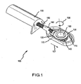
- FIG. 1 representatively illustrates an isometric view of a gear drive system in accordance with an exemplary embodiment of the present invention
- FIG. 2 representatively illustrates a side cross-sectional view of a gear drive system in accordance with an exemplary embodiment of the present invention
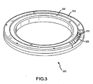
- FIG. 3 representatively illustrates an isometric view of a cross-roller bearing in accordance with an exemplary embodiment of the present invention.
- Various representative implementations of the present invention may be applied to any gear drive system.
- Certain representative implementations may include, for example, missile fin controls.
- the terms "rack”. "pinion”, “gear” or any variation or combination thereof, are generally intended to include anything that may be characterized as elements of a gear and/or gear system.
- FIG. 1 representatively illustrates an isometric view of a gear drive system 100 in accordance with an exemplary embodiment of the present invention.
- Gear drive system 100 may include a rock 110 having an inner surface 115 with a tuck gear 120 disposed on one side of the inner surface 115.
- Rack gear 120 may be engaged with a pinion 130 having a pinion gear 140.
- a ball screw 150 may be engaged both with the ball nut 160 of the rack 110 and with a motor 170.
- the motor 170 may rotate the ball screw 150, and the engagement of the ball nut 160 with the ball screw 150 may move the rack 110 with a linear motion 107 along the length of ball screw 150.
- the linear motion 107 of the rack may impart a rotational motion 108 to the pinion 130 at the pinion gear 140 and the rack gear 120 engage.
- An output shaft 180 may he coupled to pinion 130.
- Output shaft 180 may be coupled to impart a torque to an external device, structure, assembly, and/or the like.
- the gear drive system 100 shown may be used for any purpose where linear motion 107 may be translated to rotational motion 108 or where rotational motion 108 may be translated to linear motion 107.
- Rack 110 may interface with pinion 130 in any suitable manner.
- the pinion 130 may be disposed within the structure of the rack 110 and the pinion 130 may rotate in response to the movement of rack 110.
- Rack 110 may include any appropriate system, structure, and/or device to engage pinion 130.
- rack 110 may include a rack gear 120 which comprises gear teeth partially along a portion of the inner surface 115 of one side of the rack 110.
- pinion 130 may include u pinion gear 140 comprising gear teeth at least partially along the outer surface of pinion 130.
- Rack gear 120 suitably meshes with the pinion gear 140 of pinion 130 such that pinion 130 rotates as the rack 110 moves.
- Pinion 130 may interface with any other suitable structures, devices, and/or systems in any configuration and in any suitable manner.
- pinion 130 may interface with output shaft 180 to operate the fin of a missile.
- Rack 110 may include any other suitable systems, structures and devices.
- rack 110 includes a ball nut 160 that interface with ball screw 150 to allow rack 110 to move at least partially along hall screw 150 in response to rotation of ball screw 150.
- Ball screw 150 may comprise any suitable structures, systems and/or devices in any configuration.
- ball screw 150 in the present embodiment comprises a threaded shaft.
- Ball screw 150 may alternatively, conjunctively or sequentially include any appropriate structure, system and/or device to suitably drive rack 110.
- Ball nut 160 may be configured in any suitable manner to interface with ball screw 150, such as including a threaded surface suitably adapted to engage the threads on ball screw 150.
- Ball nut 160 may comprise any other structure, system and/or device that may be suitably configured to permit rack 110 to engage ball screw 150.
- Ball screw 150 may interface with any suitable system, such as motor 170.
- motor 170 may drive ball screw 150 to cause rack 110 to move along the length of ball screw 150.
- Motor 170 may comprise any suitable structure, system and/or device suitably adapted to move the bull screw 150, such as an electric motor, or any other drive mechanism, whether now known or subsequently described in the art.
- Rack 110 may he of any suitable size, shape, geometry and/or symmetry to achieve any purpose.
- gear drive system 100 may be configured to provide a low profile for use in controlling, for example, the fins of a missile.
- Gear drive system 100 may at least partially limit its profile with the disposition of pinion 130 substantially within the structure of rack 110.
- FIG. 2 representatively illustrates a side cross-sectional view of a gear drive system 100 in accordance with an exemplary embodiment of the present invention.
- at least one stabilizer bearing 210 may engage the structure of rack 110 in any suitable manner to substantially react to the separating forces generated by engagement of rack gear 120 and pinion gear 140 in order to prevent or otherwise obstruct rack gear 120 and pinion gear 140 from disengaging.
- Stabilizer bearing 210 may interface with any other suitable structures, systems, and/or devices to suitably respond to any forces generated inside or outside the gear drive system 100.
- rack gear 120 and pinion gear 140 may be adapted to substantially mash on one side of rack 110 via rack gear 120 and pinion gear 140.
- Stabilizer bearing 210 may suitably engage with rack 110 on the opposite side of rack 110 from rack gear 120 to react to the separating force generated by engagement of rack gear 120 and pinion gear 140, in order to substantially prevent or otherwise obstruct rack gear 120 and pinion gear 140 from disengaging.
- Stabilizer hearing 210 may comprise means for redirecting gear separation load back to pinion gear 140 via rack 110 directly. This allows the rack to maintain a relatively small aspect ratio without outboard bearing arrangements that typically increase the sectional area of gear drive system 100.
- Stabilizer hearing 210 may comprise any suitable structures, devices and/or systems in any configuration.
- stabilizer bearing 210 may comprise at least one of a cross roller hearing 220 and a ball bearing 215.
- Stabilizer bearing 210 may be used in the gear drive system 100 to achieve any other suitable purpose, such as maintaining the alignment of rack gear 120 and pinion gear 140.
- Stabilizer bearing 210 may be used to provide an appropriate amount of stiffness against axial and lateral loads, as well as bending moments that may be generated by operation of the gear drive system 100.
- Stabilizer bearing 210 may be used to react to multiple load vectors for any suitable purpose, such as to reduce the number of stabilizer bearings 210 in a gear drive system 100 and allow gear drive system 100 to be implemented with fewer parts, allowing a low-cost and low-profile packaging arrangement.
- a ball bearing 215 is a common type of rolling-element bearing.
- Ball bearing 215 may comprise a bearing assembly in which a surface moves upon loose hardened steel balls that roll easily in a cage. In ball bearings, the friction of sliding motion is minimized through the use of a low-friction rolling motion.
- An array of spherical balls may be held between V-grooves or rails with a cage that prevents adjacent balls from touching one another. To minimize wobble, the rails may be forcefully preloaded to apply pressure uniformly along the bearing.
- Ball bearings 215 may support both axial and radial loads and may tolerate some misalignment of the inner and outer races. Also, balls in ball bearings 215 are relatively easy to manufacture, compared to other kinds of rolling elements. Ball bearings tend to have lower loud capacity for their size than other kinds of rolling-element bearings. There are several common designs of ball bearings, each offering various tradeoffs.
- a radial ball bearing uses axially symmetric inner and outer races that are shaped to transmit a radial load passes radially through the bearing. Most radial designs also support modest axial loads.
- An angular contact ball bearing uses axially asymmetric races. An angular load generally passes in a straight line through the bearing, whereas a radial load takes an oblique path that tends to separate the races axially. The angle of contact on the inner race is typically the same as that on the outer race.
- Angular contact bearings allow combined toads ( i . e ., loading in both the radial and axial directions) and the contact angle of the bearing may he matched to the relative proportions of each. The larger the contact angle (typically in the range 10 to 45 degrees), the higher the axial load supported, but the lower the radial load.
- An axial ball bearing generally uses side-by-side races. An axial load is transmitted substantially directly through the bearing, while a radial load is poorly-supported ( i . e ., tends to separate the races), with anything other than a small radial load being likely to damage the bearing.
- a deep-groove radial bearing is one in which the race dimensions are close to the dimensions of the balls that run in it. Deep-groove bearings have higher load ratings for their size than shallow-groove bearings, but are also less tolerant of misalignment of the inner and outer races. A misaligned shallow-groove bearing may support a larger load than a similar deep-groove bearing with similar misalignment.
- Ball hearing 215 is not limited to the types of ball bearings recited vide supra and may include any type and/or size of ball bearing.
- FIG. 3 representatively illustrates an isometric view of a cross-roller bearing 220 in accordance with an exemplary embodiment of the present invention.
- Cross-roller bearing 220 may comprise a bearing assembly where the bearing surface moves upon loose, hardened, cylindrical rollers 315, oriented at 90-degree angles to each other that role freely in a cage.
- the cage may include an inner ring 305 and an outer ring 310.
- Cross-roller hearing 220 is similar to ball bearing 215 except that the balls are replaced with small steel rollers.
- the rollers 315 may be held apart from one another by a spacer retainer 320 to prevent adjacent rollers from touching.
- the stage can be prcloaded and will operate at any angle. Point loading of the ball bearing is changed to a line contact with the cross-roller hearing.
- crossed-roller bearings can have a higher preload applied and carry greater loads.
- Stabilizer bearing 210 is not limited to cross-roller bearings and ball bearings 215, and may also comprise any other suitable bearing systems and structures.
- Cross-roller bearing 220 may be used to react to multiple load vectors so as to reduce the number of stabilizer bearings 210 in a gear drive system 100 and allow the gear drive system 100 to be implemented with fewer parts, thereby allowing a low-cost and low-profile packaging arrangement.
- Stabilizer hearing 210 may be used to allow the gear separation load to react back to the pinion gear 140 via the rack 110 directly. This allows the rack to stay small in aspect cross-section, without outboard bearing arrangements that typically increase the sectional area of gear drive system 100.
- the lower sectional urea of gear drive system 100 makes it advantageous for uses where the cross-sectional area of a gear drive system must kept to a minimum, for example, on the outboard structure of missile to control movement for example, of a missile fin.
- any method or process claims may be executed in any order and are not limited to the specific order presented in the claims.
- the components and/or elements recited in any apparatus claims may be assembled or otherwise operationally configured in a variety of permutations to produce substantially the same result as the present invention and are accordingly not limited to the specific configuration recited in the claims.
- the terms “comprising”, “having”, “including” or any contextual variant thereof are intended to reference a non-exclusive inclusion, such that a process, method, article, composition or apparatus that comprises a list of elements does not include only those elements recited, but may also include other elements not expressly listed or inherent to such process, method, article, composition or apparatus.
- Other combinations and/or modifications of the above-described structures, arrangements, applications, proportions, elements, materials or components used in the practice of the present invention, in addition to those not specifically recited, may be varied or otherwise particularly adapted to specific environments, manufacturing specifications, design parameters or other operating requirements without departing from the general principles of the same.
Landscapes
- Engineering & Computer Science (AREA)
- General Engineering & Computer Science (AREA)
- Mechanical Engineering (AREA)
- Physics & Mathematics (AREA)
- Fluid Mechanics (AREA)
- Transmission Devices (AREA)
Abstract
Description
- The present invention generally concerns gear drive systems; and more particularly, representative and exemplary embodiments of the present invention generally relate to systems, devices and methods relating to low-profile rack and pinion gear arrangements, according to the preamble of claims 1, 4.
- Gear drives are used in a wide variety of applications to perform a number of different functions. In some applications, for example, gear drives may be used to change rotational direction and alter rotational speed in a mechanical system. One common application of a gear drive system is a rack and pinion gear system, which converts rotation to linear motion. However, in order for the rack and pinion gears to remain engaged with each other, such systems must typically react to the gear-mesh separation force generated by the mashing of the gear teeth on the rack and pinion gears. Many conventional systems include additional structures that react to the separation force, but which also increase the size of the gear systems, which converts rotary motion to linear motion and vice versa.
-
EP 1 553 327 discloses a gear drive system according to the preamble of claim 1.
There is a need, not met in the conventional art, of a method and apparatus for a rack and pinion gear system that does not require additional, outside structures to counter reaction to the separation forces created through operation of the rack and pinion gear system. - The present invention provides a gear drive system, and method as recited in the claims. The pinion is generally responsive to the movement of the rack.
- Advantages of the present invention will be set forth in the Detailed Description which follows and may be apparent from the Detailed Description or may be learned by practice of exemplary embodiments of the invention. Still other advantages of the invention may be realized by means of any of the instrumentalities, methods or combinations particularly pointed out in the claims.
- Representative elements, operational features, applications and/or advantages of the present invention reside inter alia in the details of construction and operation as more fully hereafter depicted, described and claimed-reference being made to the accompanying drawings forming a part hereof, wherein like numerals refer to like parts throughout. Other elements, operational features, applications and/or advantages will become apparent in light of certain exemplary embodiments recited in the detailed description, wherein:
-
FIG. 1 representatively illustrates an isometric view of a gear drive system in accordance with an exemplary embodiment of the present invention; -
FIG. 2 representatively illustrates a side cross-sectional view of a gear drive system in accordance with an exemplary embodiment of the present invention; and -
FIG. 3 representatively illustrates an isometric view of a cross-roller bearing in accordance with an exemplary embodiment of the present invention. - Elements in the Figures are illustrated for simplicity and clarity and huvc not necessarily been drawn to scale. For example, the dimensions of some of the elements in the Figures may be exaggerated relative to other elements to help improve understanding of various embodiments of the present invention. Furthermore, the terms "first", "second", and the like herein, if any, are used Inter alia for distinguishing between similar elements and not necessarily for describing a sequential or chronological order. Moreover, the terms "front", "back", "top", "bottom" "over", "under", "forward", "aft", and the like in the Description and/or in the claims, if any, are generally employed for descriptive purposes and not necessarily for comprehensively describing exclusive relative position. Any of the preceding terms so used may be interchanged under appropriate circumstances such that various embodiments of the invention described herein, for example, may be capable of operation in other configurations and/or orientations than those explicitly illustrated or otherwise described.
- The following representative descriptions of the present invention generally relate to exemplary embodiments and the inventor's conception of the best mode, and are not intended to limit the scope, applicability or configuration of the invention in any way. Rather, the following description is intended to provide convenient illustrations for implementing various embodiments of the invention. As will become apparent, changes may be made in the function and/or arrangement of any of the elements described in the disclosed exemplary embodiments without departing from the spirit and scope of the invention.
- Various representative implementations of the present invention may be applied to any gear drive system. Certain representative implementations may include, for example, missile fin controls. As used herein, the terms "rack". "pinion", "gear" or any variation or combination thereof, are generally intended to include anything that may be characterized as elements of a gear and/or gear system.
- A detailed description ofan exemplary application, namely a low-profile rack and pinion gear system, is provided as a specific enabling disclosure that may be generalised to any application of the disclosed system, device and method for a gear drive in accordance with various embodiments of the present invention.
-
FIG. 1 representatively illustrates an isometric view of agear drive system 100 in accordance with an exemplary embodiment of the present invention.Gear drive system 100 may include arock 110 having aninner surface 115 with atuck gear 120 disposed on one side of theinner surface 115.Rack gear 120 may be engaged with apinion 130 having apinion gear 140. In this exemplary embodiment, aball screw 150 may be engaged both with theball nut 160 of therack 110 and with amotor 170. Themotor 170 may rotate theball screw 150, and the engagement of theball nut 160 with theball screw 150 may move therack 110 with alinear motion 107 along the length ofball screw 150. Thelinear motion 107 of the rack may impart arotational motion 108 to thepinion 130 at thepinion gear 140 and therack gear 120 engage. Anoutput shaft 180 may he coupled topinion 130.Output shaft 180 may be coupled to impart a torque to an external device, structure, assembly, and/or the like. Thegear drive system 100 shown may be used for any purpose wherelinear motion 107 may be translated torotational motion 108 or whererotational motion 108 may be translated tolinear motion 107. - Rack 110 may interface with
pinion 130 in any suitable manner. For example, thepinion 130 may be disposed within the structure of therack 110 and thepinion 130 may rotate in response to the movement ofrack 110. Rack 110 may include any appropriate system, structure, and/or device to engagepinion 130. In the present exemplary embodiment,rack 110 may include arack gear 120 which comprises gear teeth partially along a portion of theinner surface 115 of one side of therack 110. Also,pinion 130 may includeu pinion gear 140 comprising gear teeth at least partially along the outer surface ofpinion 130.Rack gear 120 suitably meshes with thepinion gear 140 ofpinion 130 such thatpinion 130 rotates as therack 110 moves. Pinion 130 may interface with any other suitable structures, devices, and/or systems in any configuration and in any suitable manner. For example,pinion 130 may interface withoutput shaft 180 to operate the fin of a missile. -
Rack 110 may include any other suitable systems, structures and devices. In the present embodiment, for example,rack 110 includes aball nut 160 that interface withball screw 150 to allowrack 110 to move at least partially alonghall screw 150 in response to rotation ofball screw 150.Ball screw 150 may comprise any suitable structures, systems and/or devices in any configuration. For example,ball screw 150 in the present embodiment comprises a threaded shaft.Ball screw 150 may alternatively, conjunctively or sequentially include any appropriate structure, system and/or device to suitably driverack 110. -
Ball nut 160 may be configured in any suitable manner to interface withball screw 150, such as including a threaded surface suitably adapted to engage the threads onball screw 150.Ball nut 160 may comprise any other structure, system and/or device that may be suitably configured to permitrack 110 to engageball screw 150.Ball screw 150 may interface with any suitable system, such asmotor 170. In the present exemplary embodiment,motor 170 may driveball screw 150 to causerack 110 to move along the length ofball screw 150.Motor 170 may comprise any suitable structure, system and/or device suitably adapted to move thebull screw 150, such as an electric motor, or any other drive mechanism, whether now known or subsequently described in the art. -
Rack 110 may he of any suitable size, shape, geometry and/or symmetry to achieve any purpose. In the present exemplary embodiment,gear drive system 100 may be configured to provide a low profile for use in controlling, for example, the fins of a missile.Gear drive system 100 may at least partially limit its profile with the disposition ofpinion 130 substantially within the structure ofrack 110. -
FIG. 2 representatively illustrates a side cross-sectional view of agear drive system 100 in accordance with an exemplary embodiment of the present invention. In a representative embodiment, at least onestabilizer bearing 210 may engage the structure ofrack 110 in any suitable manner to substantially react to the separating forces generated by engagement ofrack gear 120 andpinion gear 140 in order to prevent or otherwise obstructrack gear 120 andpinion gear 140 from disengaging.Stabilizer bearing 210 may interface with any other suitable structures, systems, and/or devices to suitably respond to any forces generated inside or outside thegear drive system 100. In the present exemplary embodiment,rack gear 120 andpinion gear 140 may be adapted to substantially mash on one side ofrack 110 viarack gear 120 andpinion gear 140.Stabilizer bearing 210 may suitably engage withrack 110 on the opposite side ofrack 110 fromrack gear 120 to react to the separating force generated by engagement ofrack gear 120 andpinion gear 140, in order to substantially prevent or otherwise obstructrack gear 120 andpinion gear 140 from disengaging.Stabilizer hearing 210 may comprise means for redirecting gear separation load back topinion gear 140 viarack 110 directly. This allows the rack to maintain a relatively small aspect ratio without outboard bearing arrangements that typically increase the sectional area ofgear drive system 100. -
Stabilizer hearing 210 may comprise any suitable structures, devices and/or systems in any configuration. In the present embodiment, for example, stabilizer bearing 210 may comprise at least one of across roller hearing 220 and aball bearing 215.Stabilizer bearing 210 may be used in thegear drive system 100 to achieve any other suitable purpose, such as maintaining the alignment ofrack gear 120 andpinion gear 140.Stabilizer bearing 210 may be used to provide an appropriate amount of stiffness against axial and lateral loads, as well as bending moments that may be generated by operation of thegear drive system 100.Stabilizer bearing 210 may be used to react to multiple load vectors for any suitable purpose, such as to reduce the number ofstabilizer bearings 210 in agear drive system 100 and allowgear drive system 100 to be implemented with fewer parts, allowing a low-cost and low-profile packaging arrangement. - A
ball bearing 215 is a common type of rolling-element bearing.Ball bearing 215 may comprise a bearing assembly in which a surface moves upon loose hardened steel balls that roll easily in a cage. In ball bearings, the friction of sliding motion is minimized through the use of a low-friction rolling motion. An array of spherical balls may be held between V-grooves or rails with a cage that prevents adjacent balls from touching one another. To minimize wobble, the rails may be forcefully preloaded to apply pressure uniformly along the bearing. -
Ball bearings 215 may support both axial and radial loads and may tolerate some misalignment of the inner and outer races. Also, balls inball bearings 215 are relatively easy to manufacture, compared to other kinds of rolling elements. Ball bearings tend to have lower loud capacity for their size than other kinds of rolling-element bearings. There are several common designs of ball bearings, each offering various tradeoffs. - A radial ball bearing uses axially symmetric inner and outer races that are shaped to transmit a radial load passes radially through the bearing. Most radial designs also support modest axial loads. An angular contact ball bearing uses axially asymmetric races. An angular load generally passes in a straight line through the bearing, whereas a radial load takes an oblique path that tends to separate the races axially. The angle of contact on the inner race is typically the same as that on the outer race. Angular contact bearings allow combined toads (i.e., loading in both the radial and axial directions) and the contact angle of the bearing may he matched to the relative proportions of each. The larger the contact angle (typically in the range 10 to 45 degrees), the higher the axial load supported, but the lower the radial load.
- An axial ball bearing generally uses side-by-side races. An axial load is transmitted substantially directly through the bearing, while a radial load is poorly-supported (i.e., tends to separate the races), with anything other than a small radial load being likely to damage the bearing. A deep-groove radial bearing is one in which the race dimensions are close to the dimensions of the balls that run in it. Deep-groove bearings have higher load ratings for their size than shallow-groove bearings, but are also less tolerant of misalignment of the inner and outer races. A misaligned shallow-groove bearing may support a larger load than a similar deep-groove bearing with similar misalignment.
Ball hearing 215 is not limited to the types of ball bearings recited vide supra and may include any type and/or size of ball bearing. -
FIG. 3 representatively illustrates an isometric view of across-roller bearing 220 in accordance with an exemplary embodiment of the present invention.Cross-roller bearing 220 may comprise a bearing assembly where the bearing surface moves upon loose, hardened,cylindrical rollers 315, oriented at 90-degree angles to each other that role freely in a cage. The cage may include aninner ring 305 and anouter ring 310.Cross-roller hearing 220 is similar toball bearing 215 except that the balls are replaced with small steel rollers. Therollers 315 may be held apart from one another by aspacer retainer 320 to prevent adjacent rollers from touching. By having the axis of rotation alternate or cross at 90 degrees, the stage can be prcloaded and will operate at any angle. Point loading of the ball bearing is changed to a line contact with the cross-roller hearing. Thus, because of the large load-bearing surfaces, crossed-roller bearings can have a higher preload applied and carry greater loads. -
Stabilizer bearing 210 is not limited to cross-roller bearings andball bearings 215, and may also comprise any other suitable bearing systems and structures.Cross-roller bearing 220 may be used to react to multiple load vectors so as to reduce the number ofstabilizer bearings 210 in agear drive system 100 and allow thegear drive system 100 to be implemented with fewer parts, thereby allowing a low-cost and low-profile packaging arrangement.Stabilizer hearing 210 may be used to allow the gear separation load to react back to thepinion gear 140 via therack 110 directly. This allows the rack to stay small in aspect cross-section, without outboard bearing arrangements that typically increase the sectional area ofgear drive system 100. The lower sectional urea ofgear drive system 100 makes it advantageous for uses where the cross-sectional area of a gear drive system must kept to a minimum, for example, on the outboard structure of missile to control movement for example, of a missile fin. - In the foregoing specification, the invention has been described with reference to specific exemplary embodiments; however, it will be appreciated that various modifications and changes may be made without departing from the scope of the present invention as set forth in the claims below. The specification and figures are to be regarded in an illustrative manner, rather than a restrictive one and all such modifications are intended to be included within the scope of the present invention. Accordingly, the scope of the invention should be determined by the claims appended hereto and their legal equivalents rather than by merely the examples described above.
- For example, the steps recited in any method or process claims may be executed in any order and are not limited to the specific order presented in the claims. Additionally, the components and/or elements recited in any apparatus claims may be assembled or otherwise operationally configured in a variety of permutations to produce substantially the same result as the present invention and are accordingly not limited to the specific configuration recited in the claims.
- Benefits, other advantages and solutions to problems have been described above with regard to particular embodiments; however, any benefit, advantage, solution to problem or any element that may cause any particular benefit, advantage or solution to occur or to become more pronounced are not to be construed as critical, required or essential features or component of any or all the claims.
- As used herein, the terms "comprising", "having", "including" or any contextual variant thereof, are intended to reference a non-exclusive inclusion, such that a process, method, article, composition or apparatus that comprises a list of elements does not include only those elements recited, but may also include other elements not expressly listed or inherent to such process, method, article, composition or apparatus. Other combinations and/or modifications of the above-described structures, arrangements, applications, proportions, elements, materials or components used in the practice of the present invention, in addition to those not specifically recited, may be varied or otherwise particularly adapted to specific environments, manufacturing specifications, design parameters or other operating requirements without departing from the general principles of the same.
Claims (16)
- A gear drive system (100) comprising:a rack (110) having an inner surface (115) and a rack gear (120) disposed on the inner surface (115);a pinion (130) having a pinion gear (140) coupled to engage the rack gear (120); and characterised by:at least one stabilizer bearing (210) coupled to engage the rack (110) and the pinion (130), wherein the stabilizer bearing (210) is movably coupled to the inner surface (115) of the rack (110), and wherein the stabilizer bearing (210) is coupled to react to separating forces generated by engagement of the rack gear (120) and the pinion gear (140).
- The gear drive system (100) of claim 1, wherein the rack (110) comprises a ball nut (160), and wherein the gear drive system (100) further comprises a ball screw (150) coupled to threadably engage said ball nut (160).
- The gear drive system (100) of claim 1, further comprising an output shaft (180) coupled to the pinion (130).
- A method for actuating a gear drive system (100), said method comprising the steps of:providing a rack (110) having an inner surface (115) and a rack gear (120) disposed on the inner surface (115);providing a pinion (130) having a pinion gear (140) coupled to engage the rack gear (120); characterised by:providing at least one stabilizer bearing (210) coupled to engage the rack (110) and the pinion (130), wherein the stabilizer bearing (210) is movably coupled to the inner surface (115) of the rack (110); andimparting a linear motion to the rack (110), wherein the linear motion imparts a rotational motion to the pinion (130), wherein the stabilizer bearing (210) is coupled to react to separating forces generated by the linear motion of the rack (110) and the rotational motion of the pinion (130).
- The method of claim 4, wherein the stabilizer bearing (210) maintains alignment of at least one of the rack gear (120) and the pinion gear (140).
- The method of claim 4, wherein the at least one stabilizer bearing (210) comprises at least one of a cross-roller bearing (220) and a ball bearing (215).
- The method of claim 4, wherein the rack (110) comprises a ball nut (160), and further comprising the step of providing a ball screw (150) coupled to threadably engage the ball nut (160).
- The method of claim 7, further comprising the step of providing a motor (170), wherein the motor (170) is coupled to rotate the ball screw (150) to impart the linear motion to the rack (110).
- The method of claim 8, wherein the linear motion of the rack (110) is coupled to impart the rotational motion to the pinion (130).
- The method of claim 4, wherein rotational motion of the pinion (130) imparts a torque to an output shaft (180) coupled to the pinion (130).
- The gear drive system (100) of claim 1, wherein
the rack (110) comprises:a ball nut (160); andthe pinion (130) is coupled to the inner surface of the rack (110). - The gear drive system (100) of claim 1 or claim 11, wherein the stabilizer bearing (210) is coupled to maintain alignment of at least one of the rack gear (120) and the pinion gear (140).
- The gear drive system (100) of claim 1 or claim 11, wherein the stabilizer bearing (210) comprises at least one of a cross-roller bearing (220) and a ball bearing (215).
- The gear drive system (100) of claim 11, further comprising a ball screw (150) coupled to threadably engage the ball nut (160).
- The gear drive system (100) of claim 2 or claim 14, further comprising a motor (180), wherein the motor (180) is coupled to rotate the ball screw (150) to impart a linear motion to the rack (110).
- The gear drive system (100) of claim 15, wherein the linear motion of the rack (110) is coupled to impart a rotational motion to the pinion (130).
Applications Claiming Priority (2)
| Application Number | Priority Date | Filing Date | Title |
|---|---|---|---|
| US11/277,547 US7765885B2 (en) | 2006-03-27 | 2006-03-27 | Gear drive system and method |
| PCT/US2007/064889 WO2007112331A2 (en) | 2006-03-27 | 2007-03-26 | Gear drive system and method |
Publications (3)
| Publication Number | Publication Date |
|---|---|
| EP1999004A2 EP1999004A2 (en) | 2008-12-10 |
| EP1999004A4 EP1999004A4 (en) | 2009-04-29 |
| EP1999004B1 true EP1999004B1 (en) | 2010-11-24 |
Family
ID=38531939
Family Applications (1)
| Application Number | Title | Priority Date | Filing Date |
|---|---|---|---|
| EP07759345A Active EP1999004B1 (en) | 2006-03-27 | 2007-03-26 | Gear drive system and method |
Country Status (4)
| Country | Link |
|---|---|
| US (1) | US7765885B2 (en) |
| EP (1) | EP1999004B1 (en) |
| DE (1) | DE602007010742D1 (en) |
| WO (1) | WO2007112331A2 (en) |
Families Citing this family (1)
| Publication number | Priority date | Publication date | Assignee | Title |
|---|---|---|---|---|
| US8530809B2 (en) | 2011-08-03 | 2013-09-10 | Raytheon Company | Ring gear control actuation system for air-breathing rocket motors |
Family Cites Families (10)
| Publication number | Priority date | Publication date | Assignee | Title |
|---|---|---|---|---|
| US27307A (en) * | 1860-02-28 | Convebtibtg reciprocating into eotary motion | ||
| US3688374A (en) * | 1970-10-23 | 1972-09-05 | Cam Gears Ltd | Method of making an integral pinion and inner bearing race for rack and pinion assembly |
| US3777590A (en) * | 1972-05-15 | 1973-12-11 | Ford Motor Co | Rack and pinion steering gear |
| AU515182B2 (en) * | 1977-02-09 | 1981-03-19 | Bishop, A.E. | Low friction rack & pinion steering gear |
| US4531603A (en) * | 1984-01-09 | 1985-07-30 | General Motors Corporation | Rack and pinion steering gear with adjustable low friction anti-roll rack bearing |
| US5099714A (en) * | 1991-06-14 | 1992-03-31 | Deere & Company | Rack and pinion steering mechanism |
| US5236398A (en) * | 1992-08-03 | 1993-08-17 | Franklin E. Barnett | Wheelchair drive apparatus |
| JP3452299B2 (en) * | 1997-09-03 | 2003-09-29 | 本田技研工業株式会社 | Electric power steering device |
| US7293626B2 (en) * | 2001-08-01 | 2007-11-13 | Delphi Technologies, Inc. | Apparatus and method for steering a vehicle |
| DE102004001795A1 (en) | 2004-01-06 | 2005-08-11 | Siemens Ag | switching mechanism |
-
2006
- 2006-03-27 US US11/277,547 patent/US7765885B2/en active Active
-
2007
- 2007-03-26 DE DE602007010742T patent/DE602007010742D1/en active Active
- 2007-03-26 WO PCT/US2007/064889 patent/WO2007112331A2/en not_active Ceased
- 2007-03-26 EP EP07759345A patent/EP1999004B1/en active Active
Also Published As
| Publication number | Publication date |
|---|---|
| DE602007010742D1 (en) | 2011-01-05 |
| WO2007112331A3 (en) | 2008-02-21 |
| WO2007112331A2 (en) | 2007-10-04 |
| EP1999004A4 (en) | 2009-04-29 |
| US20070221001A1 (en) | 2007-09-27 |
| US7765885B2 (en) | 2010-08-03 |
| EP1999004A2 (en) | 2008-12-10 |
Similar Documents
| Publication | Publication Date | Title |
|---|---|---|
| US8544357B2 (en) | Differential roller screw | |
| US11561142B2 (en) | Electromechanical actuator with integrated force sensor | |
| EP2180210A1 (en) | Reduction gear | |
| JP4475679B2 (en) | Rolling element screw device | |
| EP3222881B1 (en) | Electric linear actuator and electric brake device | |
| CN110637178B (en) | Anti-backlash device and method | |
| WO2012144371A1 (en) | Linear motion guide mechanism | |
| CN107208713B (en) | Actuator with planetary roller screw drive | |
| JP2011518996A (en) | Angular contact roller bearings, especially double row tandem spherical roller bearings | |
| US20100269618A1 (en) | Power transmission device with bevel gear | |
| EP1339602B1 (en) | Roller screw actuator | |
| US7341525B2 (en) | Linear rolling bearing for the transmission of torques | |
| CN106090165A (en) | Actuator with planetary roller screw drive | |
| EP3073152B1 (en) | Preloaded linear actuator system and a method for controlling a such | |
| JP2008116037A (en) | Electrically-operated actuator | |
| EP0486223B1 (en) | Device for applying braking torque to a shaft | |
| US20070221001A1 (en) | Gear drive system and method | |
| US12304574B1 (en) | Rotation limiting device, and steering device | |
| JP6121760B2 (en) | Electric linear actuator | |
| EP4317745A1 (en) | Ball screw device | |
| WO2002016804A1 (en) | Drive shaft moving device | |
| JP2010090952A (en) | Structure for supporting ball screw shaft | |
| US11353096B2 (en) | Ball screw drive and support bearing for combined vehicle brake system | |
| JP5360559B2 (en) | Electric linear actuator and electric brake device | |
| JP7171687B2 (en) | Strain wave gearing and bearing member for strain wave gearing |
Legal Events
| Date | Code | Title | Description |
|---|---|---|---|
| PUAI | Public reference made under article 153(3) epc to a published international application that has entered the european phase |
Free format text: ORIGINAL CODE: 0009012 |
|
| 17P | Request for examination filed |
Effective date: 20080917 |
|
| AK | Designated contracting states |
Kind code of ref document: A2 Designated state(s): DE FR GB |
|
| DAX | Request for extension of the european patent (deleted) | ||
| RBV | Designated contracting states (corrected) |
Designated state(s): DE FR GB |
|
| A4 | Supplementary search report drawn up and despatched |
Effective date: 20090401 |
|
| GRAP | Despatch of communication of intention to grant a patent |
Free format text: ORIGINAL CODE: EPIDOSNIGR1 |
|
| RIC1 | Information provided on ipc code assigned before grant |
Ipc: F42B 10/64 20060101ALI20100304BHEP Ipc: F16H 19/00 20060101AFI20100304BHEP |
|
| GRAS | Grant fee paid |
Free format text: ORIGINAL CODE: EPIDOSNIGR3 |
|
| GRAA | (expected) grant |
Free format text: ORIGINAL CODE: 0009210 |
|
| AK | Designated contracting states |
Kind code of ref document: B1 Designated state(s): DE FR GB |
|
| REG | Reference to a national code |
Ref country code: GB Ref legal event code: FG4D |
|
| REF | Corresponds to: |
Ref document number: 602007010742 Country of ref document: DE Date of ref document: 20110105 Kind code of ref document: P |
|
| PLBE | No opposition filed within time limit |
Free format text: ORIGINAL CODE: 0009261 |
|
| STAA | Information on the status of an ep patent application or granted ep patent |
Free format text: STATUS: NO OPPOSITION FILED WITHIN TIME LIMIT |
|
| 26N | No opposition filed |
Effective date: 20110825 |
|
| REG | Reference to a national code |
Ref country code: DE Ref legal event code: R097 Ref document number: 602007010742 Country of ref document: DE Effective date: 20110825 |
|
| REG | Reference to a national code |
Ref country code: FR Ref legal event code: PLFP Year of fee payment: 10 |
|
| REG | Reference to a national code |
Ref country code: FR Ref legal event code: PLFP Year of fee payment: 11 |
|
| REG | Reference to a national code |
Ref country code: FR Ref legal event code: PLFP Year of fee payment: 12 |
|
| P01 | Opt-out of the competence of the unified patent court (upc) registered |
Effective date: 20230530 |
|
| PGFP | Annual fee paid to national office [announced via postgrant information from national office to epo] |
Ref country code: DE Payment date: 20250218 Year of fee payment: 19 |
|
| PGFP | Annual fee paid to national office [announced via postgrant information from national office to epo] |
Ref country code: FR Payment date: 20250218 Year of fee payment: 19 |
|
| PGFP | Annual fee paid to national office [announced via postgrant information from national office to epo] |
Ref country code: GB Payment date: 20250221 Year of fee payment: 19 |