EP1998673B1 - Method and apparatus for determining stress in an anatomical structure - Google Patents
Method and apparatus for determining stress in an anatomical structure Download PDFInfo
- Publication number
- EP1998673B1 EP1998673B1 EP07713231.4A EP07713231A EP1998673B1 EP 1998673 B1 EP1998673 B1 EP 1998673B1 EP 07713231 A EP07713231 A EP 07713231A EP 1998673 B1 EP1998673 B1 EP 1998673B1
- Authority
- EP
- European Patent Office
- Prior art keywords
- locations
- stress
- determining
- range
- stiffness
- Prior art date
- Legal status (The legal status is an assumption and is not a legal conclusion. Google has not performed a legal analysis and makes no representation as to the accuracy of the status listed.)
- Not-in-force
Links
Images

Classifications
-
- A—HUMAN NECESSITIES
- A61—MEDICAL OR VETERINARY SCIENCE; HYGIENE
- A61B—DIAGNOSIS; SURGERY; IDENTIFICATION
- A61B6/00—Apparatus or devices for radiation diagnosis; Apparatus or devices for radiation diagnosis combined with radiation therapy equipment
- A61B6/50—Apparatus or devices for radiation diagnosis; Apparatus or devices for radiation diagnosis combined with radiation therapy equipment specially adapted for specific body parts; specially adapted for specific clinical applications
- A61B6/504—Apparatus or devices for radiation diagnosis; Apparatus or devices for radiation diagnosis combined with radiation therapy equipment specially adapted for specific body parts; specially adapted for specific clinical applications for diagnosis of blood vessels, e.g. by angiography
-
- A—HUMAN NECESSITIES
- A61—MEDICAL OR VETERINARY SCIENCE; HYGIENE
- A61B—DIAGNOSIS; SURGERY; IDENTIFICATION
- A61B5/00—Measuring for diagnostic purposes; Identification of persons
- A61B5/02—Detecting, measuring or recording for evaluating the cardiovascular system, e.g. pulse, heart rate, blood pressure or blood flow
- A61B5/02007—Evaluating blood vessel condition, e.g. elasticity, compliance
-
- A—HUMAN NECESSITIES
- A61—MEDICAL OR VETERINARY SCIENCE; HYGIENE
- A61B—DIAGNOSIS; SURGERY; IDENTIFICATION
- A61B6/00—Apparatus or devices for radiation diagnosis; Apparatus or devices for radiation diagnosis combined with radiation therapy equipment
- A61B6/02—Arrangements for diagnosis sequentially in different planes; Stereoscopic radiation diagnosis
- A61B6/03—Computed tomography [CT]
- A61B6/032—Transmission computed tomography [CT]
Definitions
- the present invention relates to method and apparatus for determining stress in an anatomical structure, and relates particularly, but not exclusively, to a method and apparatus for determining stress in a wall of the abdominal aorta in which calcified regions are present.
- AAA abdominal aortic aneurysm
- CTA Computed Tomography Angiography
- AAA's rupture before their diameter reaches 55 mm and a significant percentage of patients that cannot be operated on (for example as a result of cardiac condition) develop a non rupturing AAA with a diameter significantly more than 55 mm (up to 80 mm). It can therefore be seen that the diameter is an inaccurate indicator of rupture risk.
- the peak wall stress in the AAA is a better indicator of rupture risk than the diameter of the AAA. It is known to derive the geometry of the AAA outer wall from CTA images and then assume a wall of constant thickness with constant material properties for the complete AAA. The peak wall stress is then calculated and the position of this peak wall stress on the AAA is determined.
- Preferred embodiments of the present invention seek to overcome the above disadvantages of the prior art.
- the method may use finite-element modeling.
- the method may be a method of determining wall stress in a blood vessel.
- the second locations may correspond to areas of calcification in said blood vessel.
- Said locations are selected by means of a volume mesh.
- Said second stress values may be determined by means of values stored in a memory.
- At least one said processor may be adapted to use finite-element modeling.
- the apparatus may be adapted to determine wall stress in a blood vessel.
- the first locations may correspond to areas of calcification in said blood vessel.
- Said locations are determined by means of a volume mesh.
- Said second stress values may be determined by means of values stored in a memory.
- a data structure for use by a computer system for determining stress in an anatomical structure comprising:
- the data structure maybe executable to use finite-element modeling.
- the data structure may be executable to determine wall stress in a blood vessel.
- the second locations may correspond to areas of calcification in said blood vessel.
- Said locations are determined by means of a volume mesh.
- the third computer code maybe executable to determine said second stress values by means of values stored in a memory.
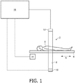
- a medical imaging apparatus 2 embodying the present invention includes a platform 4 for supporting a patient 6 within a circular frame 8 having opposed pairs of x-ray sources 10 and detectors 12 for imaging a patient's heart.
- the platform 4 supporting patient 6 is transported in the direction of arrow A by means of a motor 14, the sources 10, detectors 12 and motor 14 being controlled by a computer 16, which also reconstructs a three dimensional model of the patient's heart from image data obtained by the sources 10 and detectors 12.
- a computer 16 which also reconstructs a three dimensional model of the patient's heart from image data obtained by the sources 10 and detectors 12.
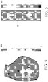
- FIG. 2 a slice of a 3D CTA image of an AAA 18 having calcified regions 20 is shown.
- the AAA outer wall geometry is first automatically segmented by the computer 16, to provide the image shown in Figure 3 , by means of one of more methods which will be familiar to persons skilled in the art.
- First stress values are then determined by assuming uniform stiffness of the AAA shown in Figure 3 , and the wall stress is calculated for a number of locations arranged on a volume mesh, by means of finite-element modeling. This then provides the graphic representation of the peak wall stress as indicated in Figure 4 .
- the primary direction of stress is determined at each of the positions for which the wall stress has been determined.
- the primary direction of stress is the direction of the largest eigenvector of the tensor representing stress.
- the locations of calcified areas are then determined, and the distance, in the primary stress direction, to the closest region of calcification is measured for each location not corresponding to a calcified region.
- This general use table is used to calculate second stress values to take account of calcifications in the arrangement shown in Figures 3 and 4 .
- the process of the present invention has the advantage that a patient-specific finite-element based calculation of the stress in vessel walls with calcified areas can be performed in a few hours on a standard computer, as a result of which the results achieved are as accurate as those of existing methods, but can be obtained much more rapidly.
Landscapes
- Health & Medical Sciences (AREA)
- Life Sciences & Earth Sciences (AREA)
- Medical Informatics (AREA)
- Engineering & Computer Science (AREA)
- Pathology (AREA)
- Public Health (AREA)
- Veterinary Medicine (AREA)
- Biophysics (AREA)
- Physics & Mathematics (AREA)
- General Health & Medical Sciences (AREA)
- Animal Behavior & Ethology (AREA)
- Surgery (AREA)
- Vascular Medicine (AREA)
- Molecular Biology (AREA)
- Biomedical Technology (AREA)
- Heart & Thoracic Surgery (AREA)
- Radiology & Medical Imaging (AREA)
- Optics & Photonics (AREA)
- Nuclear Medicine, Radiotherapy & Molecular Imaging (AREA)
- Dentistry (AREA)
- High Energy & Nuclear Physics (AREA)
- Oral & Maxillofacial Surgery (AREA)
- Cardiology (AREA)
- Physiology (AREA)
- Apparatus For Radiation Diagnosis (AREA)
- Ultra Sonic Daignosis Equipment (AREA)
Description
- The present invention relates to method and apparatus for determining stress in an anatomical structure, and relates particularly, but not exclusively, to a method and apparatus for determining stress in a wall of the abdominal aorta in which calcified regions are present.
- Medical diagnosis of vascular diseases and therapeutic decisions are primarily based on the anatomy and morphology of diseased blood vessels, information about which is derived from medical images. For example, the diagnosis of abdominal aortic aneurysm (AAA), which is dilatation of the abdominal aorta and usually leads directly to death when it ruptures, and the decision to perform surgical repair, is based on the diameter of the AAA. This is usually measured on the basis of ultrasound and/or Computed Tomography Angiography (CTA) images. Intervention is usually performed if the diameter is more than 55 mm.
- However, a small but significant percentage of AAA's rupture before their diameter reaches 55 mm, and a significant percentage of patients that cannot be operated on (for example as a result of cardiac condition) develop a non rupturing AAA with a diameter significantly more than 55 mm (up to 80 mm). It can therefore be seen that the diameter is an inaccurate indicator of rupture risk.
- It has been found that the peak wall stress in the AAA is a better indicator of rupture risk than the diameter of the AAA. It is known to derive the geometry of the AAA outer wall from CTA images and then assume a wall of constant thickness with constant material properties for the complete AAA. The peak wall stress is then calculated and the position of this peak wall stress on the AAA is determined.
- This known method suffers from the disadvantage that it does not use patient-specific wall material properties and wall thickness, which limits the accuracy of the results achieved. Attempts have also been made to incorporate the effect of calcifications in the vessel wall, but this approach does not accurately represent the geometry of the calcifications. Also, since calcifications generally have complex shapes and may be small in relation to the AAA Structures, accurate geometric modeling of these calcifications leads to computationally complex numerical models.
- The reference de Putter S, van de Vosse F N, Breeuwer M, Gerritsen F A, "Local influence of calcifications on the wall mechanics of abdominal aortic aneurysm," Proceedings of the SPIE 6143, pp. 1-11, 2006 describes a determination of the stress in vessel walls with calcified areas.
- Preferred embodiments of the present invention seek to overcome the above disadvantages of the prior art.
- According to an aspect of the present invention, there is provided a method of determining stress in an anatomical structure as defined in claim 1
- By calculating first stress values on the basis of the structure having stiffness in a first range, and then calculating second stress values corrected to take into account regions of stiffness in a second range different from the first range, this enables patient-specific first stress values, and more general second stress values to be calculated. For example, in the case of AAAs, this enables patient-specific first stress values based on the first stiffness range to be calculated, and then second stress values based on more general corrections to take regions of calcification into account. This provides the advantage of enabling the stress in the aorta wall to be calculated as accurately, but significantly more quickly, than in known methods.
- The method may use finite-element modeling.
- The method may be a method of determining wall stress in a blood vessel.
- The second locations may correspond to areas of calcification in said blood vessel.
- Said locations are selected by means of a volume mesh.
- Said second stress values may be determined by means of values stored in a memory.
- According to another aspect of the present invention, there is provided an apparatus for determining stress in an anatomical structure as defined in
claim 10. - At least one said processor may be adapted to use finite-element modeling.
- The apparatus may be adapted to determine wall stress in a blood vessel.
- The first locations may correspond to areas of calcification in said blood vessel.
- Said locations are determined by means of a volume mesh.
- Said second stress values may be determined by means of values stored in a memory.
According to a further aspect of the present invention, there is provided a data structure for use by a computer system for determining stress in an anatomical structure, the data structure comprising: - first computer code executable to determine, from anatomical image data, respective first stress values at a plurality of locations in said structure as defined in claim 15.
- The data structure maybe executable to use finite-element modeling.
- The data structure may be executable to determine wall stress in a blood vessel.
- The second locations may correspond to areas of calcification in said blood vessel.
- Said locations are determined by means of a volume mesh.
- The third computer code maybe executable to determine said second stress values by means of values stored in a memory.
- A preferred embodiment of the invention will now be described, by way of example only and not in any limitative sense, with reference to the accompanying drawings, in which:
-
Fig. 1 is a schematic representation of a medical imaging apparatus embodying the present invention; -
Fig. 2 is a slice of a 3D Computed Tomography Angiography (CTA) image acquisition of an Abdominal Aortic Aneurysm (AAA) indicating the presence of calcified regions; -
Fig. 3 illustrates automatically segmented AAA outer wall geometry of the AAA ofFig. 2 ; -
Fig. 4 indicates an illustration of peak wall stress for an AAA without taking calcifications into account; and -
Fig. 5 is an illustration of the wall stress induced in the wall of an AAA by a calcification, determined by means of a method embodying the present invention. - Referring to
Figure 1 , amedical imaging apparatus 2 embodying the present invention is disclosed. Theapparatus 2 includes a platform 4 for supporting a patient 6 within acircular frame 8 having opposed pairs ofx-ray sources 10 anddetectors 12 for imaging a patient's heart. The platform 4 supporting patient 6 is transported in the direction of arrow A by means of amotor 14, thesources 10,detectors 12 andmotor 14 being controlled by acomputer 16, which also reconstructs a three dimensional model of the patient's heart from image data obtained by thesources 10 anddetectors 12. This aspect of the operation of theapparatus 2 will be well known to persons skilled in the art and will therefore not be described in further detail. - Referring to
Figure 2 , a slice of a 3D CTA image of anAAA 18 having calcifiedregions 20 is shown. In order to determine the peak wall stress in theAAA 18, the AAA outer wall geometry is first automatically segmented by thecomputer 16, to provide the image shown inFigure 3 , by means of one of more methods which will be familiar to persons skilled in the art. First stress values are then determined by assuming uniform stiffness of the AAA shown inFigure 3 , and the wall stress is calculated for a number of locations arranged on a volume mesh, by means of finite-element modeling. This then provides the graphic representation of the peak wall stress as indicated inFigure 4 . - In order to take account of the effect of the calcified
regions 20 on the wall stress, the primary direction of stress is determined at each of the positions for which the wall stress has been determined. As will be appreciated by persons skilled in the art, in determining wall stress by means of finite element modeling, the primary direction of stress is the direction of the largest eigenvector of the tensor representing stress. - The locations of calcified areas are then determined, and the distance, in the primary stress direction, to the closest region of calcification is measured for each location not corresponding to a calcified region. This enables the additional stress induced by various types of calcification to be determined on the basis of pre-calculated values stored in a table, and as illustrated in
Figure 5 . This general use table is used to calculate second stress values to take account of calcifications in the arrangement shown inFigures 3 and4 . - The process of the present invention has the advantage that a patient-specific finite-element based calculation of the stress in vessel walls with calcified areas can be performed in a few hours on a standard computer, as a result of which the results achieved are as accurate as those of existing methods, but can be obtained much more rapidly.
- It will be appreciated by persons skilled in the art that the above embodiment has been described by way of example only and not in any limitative sense, and that various alterations and modifications are possible without departure from the scope of the invention as defined by the appended claims.
Claims (15)
- A computerised method of determining stress in an anatomical structure, the method comprising:determining, from anatomical image data, respective first stress values at a plurality of locations in said structure, by assuming said structure having stiffness within a first range;determining a plurality of first locations from said plurality of locations, at which the stiffness of said anatomical structure is within a second range different from said first range; anddetermining, at a plurality of second locations from said plurality of locations, said plurality of second locations being different from said plurality of first locations, respective second stress values, representing respective first stress values corrected to take into account said anatomical structure having stiffness in said second range at at least one of said first locations.
- A method according to claim 1, wherein the first stress values are determined by use of finite-element modeling.
- A method according to claim 1, wherein the method is configured to determine wall stress in a blood vessel.
- A method according to claim 3, wherein the first locations correspond to areas of calcification in said blood vessel.
- A method according to claim 1, wherein said plurality of locations are determined by means of a volume mesh, on which the locations are arranged.
- A method according to claim 1, wherein the first stress values are determined by assuming said structure having uniform stiffness.
- A method according to claim 1, wherein the primary direction of stress is determined by determining the direction of the largest eigenvector of a tensor representing stress.
- A method according to claim 1, further comprising
determining the primary direction of stress at said plurality of locations in said structure, and
measuring, for each second location, the distance, in the primary stress direction, to the closest first location, and
determining additional stress in addition to the first stress value at each second location. - A method according to claim 8, wherein the additional stress is determined on the basis of pre-calculated values stored in a table.
- An apparatus for determining stress in an anatomical structure, the apparatus comprising at least one processor for:determining, from anatomical image data, respective first stress values at a plurality of locations in said structure, by assuming said structure having stiffness within a first range;determining a plurality of first locations from said plurality of locations, at which the stiffness of said anatomical structure is within a second range different from said first range; anddetermining, at a plurality of second locations from said plurality of locations, said plurality of second locations being different from said plurality of first locations, respective second stress values, representing respective first stress values corrected to take into account said anatomical structure having stiffness in said second range at at least one of said first locations.
- An apparatus according to claim 7, wherein at least one said processor is adapted to determine first stress values by use finite-element modeling.
- An apparatus according to claim 7, wherein the apparatus is adapted to determine wall stress in a blood vessel.
- An apparatus according to claim 9, wherein the first locations correspond to areas of calcification in said blood vessel.
- An apparatus according to claim 7, wherein said plurality of locations are determined by means of a volume mesh, on which the locations are arranged.
- A data structure for use by a computer system for determining stress in an anatomical structure, the data structure comprising:first computer code executable to determine, from anatomical image data, respective first stress values at a plurality of locations in said structure, by assuming said structure having stiffness within a first range;second computer code executable to determine a plurality of first locations from said plurality of locations, at which the stiffness of said anatomical structure is within a second range different from said first range; andthird computer code executable to determine, at a plurality of second locations from said plurality of locations, said plurality of second locations being different from said plurality of first locations, respective second stress values, representing respective first stress values corrected to take into account said anatomical structure having stiffness in said second range at at least one of said first locations.
Priority Applications (1)
| Application Number | Priority Date | Filing Date | Title |
|---|---|---|---|
| EP07713231.4A EP1998673B1 (en) | 2006-03-17 | 2007-03-09 | Method and apparatus for determining stress in an anatomical structure |
Applications Claiming Priority (3)
| Application Number | Priority Date | Filing Date | Title |
|---|---|---|---|
| EP06111323 | 2006-03-17 | ||
| PCT/IB2007/050791 WO2007107904A2 (en) | 2006-03-17 | 2007-03-09 | Method and apparatus for determining stress in an anatomical structure |
| EP07713231.4A EP1998673B1 (en) | 2006-03-17 | 2007-03-09 | Method and apparatus for determining stress in an anatomical structure |
Publications (2)
| Publication Number | Publication Date |
|---|---|
| EP1998673A2 EP1998673A2 (en) | 2008-12-10 |
| EP1998673B1 true EP1998673B1 (en) | 2017-02-22 |
Family
ID=38522813
Family Applications (1)
| Application Number | Title | Priority Date | Filing Date |
|---|---|---|---|
| EP07713231.4A Not-in-force EP1998673B1 (en) | 2006-03-17 | 2007-03-09 | Method and apparatus for determining stress in an anatomical structure |
Country Status (5)
| Country | Link |
|---|---|
| US (1) | US8150117B2 (en) |
| EP (1) | EP1998673B1 (en) |
| JP (1) | JP5275049B2 (en) |
| CN (1) | CN101400304A (en) |
| WO (1) | WO2007107904A2 (en) |
Families Citing this family (3)
| Publication number | Priority date | Publication date | Assignee | Title |
|---|---|---|---|---|
| WO2009049681A1 (en) * | 2007-10-19 | 2009-04-23 | Vascops | Automatic geometrical and mechanical analyzing method and system for tubular structures |
| US9241639B2 (en) | 2010-04-20 | 2016-01-26 | Takumi Washio | System for estimating membrane stress on arbitrarily-shaped curvilinear surface based on current configuration data |
| BR112013001417A2 (en) | 2010-07-21 | 2016-05-24 | Koninkl Philips Electronics Nv | device for testing an individual for detecting a condition of an individual's vascular pathology and method for testing an individual for detecting a state of an individual's vascular pathology |
Family Cites Families (1)
| Publication number | Priority date | Publication date | Assignee | Title |
|---|---|---|---|---|
| JP2008510499A (en) * | 2004-06-23 | 2008-04-10 | エムツーエス・インコーポレーテッド | Anatomical visualization / measurement system |
-
2007
- 2007-03-09 WO PCT/IB2007/050791 patent/WO2007107904A2/en not_active Ceased
- 2007-03-09 EP EP07713231.4A patent/EP1998673B1/en not_active Not-in-force
- 2007-03-09 US US12/293,105 patent/US8150117B2/en active Active
- 2007-03-09 JP JP2008558963A patent/JP5275049B2/en not_active Expired - Fee Related
- 2007-03-09 CN CNA2007800091992A patent/CN101400304A/en active Pending
Non-Patent Citations (1)
| Title |
|---|
| None * |
Also Published As
| Publication number | Publication date |
|---|---|
| CN101400304A (en) | 2009-04-01 |
| US8150117B2 (en) | 2012-04-03 |
| JP2009529944A (en) | 2009-08-27 |
| WO2007107904A3 (en) | 2008-07-03 |
| US20090129645A1 (en) | 2009-05-21 |
| JP5275049B2 (en) | 2013-08-28 |
| WO2007107904A2 (en) | 2007-09-27 |
| EP1998673A2 (en) | 2008-12-10 |
Similar Documents
| Publication | Publication Date | Title |
|---|---|---|
| EP3125764B1 (en) | Processing apparatus for processing cardiac data of a living being | |
| US12377609B2 (en) | Fenestration template for endovascular repair of aortic aneurysms | |
| EP3847956B1 (en) | Method and device for obtaining blood vessel pressure difference | |
| EP3041414B1 (en) | Processing apparatus for processing cardiac data | |
| EP3518751B1 (en) | Apparatus for determining a functional index for stenosis assessment | |
| JP4974887B2 (en) | Image processing system for displaying information relating to parameters of a 3D tubular object | |
| EP3606433B1 (en) | Standardized coronary artery disease metric | |
| EP2925216B1 (en) | Stenosis therapy planning | |
| EP2074589A2 (en) | Spatial characterization of a structure located within an object by identifying 2d representations of the structure within section planes | |
| JP2012115635A (en) | Image processing method, image processing apparatus, imaging system, and program code | |
| EP3512416B1 (en) | Apparatus and method for determining a fractional flow reserve | |
| US10779889B2 (en) | Planning support during an interventional procedure | |
| US8150117B2 (en) | Method and apparatus for determining stress in an anatomical structure | |
| US20250006378A1 (en) | System and method for evaluating a cardiac region of a subject | |
| Brekken et al. | Registration of real-time 3-D ultrasound to tomographic images of the abdominal aorta | |
| EP3447734A1 (en) | Method for creating a pseudo ct image | |
| Friesen et al. | Commentary: Are we there yet? |
Legal Events
| Date | Code | Title | Description |
|---|---|---|---|
| PUAI | Public reference made under article 153(3) epc to a published international application that has entered the european phase |
Free format text: ORIGINAL CODE: 0009012 |
|
| AK | Designated contracting states |
Kind code of ref document: A2 Designated state(s): AT BE BG CH CY CZ DE DK EE ES FI FR GB GR HU IE IS IT LI LT LU LV MC MT NL PL PT RO SE SI SK TR |
|
| AX | Request for extension of the european patent |
Extension state: AL BA HR MK RS |
|
| 17P | Request for examination filed |
Effective date: 20090105 |
|
| RBV | Designated contracting states (corrected) |
Designated state(s): AT BE BG CH CY CZ DE DK EE ES FI FR GB GR HU IE IS IT LI LT LU LV MC MT NL PL PT RO SE SI SK TR |
|
| 17Q | First examination report despatched |
Effective date: 20090225 |
|
| DAX | Request for extension of the european patent (deleted) | ||
| RAP1 | Party data changed (applicant data changed or rights of an application transferred) |
Owner name: KONINKLIJKE PHILIPS N.V. |
|
| GRAP | Despatch of communication of intention to grant a patent |
Free format text: ORIGINAL CODE: EPIDOSNIGR1 |
|
| INTG | Intention to grant announced |
Effective date: 20160902 |
|
| GRAS | Grant fee paid |
Free format text: ORIGINAL CODE: EPIDOSNIGR3 |
|
| GRAA | (expected) grant |
Free format text: ORIGINAL CODE: 0009210 |
|
| AK | Designated contracting states |
Kind code of ref document: B1 Designated state(s): AT BE BG CH CY CZ DE DK EE ES FI FR GB GR HU IE IS IT LI LT LU LV MC MT NL PL PT RO SE SI SK TR |
|
| REG | Reference to a national code |
Ref country code: GB Ref legal event code: FG4D |
|
| REG | Reference to a national code |
Ref country code: CH Ref legal event code: EP |
|
| REG | Reference to a national code |
Ref country code: AT Ref legal event code: REF Ref document number: 868651 Country of ref document: AT Kind code of ref document: T Effective date: 20170315 |
|
| REG | Reference to a national code |
Ref country code: IE Ref legal event code: FG4D |
|
| REG | Reference to a national code |
Ref country code: FR Ref legal event code: PLFP Year of fee payment: 11 |
|
| REG | Reference to a national code |
Ref country code: DE Ref legal event code: R096 Ref document number: 602007049856 Country of ref document: DE |
|
| REG | Reference to a national code |
Ref country code: DE Ref legal event code: R084 Ref document number: 602007049856 Country of ref document: DE |
|
| REG | Reference to a national code |
Ref country code: GB Ref legal event code: 746 Effective date: 20170419 |
|
| REG | Reference to a national code |
Ref country code: LT Ref legal event code: MG4D |
|
| REG | Reference to a national code |
Ref country code: NL Ref legal event code: MP Effective date: 20170222 |
|
| REG | Reference to a national code |
Ref country code: AT Ref legal event code: MK05 Ref document number: 868651 Country of ref document: AT Kind code of ref document: T Effective date: 20170222 |
|
| PG25 | Lapsed in a contracting state [announced via postgrant information from national office to epo] |
Ref country code: LT Free format text: LAPSE BECAUSE OF FAILURE TO SUBMIT A TRANSLATION OF THE DESCRIPTION OR TO PAY THE FEE WITHIN THE PRESCRIBED TIME-LIMIT Effective date: 20170222 Ref country code: GR Free format text: LAPSE BECAUSE OF FAILURE TO SUBMIT A TRANSLATION OF THE DESCRIPTION OR TO PAY THE FEE WITHIN THE PRESCRIBED TIME-LIMIT Effective date: 20170523 Ref country code: FI Free format text: LAPSE BECAUSE OF FAILURE TO SUBMIT A TRANSLATION OF THE DESCRIPTION OR TO PAY THE FEE WITHIN THE PRESCRIBED TIME-LIMIT Effective date: 20170222 |
|
| PG25 | Lapsed in a contracting state [announced via postgrant information from national office to epo] |
Ref country code: PT Free format text: LAPSE BECAUSE OF FAILURE TO SUBMIT A TRANSLATION OF THE DESCRIPTION OR TO PAY THE FEE WITHIN THE PRESCRIBED TIME-LIMIT Effective date: 20170622 Ref country code: LV Free format text: LAPSE BECAUSE OF FAILURE TO SUBMIT A TRANSLATION OF THE DESCRIPTION OR TO PAY THE FEE WITHIN THE PRESCRIBED TIME-LIMIT Effective date: 20170222 Ref country code: NL Free format text: LAPSE BECAUSE OF FAILURE TO SUBMIT A TRANSLATION OF THE DESCRIPTION OR TO PAY THE FEE WITHIN THE PRESCRIBED TIME-LIMIT Effective date: 20170222 Ref country code: BG Free format text: LAPSE BECAUSE OF FAILURE TO SUBMIT A TRANSLATION OF THE DESCRIPTION OR TO PAY THE FEE WITHIN THE PRESCRIBED TIME-LIMIT Effective date: 20170522 Ref country code: SE Free format text: LAPSE BECAUSE OF FAILURE TO SUBMIT A TRANSLATION OF THE DESCRIPTION OR TO PAY THE FEE WITHIN THE PRESCRIBED TIME-LIMIT Effective date: 20170222 Ref country code: ES Free format text: LAPSE BECAUSE OF FAILURE TO SUBMIT A TRANSLATION OF THE DESCRIPTION OR TO PAY THE FEE WITHIN THE PRESCRIBED TIME-LIMIT Effective date: 20170222 Ref country code: AT Free format text: LAPSE BECAUSE OF FAILURE TO SUBMIT A TRANSLATION OF THE DESCRIPTION OR TO PAY THE FEE WITHIN THE PRESCRIBED TIME-LIMIT Effective date: 20170222 |
|
| PG25 | Lapsed in a contracting state [announced via postgrant information from national office to epo] |
Ref country code: EE Free format text: LAPSE BECAUSE OF FAILURE TO SUBMIT A TRANSLATION OF THE DESCRIPTION OR TO PAY THE FEE WITHIN THE PRESCRIBED TIME-LIMIT Effective date: 20170222 Ref country code: RO Free format text: LAPSE BECAUSE OF FAILURE TO SUBMIT A TRANSLATION OF THE DESCRIPTION OR TO PAY THE FEE WITHIN THE PRESCRIBED TIME-LIMIT Effective date: 20170222 Ref country code: SK Free format text: LAPSE BECAUSE OF FAILURE TO SUBMIT A TRANSLATION OF THE DESCRIPTION OR TO PAY THE FEE WITHIN THE PRESCRIBED TIME-LIMIT Effective date: 20170222 Ref country code: IT Free format text: LAPSE BECAUSE OF FAILURE TO SUBMIT A TRANSLATION OF THE DESCRIPTION OR TO PAY THE FEE WITHIN THE PRESCRIBED TIME-LIMIT Effective date: 20170222 Ref country code: CZ Free format text: LAPSE BECAUSE OF FAILURE TO SUBMIT A TRANSLATION OF THE DESCRIPTION OR TO PAY THE FEE WITHIN THE PRESCRIBED TIME-LIMIT Effective date: 20170222 |
|
| REG | Reference to a national code |
Ref country code: CH Ref legal event code: PL |
|
| REG | Reference to a national code |
Ref country code: DE Ref legal event code: R097 Ref document number: 602007049856 Country of ref document: DE |
|
| PG25 | Lapsed in a contracting state [announced via postgrant information from national office to epo] |
Ref country code: MC Free format text: LAPSE BECAUSE OF FAILURE TO SUBMIT A TRANSLATION OF THE DESCRIPTION OR TO PAY THE FEE WITHIN THE PRESCRIBED TIME-LIMIT Effective date: 20170222 Ref country code: PL Free format text: LAPSE BECAUSE OF FAILURE TO SUBMIT A TRANSLATION OF THE DESCRIPTION OR TO PAY THE FEE WITHIN THE PRESCRIBED TIME-LIMIT Effective date: 20170222 Ref country code: DK Free format text: LAPSE BECAUSE OF FAILURE TO SUBMIT A TRANSLATION OF THE DESCRIPTION OR TO PAY THE FEE WITHIN THE PRESCRIBED TIME-LIMIT Effective date: 20170222 |
|
| REG | Reference to a national code |
Ref country code: IE Ref legal event code: MM4A |
|
| PLBE | No opposition filed within time limit |
Free format text: ORIGINAL CODE: 0009261 |
|
| STAA | Information on the status of an ep patent application or granted ep patent |
Free format text: STATUS: NO OPPOSITION FILED WITHIN TIME LIMIT |
|
| 26N | No opposition filed |
Effective date: 20171123 |
|
| PG25 | Lapsed in a contracting state [announced via postgrant information from national office to epo] |
Ref country code: LU Free format text: LAPSE BECAUSE OF NON-PAYMENT OF DUE FEES Effective date: 20170309 |
|
| PG25 | Lapsed in a contracting state [announced via postgrant information from national office to epo] |
Ref country code: SI Free format text: LAPSE BECAUSE OF FAILURE TO SUBMIT A TRANSLATION OF THE DESCRIPTION OR TO PAY THE FEE WITHIN THE PRESCRIBED TIME-LIMIT Effective date: 20170222 Ref country code: IE Free format text: LAPSE BECAUSE OF NON-PAYMENT OF DUE FEES Effective date: 20170309 Ref country code: LI Free format text: LAPSE BECAUSE OF NON-PAYMENT OF DUE FEES Effective date: 20170331 Ref country code: CH Free format text: LAPSE BECAUSE OF NON-PAYMENT OF DUE FEES Effective date: 20170331 |
|
| REG | Reference to a national code |
Ref country code: BE Ref legal event code: MM Effective date: 20170331 |
|
| REG | Reference to a national code |
Ref country code: FR Ref legal event code: PLFP Year of fee payment: 12 |
|
| PG25 | Lapsed in a contracting state [announced via postgrant information from national office to epo] |
Ref country code: BE Free format text: LAPSE BECAUSE OF NON-PAYMENT OF DUE FEES Effective date: 20170331 |
|
| PG25 | Lapsed in a contracting state [announced via postgrant information from national office to epo] |
Ref country code: MT Free format text: LAPSE BECAUSE OF NON-PAYMENT OF DUE FEES Effective date: 20170309 |
|
| PG25 | Lapsed in a contracting state [announced via postgrant information from national office to epo] |
Ref country code: HU Free format text: LAPSE BECAUSE OF FAILURE TO SUBMIT A TRANSLATION OF THE DESCRIPTION OR TO PAY THE FEE WITHIN THE PRESCRIBED TIME-LIMIT; INVALID AB INITIO Effective date: 20070309 |
|
| PG25 | Lapsed in a contracting state [announced via postgrant information from national office to epo] |
Ref country code: CY Free format text: LAPSE BECAUSE OF NON-PAYMENT OF DUE FEES Effective date: 20170222 |
|
| PG25 | Lapsed in a contracting state [announced via postgrant information from national office to epo] |
Ref country code: TR Free format text: LAPSE BECAUSE OF FAILURE TO SUBMIT A TRANSLATION OF THE DESCRIPTION OR TO PAY THE FEE WITHIN THE PRESCRIBED TIME-LIMIT Effective date: 20170222 |
|
| PG25 | Lapsed in a contracting state [announced via postgrant information from national office to epo] |
Ref country code: IS Free format text: LAPSE BECAUSE OF FAILURE TO SUBMIT A TRANSLATION OF THE DESCRIPTION OR TO PAY THE FEE WITHIN THE PRESCRIBED TIME-LIMIT Effective date: 20170622 |
|
| PGFP | Annual fee paid to national office [announced via postgrant information from national office to epo] |
Ref country code: DE Payment date: 20240328 Year of fee payment: 18 Ref country code: GB Payment date: 20240319 Year of fee payment: 18 |
|
| PGFP | Annual fee paid to national office [announced via postgrant information from national office to epo] |
Ref country code: FR Payment date: 20240326 Year of fee payment: 18 |
|
| REG | Reference to a national code |
Ref country code: DE Ref legal event code: R119 Ref document number: 602007049856 Country of ref document: DE |
|
| GBPC | Gb: european patent ceased through non-payment of renewal fee |
Effective date: 20250309 |
|
| PG25 | Lapsed in a contracting state [announced via postgrant information from national office to epo] |
Ref country code: DE Free format text: LAPSE BECAUSE OF NON-PAYMENT OF DUE FEES Effective date: 20251001 |
|
| PG25 | Lapsed in a contracting state [announced via postgrant information from national office to epo] |
Ref country code: GB Free format text: LAPSE BECAUSE OF NON-PAYMENT OF DUE FEES Effective date: 20250309 |
|
| PG25 | Lapsed in a contracting state [announced via postgrant information from national office to epo] |
Ref country code: FR Free format text: LAPSE BECAUSE OF NON-PAYMENT OF DUE FEES Effective date: 20250331 |