EP1998563A2 - Liquid crystal television receiver - Google Patents
Liquid crystal television receiver Download PDFInfo
- Publication number
- EP1998563A2 EP1998563A2 EP08155824A EP08155824A EP1998563A2 EP 1998563 A2 EP1998563 A2 EP 1998563A2 EP 08155824 A EP08155824 A EP 08155824A EP 08155824 A EP08155824 A EP 08155824A EP 1998563 A2 EP1998563 A2 EP 1998563A2
- Authority
- EP
- European Patent Office
- Prior art keywords
- cabinet
- input terminal
- liquid crystal
- receiver unit
- television broadcasting
- Prior art date
- Legal status (The legal status is an assumption and is not a legal conclusion. Google has not performed a legal analysis and makes no representation as to the accuracy of the status listed.)
- Granted
Links
- 239000004973 liquid crystal related substance Substances 0.000 title claims abstract description 26
- 239000000758 substrate Substances 0.000 claims abstract description 3
- 238000010586 diagram Methods 0.000 description 2
- 230000037431 insertion Effects 0.000 description 2
- 238000003780 insertion Methods 0.000 description 2
Images



Classifications
-
- H—ELECTRICITY
- H04—ELECTRIC COMMUNICATION TECHNIQUE
- H04N—PICTORIAL COMMUNICATION, e.g. TELEVISION
- H04N5/00—Details of television systems
- H04N5/64—Constructional details of receivers, e.g. cabinets or dust covers
Definitions
- the present invention relates to a liquid crystal television receiver.
- the present invention relates to a cabinet structure of a liquid crystal television receiver for preventing a breakage of a television broadcasting receiver unit.
- JP-A-2004-134842 discloses a conventional CRT (cathode ray tube) type television receiver in which a television broadcasting receiver unit is disposed.
- Fig. 4 is a vertical cross section showing a schematic structure of the conventional CRT type television receiver 100
- Fig. 5 is an enlarged perspective view of an important part of a cabinet 101 of the conventional CRT type television receiver 100 viewed from the rear side.
- this television receiver 100 has a television broadcasting receiver unit 102 that is mounted on a circuit board 103, and an input terminal 104 passes through a circular hole 101 a provided to the rear side of the cabinet 101 at a lower part in the front and rear direction so as to protrude to the outside of the cabinet 101 so that an antenna cable (not shown) is connected to the input terminal 104.
- Fig. 6 shows an enlarged view of the television broadcasting receiver unit 102.
- the digital broadcasting receiver unit 102 has a box shape, and the above-mentioned input terminal 104 is disposed on one side surface of the box so as to stand from the surface.
- an antenna cable 105 When the antenna cable is connected to the input terminal 104 of the CRT type television receiver 100, an antenna cable 105 will be held by a hand as shown in Fig. 7 and inserted into the input terminal 104 by moving the antenna cable 105 from the rear to the front of the cabinet 101 as shown by an arrow in Fig. 7 .
- the hand On this occasion, the hand may be unstable so that a stress may be exerted onto the input terminal 104 not only in the axial direction (the direction of the arrow in Fig. 4 ) but also in the direction perpendicular to the axial direction.
- a pair of triangular ribs 106 and 107 having a substantially right triangle shape are disposed to stand on the outer surface of the cabinet 101 around the circular hole 101a at the positions sandwiching the input terminal 104 side by side as shown in Fig. 5 , so that the triangular ribs 106 and 107 can restrict the unstable movement of the antenna cable 105 in a substantially horizontal plane when it is connected to or disconnected from the input terminal 104.
- the input terminal 104 is not tilted more than a need with respect to the axial direction, so that a breakage of the television broadcasting receiver unit 102 can be prevented.
- Fig. 8 is a perspective view viewed from the rear of a conventional liquid crystal television receiver 200 in which the television broadcasting receiver unit is disposed
- Fig. 9 is a horizontal cross section showing a schematic structure of the liquid crystal television receiver 200.
- this liquid crystal television receiver 200 has a television broadcasting receiver unit 202 mounted on a circuit board 203 disposed inside a cabinet 201.
- An input terminal 204 passes through a circular hole 201 a provided to the rear side of the cabinet 201 in the left and right direction so as to protrude to the outside of the cabinet 201 so that an antenna cable (not shown) is connected to the input terminal 204.
- the television broadcasting receiver unit 202 has totally the same structure as the television broadcasting receiver unit 102 shown in Fig. 6 . The structure of such a liquid crystal television receiver is described in the above-mentioned patent document.
- the antenna cable 105 will be held by a hand as shown in Fig. 10 and inserted into the input terminal 204 by moving the antenna cable 105 from the left to the right of the cabinet 201 as shown by an arrow in Fig. 10 when the antenna cable is connected to the input terminal 204.
- the hand may be unstable so that a stress may be exerted onto the input terminal 204 not only in the axial direction (the direction of the arrow in Fig. 9 ) but also in the direction perpendicular to the axial direction.
- the television broadcasting receiver unit of the liquid crystal television receiver 200 is usually disposed on the upper part than the middle in the vertical direction of the cabinet 201, the unstable movement of the antenna cable 105 is apt to occur in the downward direction when it is connected or disconnected. Therefore, the countermeasure against the unstable movement in the substantially horizontal plane when the antenna cable 105 is connected to or disconnected from the above-mentioned CRT type television receiver 100 (i.e., providing a pair of triangular ribs 106 and 107) is not sufficient.
- a liquid crystal television receiver includes a circular hole passing through a cabinet in a left and right direction, and an input terminal of a television broadcasting receiver unit mounted on a substrate disposed vertically in the cabinet, the television broadcasting receiver unit having the input terminal passing through the circular hole so as to protrude to the outside of the cabinet.
- An arcuate rib is disposed on the outer surface of the cabinet around the circular hole so as to surround the input terminal like an arc from the rear part to the lower part.
- the liquid crystal television receiver of the first aspect further includes a plurality of linear ribs disposed on the outer surface of the arcuate rib so as to extend from the outer surface of the cabinet.
- the arcuate rib is disposed on the outer surface of the cabinet around the circular hole so as to surround the input terminal like an arc from the rear part to the lower part, an unstable movement of the antenna cable when it is connected to or disconnected from the input terminal can be restricted by the arcuate rib in a wide range from the rear part to the lower part of the input terminal. Therefore, the input terminal is not tilted more than a need with respect to the axial direction, so that a breakage of the television broadcasting receiver unit can be prevented effectively.
- the arcuate rib is reinforced by the linear ribs so that the unstable movement of the antenna cable can be restricted more securely.
- Fig. 1 is a perspective view of a liquid crystal television receiver viewed from the rear in which a television broadcasting receiver unit is disposed according to the present invention.
- Fig. 1 is a perspective view of a liquid crystal television receiver 10 viewed from the rear in which a television broadcasting receiver unit is disposed according to the present invention
- Fig. 2 is a horizontal cross section showing a schematic structure of the liquid crystal television receiver 10.
- this liquid crystal television receiver 10 has a television broadcasting receiver unit 12 mounted on a circuit board 13 disposed vertically in a cabinet 11, and an input terminal 14 passes through a circular hole 11 a provided to the rear side of the cabinet 11 in the left and right direction so as to protrude to the outside of the cabinet 11 so that an antenna cable (not shown) is connected to the input terminal 14.
- the television broadcasting receiver unit 12 has totally the same structure as the television broadcasting receiver unit 102 shown in Fig. 6 .
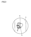
- an arcuate rib 15 is disposed on the outer surface of the cabinet 11 around the circular hole 11 a so as to surround the input terminal 14 like an arc from the rear part to the lower part as shown in Fig. 3 .
- an unstable movement of the antenna cable 105 when it is connected to or disconnected from the input terminal 14 can be restricted by the arcuate rib 15 in a wide range from the rear part to the lower part of the input terminal 14. Therefore, the input terminal 14 is not tilted more than a need with respect to the axial direction, so that a breakage of the television broadcasting receiver unit 12 can be prevented effectively.
- the arcuate rib 15 may be a semicircular rib that surrounds the input terminal 14 in a semicircular manner from the rear part via the lower part to the front part.
- the arcuate rib 15 can be reinforced by the linear ribs 16 so that the unstable movement of the antenna cable 105 can be restricted more securely.
Landscapes
- Engineering & Computer Science (AREA)
- Multimedia (AREA)
- Signal Processing (AREA)
- Devices For Indicating Variable Information By Combining Individual Elements (AREA)
- Structure Of Receivers (AREA)
- Support Of Aerials (AREA)
Abstract
Description
- The present invention relates to a liquid crystal television receiver. In particular, the present invention relates to a cabinet structure of a liquid crystal television receiver for preventing a breakage of a television broadcasting receiver unit.
-
JP-A-2004-134842 Fig. 4 is a vertical cross section showing a schematic structure of the conventional CRTtype television receiver 100, andFig. 5 is an enlarged perspective view of an important part of acabinet 101 of the conventional CRTtype television receiver 100 viewed from the rear side. - As shown in
Figs. 4 and 5 , thistelevision receiver 100 has a televisionbroadcasting receiver unit 102 that is mounted on acircuit board 103, and aninput terminal 104 passes through acircular hole 101 a provided to the rear side of thecabinet 101 at a lower part in the front and rear direction so as to protrude to the outside of thecabinet 101 so that an antenna cable (not shown) is connected to theinput terminal 104. - Here,
Fig. 6 shows an enlarged view of the televisionbroadcasting receiver unit 102. As shown inFig. 6 , the digitalbroadcasting receiver unit 102 has a box shape, and the above-mentionedinput terminal 104 is disposed on one side surface of the box so as to stand from the surface. - When the antenna cable is connected to the
input terminal 104 of the CRTtype television receiver 100, anantenna cable 105 will be held by a hand as shown inFig. 7 and inserted into theinput terminal 104 by moving theantenna cable 105 from the rear to the front of thecabinet 101 as shown by an arrow inFig. 7 . On this occasion, the hand may be unstable so that a stress may be exerted onto theinput terminal 104 not only in the axial direction (the direction of the arrow inFig. 4 ) but also in the direction perpendicular to the axial direction. Therefore, if only theinput terminal 104 is tilted substantially with respect to the axial direction while the televisionbroadcasting receiver unit 102 is fixed on thecircuit board 103, a large mechanical stress may be exerted onto the televisionbroadcasting receiver unit 102 by a lever mechanism with a fulcrum at thecircular hole 101 a of thecabinet 101. As a result, a breakage of the televisionbroadcasting receiver unit 102 may occur. - Therefore, a pair of
triangular ribs cabinet 101 around thecircular hole 101a at the positions sandwiching theinput terminal 104 side by side as shown inFig. 5 , so that thetriangular ribs antenna cable 105 in a substantially horizontal plane when it is connected to or disconnected from theinput terminal 104. Thus, theinput terminal 104 is not tilted more than a need with respect to the axial direction, so that a breakage of the televisionbroadcasting receiver unit 102 can be prevented. -
Fig. 8 is a perspective view viewed from the rear of a conventional liquidcrystal television receiver 200 in which the television broadcasting receiver unit is disposed, andFig. 9 is a horizontal cross section showing a schematic structure of the liquidcrystal television receiver 200. - As shown in
Figs. 8 and 9 , this liquidcrystal television receiver 200 has a televisionbroadcasting receiver unit 202 mounted on acircuit board 203 disposed inside acabinet 201. Aninput terminal 204 passes through acircular hole 201 a provided to the rear side of thecabinet 201 in the left and right direction so as to protrude to the outside of thecabinet 201 so that an antenna cable (not shown) is connected to theinput terminal 204. Note that the televisionbroadcasting receiver unit 202 has totally the same structure as the televisionbroadcasting receiver unit 102 shown inFig. 6 . The structure of such a liquid crystal television receiver is described in the above-mentioned patent document. - As to the above-mentioned liquid
crystal television receiver 200 too, theantenna cable 105 will be held by a hand as shown inFig. 10 and inserted into theinput terminal 204 by moving theantenna cable 105 from the left to the right of thecabinet 201 as shown by an arrow inFig. 10 when the antenna cable is connected to theinput terminal 204. On this occasion, the hand may be unstable so that a stress may be exerted onto theinput terminal 204 not only in the axial direction (the direction of the arrow inFig. 9 ) but also in the direction perpendicular to the axial direction.
Therefore, if only theinput terminal 204 is tilted substantially with respect to the axial direction while the televisionbroadcasting receiver unit 202 is fixed on thecircuit board 203, a large mechanical stress may be exerted onto the televisionbroadcasting receiver unit 202 by a lever mechanism with a fulcrum at thecircular hole 201 a of thecabinet 201. As a result, a breakage of the televisionbroadcasting receiver unit 202 may occur. - However, since the television broadcasting receiver unit of the liquid
crystal television receiver 200 is usually disposed on the upper part than the middle in the vertical direction of thecabinet 201, the unstable movement of theantenna cable 105 is apt to occur in the downward direction when it is connected or disconnected. Therefore, the countermeasure against the unstable movement in the substantially horizontal plane when theantenna cable 105 is connected to or disconnected from the above-mentioned CRT type television receiver 100 (i.e., providing a pair oftriangular ribs 106 and 107) is not sufficient. - It is an object of the present invention to restrict an unstable movement of an antenna cable when it is connected to or disconnected from an input terminal of a liquid crystal television receiver in a wide range, so that a breakage of a television broadcasting receiver unit is prevented.
- A liquid crystal television receiver according to a first aspect of the present invention includes a circular hole passing through a cabinet in a left and right direction, and an input terminal of a television broadcasting receiver unit mounted on a substrate disposed vertically in the cabinet, the television broadcasting receiver unit having the input terminal passing through the circular hole so as to protrude to the outside of the cabinet. An arcuate rib is disposed on the outer surface of the cabinet around the circular hole so as to surround the input terminal like an arc from the rear part to the lower part.
- As to a second aspect of the present invention, the liquid crystal television receiver of the first aspect further includes a plurality of linear ribs disposed on the outer surface of the arcuate rib so as to extend from the outer surface of the cabinet.
- According to the liquid crystal television receiver of the first aspect, since the arcuate rib is disposed on the outer surface of the cabinet around the circular hole so as to surround the input terminal like an arc from the rear part to the lower part, an unstable movement of the antenna cable when it is connected to or disconnected from the input terminal can be restricted by the arcuate rib in a wide range from the rear part to the lower part of the input terminal. Therefore, the input terminal is not tilted more than a need with respect to the axial direction, so that a breakage of the television broadcasting receiver unit can be prevented effectively.
- According to the liquid crystal television receiver of the second aspect, the arcuate rib is reinforced by the linear ribs so that the unstable movement of the antenna cable can be restricted more securely.
-
Fig. 1 is a perspective view of a liquid crystal television receiver viewed from the rear in which a television broadcasting receiver unit is disposed according to the present invention. -
Fig. 2 is a horizontal cross section showing a schematic structure of the liquid crystal television receiver shown inFig. 1 . -
Fig. 3 is an enlarged view of the encircled part shown inFig. 1 . -
Fig. 4 is a cross section showing a schematic structure of a conventional CRT type television receiver in which a television broadcasting receiver unit is disposed. -
Fig. 5 is an enlarged perspective view of an important part of a cabinet viewed from the rear of the CRT type television receiver shown inFig. 4 . -
Fig. 6 shows an enlarged view of the television broadcasting receiver unit. -
Fig. 7 is an explanatory diagram showing insertion of an antenna cable into an input terminal of the television broadcasting receiver unit of the CRT type television receiver shown inFig. 4 . -
Fig. 8 is a perspective view of the conventional liquid crystal television receiver viewed from the rear in which the television broadcasting receiver unit is disposed. -
Fig. 9 is a horizontal cross section showing a schematic structure of the liquid crystal television receiver shown inFig. 8 . -
Fig. 10 is an explanatory diagram showing insertion of an antenna cable into an input terminal of the television broadcasting receiver unit of the liquid crystal television receiver shown inFig. 8 . - Hereinafter, a best embodiment of the present invention will be described with reference to the attached drawings.
-
Fig. 1 is a perspective view of a liquidcrystal television receiver 10 viewed from the rear in which a television broadcasting receiver unit is disposed according to the present invention, andFig. 2 is a horizontal cross section showing a schematic structure of the liquidcrystal television receiver 10. - As shown in
Figs. 1 and 2 , this liquidcrystal television receiver 10 has a televisionbroadcasting receiver unit 12 mounted on acircuit board 13 disposed vertically in acabinet 11, and aninput terminal 14 passes through acircular hole 11 a provided to the rear side of thecabinet 11 in the left and right direction so as to protrude to the outside of thecabinet 11 so that an antenna cable (not shown) is connected to theinput terminal 14. Note that the televisionbroadcasting receiver unit 12 has totally the same structure as the televisionbroadcasting receiver unit 102 shown inFig. 6 . - As to the liquid
crystal television receiver 10 of the present invention, anarcuate rib 15 is disposed on the outer surface of thecabinet 11 around thecircular hole 11 a so as to surround theinput terminal 14 like an arc from the rear part to the lower part as shown inFig. 3 . Thus, an unstable movement of theantenna cable 105 when it is connected to or disconnected from theinput terminal 14 can be restricted by thearcuate rib 15 in a wide range from the rear part to the lower part of theinput terminal 14. Therefore, theinput terminal 14 is not tilted more than a need with respect to the axial direction, so that a breakage of the televisionbroadcasting receiver unit 12 can be prevented effectively. Note that thearcuate rib 15 may be a semicircular rib that surrounds theinput terminal 14 in a semicircular manner from the rear part via the lower part to the front part. - Furthermore, it is possible to provide a plurality of
linear ribs 16 extending on the outer face of thearcuate rib 15 from the outer face of thecabinet 11 as shown inFig. 3 . According to this structure, thearcuate rib 15 can be reinforced by thelinear ribs 16 so that the unstable movement of theantenna cable 105 can be restricted more securely.
Claims (2)
- A liquid crystal television receiver comprising:a circular hole passing through a cabinet in a left and right direction;an input terminal of a television broadcasting receiver unit mounted on a substrate disposed vertically in the cabinet, the television broadcasting receiver unit having the input terminal passing through the circular hole so as to protrude to the outside of the cabinet, whereinan arcuate rib is disposed on the outer surface of the cabinet around the circular hole so as to surround the input terminal like an arc from the rear part to the lower part.
- The liquid crystal television receiver according to claim 1, wherein a plurality of linear ribs are disposed on the outer surface of the arcuate rib so as to extend from the outer surface of the cabinet.
Applications Claiming Priority (1)
| Application Number | Priority Date | Filing Date | Title |
|---|---|---|---|
| JP2007141188A JP4301326B2 (en) | 2007-05-29 | 2007-05-29 | LCD television receiver |
Publications (3)
| Publication Number | Publication Date |
|---|---|
| EP1998563A2 true EP1998563A2 (en) | 2008-12-03 |
| EP1998563A3 EP1998563A3 (en) | 2011-08-03 |
| EP1998563B1 EP1998563B1 (en) | 2013-07-17 |
Family
ID=39627375
Family Applications (1)
| Application Number | Title | Priority Date | Filing Date |
|---|---|---|---|
| EP08155824.9A Not-in-force EP1998563B1 (en) | 2007-05-29 | 2008-05-07 | Liquid crystal television receiver |
Country Status (3)
| Country | Link |
|---|---|
| US (1) | US20080297663A1 (en) |
| EP (1) | EP1998563B1 (en) |
| JP (1) | JP4301326B2 (en) |
Families Citing this family (1)
| Publication number | Priority date | Publication date | Assignee | Title |
|---|---|---|---|---|
| CN107277498A (en) * | 2017-07-31 | 2017-10-20 | 东莞康佳电子有限公司 | A kind of processing unit of bore hole 3D vision signals |
Citations (1)
| Publication number | Priority date | Publication date | Assignee | Title |
|---|---|---|---|---|
| JP2004134842A (en) | 2002-10-08 | 2004-04-30 | Sharp Corp | Digital broadcast receiving unit |
Family Cites Families (7)
| Publication number | Priority date | Publication date | Assignee | Title |
|---|---|---|---|---|
| JP3520552B2 (en) * | 1994-03-29 | 2004-04-19 | ソニー株式会社 | Resin molded cabinet |
| JP3367343B2 (en) * | 1996-07-22 | 2003-01-14 | 松下電器産業株式会社 | Cabinet device of projection television receiver, molding die and resin molding method |
| JP3419442B2 (en) * | 1999-02-03 | 2003-06-23 | 船井電機株式会社 | Connector mounting structure |
| JP2005130398A (en) * | 2003-10-27 | 2005-05-19 | Toshiba Corp | Broadcast receiving apparatus |
| JP3711558B2 (en) * | 2003-11-18 | 2005-11-02 | 船井電機株式会社 | Television receiver cabinet |
| JP3106183U (en) * | 2004-06-25 | 2004-12-16 | 船井電機株式会社 | Liquid crystal television and liquid crystal display |
| KR100631978B1 (en) * | 2005-05-25 | 2006-10-09 | 삼성전기주식회사 | Thin TV tuner with improved chassis |
-
2007
- 2007-05-29 JP JP2007141188A patent/JP4301326B2/en not_active Expired - Fee Related
-
2008
- 2008-05-07 EP EP08155824.9A patent/EP1998563B1/en not_active Not-in-force
- 2008-05-28 US US12/153,955 patent/US20080297663A1/en not_active Abandoned
Patent Citations (1)
| Publication number | Priority date | Publication date | Assignee | Title |
|---|---|---|---|---|
| JP2004134842A (en) | 2002-10-08 | 2004-04-30 | Sharp Corp | Digital broadcast receiving unit |
Also Published As
| Publication number | Publication date |
|---|---|
| JP4301326B2 (en) | 2009-07-22 |
| EP1998563B1 (en) | 2013-07-17 |
| JP2008300893A (en) | 2008-12-11 |
| EP1998563A3 (en) | 2011-08-03 |
| US20080297663A1 (en) | 2008-12-04 |
Similar Documents
| Publication | Publication Date | Title |
|---|---|---|
| US7878855B2 (en) | Cable connector assembly with a front shell | |
| EP1803985B1 (en) | Panel-type television | |
| US8062054B2 (en) | Cable connector assembly with improved structure strength thereof | |
| US7658456B2 (en) | Television and rib structure | |
| JP4525723B2 (en) | Thin monitor device shield structure | |
| US20060087210A1 (en) | Plasma display apparatus | |
| EP1998563B1 (en) | Liquid crystal television receiver | |
| JP5502974B2 (en) | Television equipment, stands, and electronics | |
| JP5693015B2 (en) | Electronics | |
| JP2008186734A (en) | Case for jack | |
| EP1928173B1 (en) | Television and rib structure | |
| JP2014035946A (en) | On-board shield connector | |
| JP2001332367A (en) | CRT receiving socket provided with insulating ribs and monitor provided with the same | |
| JP2023140511A (en) | Electronics | |
| JP4020743B2 (en) | Digital broadcast receiving unit | |
| EP1727181A1 (en) | Plasma display apparatus | |
| JP5261957B2 (en) | Video display device | |
| JP5333535B2 (en) | Mounting structure of external connection terminal | |
| WO2012081401A1 (en) | Electronic device | |
| KR100611382B1 (en) | Panel mounting structure of display device | |
| JP2008103946A (en) | Display device | |
| JP7168349B2 (en) | Speaker mounting structure and television receiver having this structure | |
| US7629732B2 (en) | Cathode ray tube having a scatter-proof band | |
| JP2010212330A (en) | Tuner grounding structure | |
| KR100758658B1 (en) | Display device |
Legal Events
| Date | Code | Title | Description |
|---|---|---|---|
| PUAI | Public reference made under article 153(3) epc to a published international application that has entered the european phase |
Free format text: ORIGINAL CODE: 0009012 |
|
| AK | Designated contracting states |
Kind code of ref document: A2 Designated state(s): AT BE BG CH CY CZ DE DK EE ES FI FR GB GR HR HU IE IS IT LI LT LU LV MC MT NL NO PL PT RO SE SI SK TR |
|
| AX | Request for extension of the european patent |
Extension state: AL BA MK RS |
|
| PUAL | Search report despatched |
Free format text: ORIGINAL CODE: 0009013 |
|
| AK | Designated contracting states |
Kind code of ref document: A3 Designated state(s): AT BE BG CH CY CZ DE DK EE ES FI FR GB GR HR HU IE IS IT LI LT LU LV MC MT NL NO PL PT RO SE SI SK TR |
|
| AX | Request for extension of the european patent |
Extension state: AL BA MK RS |
|
| RIC1 | Information provided on ipc code assigned before grant |
Ipc: H04N 5/64 20060101AFI20110627BHEP |
|
| 17P | Request for examination filed |
Effective date: 20120203 |
|
| AKX | Designation fees paid |
Designated state(s): DE FR GB PL |
|
| GRAP | Despatch of communication of intention to grant a patent |
Free format text: ORIGINAL CODE: EPIDOSNIGR1 |
|
| RIN1 | Information on inventor provided before grant (corrected) |
Inventor name: SUGAMURA, TOMOKAZU |
|
| GRAS | Grant fee paid |
Free format text: ORIGINAL CODE: EPIDOSNIGR3 |
|
| GRAA | (expected) grant |
Free format text: ORIGINAL CODE: 0009210 |
|
| AK | Designated contracting states |
Kind code of ref document: B1 Designated state(s): DE FR GB PL |
|
| REG | Reference to a national code |
Ref country code: GB Ref legal event code: FG4D |
|
| REG | Reference to a national code |
Ref country code: DE Ref legal event code: R096 Ref document number: 602008026014 Country of ref document: DE Effective date: 20130912 |
|
| PG25 | Lapsed in a contracting state [announced via postgrant information from national office to epo] |
Ref country code: PL Free format text: LAPSE BECAUSE OF FAILURE TO SUBMIT A TRANSLATION OF THE DESCRIPTION OR TO PAY THE FEE WITHIN THE PRESCRIBED TIME-LIMIT Effective date: 20130717 |
|
| PLBE | No opposition filed within time limit |
Free format text: ORIGINAL CODE: 0009261 |
|
| STAA | Information on the status of an ep patent application or granted ep patent |
Free format text: STATUS: NO OPPOSITION FILED WITHIN TIME LIMIT |
|
| 26N | No opposition filed |
Effective date: 20140422 |
|
| REG | Reference to a national code |
Ref country code: DE Ref legal event code: R097 Ref document number: 602008026014 Country of ref document: DE Effective date: 20140422 |
|
| REG | Reference to a national code |
Ref country code: DE Ref legal event code: R119 Ref document number: 602008026014 Country of ref document: DE |
|
| GBPC | Gb: european patent ceased through non-payment of renewal fee |
Effective date: 20140507 |
|
| REG | Reference to a national code |
Ref country code: DE Ref legal event code: R119 Ref document number: 602008026014 Country of ref document: DE Effective date: 20141202 |
|
| REG | Reference to a national code |
Ref country code: FR Ref legal event code: ST Effective date: 20150130 |
|
| PG25 | Lapsed in a contracting state [announced via postgrant information from national office to epo] |
Ref country code: DE Free format text: LAPSE BECAUSE OF NON-PAYMENT OF DUE FEES Effective date: 20141202 |
|
| PG25 | Lapsed in a contracting state [announced via postgrant information from national office to epo] |
Ref country code: GB Free format text: LAPSE BECAUSE OF NON-PAYMENT OF DUE FEES Effective date: 20140507 Ref country code: FR Free format text: LAPSE BECAUSE OF NON-PAYMENT OF DUE FEES Effective date: 20140602 |