EP1998435A2 - Method and system for estimating rotor angular position and rotor angular velocity at low speeds or standstill - Google Patents
Method and system for estimating rotor angular position and rotor angular velocity at low speeds or standstill Download PDFInfo
- Publication number
- EP1998435A2 EP1998435A2 EP08251107A EP08251107A EP1998435A2 EP 1998435 A2 EP1998435 A2 EP 1998435A2 EP 08251107 A EP08251107 A EP 08251107A EP 08251107 A EP08251107 A EP 08251107A EP 1998435 A2 EP1998435 A2 EP 1998435A2
- Authority
- EP
- European Patent Office
- Prior art keywords
- produce
- signal
- transformed
- function
- output signal
- Prior art date
- Legal status (The legal status is an assumption and is not a legal conclusion. Google has not performed a legal analysis and makes no representation as to the accuracy of the status listed.)
- Granted
Links
Images


Classifications
-
- H—ELECTRICITY
- H02—GENERATION; CONVERSION OR DISTRIBUTION OF ELECTRIC POWER
- H02P—CONTROL OR REGULATION OF ELECTRIC MOTORS, ELECTRIC GENERATORS OR DYNAMO-ELECTRIC CONVERTERS; CONTROLLING TRANSFORMERS, REACTORS OR CHOKE COILS
- H02P21/00—Arrangements or methods for the control of electric machines by vector control, e.g. by control of field orientation
- H02P21/06—Rotor flux based control involving the use of rotor position or rotor speed sensors
-
- H—ELECTRICITY
- H02—GENERATION; CONVERSION OR DISTRIBUTION OF ELECTRIC POWER
- H02P—CONTROL OR REGULATION OF ELECTRIC MOTORS, ELECTRIC GENERATORS OR DYNAMO-ELECTRIC CONVERTERS; CONTROLLING TRANSFORMERS, REACTORS OR CHOKE COILS
- H02P21/00—Arrangements or methods for the control of electric machines by vector control, e.g. by control of field orientation
- H02P21/14—Estimation or adaptation of machine parameters, e.g. flux, current or voltage
- H02P21/18—Estimation of position or speed
Definitions
- This invention relates to rotor angular position and velocity sensing systems for mechanical shaft sensorless control of dynamoelectric machines, and more particularly to an improved system for resolving the position and velocity of a rotor for a dynamoelectric machine using an estimate of extended rotor flux.
- a motor may be utilized both as a motor and as a generator. Because of this dual function, the motor may be called a dynamoelectric machine.
- a typical motor comprises a stationary stator, and a rotating rotor. In some motors, it is necessary to detect a position of a rotor in order to sustain operation of the motor. Determining a rotor position typically requires a shaft position sensor. It is desirable to eliminate a mechanical shaft sensor to reduce cost and improve reliability.
- Some methods of sensorless rotor position detection include the back EMF method, which determines rotor position based on voltage, the signal injection method, which injects high frequencies into a system, and the method discussed in U.S. Patent No. 7,072,790 which uses flux to determine rotor position. It is desirable to improve the method U.S. Patent No. 7,072,790 for applications operating at low speeds or at a standstill.
- a method and system for estimating an angular position and an angular velocity of a rotor in a dynamoelectric machine measures an AC current and a potential for each of a plurality of windings coupled to a stator of the dynamoelectric machine, transforms the measured currents and potentials to a stationary frame to produce transformed currents and transformed potentials, and processes the transformed currents and transformed potentials to produce a first intermediate signal and a second intermediate signal.
- the first intermediate signal and the second intermediate signal are cross-coupled and processed to obtain a first extended rotor flux value and a second extended rotor flux value.
- the first extended rotor flux value and the second extended rotor flux value are applied to a phase lock loop to derive an estimated rotor angular position and an estimated rotor angular velocity for the dynamoelectric machine.
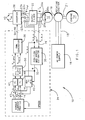
- the rotor angular position and velocity sensing system 10 comprises a motor 12 that is able to operate as a starter to start an engine 14, or as a generator to power a load (not shown). Because of this dual function, the motor 12 may be called a dynamoelectric machine. In one example, the motor 12 is a brushless motor that requires a controller to know a position of its rotor to operate.
- an AC power supply 16 provides an AC voltage along supply lines 18 to a rotating exciter 19.
- the AC power supply 16 provides three phases of AC power, however it is understood that other numbers of phases of AC power could be provided.
- the rotating exciter is connected to a shaft 21 that is also connected to the motor 12 and the engine 14.
- the AC voltage from the supply lines 18 induces an AC voltage along motor terminals 20a, 20b, and 20c.
- the induced voltage causes a current to flow through an output filter 22.
- a microprocessor 24 measures a voltage 26 and a current 28 from each of the terminals 20a, 20b, and 20c.
- a position and speed estimator 30 uses the voltage and current measurements to estimate a flux of the motor 12 and to estimate a rotor position 32 and a rotor angular velocity 34.
- an inverter 38 is turned ON.
- the microprocessor 24 processes the estimated rotor position 32 and estimated rotor angular velocity 34 to control a pulse width modulated (PWM) generator 36.
- Inverter 38 is coupled to the PWM generator 36 and converts a DC voltage from DC voltage supply lines 40 to AC. This voltage enables AC to flow through the output filter 22, which improves power quality by filtering out harmonics and reducing electromagnetic interference (EMI).
- EMI electromagnetic interference
- Figure 1 illustrates how the microprocessor 24 processes the estimated rotor position 32 and estimated rotor angular velocity 34 to control the inverter 38.
- An abc to d-q frame transformer 42 uses the estimated rotor position 32 to transform the current measurements 28 to a rotating d-q frame to obtain current values I d and Iq.
- a torque current profile generator 44 uses the estimated rotor angular velocity 34 to lookup reference current values I d * and I q *.
- Comparators 45 and 46 compare the transformed I d and Iq values to reference current values I d * and I q * to determine differences ⁇ I d and ⁇ I q between the transformed values and the reference values.
- Proportional and integral (PI) regulators 47 and 48 process the differences ⁇ I d and ⁇ I q using proportional and integral gains, and transmit an output signal to d-q to alpha-beta frame transformer 50, which converts the output into a stationary ⁇ - ⁇ frame to produce V alpha * and V beta * signals which are transmitted to the PWM generator 36.
- the PWM generator then controls the inverter 38 accordingly to produce a desired AC voltage.
- the output filter 22 comprises an inductor and a capacitor (not shown) in each phase.
- An input current I invt flows from the inverter 38 along the windings 23 a, 23b, and 23c to the output filter 22, and an output current I s flows from the output filter 22 along the terminals 20a, 20b, and 20c to the motor 12.
- the voltage measurements 26 and current measurements 28 are measured from each of the three terminals (20a, 20b, 20c) and each of the three windings (23a, 23b; 23c) in an a-b-c frame.
- the current measurement 28 is a measurement of the inverter output current I invt .
- the stationary ⁇ - ⁇ frame is a two phase frame and is a necessary step in calculating flux. Equation #3 is used to determine an ⁇ -axis voltage V ⁇ , a ⁇ -axis voltage V ⁇ , an ⁇ -axis current I ⁇ , and a ⁇ -axis current I ⁇ .
- ⁇ ext_ ⁇ ⁇ ext_ ⁇ 1 s ⁇ V ⁇ V ⁇ - R s 0 0 R s [ I ⁇ I ⁇ ] - [ L q 0 0 L q ] [ I ⁇ I ⁇ ]
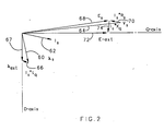
- Figure 2 illustrates a phasor diagram in the rotating d-q frame.
- Figure 2 illustrates the relationship between extended rotor flux and back EMF.
- a flux ⁇ s in the stator of the motor 12 is represented by a phasor 60.
- a stator current I s is represented by a phasor 62.
- a stator potential V s is represented by a phasor 64.
- a phasor 66 represents I s *L q where L q is a q-axis rotor inductance.
- a vector sum of the phasor 60, representing ⁇ s , and the phasor 66, representing I s *L q is an extended rotor flux ⁇ ext , which aligns with the d-axis of the d-q frame, and is represented by a phasor 67.
- a back electromotive force (EMF) E s is represented by a phasor 68. As shown in Figure 2 , the back EMF E s is perpendicular to the stator flux ⁇ s .
- the back EMF E s represented by the phasor 68, is a vector sum of the stator potential V s represented by phasor 64 and stator resistance potential drop I s *R s represented by a phasor 70, where R s is the stator resistance.
- An extended back electromotive force (EEMF), E ext , in the stator is represented by a phasor 72, and aligns with the q-axis of the d-q frame.
- I s *X q where X q is a q-axis stator reactance, is represented by a phasor 74.
- the extended back EMF represented by phasor 72 is a vector sum of E s represented by phasor 68 and I s *X q represented by a phasor 74.
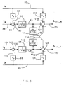
- Figure 3 illustrates a block diagram of the flux estimation algorithm shown in equation #5.
- a transformed measured current I ⁇ for the ⁇ -axis on a signal path 80 is multiplied by the stator resistance R s 82 to produce I ⁇ * R s on a signal path 84.
- a summer 86 subtracts I ⁇ * R s on the signal path 84 from the transformed potential V ⁇ on a signal path 88 to produce V ⁇ -( I ⁇ *R s ) on a signal path 90.
- V ⁇ - ( I ⁇ * R s ) on the signal path 90 is multiplied by a 1 s + ⁇ i first lag function 92 to produce first intermediate signal 1 s + ⁇ i ⁇ V ⁇ - I ⁇ * R s on a signal path 93.
- 1 s + ⁇ i ⁇ V ⁇ - I ⁇ * R s on the signal path 93 is multiplied by a ⁇ i s + ⁇ i second lag function 94 to produce ⁇ i s + ⁇ i ⁇ V ⁇ - I ⁇ * R s on a signal path 95.
- a transformed measured current I ⁇ for the ⁇ -axis on a signal path 96 is multiplied by the stator resistance R s 98 to produce I ⁇ * R s on a signal path 100.
- a summer 102 subtracts I ⁇ * R s on the signal path 100 from the transformed potential V ⁇ on a signal path 104 to produce V ⁇ - ( I ⁇ *R s ) on a signal path 106.
- V ⁇ -( I ⁇ *R s ) on the signal path 106 is multiplied by the 1 s + ⁇ i first lag function 108 to produce second intermediate signal 1 s + ⁇ i ⁇ V ⁇ - I ⁇ * R s on a signal path 110.
- the transformed measured current I ⁇ for the ⁇ -axis on the signal path 80 is also multiplied by a q-axis inductance L q 116 to produce I ⁇ *L q on the signal path 118.
- a summer 120 subtracts I ⁇ *L q on the signal path 118 from 1 s + ⁇ i ⁇ V ⁇ - I ⁇ * R s on the signal path 93 and adds ⁇ i s + ⁇ i ⁇ V ⁇ - I ⁇ * R s from the signal path 114 to produce 1 s + ⁇ i ( V ⁇ - I ⁇ * R s ) + ⁇ i s + ⁇ i 2 ( V ⁇ - I ⁇ * R s ) - I ⁇ * L q which corresponds to the extended rotor flux on the ⁇ -axis ⁇ ext_ ⁇ on the signal path 122.
- the " ⁇ "notation indicates that the extended rotor flux is an estimate based on measured
- the transformed measured current I ⁇ for the ⁇ -axis on the signal path 96 is also multiplied by a q-axis inductance L q 124 to produce I ⁇ *L q on the signal path 126.
- a summer 128 subtracts I ⁇ *L q on the signal path 126 from 1 s + ⁇ i ⁇ V ⁇ - I ⁇ * R s on the signal path 110 and subtracts ⁇ i s + ⁇ i ⁇ V ⁇ - I ⁇ * R s on the signal path 95 to produce 1 s + ⁇ i ⁇ V ⁇ - I ⁇ * R s - ⁇ i s + ⁇ i 2 ⁇ V ⁇ - I ⁇ * R s - I ⁇ * L q which corresponds to the extended rotor flux on the ⁇ -axis ⁇ est _ ⁇ on the signal path 130.
- the " ⁇ "notation indicates that the extended rotor flux is an estimate based on measured values
- the signal paths 95 and 114 cross-couple the signal paths 93 and 110.
- Equation #6 it would be possible to use an arctangent function to calculate a rotor position.
- Another option is to used a phase-locked loop (PLL) to derive position and angular velocity information.
- PLL phase-locked loop
- Figure 4 is a block diagram illustrating how the microprocessor 24 uses a phase lock loop (PLL) to improve an estimate of rotor angular position and rotor angular velocity.
- the estimated ⁇ -axis extended rotor flux ⁇ ext _ ⁇ and the estimated ⁇ -axis extended rotor flux ⁇ ext _ ⁇ are applied to the signal paths 122 and 130.
- a multiplier 132 multiplies the estimated ⁇ -axis extended rotor flux ⁇ ext_ ⁇ with a feedback signal on a signal path 134 from a sine function 136 to produce an ⁇ -axis multiplier output signal on a signal path 138.
- a multiplier 140 multiplies the estimated ⁇ -axis extended rotor flux ⁇ ext_ ⁇ with a feedback signal on a signal path 142 from a cosine function 144 to produce a ⁇ -axis multiplier output signal on a signal path 146.
- a summer 148 subtracts the ⁇ -axis multiplier output signal on the signal path 138 from the ⁇ -axis multiplier output signal on the signal path 146 to produce a difference signal on a signal path 150.
- a proportional and integral (PI) regulator function 152 multiplies the difference signal on the signal path 150 by the function K p + K i s to produce a PI output signal on a signal path 154.
- K i is an integral gain of the PI function 152
- K p is a proportional gain of the PI function 152. Both K i and K p are constants based on a design of the system 10 as shown in Figure 1 .
- An integral function 156 multiplies the PI output signal on the signal path 154 by the function 1 s to produce an integration output signal on a signal path 158.
- the integration output signal on the signal path 158 is also fed into the inputs of the sine function 136 and the cosine function 144 to provide the PLL.
- a low pass filter (LPF) function 160 multiplies the PI output signal on the signal path 154 by a third lag function ⁇ c s + ⁇ c to produce an estimated rotor angular velocity ⁇ on a signal line 162, where ⁇ c is a corner or cutoff frequency of the LPF function 160.
- a low pass filter associated with the LPF function 160 is used to smooth out the signal on the signal line 154.
- the integration output signal on the signal path 158 is compensated by an offset ⁇ ⁇ to obtain a final estimated rotor angular position ⁇ .
- the offset ⁇ ⁇ can be a lump-sum error of miscellaneous delays, including delays introduced by the lag functions 92, 108 of Figure 3 , digital sampling delays introduced in measured voltage and current signals, and computation delays in the microprocessor 24 as shown in Figure 1 .
- a lookup table 164 may be used to compensate for this phase delay ⁇ ⁇ .
- the lookup table 164 generates a suitable phase delay ⁇ ⁇ on a signal path 166, and a summer 168 subtracts the phase delay ⁇ ⁇ from the integration output signal on the signal path 158 to produce the estimated rotor angular position ⁇ on a signal path 170.
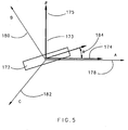
- Figure 5 illustrates how the ⁇ - ⁇ frame 173 comprises an ⁇ -axis 174 and a ⁇ -axis 175 that are perpendicular to each other.
- the ⁇ - ⁇ frame 173 aligns with a first phase 178, a second phase 180 and a third phase 182 of the system 10.
- a rotor 172 rotates, and its displacement from the ⁇ -axis is shown by the angle ⁇ 184, which is the rotor angular position to be estimated.
- the measured voltage 26 can be transformed to an alpha-beta frame.
- the transformed measured voltages V ⁇ and V ⁇ may be fed into the PLL as shown in Figure 4 to obtain the initial position angle ⁇ 0 .
- the voltage V ⁇ replaces the flux ⁇ ext_ ⁇ on the signal path 122
- the voltage V ⁇ replaces the flux ⁇ est_ ⁇ on the signal path 130 in Figure 4 .
- Figure 6 illustrates an initial stator voltage and an initial rotor position as a function of time.
- the rotating exciter 19 is powered on by the ac power supply 16 in Figure 1 .
- Graph 186 illustrates a line-to-line voltage for each phase of the motor 12 as a function of time
- graph 188 illustrates an estimated rotor position as a function of time in the motor 12.
- the inverter 38 is OFF in the time periods shown in graphs 186 and 188.
- a voltage 190 corresponds to a V BC line-to-line voltage
- a voltage 192 corresponds to a V CA line-to-line voltage
- a voltage 194 corresponds to a V AB line-to-line voltage.
- An estimated rotor position ⁇ 0 200 corresponds to an angle of the rotor 172.
- the AC power supply 16 is OFF, and the three voltages 190, 192, and 194 are close to zero and the estimated rotor position ⁇ 0 200 cannot be used to determine actual rotor position. Specifically, if each of the voltages does not exceed a certain threshold, the extended rotor flux values are not applied to the phase lock loop to derive an estimated rotor angular position and an estimated rotor angular velocity, and the estimated rotor angular position and estimated rotor angular velocity are designated as invalid.
- the AC power supply 16 turns ON and current flows to the rotating exciter 19 through the supply line 18 in the system 10. During this period, an excitation magnetic field of the motor 12 is arising.
- the rising magnetic flux induces voltage at the terminals 20a, 20b, and 20c of the system 10.
- the magnitude of voltages 190, 192 and 194 is sufficient for the microprocessor 24 to be able to estimate rotor position ⁇ 0 200.
- graph 188 From time 198 to approximately time 202 the value of ⁇ 0 remains stable, and after time 202 the value starts to fluctuate due to a decaying voltage signal as shown in graph 186.
- This stable period demonstrates that a rotor position can be estimated from the voltages 190, 192, and 194 during the stable time period. If the rotor angular position cannot be determined within a predetermined period of time after the rotating exciter is turned on, the system indicates a fault condition. If the rotor angular position can be determined within a predetermined period of time after the rotating exciter is turned on, the inverter is turned on.
Landscapes
- Engineering & Computer Science (AREA)
- Power Engineering (AREA)
- Control Of Motors That Do Not Use Commutators (AREA)
- Control Of Ac Motors In General (AREA)
- Synchronous Machinery (AREA)
Abstract
Description
- This invention relates to rotor angular position and velocity sensing systems for mechanical shaft sensorless control of dynamoelectric machines, and more particularly to an improved system for resolving the position and velocity of a rotor for a dynamoelectric machine using an estimate of extended rotor flux.
- In some vehicles, including some aircraft, a motor may be utilized both as a motor and as a generator. Because of this dual function, the motor may be called a dynamoelectric machine. A typical motor comprises a stationary stator, and a rotating rotor. In some motors, it is necessary to detect a position of a rotor in order to sustain operation of the motor. Determining a rotor position typically requires a shaft position sensor. It is desirable to eliminate a mechanical shaft sensor to reduce cost and improve reliability.
- Some methods of sensorless rotor position detection include the back EMF method, which determines rotor position based on voltage, the signal injection method, which injects high frequencies into a system, and the method discussed in
U.S. Patent No. 7,072,790 which uses flux to determine rotor position. It is desirable to improve the methodU.S. Patent No. 7,072,790 for applications operating at low speeds or at a standstill. - A method and system for estimating an angular position and an angular velocity of a rotor in a dynamoelectric machine measures an AC current and a potential for each of a plurality of windings coupled to a stator of the dynamoelectric machine, transforms the measured currents and potentials to a stationary frame to produce transformed currents and transformed potentials, and processes the transformed currents and transformed potentials to produce a first intermediate signal and a second intermediate signal. The first intermediate signal and the second intermediate signal are cross-coupled and processed to obtain a first extended rotor flux value and a second extended rotor flux value. The first extended rotor flux value and the second extended rotor flux value are applied to a phase lock loop to derive an estimated rotor angular position and an estimated rotor angular velocity for the dynamoelectric machine.
- These and other features of the present invention can be best understood from the following specification and drawings, the following of which is a brief description, and which describe certain embodiments of the invention by way of example only.
-
-
Figure 1 illustrates a block diagram of a mechanical sensorless rotor angular position and velocity sensing system. -
Figure 2 illustrates a phasor diagram of electrical parameters related to extended rotor flux. -
Figure 3 illustrates a block diagram of operations performed within the system ofFigure 1 to calculate a first extended rotor flux value and a second extended rotor flux value. -
Figure 4 illustrates a block diagram of how a microprocessor ofFigure 1 uses a phase lock loop (PLL) to obtain an estimated rotor angular position and an estimated rotor angular velocity. -
Figure 5 illustrates how a stationary frame of the system ofFigure 1 aligns with multiple phases of AC. -
Figure 6 illustrates an initial stator voltage and an initial rotor position as a function of time. - As shown in
Figure 1 , the rotor angular position andvelocity sensing system 10 comprises amotor 12 that is able to operate as a starter to start anengine 14, or as a generator to power a load (not shown). Because of this dual function, themotor 12 may be called a dynamoelectric machine. In one example, themotor 12 is a brushless motor that requires a controller to know a position of its rotor to operate. - To start the
motor 12, anAC power supply 16 provides an AC voltage along supply lines 18 to a rotatingexciter 19. In the example ofFigure 1 , theAC power supply 16 provides three phases of AC power, however it is understood that other numbers of phases of AC power could be provided. The rotating exciter is connected to ashaft 21 that is also connected to themotor 12 and theengine 14. - The AC voltage from the supply lines 18 induces an AC voltage along
motor terminals output filter 22. Amicroprocessor 24 measures avoltage 26 and a current 28 from each of theterminals speed estimator 30 uses the voltage and current measurements to estimate a flux of themotor 12 and to estimate arotor position 32 and a rotor angular velocity 34. - Once the estimated
rotor position 32 and estimated rotor angular velocity 34 have been calculated, aninverter 38 is turned ON. Themicroprocessor 24 processes the estimatedrotor position 32 and estimated rotor angular velocity 34 to control a pulse width modulated (PWM)generator 36.Inverter 38 is coupled to thePWM generator 36 and converts a DC voltage from DCvoltage supply lines 40 to AC. This voltage enables AC to flow through theoutput filter 22, which improves power quality by filtering out harmonics and reducing electromagnetic interference (EMI). The AC from theterminals motor 12 to sustain operation of themotor 12. -
Figure 1 illustrates how themicroprocessor 24 processes the estimatedrotor position 32 and estimated rotor angular velocity 34 to control theinverter 38. An abc tod-q frame transformer 42 uses the estimatedrotor position 32 to transform thecurrent measurements 28 to a rotating d-q frame to obtain current values Id and Iq. A torquecurrent profile generator 44 uses the estimated rotor angular velocity 34 to lookup reference current values Id* and Iq*.Comparators - Proportional and integral (PI)
regulators beta frame transformer 50, which converts the output into a stationary α-β frame to produce Valpha* and Vbeta* signals which are transmitted to thePWM generator 36. The PWM generator then controls theinverter 38 accordingly to produce a desired AC voltage. - The
output filter 22 comprises an inductor and a capacitor (not shown) in each phase. An input current Iinvt flows from theinverter 38 along thewindings output filter 22, and an output current Is flows from theoutput filter 22 along theterminals motor 12. The current flowing through the capacitor can be calculated by the following equation:
- where Îc is an estimated capacitor current; and
- Vs is one of the
voltage measurements 26. - where Is is the calculated motor current; and
- Iinvt is the inverter output current.
- The
voltage measurements 26 andcurrent measurements 28 are measured from each of the three terminals (20a, 20b, 20c) and each of the three windings (23a, 23b; 23c) in an a-b-c frame. Thecurrent measurement 28 is a measurement of the inverter output current Iinvt. A flux estimation is implemented in an alpha-beta (α-β) stationary frame. The relationship between the α-β frame and the a-b-c frame is described in the following equation:
- where f can be replaced with voltage, current, or flux;
- α, b, and c represent the phases of current on the
terminals - α and β represent axes of the α-β frame.
- The stationary α-β frame is a two phase frame and is a necessary step in calculating flux.
Equation # 3 is used to determine an α-axis voltage Vα, a β-axis voltage Vβ, an α-axis current Iα, and a β-axis current Iβ. - The following equation can then be used to determine an extended rotor flux in the α-β stationary frame:

- where λ ext_α is an alpha extended rotor flux;
- λ ext_β is a beta extended rotor flux;
- Rs is a stator resistance;
- Lq is a q-axis inductance; and
- 1/s is an integrator.
- where ωi is a selected corner frequency.
-
Figure 2 illustrates a phasor diagram in the rotating d-q frame.Figure 2 illustrates the relationship between extended rotor flux and back EMF. - A flux λs in the stator of the
motor 12 is represented by aphasor 60. A stator current Is is represented by aphasor 62. A stator potential Vs is represented by aphasor 64. Aphasor 66 represents Is*Lq where Lq is a q-axis rotor inductance. A vector sum of thephasor 60, representing λs, and thephasor 66, representing Is*Lq, is an extended rotor flux λext, which aligns with the d-axis of the d-q frame, and is represented by aphasor 67. - A back electromotive force (EMF) Es is represented by a
phasor 68. As shown inFigure 2 , the back EMF Es is perpendicular to the stator flux λs . The back EMF Es , represented by thephasor 68, is a vector sum of the stator potential Vs represented byphasor 64 and stator resistance potential drop Is*Rs represented by aphasor 70, where Rs is the stator resistance. - An extended back electromotive force (EEMF), Eext , in the stator is represented by a
phasor 72, and aligns with the q-axis of the d-q frame. Is*Xq , where Xq is a q-axis stator reactance, is represented by aphasor 74. The extended back EMF represented byphasor 72 is a vector sum of Es represented byphasor 68 and Is*Xq represented by aphasor 74. -
Figure 3 illustrates a block diagram of the flux estimation algorithm shown inequation # 5. As shown inFigure 3 , a transformed measured current Iα for the α-axis on asignal path 80 is multiplied by thestator resistance R s 82 to produce Iα *Rs on asignal path 84. Asummer 86 subtracts Iα * Rs on thesignal path 84 from the transformed potential V α on asignal path 88 to produce V α-(Iα*Rs ) on asignal path 90. Vα- (Iα *Rs ) on thesignal path 90 is multiplied by a
first lag function 92 to produce first intermediate signal
signal path 93.
signal path 93 is multiplied by a
second lag function 94 to produce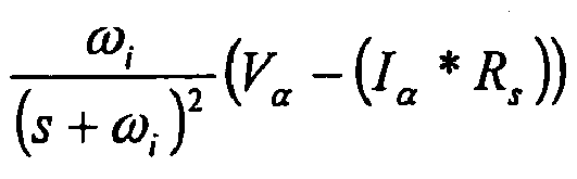
signal path 95. - Additionally, a transformed measured current I β for the β-axis on a
signal path 96 is multiplied by thestator resistance R s 98 to produce Iβ *Rs on asignal path 100. Asummer 102 subtracts Iβ *Rs on thesignal path 100 from the transformed potential Vβ on asignal path 104 to produce Vβ-(Iβ*Rs ) on asignal path 106. Vβ -(Iβ*Rs ) on thesignal path 106 is multiplied by the
first lag function 108 to produce second intermediate signal
signal path 110.
signal path 110 is multiplied by the
second lag function 112 to produce
signal path 114. - The transformed measured current I α for the α-axis on the
signal path 80 is also multiplied by a q-axis inductance L q 116 to produce I α *Lq on thesignal path 118. Asummer 120 subtracts Iα*Lq on thesignal path 118 from
signal path 93 and adds
signal path 114 to produce
λ ext_α on thesignal path 122. The "^"notation indicates that the extended rotor flux is an estimate based on measured values. - Additionally, the transformed measured current Iβ for the β-axis on the
signal path 96 is also multiplied by a q-axis inductance L q 124 to produce Iβ*Lq on the signal path 126. Asummer 128 subtracts Iβ*Lq on the signal path 126 from
signal path 110 and subtracts
signal path 95 to produce
λ est_β on thesignal path 130. Once again, the "^"notation indicates that the extended rotor flux is an estimate based on measured values. - As shown in
Figure 3 , thesignal paths signal paths - The following equation can be used to describe the relationship between the extended rotor flux and the rotor position:

- where θ is the rotor position; and
- λ is a flux amplitude.
- Using equation #6, it would be possible to use an arctangent function to calculate a rotor position. Another option is to used a phase-locked loop (PLL) to derive position and angular velocity information.
-
Figure 4 is a block diagram illustrating how themicroprocessor 24 uses a phase lock loop (PLL) to improve an estimate of rotor angular position and rotor angular velocity. The estimated α-axis extended rotor fluxλ ext_α and the estimated β-axis extended rotor fluxλ ext_β are applied to thesignal paths multiplier 132 multiplies the estimated α-axis extended rotor fluxλ ext_α with a feedback signal on asignal path 134 from asine function 136 to produce an α-axis multiplier output signal on asignal path 138. Likewise, amultiplier 140 multiplies the estimated β-axis extended rotor fluxλ ext_β with a feedback signal on asignal path 142 from acosine function 144 to produce a β-axis multiplier output signal on asignal path 146. - A
summer 148 subtracts the α-axis multiplier output signal on thesignal path 138 from the β-axis multiplier output signal on thesignal path 146 to produce a difference signal on asignal path 150. A proportional and integral (PI)regulator function 152 multiplies the difference signal on thesignal path 150 by the function
signal path 154. Ki is an integral gain of thePI function 152, and Kp is a proportional gain of thePI function 152. Both Ki and Kp are constants based on a design of thesystem 10 as shown inFigure 1 . - An
integral function 156 multiplies the PI output signal on thesignal path 154 by the function
signal path 158. The integration output signal on thesignal path 158 is also fed into the inputs of thesine function 136 and thecosine function 144 to provide the PLL. - A low pass filter (LPF)
function 160 multiplies the PI output signal on thesignal path 154 by a third lag function
signal line 162, where ωc is a corner or cutoff frequency of theLPF function 160. A low pass filter associated with theLPF function 160 is used to smooth out the signal on thesignal line 154. - The integration output signal on the
signal path 158 is compensated by an offset Δθ to obtain a final estimated rotor angular positionθ̂ . The offset Δθ can be a lump-sum error of miscellaneous delays, including delays introduced by the lag functions 92, 108 ofFigure 3 , digital sampling delays introduced in measured voltage and current signals, and computation delays in themicroprocessor 24 as shown inFigure 1 . A lookup table 164 may be used to compensate for this phase delay Δθ. The lookup table 164 generates a suitable phase delay Δθ on asignal path 166, and asummer 168 subtracts the phase delay Δθ from the integration output signal on thesignal path 158 to produce the estimated rotor angular positionθ̂ on asignal path 170. -
Figure 5 illustrates how the α-β frame 173 comprises an α-axis 174 and a β-axis 175 that are perpendicular to each other. The α-β frame 173 aligns with afirst phase 178, asecond phase 180 and athird phase 182 of thesystem 10. Arotor 172 rotates, and its displacement from the α-axis is shown by theangle θ 184, which is the rotor angular position to be estimated. - When the
motor 12 is at a standstill, as magnetic flux in themotor 12 changes in magnitude, a voltage is induced on themotor terminals microprocessor 24. The induced stator voltages in the α-β frame can be described by the following equation:

- where λs is a magnitude of stator flux; and
- θ0 is an initial rotor position angle at standstill.
- The measured
voltage 26 can be transformed to an alpha-beta frame. The transformed measured voltages Vα and Vβ may be fed into the PLL as shown inFigure 4 to obtain the initial position angle θ0 . In that case, the voltage V α replaces the fluxλ̂ ext_α on thesignal path 122, and the voltage V β replaces the fluxλ̂ est_β on thesignal path 130 inFigure 4 . -
Figure 6 illustrates an initial stator voltage and an initial rotor position as a function of time. During startup the rotatingexciter 19 is powered on by theac power supply 16 inFigure 1 .Graph 186 illustrates a line-to-line voltage for each phase of themotor 12 as a function of time, andgraph 188 illustrates an estimated rotor position as a function of time in themotor 12. Theinverter 38 is OFF in the time periods shown ingraphs voltage 190 corresponds to a VBC line-to-line voltage, avoltage 192 corresponds to a VCA line-to-line voltage, and avoltage 194 corresponds to a VAB line-to-line voltage. An estimated rotor position θ0 200 corresponds to an angle of therotor 172. - During an
initial time period 196, theAC power supply 16 is OFF, and the threevoltages time 198, theAC power supply 16 turns ON and current flows to the rotatingexciter 19 through the supply line 18 in thesystem 10. During this period, an excitation magnetic field of themotor 12 is arising. The rising magnetic flux induces voltage at theterminals system 10. The magnitude ofvoltages microprocessor 24 to be able to estimaterotor position θ 0 200. Ingraph 188, fromtime 198 to approximatelytime 202 the value of θ0 remains stable, and aftertime 202 the value starts to fluctuate due to a decaying voltage signal as shown ingraph 186. This stable period demonstrates that a rotor position can be estimated from thevoltages - Although a preferred embodiment of this invention has been disclosed, a worker of ordinary skill in this art would recognize that certain modifications would come within the scope of this invention. For that reason, the following claims should be studied to determine the true scope and content of this invention.


Claims (17)
- A method of estimating rotor angular position and rotor angular velocity for a dynamoelectric machine (12) comprising the steps of:measuring an AC current (28) and a potential (26) for each of a plurality of windings coupled to a stator of the dynamoelectric machine;transforming the plurality AC currents and potentials to a stationary frame (α-β) to produce a first transformed current, a second transformed current, a first transformed potential, and a second transformed potential;processing the first transformed current and the first transformed potential, and processing the second transformed current and the second transformed potential to obtain a first intermediate signal (93) and a second intermediate signal (110);cross-coupling and processing the first intermediate signal and the second intermediate signal to obtain a first extended rotor flux value (122) and a second extended rotor flux value (130); andapplying the first extended rotor flux value and the second extended rotor flux value to a phase lock loop (132-158) to derive an estimated rotor angular position and an estimated rotor angular velocity for the dynamoelectric machine.
- The method of claim 1, wherein the stationary frame is a two-phase α-β frame having an α-axis and a β-axis, and the first transformed current is Iα , the second transformed current is Iβ, the first transformed potential is Vα , the second transformed potential is Vβ , the first extended rotor flux value corresponds to the α-axis, and the second extended rotor flux value corresponds to the β-axis.
- The method of claim 2, wherein the step of processing the first transformed current and the first transformed potential, and processing the second transformed current and the second transformed potential to obtain a first intermediate signal and a second intermediate signal comprises the steps of:multiplying the first transformed current Iα and the second transformed current Iβ by a resistance Rs of the stator to produce signals Iα*RsIβ*Rs ;subtracting the signals Iα*Rs,Iβ*Rs from the first transformed potential Vα and the second transformed potential Vβ to produce signals Vα-Iα*Rs,Vβ-Iβ*Rs; andmultiplying the signals Vα-Iα*Rs,V β -Iβ*Rs by a first lag function


- The method of claim 3, wherein the step of cross-coupling and processing the first intermediate signal and the second intermediate signal comprises the steps of:multiplying the first intermediate signal


 multiplying the transformed currents Iα,Iβ by a q-axis inductance Lq of the stator to produce signals Iα*Lq,Iβ*Lq;adding the signal
 subtracting the signal

- The method of claim 3 or 4, wherein the selected corner frequency ωi is fixed.
- The method of claim 3 or 4, wherein the selected corner frequency ω i is adjustable.
- The method of any preceding claim, wherein the step of applying the first extended rotor flux value and the second extended rotor flux value to a phase lock loop to derive an estimated rotor angular position and an estimated rotor angular velocity for the dynamoelectric machine comprises the steps of:multiplying the first extended rotor flux value with a sine function feedback signal to produce an α-axis multiplier output signal;multiplying the second extended rotor flux value with a cosine function feedback signal to produce an β-axis multiplier output signal;subtracting the α-axis multiplier output signal from the β-axis multiplier output signal to produce a difference signal;multiplying the difference signal by a proportional and integral regulator function
 multiplying the PI output signal by an integral function
 multiplying the integration output signal by a sine function to produce the sine feedback signal; andmultiplying the integration output signal by a cosine function to produce the cosine feedback signal, wherein the estimated rotor angular position and the estimated rotor angular velocity for the dynamoelectric machine are derived from the proportional and integral regulator function output signal and the integration output signal.
 - The method of claim 7, further comprising the steps of:multiplying the proportional and integral regulator function output signal by a low pass filter function
 generating a delay compensation based on a value of the estimated rotor angular velocity; andsubtracting the delay compensation from the integration output signal to produce the estimated rotor angular position.
 - The method as recited in any preceding claim, further comprising the step of monitoring the potentials of the plurality of windings coupled to the stator of the dynamoelectric machine, wherein if the potentials do not exceed a certain threshold, the step of applying the first extended rotor flux value and the second extended rotor flux value to a phase lock loop to derive an estimated rotor angular position and an estimated rotor angular velocity for the dynamoelectric machine is not performed.
- The method of any preceding claim, further comprising the step of indicating a fault condition if the rotor angular position for the dynamoelectric machine cannot be determined within a predetermined period of time.
- A control for estimating an initial rotor angular position and a rotor angular velocity for a dynamoelectric machine (12) from a standstill comprising:a reference frame transformation function for transforming an AC potential (26) for each of a plurality of windings coupled to a stator of the dynamoelectric machine to a stationary frame (α-β) to produce a first transformed potential and a second transformed potential; anda phase lock loop (132-158) to derive an estimated rotor angular position and an estimated rotor angular velocity for the dynamoelectric machine from the first transformed potential and the second transformed potential.
- The control of claim 11, wherein if the potential of each of the plurality of windings does not exceed a certain threshold, the control designates the estimated rotor angular position and estimated rotor angular velocity as invalid.
- The control of claim 11 or 12, wherein if the rotor angular position for the dynamoelectric machine cannot be determined within a predetermined period of time after a rotating exciter (19) is powered on, the system indicates a fault condition.
- The control of claim 11, 12 or 13, wherein if the rotor angular position for the dynamoelectric machine can be determined within a predetermined period of time after a rotating exciter (19) is powered on, an inverter is turned on.
- The control of claim 11, 12, 13 or 14 wherein the stationary frame is a two-phase α-β frame having an α-axis and a β-axis, and the first transformed potential is Vα and the second transformed potential is Vβ .
- The control of any of claims 11 to 15, wherein the phase lock loop to derive an estimated rotor angular position value and an estimated rotor velocity value for the dynamoelectric machine from the first transformed potential and the second transformed potential comprises:a first multiplier (132) for multiplying the first transformed potential with a sine function feedback signal to produce an α-axis multiplier output signal;a second multiplier (140) for multiplying the second transformed potential with a cosine function feedback signal to produce an β-axis multiplier output signal;a first summer (148) for subtracting the α-axis multiplier output signal from the β-axis multiplier output signal to produce a difference signal;a proportional and integral regulator function (152) for multiplying the difference signal by a function
 an integral function (156) for multiplying the PI output signal by an integral function
 a sine function (136) for multiplying the integration output signal by a sine function to produce the sine feedback signal; anda cosine function (144) for multiplying the integration output signal by a cosine function to produce the cosine feedback signal, wherein the estimated rotor angular position and the estimated rotor angular velocity for the dynamoelectric machine are derived from the proportional and integral regulator function output signal and the integration output signal.
 - The control of claim 16, further comprising:a low pass filter (160) for filtering the PI output signal by a low pass filter function
 a lookup table (164) for generating a delay compensation based on a value of the estimated rotor angular velocity; anda second summer (168) for subtracting the delay compensation from the integration output signal to produce the estimated rotor angular position.
Applications Claiming Priority (1)
| Application Number | Priority Date | Filing Date | Title |
|---|---|---|---|
| US11/754,396 US7577545B2 (en) | 2007-05-29 | 2007-05-29 | Method and system for estimating rotor angular position and rotor angular velocity at low speeds or standstill |
Publications (3)
| Publication Number | Publication Date |
|---|---|
| EP1998435A2 true EP1998435A2 (en) | 2008-12-03 |
| EP1998435A3 EP1998435A3 (en) | 2011-12-07 |
| EP1998435B1 EP1998435B1 (en) | 2013-07-24 |
Family
ID=39639595
Family Applications (1)
| Application Number | Title | Priority Date | Filing Date |
|---|---|---|---|
| EP08251107.2A Active EP1998435B1 (en) | 2007-05-29 | 2008-03-27 | Method and system for estimating rotor angular position and rotor angular velocity at low speeds or standstill |
Country Status (2)
| Country | Link |
|---|---|
| US (1) | US7577545B2 (en) |
| EP (1) | EP1998435B1 (en) |
Cited By (6)
| Publication number | Priority date | Publication date | Assignee | Title |
|---|---|---|---|---|
| CN102651630A (en) * | 2012-04-25 | 2012-08-29 | 浙江天煌科技实业有限公司 | Measurement method for stator flux linkage of doubly-fed alternating-current excitation generator |
| CN105322846A (en) * | 2015-12-23 | 2016-02-10 | 北京机械设备研究所 | Permanent-magnetic synchronizing motor rotor magnetic-pole position detection device based on phase-locked loop |
| CN105515486A (en) * | 2015-12-03 | 2016-04-20 | 北京机械设备研究所 | Real-time compensation and correction method for rotor magnetic pole position of permanent magnet synchronous motor |
| CN106655919A (en) * | 2016-12-26 | 2017-05-10 | 北京机械设备研究所 | Brushless DC motor commutation circuit based on position sensorless |
| ITUB20155550A1 (en) * | 2015-11-13 | 2017-05-13 | Piaggio & C Spa | METHOD OF CONTROL OF A UNIT OF PROPULSION FOR BICYCLE WITH ASSISTED RIDER PEDAL AND ITS ASSISTED BIKE |
| US9705438B2 (en) | 2015-07-14 | 2017-07-11 | Infineon Technologies Austria Ag | Controller for a free-running motor |
Families Citing this family (30)
| Publication number | Priority date | Publication date | Assignee | Title |
|---|---|---|---|---|
| EP2023479B1 (en) * | 2007-08-06 | 2014-04-16 | Baumüller Nürnberg Gmbh | System for seamless velocity and/or location determination including standstill for a permanent magnet rotor of an electric machine |
| DK176958B1 (en) * | 2007-12-19 | 2010-07-26 | Vestas Wind Sys As | Generator system with intelligent processing of position signal |
| WO2009088908A1 (en) * | 2008-01-04 | 2009-07-16 | Delphi Technologies, Inc. | Methods and systems involving determining shaft velocity |
| JP5256009B2 (en) * | 2008-12-12 | 2013-08-07 | 日立アプライアンス株式会社 | Magnet motor speed control device |
| US7804184B2 (en) * | 2009-01-23 | 2010-09-28 | General Electric Company | System and method for control of a grid connected power generating system |
| US8354817B2 (en) * | 2009-06-18 | 2013-01-15 | GM Global Technology Operations LLC | Methods and systems for diagnosing stator windings in an electric motor |
| DE102009027346A1 (en) * | 2009-06-30 | 2011-01-05 | Robert Bosch Gmbh | Method and electrical circuit for operating an electric motor, in particular a servomotor for a component of an internal combustion engine |
| US8253365B2 (en) * | 2009-10-20 | 2012-08-28 | GM Global Technology Operations LLC | Methods and systems for performing fault diagnostics for rotors of electric motors |
| US8497698B2 (en) | 2010-08-11 | 2013-07-30 | GM Global Technology Operations LLC | Methods and systems for diagnosing faults for rotors of electric motors |
| KR101382305B1 (en) * | 2010-12-06 | 2014-05-07 | 현대자동차주식회사 | Motor control device for hybrid vehicle |
| US8593095B2 (en) | 2011-05-24 | 2013-11-26 | Hamilton Sundstrand Corporation | Wound field synchronous machine rotor tracking using a carrier injection sensorless signal and exciter current |
| KR20130057902A (en) * | 2011-11-24 | 2013-06-03 | 엘에스산전 주식회사 | A method for controlling an elevator, a control apparatus of elevator using it and an elevator using it |
| US8649887B2 (en) | 2012-05-22 | 2014-02-11 | GM Global Technology Operations LLC | Methods, systems and apparatus for implementing dithering in motor drive system for controlling operation of an electric machine |
| US8583265B1 (en) * | 2012-05-22 | 2013-11-12 | GM Global Technology Operations LLC | Methods, systems and apparatus for computing a voltage advance used in controlling operation of an electric machine |
| US9018881B2 (en) | 2013-01-10 | 2015-04-28 | GM Global Technology Operations LLC | Stator winding diagnostic systems and methods |
| US10158314B2 (en) * | 2013-01-16 | 2018-12-18 | Rockwell Automation Technologies, Inc. | Feedforward control of motor drives with output sinewave filter |
| US8928293B1 (en) * | 2013-08-02 | 2015-01-06 | Hamilton Sundstrand Corporation | Systems for wound field synchronous machines with zero speed rotor position detection during start for motoring and improved transient response for generation |
| TWI485973B (en) * | 2013-08-08 | 2015-05-21 | Delta Electronics Inc | Estimating method for rotor position of motor and estimating device for the same |
| WO2016127252A1 (en) * | 2015-02-10 | 2016-08-18 | Evolution Engineering Inc. | Method and apparatus for determining rotor position in a fluid pressure pulse generator |
| JP6614825B2 (en) * | 2015-06-30 | 2019-12-04 | 日立ジョンソンコントロールズ空調株式会社 | Power conversion device, motor drive device, refrigeration device |
| US9985565B2 (en) | 2016-04-18 | 2018-05-29 | Rockwell Automation Technologies, Inc. | Sensorless motor drive vector control with feedback compensation for filter capacitor current |
| US10020766B2 (en) | 2016-11-15 | 2018-07-10 | Rockwell Automation Technologies, Inc. | Current control of motor drives with output sinewave filter |
| US10097117B2 (en) * | 2016-12-15 | 2018-10-09 | Caterpillar Inc. | Adjustable pulse injection in electric machine control |
| CN109511282B (en) * | 2017-03-21 | 2019-10-08 | 三菱电机株式会社 | Pole-position detector and control device of electric motor |
| CN110971167B (en) * | 2019-12-24 | 2021-10-12 | 江苏大学 | Variable leakage motor position sensorless control method based on detection filter |
| US11404983B2 (en) * | 2020-01-07 | 2022-08-02 | Infineon Technologies Austria Ag | Catch spin method for permanent magnet synchronous motor with sensorless field oriented control |
| US11916496B2 (en) * | 2021-06-30 | 2024-02-27 | Texas Instruments Incorporated | Motor controller and a method for controlling a motor |
| US11764710B2 (en) | 2021-06-30 | 2023-09-19 | Texas Instruments Incorporated | Automatic transition of motor controller from open-loop control to closed-loop control |
| US11728751B2 (en) | 2021-08-31 | 2023-08-15 | Texas Instruments Incorporated | Resynchronization of brushless DC motors |
| DE102022110316A1 (en) * | 2022-04-28 | 2023-11-02 | Schaeffler Technologies AG & Co. KG | Control device, electrical machine and method for controlling and/or regulating the power supply to an electrical machine |
Citations (1)
| Publication number | Priority date | Publication date | Assignee | Title |
|---|---|---|---|---|
| US7072790B2 (en) | 2004-08-12 | 2006-07-04 | Hamilton Sundstrand Corporation | Shaft sensorless angular position and velocity estimation for a dynamoelectric machine based on extended rotor flux |
Family Cites Families (14)
| Publication number | Priority date | Publication date | Assignee | Title |
|---|---|---|---|---|
| US5051680A (en) | 1989-12-08 | 1991-09-24 | Sundstrand Corporation | Simple starting sequence for variable reluctance motors without rotor position sensor |
| US5461293A (en) | 1993-05-12 | 1995-10-24 | Sundstrand Corporation | Rotor position detector |
| IT1261597B (en) | 1993-09-30 | 1996-05-23 | Gate Spa | PROCEDURE AND SYSTEM FOR THE CONTROL OF A BRUSHLESS ELECTRIC MOTOR. |
| GB9525952D0 (en) | 1995-12-19 | 1996-02-21 | Switched Reluctance Drives Ltd | Sensorless rotor position monitoring in reluctance machines |
| CN1520024A (en) | 1998-07-16 | 2004-08-11 | ������������ʽ���� | Control method and control device for motor without position sensor |
| US6163127A (en) | 1999-11-22 | 2000-12-19 | General Motors Corporation | System and method for controlling a position sensorless permanent magnet motor |
| US6388419B1 (en) * | 2000-09-01 | 2002-05-14 | Ford Global Technologies, Inc. | Motor control system |
| EP1198059A3 (en) | 2000-10-11 | 2004-03-17 | Matsushita Electric Industrial Co., Ltd. | Method and apparatus for position-sensorless motor control |
| JP3707535B2 (en) * | 2000-12-18 | 2005-10-19 | 株式会社安川電機 | Method and apparatus for correcting estimated speed value of induction motor |
| US6667597B2 (en) * | 2001-12-20 | 2003-12-23 | Texas Instruments Incorporated | Method of extending the operating speed range of a rotor flux based MRAS speed observer in a three phase AC induction motor |
| JP3695436B2 (en) | 2002-09-18 | 2005-09-14 | 株式会社日立製作所 | Position sensorless motor control method and apparatus |
| US6924617B2 (en) * | 2003-06-23 | 2005-08-02 | General Motors Corporation | Position sensorless control algorithm for AC machine |
| US7026772B2 (en) | 2004-01-14 | 2006-04-11 | International Rectifier Corporation | Position sensorless drive for permanent magnet synchronous motors |
| US7339344B2 (en) * | 2005-08-25 | 2008-03-04 | International Rectifier Corporation | Self tuning method and apparatus for permanent magnet sensorless control |
-
2007
- 2007-05-29 US US11/754,396 patent/US7577545B2/en active Active
-
2008
- 2008-03-27 EP EP08251107.2A patent/EP1998435B1/en active Active
Patent Citations (1)
| Publication number | Priority date | Publication date | Assignee | Title |
|---|---|---|---|---|
| US7072790B2 (en) | 2004-08-12 | 2006-07-04 | Hamilton Sundstrand Corporation | Shaft sensorless angular position and velocity estimation for a dynamoelectric machine based on extended rotor flux |
Cited By (14)
| Publication number | Priority date | Publication date | Assignee | Title |
|---|---|---|---|---|
| CN102651630B (en) * | 2012-04-25 | 2015-07-15 | 浙江天煌科技实业有限公司 | Measurement method for stator flux linkage of doubly-fed alternating-current excitation generator |
| CN102651630A (en) * | 2012-04-25 | 2012-08-29 | 浙江天煌科技实业有限公司 | Measurement method for stator flux linkage of doubly-fed alternating-current excitation generator |
| US9705438B2 (en) | 2015-07-14 | 2017-07-11 | Infineon Technologies Austria Ag | Controller for a free-running motor |
| CN108349567A (en) * | 2015-11-13 | 2018-07-31 | 比亚乔公司 | The control method of the dynamical system unit of accessory pedal bicycle and relevant accessory pedal bicycle |
| US10703435B2 (en) | 2015-11-13 | 2020-07-07 | Piaggio & C. S.P.A. | Control method of a powertrain unit of an assisted pedal bicycle and related assisted pedal bicycle |
| CN108349567B (en) * | 2015-11-13 | 2020-05-01 | 比亚乔公司 | Assisted pedal electric bicycle and related control method |
| ITUB20155550A1 (en) * | 2015-11-13 | 2017-05-13 | Piaggio & C Spa | METHOD OF CONTROL OF A UNIT OF PROPULSION FOR BICYCLE WITH ASSISTED RIDER PEDAL AND ITS ASSISTED BIKE |
| WO2017081567A1 (en) * | 2015-11-13 | 2017-05-18 | Piaggio & C. Spa | Control method of a powertrain unit of an assisted pedal bicycle and related assisted pedal bicycle |
| CN105515486A (en) * | 2015-12-03 | 2016-04-20 | 北京机械设备研究所 | Real-time compensation and correction method for rotor magnetic pole position of permanent magnet synchronous motor |
| CN105515486B (en) * | 2015-12-03 | 2017-12-29 | 北京机械设备研究所 | A kind of magnetic pole position of permanent magnet synchronous motor rotor real-Time Compensation bearing calibration |
| CN105322846B (en) * | 2015-12-23 | 2017-12-29 | 北京机械设备研究所 | A kind of magnetic pole position of permanent magnet synchronous motor rotor detection means based on phaselocked loop |
| CN105322846A (en) * | 2015-12-23 | 2016-02-10 | 北京机械设备研究所 | Permanent-magnetic synchronizing motor rotor magnetic-pole position detection device based on phase-locked loop |
| CN106655919B (en) * | 2016-12-26 | 2019-02-22 | 北京机械设备研究所 | A kind of brshless DC motor commutation circuit based on position-sensor-free |
| CN106655919A (en) * | 2016-12-26 | 2017-05-10 | 北京机械设备研究所 | Brushless DC motor commutation circuit based on position sensorless |
Also Published As
| Publication number | Publication date |
|---|---|
| US20080300820A1 (en) | 2008-12-04 |
| EP1998435B1 (en) | 2013-07-24 |
| EP1998435A3 (en) | 2011-12-07 |
| US7577545B2 (en) | 2009-08-18 |
Similar Documents
| Publication | Publication Date | Title |
|---|---|---|
| EP1998435B1 (en) | Method and system for estimating rotor angular position and rotor angular velocity at low speeds or standstill | |
| CN102751936B (en) | Electrical power conversion device and electric motor control system | |
| EP2191564B1 (en) | Motor controller for determining a position of a rotor of an ac motor, ac motor system, and method of determining a position of a rotor of an ac motor | |
| US8217605B2 (en) | Motor controller for determining a position of a rotor of an AC motor, AC motor system, and method of determining a position of a rotor of an AC motor | |
| JP5130031B2 (en) | Position sensorless control device for permanent magnet motor | |
| US7772789B2 (en) | Motor controller | |
| EP0944164B1 (en) | Sensorless control method and apparatus of permanent magnet synchronous motor | |
| EP2061147B1 (en) | Initial rotor position detection and start-up system for a dynamoelectric machine | |
| JP3668870B2 (en) | Synchronous motor drive system | |
| KR101046802B1 (en) | Control device of AC rotor and electric constant measurement method of AC rotor using this controller | |
| US7072790B2 (en) | Shaft sensorless angular position and velocity estimation for a dynamoelectric machine based on extended rotor flux | |
| EP2698916A2 (en) | Motor control apparatus and motor control method | |
| US20120326639A1 (en) | Sensorless Optimum Torque Control For High Efficiency Ironless Permanent Magnet Machine | |
| EP1808956B1 (en) | Driving apparatus and driving system for electric motor | |
| EP3252942A1 (en) | Inverter control device and motor drive system | |
| JP2002320398A (en) | DC brushless motor rotor angle detector | |
| JP2002291283A (en) | Method and controller for estimating magnetic pole position of synchronous motor | |
| JP2004112898A (en) | Position sensorless motor control method and device | |
| JP3707528B2 (en) | AC motor control method and control apparatus therefor | |
| EP3358743B1 (en) | Power conversion device and auto-tuning method therefor | |
| JP2002136197A (en) | Sensorless vector control apparatus and method | |
| EP1729405B1 (en) | Speed control apparatus of vector controlled alternating current motor | |
| JP2580101B2 (en) | Method of setting control operation constants for induction motor control system | |
| Fahrner et al. | A new technique to identify induction machine rotor parameters during dynamic operation and low speed | |
| KR100459470B1 (en) | Speed Sensorless Vector Controller Using High Frequency Injection in Induction Motors |
Legal Events
| Date | Code | Title | Description |
|---|---|---|---|
| PUAI | Public reference made under article 153(3) epc to a published international application that has entered the european phase |
Free format text: ORIGINAL CODE: 0009012 |
|
| AK | Designated contracting states |
Kind code of ref document: A2 Designated state(s): AT BE BG CH CY CZ DE DK EE ES FI FR GB GR HR HU IE IS IT LI LT LU LV MC MT NL NO PL PT RO SE SI SK TR |
|
| AX | Request for extension of the european patent |
Extension state: AL BA MK RS |
|
| REG | Reference to a national code |
Ref country code: DE Ref legal event code: R079 Free format text: PREVIOUS MAIN CLASS: H02P0021000000 Ipc: H02P0021060000 |
|
| PUAL | Search report despatched |
Free format text: ORIGINAL CODE: 0009013 |
|
| AK | Designated contracting states |
Kind code of ref document: A3 Designated state(s): AT BE BG CH CY CZ DE DK EE ES FI FR GB GR HR HU IE IS IT LI LT LU LV MC MT NL NO PL PT RO SE SI SK TR |
|
| AX | Request for extension of the european patent |
Extension state: AL BA MK RS |
|
| RIC1 | Information provided on ipc code assigned before grant |
Ipc: H02P 21/14 20060101ALI20111031BHEP Ipc: H02P 21/06 20060101AFI20111031BHEP |
|
| 17P | Request for examination filed |
Effective date: 20120330 |
|
| AKX | Designation fees paid |
Designated state(s): FR GB |
|
| REG | Reference to a national code |
Ref country code: DE Ref legal event code: R108 Effective date: 20120816 |
|
| GRAP | Despatch of communication of intention to grant a patent |
Free format text: ORIGINAL CODE: EPIDOSNIGR1 |
|
| GRAS | Grant fee paid |
Free format text: ORIGINAL CODE: EPIDOSNIGR3 |
|
| GRAA | (expected) grant |
Free format text: ORIGINAL CODE: 0009210 |
|
| AK | Designated contracting states |
Kind code of ref document: B1 Designated state(s): FR GB |
|
| REG | Reference to a national code |
Ref country code: GB Ref legal event code: FG4D |
|
| PLBE | No opposition filed within time limit |
Free format text: ORIGINAL CODE: 0009261 |
|
| STAA | Information on the status of an ep patent application or granted ep patent |
Free format text: STATUS: NO OPPOSITION FILED WITHIN TIME LIMIT |
|
| 26N | No opposition filed |
Effective date: 20140425 |
|
| REG | Reference to a national code |
Ref country code: FR Ref legal event code: PLFP Year of fee payment: 9 |
|
| REG | Reference to a national code |
Ref country code: FR Ref legal event code: PLFP Year of fee payment: 10 |
|
| REG | Reference to a national code |
Ref country code: FR Ref legal event code: PLFP Year of fee payment: 11 |
|
| P01 | Opt-out of the competence of the unified patent court (upc) registered |
Effective date: 20230522 |
|
| PGFP | Annual fee paid to national office [announced via postgrant information from national office to epo] |
Ref country code: GB Payment date: 20260219 Year of fee payment: 19 |
|
| PGFP | Annual fee paid to national office [announced via postgrant information from national office to epo] |
Ref country code: FR Payment date: 20260219 Year of fee payment: 19 |