EP1998416A2 - Means for connecting wires of lamps - Google Patents
Means for connecting wires of lamps Download PDFInfo
- Publication number
- EP1998416A2 EP1998416A2 EP08156158A EP08156158A EP1998416A2 EP 1998416 A2 EP1998416 A2 EP 1998416A2 EP 08156158 A EP08156158 A EP 08156158A EP 08156158 A EP08156158 A EP 08156158A EP 1998416 A2 EP1998416 A2 EP 1998416A2
- Authority
- EP
- European Patent Office
- Prior art keywords
- connecting means
- wires
- wire
- knife
- knife connector
- Prior art date
- Legal status (The legal status is an assumption and is not a legal conclusion. Google has not performed a legal analysis and makes no representation as to the accuracy of the status listed.)
- Withdrawn
Links
Images


Classifications
-
- H—ELECTRICITY
- H01—ELECTRIC ELEMENTS
- H01R—ELECTRICALLY-CONDUCTIVE CONNECTIONS; STRUCTURAL ASSOCIATIONS OF A PLURALITY OF MUTUALLY-INSULATED ELECTRICAL CONNECTING ELEMENTS; COUPLING DEVICES; CURRENT COLLECTORS
- H01R11/00—Individual connecting elements providing two or more spaced connecting locations for conductive members which are, or may be, thereby interconnected, e.g. end pieces for wires or cables supported by the wire or cable and having means for facilitating electrical connection to some other wire, terminal, or conductive member, blocks of binding posts
- H01R11/01—Individual connecting elements providing two or more spaced connecting locations for conductive members which are, or may be, thereby interconnected, e.g. end pieces for wires or cables supported by the wire or cable and having means for facilitating electrical connection to some other wire, terminal, or conductive member, blocks of binding posts characterised by the form or arrangement of the conductive interconnection between the connecting locations
-
- H—ELECTRICITY
- H01—ELECTRIC ELEMENTS
- H01R—ELECTRICALLY-CONDUCTIVE CONNECTIONS; STRUCTURAL ASSOCIATIONS OF A PLURALITY OF MUTUALLY-INSULATED ELECTRICAL CONNECTING ELEMENTS; COUPLING DEVICES; CURRENT COLLECTORS
- H01R4/00—Electrically-conductive connections between two or more conductive members in direct contact, i.e. touching one another; Means for effecting or maintaining such contact; Electrically-conductive connections having two or more spaced connecting locations for conductors and using contact members penetrating insulation
- H01R4/24—Connections using contact members penetrating or cutting insulation or cable strands
- H01R4/2416—Connections using contact members penetrating or cutting insulation or cable strands the contact members having insulation-cutting edges, e.g. of tuning fork type
- H01R4/242—Connections using contact members penetrating or cutting insulation or cable strands the contact members having insulation-cutting edges, e.g. of tuning fork type the contact members being plates having a single slot
- H01R4/2425—Flat plates, e.g. multi-layered flat plates
- H01R4/2429—Flat plates, e.g. multi-layered flat plates mounted in an insulating base
- H01R4/2433—Flat plates, e.g. multi-layered flat plates mounted in an insulating base one part of the base being movable to push the cable into the slot
Definitions
- Electric lighting fixtures are supplied with electric power required therefor by way of wires from an electric power source, such as the mains.
- Wires are connected to electric lighting fixtures by way of a coupling device.
- the coupling device comprises typically a so-called knife connector for clamping the wires therein.
- Fig. 1 shows a coupling device 2 and a knife connector 4 of the prior art.
- the invention relates to a connecting means for clamping wires to a coupling device equipped with a knife connector.
- the connecting means comprises at least one retainer element for each wire for holding the wire in the retainer element, at least one gripper element as per each wire, said gripper element taking hold of a dielectric wire coating, at least one partition slot for at least one partition of the knife connector, and a clamping assembly for engaging the connecting means with the knife connector, such that the wires present in the connecting means are engaged in contact with the coupling device.
- the invention is based on a capability of setting two, preferably three or four wires, by using the connecting means' gripper element and retainer element, in engagement with the connecting means, by means of which the wires are quickly engageable with the coupling device of an electric lighting fixture on the basis of a compatible matching relationship between a clamping assembly included in the connecting means and a knife connector included in the coupling device.
- An advantage offered by the invention is the ability to connect a number of wires quickly and simultaneously to an electric lighting fixture during the installation process of lighting fixture wires.
- Fig. 1 shows a lighting fixture coupling device of the prior art equipped with a knife connector, as well as a connecting means of the invention capable of mating therewith and including its wires.
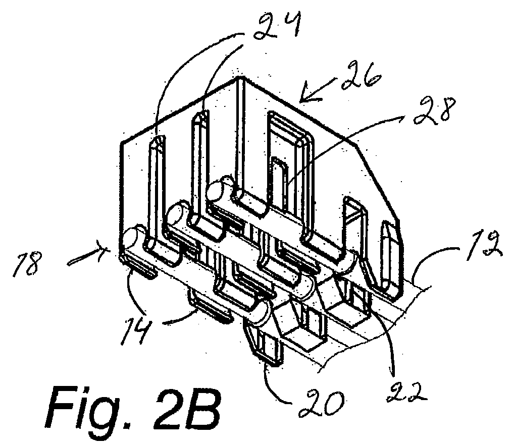
- Figs. 2A-C illustrate a connecting means of the invention along with its wires.
- Wires for electric lighting fixtures are generally set in place on an assembly line at the lighting fixture manufacturing plant or at a subcontractor of the lighting fixture manufacturing plant.
- the object is an electric lighting fixture or lamp, which is provided with a coupling device 2 for at least three wires to be connected to the lighting fixture, the total number of wires being seven in the subsequent example.
- the electric lighting fixture is for example an assembly consisting of the coupling device and the actual lamp member of a fluorescent lamp, which assembly is used for feeding electric current to fluorescent lamps.
- the coupling device may also be a mechanical inductor, which houses an iron core surrounded by a winding, such as for example a copper wiring.
- the coupling device comprises a standard-complying knife connector 4 and a circuit board with its components. Both the coupling device and the knife connector are shown in fig. 1 .
- the knife connector comprises typically side walls 6, at least one partition 8, and knife members 10 capable of cutting the wire insulation and retaining the wire in place.
- Depicted in fig. 1 is also a connecting means 11 according to the invention, by which the wires are clamped in engagement with the knife connector 4 and thereby with the coupling device 2.
- Electric wires for example those made of copper, are formed on top of a conductive layer with a dielectric coating layer, typically of a plastic material. At places, where the wires are desired to establish a conductive contact, the dielectric coating layer is stripped off. In most cases, the stripping is performed on the ends of wires. However, the invention proposes an implementation in which the stripping process can be completely discarded, i.e. the wires can be non-stripped.
- FIG. 2A-2C Depicted in figs. 2A-2C is a connecting means according to a preferred embodiment of the invention for clamping three wires 12 to a coupling device 2 equipped with a knife connector 4.
- the wires 12 are pressed into the connecting means' gripper elements 20 and retainer elements 14, the latter comprising flexible-edge channels 18 capable of yielding as the wires are pressed into the retainer elements.
- the dielectric coating layers are preferably intact.
- the gripper elements comprise a sharp-edged rib member 22, which takes hold of the dielectric wire coating on either side of the wire, holding the wire stationary.
- the gripper element can have its width extended and provided with a second sharp-edged rib member 22 for ensuring a reliable hold of the wire.
- the gripper element's firm hold of the wire can be implemented also by configurations of other nature, such as for example by a slightly converging gap for pressing the wire securely therein.
- the connecting means comprises at least one partition slot 24, wherein a partition 8 of the knife connector is accommodated upon clamping the connecting means to the coupling device.
- the connecting means is provided with a clamping assembly 26, comprising knife connector slots 28 which are pressed, together with the wires 12, against knife members 10 upon engaging the clamping assembly with the knife connector.
- the knife connector slots 28 are provided with slide elements 30, made for example of a plastic material.
- a wire 12 present in the clamping assembly 26 works its way to a knife member 10 of the knife connector, cutting the dielectric and establishing a contact with a conductive portion.
- this process occurs simultaneously for at least three wires included in the connecting means.
- the connecting means also, along with the wires, remain in a permanent position in engagement with the coupling device of an electric lighting fixture.
- the dielectric wire coating is cut by knife members so as to establish a conductive contact with the coupling device.
- the process of cutting a dielectric coating can be effected by a sharp cutting member present in the slide element or elsewhere in the wire channel.
- the connecting means Since the connecting means is connected through the intermediary of the knife connector 4 to a circuit board of the coupling device 2 by a pressing motion, the result is a moment of force on the circuit board, said moment increasing as the number of wires 12 present in the connecting means increases.
- the number of wires in the connecting means is not more than four in order to avoid a risk of breaking the circuit board due to an excessively great moment of force. If the circuit board is verified to have extra sturdiness, the connecting means and the number of wires can be increased accordingly.
Landscapes
- Multi-Conductor Connections (AREA)
- Arrangement Of Elements, Cooling, Sealing, Or The Like Of Lighting Devices (AREA)
- Connections By Means Of Piercing Elements, Nuts, Or Screws (AREA)
Abstract

Description
- Electric lighting fixtures are supplied with electric power required therefor by way of wires from an electric power source, such as the mains.
- Wires are connected to electric lighting fixtures by way of a coupling device. The coupling device comprises typically a so-called knife connector for clamping the wires therein.
Fig. 1 shows a coupling device 2 and a knife connector 4 of the prior art. - In a prior art type of connection, the wires are each clamped to coupling devices one wire at a time. A drawback in the discussed type of connection is that clamping a multitude of wires one by one is a highly time-consuming process.
- By virtue of the invention there is provided a means which enables connecting simultaneously several wires to electric lighting fixtures. The invention relates to a connecting means for clamping wires to a coupling device equipped with a knife connector. The connecting means comprises at least one retainer element for each wire for holding the wire in the retainer element, at least one gripper element as per each wire, said gripper element taking hold of a dielectric wire coating, at least one partition slot for at least one partition of the knife connector, and a clamping assembly for engaging the connecting means with the knife connector, such that the wires present in the connecting means are engaged in contact with the coupling device.
- The invention is based on a capability of setting two, preferably three or four wires, by using the connecting means' gripper element and retainer element, in engagement with the connecting means, by means of which the wires are quickly engageable with the coupling device of an electric lighting fixture on the basis of a compatible matching relationship between a clamping assembly included in the connecting means and a knife connector included in the coupling device.
- An advantage offered by the invention is the ability to connect a number of wires quickly and simultaneously to an electric lighting fixture during the installation process of lighting fixture wires.
-
Fig. 1 shows a lighting fixture coupling device of the prior art equipped with a knife connector, as well as a connecting means of the invention capable of mating therewith and including its wires. -
Figs. 2A-C illustrate a connecting means of the invention along with its wires. - Wires for electric lighting fixtures are generally set in place on an assembly line at the lighting fixture manufacturing plant or at a subcontractor of the lighting fixture manufacturing plant.
- In a preferred embodiment of the invention, the object is an electric lighting fixture or lamp, which is provided with a coupling device 2 for at least three wires to be connected to the lighting fixture, the total number of wires being seven in the subsequent example. The electric lighting fixture is for example an assembly consisting of the coupling device and the actual lamp member of a fluorescent lamp, which assembly is used for feeding electric current to fluorescent lamps. The coupling device may also be a mechanical inductor, which houses an iron core surrounded by a winding, such as for example a copper wiring. The coupling device comprises a standard-complying knife connector 4 and a circuit board with its components. Both the coupling device and the knife connector are shown in
fig. 1 . The knife connector comprises typically side walls 6, at least onepartition 8, andknife members 10 capable of cutting the wire insulation and retaining the wire in place. Depicted infig. 1 is also aconnecting means 11 according to the invention, by which the wires are clamped in engagement with the knife connector 4 and thereby with the coupling device 2. - Electric wires, for example those made of copper, are formed on top of a conductive layer with a dielectric coating layer, typically of a plastic material. At places, where the wires are desired to establish a conductive contact, the dielectric coating layer is stripped off. In most cases, the stripping is performed on the ends of wires. However, the invention proposes an implementation in which the stripping process can be completely discarded, i.e. the wires can be non-stripped.
- Depicted in
figs. 2A-2C is a connecting means according to a preferred embodiment of the invention for clamping threewires 12 to a coupling device 2 equipped with a knife connector 4. Thewires 12 are pressed into the connecting means'gripper elements 20 andretainer elements 14, the latter comprising flexible-edge channels 18 capable of yielding as the wires are pressed into the retainer elements. - In parts of the
wires 12 coinciding with thegripper elements 20, the dielectric coating layers are preferably intact. The gripper elements comprise a sharp-edgedrib member 22, which takes hold of the dielectric wire coating on either side of the wire, holding the wire stationary. The gripper element can have its width extended and provided with a second sharp-edged rib member 22 for ensuring a reliable hold of the wire. - The gripper element's firm hold of the wire can be implemented also by configurations of other nature, such as for example by a slightly converging gap for pressing the wire securely therein.
- The connecting means according to a preferred embodiment of the invention, shown in
fig. 2 , comprises at least onepartition slot 24, wherein apartition 8 of the knife connector is accommodated upon clamping the connecting means to the coupling device. The connecting means is provided with aclamping assembly 26, comprisingknife connector slots 28 which are pressed, together with thewires 12, againstknife members 10 upon engaging the clamping assembly with the knife connector. Theknife connector slots 28 are provided withslide elements 30, made for example of a plastic material. In the process of clamping the connecting means to the coupling device of an electric lighting fixture, awire 12 present in theclamping assembly 26 works its way to aknife member 10 of the knife connector, cutting the dielectric and establishing a contact with a conductive portion. In a preferred embodiment of the invention, this process occurs simultaneously for at least three wires included in the connecting means. In a preferred embodiment of the invention, the connecting means also, along with the wires, remain in a permanent position in engagement with the coupling device of an electric lighting fixture. - In the case of a non-stripped wire, the dielectric wire coating is cut by knife members so as to establish a conductive contact with the coupling device. Respectively, the process of cutting a dielectric coating can be effected by a sharp cutting member present in the slide element or elsewhere in the wire channel.
- Since the connecting means is connected through the intermediary of the knife connector 4 to a circuit board of the coupling device 2 by a pressing motion, the result is a moment of force on the circuit board, said moment increasing as the number of
wires 12 present in the connecting means increases. In a preferred embodiment of the invention, the number of wires in the connecting means is not more than four in order to avoid a risk of breaking the circuit board due to an excessively great moment of force. If the circuit board is verified to have extra sturdiness, the connecting means and the number of wires can be increased accordingly. - It is obvious that the foregoing exemplary embodiments are just examples of a wide range of possible implementations for the invention, nor is the scope of protection claimed for the invention limited to what is presented in these examples.
Claims (7)
- A connecting means for clamping wires (12) to an electric lighting fixture coupling device (2) equipped with a knife connector (4),
characterized in that the connecting means comprises:- at least one retainer element (14) for each wire for holding the wire in the retainer element,- at least one gripper element (20) as per each wire, said gripper element taking hold of a dielectric wire coating,- at least one partition slot (24), which is compatible for at least one partition (8) of the knife connector (4)- and a clamping assembly (26) for engaging the connecting means with the knife connector (4), such that the wires (12) present in the connecting means are engaged in contact with the coupling device (2) for transmitting electric power through the coupling device to an electric lighting fixture. - A connecting means as set forth in claim 1, characterized in that the retainer element (14) comprises a flexible-edge channel (18), by way of which the wire (12) is pressed into the retainer element.
- A connecting means as set forth in claim 1, characterized in that the clamping assembly (26) comprises knife connector slots (28) which are pressed, together with the wires (12), into the knife connector (4) upon engaging the clamping assembly with the knife connector.
- A connecting means as set forth in claim 3, characterized in that the knife connector (4) comprises knife members (10), which extend at least partially into the knife connector slots (28) included in the clamping assembly (26), such that, upon pressing the wires (12) into the knife connector slots in the process of making a connection, the knife members (10) establish contacts with a conductive portion of the wires.
- A connecting means as set forth in claim 4, characterized in that the wire slots (28) comprise slide elements (30), pushing the wires (12) to the knife members (10) upon engaging the clamping assembly (26) with the knife connector (4).
- A connecting means as set forth in claim 4, characterized in that the knife members (10) comprise at least two knives, extending on either side of the wires (12) at least partially into the knife connector slots (28) included in the clamping assembly (26) so as to establish contacts with a conductive portion of the wires.
- A connecting means as set forth in claim 1, characterized in that the gripper element (20) comprises a rib member (22), which grabs a hold of the dielectric coating of the wire (12).
Applications Claiming Priority (1)
| Application Number | Priority Date | Filing Date | Title |
|---|---|---|---|
| FI20070426A FI120608B (en) | 2007-05-30 | 2007-05-30 | Coupling means for coupling lighting devices |
Publications (2)
| Publication Number | Publication Date |
|---|---|
| EP1998416A2 true EP1998416A2 (en) | 2008-12-03 |
| EP1998416A3 EP1998416A3 (en) | 2010-05-26 |
Family
ID=38069465
Family Applications (1)
| Application Number | Title | Priority Date | Filing Date |
|---|---|---|---|
| EP08156158A Withdrawn EP1998416A3 (en) | 2007-05-30 | 2008-05-14 | Means for connecting wires of lamps |
Country Status (2)
| Country | Link |
|---|---|
| EP (1) | EP1998416A3 (en) |
| FI (1) | FI120608B (en) |
Family Cites Families (4)
| Publication number | Priority date | Publication date | Assignee | Title |
|---|---|---|---|---|
| DE3203651A1 (en) * | 1982-02-03 | 1983-08-18 | Maigler, geb. Maigler, Brigitta, 7100 Heilbronn | Plug connector and printed-circuit board/cable connector with insulation-piercing terminal contact connections for the connection of cables to a plurality of individual conductors which are mechanically independent of one another |
| JPH0629006U (en) * | 1992-09-14 | 1994-04-15 | 矢崎総業株式会社 | Insulation displacement connector |
| JP3223100B2 (en) * | 1996-03-01 | 2001-10-29 | 矢崎総業株式会社 | Cover structure of insulation displacement connector |
| US6592396B2 (en) * | 2001-01-12 | 2003-07-15 | Tyco Electronics Corp. | Cap for an electrical connector |
-
2007
- 2007-05-30 FI FI20070426A patent/FI120608B/en not_active IP Right Cessation
-
2008
- 2008-05-14 EP EP08156158A patent/EP1998416A3/en not_active Withdrawn
Also Published As
| Publication number | Publication date |
|---|---|
| FI20070426A0 (en) | 2007-05-30 |
| EP1998416A3 (en) | 2010-05-26 |
| FI120608B (en) | 2009-12-15 |
| FI20070426L (en) | 2008-12-01 |
Similar Documents
| Publication | Publication Date | Title |
|---|---|---|
| US7572976B1 (en) | Quick connect electrical box | |
| KR101853168B1 (en) | Terminal block with ground strap, spring force terminals, and screw lug terminal | |
| JP6466931B2 (en) | Terminal for contact with conductor | |
| US11509105B2 (en) | Connector with separable lacing fixture | |
| JP2004528692A (en) | Method and apparatus for using flat flexible cable connector | |
| CN102394402A (en) | Insulation displacement connector (IDC) | |
| US9912081B2 (en) | Lighted electrical connector housing | |
| US11936262B2 (en) | Electric motor and switching unit therefor | |
| US10057987B2 (en) | Printed circuit board with side access termination pads | |
| CN101420075B (en) | Flat multi-conductor cable connector | |
| WO2008137106A2 (en) | Insulation displacement crimp connector | |
| TW201212428A (en) | Coaxial connector and substrate connector | |
| US20200335891A1 (en) | Electric contacting device | |
| JPS6016707B2 (en) | electrical contacts | |
| CN102834976B (en) | There is the connection terminal of the device for cutting wire | |
| US4725247A (en) | Cable splicing assembly | |
| CN111602300B (en) | Wire-to-wire connection with insulation displacement connection contacts for integral strain relief | |
| CN102324334A (en) | Universal termination system for power tools | |
| US20070054540A1 (en) | Method of connecting a cable with an electrical connector | |
| JP2017508256A (en) | Surge protection device with at least one surge protection unit | |
| CN209374715U (en) | A kind of electric connector and lamps and lanterns | |
| CN112751222B (en) | Positioning orientation of wiring relative to electrical connector | |
| JP2014508383A (en) | Electrical connection parts | |
| KR200312218Y1 (en) | Switch connection wire | |
| CN109768408B (en) | Electric connector and lamp |
Legal Events
| Date | Code | Title | Description |
|---|---|---|---|
| PUAI | Public reference made under article 153(3) epc to a published international application that has entered the european phase |
Free format text: ORIGINAL CODE: 0009012 |
|
| AK | Designated contracting states |
Kind code of ref document: A2 Designated state(s): AT BE BG CH CY CZ DE DK EE ES FI FR GB GR HR HU IE IS IT LI LT LU LV MC MT NL NO PL PT RO SE SI SK TR |
|
| AX | Request for extension of the european patent |
Extension state: AL BA MK RS |
|
| PUAL | Search report despatched |
Free format text: ORIGINAL CODE: 0009013 |
|
| AK | Designated contracting states |
Kind code of ref document: A3 Designated state(s): AT BE BG CH CY CZ DE DK EE ES FI FR GB GR HR HU IE IS IT LI LT LU LV MC MT NL NO PL PT RO SE SI SK TR |
|
| AX | Request for extension of the european patent |
Extension state: AL BA MK RS |
|
| AKY | No designation fees paid | ||
| REG | Reference to a national code |
Ref country code: DE Ref legal event code: 8566 |
|
| STAA | Information on the status of an ep patent application or granted ep patent |
Free format text: STATUS: THE APPLICATION IS DEEMED TO BE WITHDRAWN |
|
| 18D | Application deemed to be withdrawn |
Effective date: 20101127 |