EP1998391A2 - Lithium secondary battery - Google Patents
Lithium secondary battery Download PDFInfo
- Publication number
- EP1998391A2 EP1998391A2 EP08251812A EP08251812A EP1998391A2 EP 1998391 A2 EP1998391 A2 EP 1998391A2 EP 08251812 A EP08251812 A EP 08251812A EP 08251812 A EP08251812 A EP 08251812A EP 1998391 A2 EP1998391 A2 EP 1998391A2
- Authority
- EP
- European Patent Office
- Prior art keywords
- electrode plate
- secondary battery
- electrode
- lithium secondary
- ceramic film
- Prior art date
- Legal status (The legal status is an assumption and is not a legal conclusion. Google has not performed a legal analysis and makes no representation as to the accuracy of the status listed.)
- Withdrawn
Links
Images


Classifications
-
- H—ELECTRICITY
- H01—ELECTRIC ELEMENTS
- H01M—PROCESSES OR MEANS, e.g. BATTERIES, FOR THE DIRECT CONVERSION OF CHEMICAL ENERGY INTO ELECTRICAL ENERGY
- H01M10/00—Secondary cells; Manufacture thereof
- H01M10/05—Accumulators with non-aqueous electrolyte
- H01M10/058—Construction or manufacture
- H01M10/0587—Construction or manufacture of accumulators having only wound construction elements, i.e. wound positive electrodes, wound negative electrodes and wound separators
-
- H—ELECTRICITY
- H01—ELECTRIC ELEMENTS
- H01M—PROCESSES OR MEANS, e.g. BATTERIES, FOR THE DIRECT CONVERSION OF CHEMICAL ENERGY INTO ELECTRICAL ENERGY
- H01M10/00—Secondary cells; Manufacture thereof
- H01M10/05—Accumulators with non-aqueous electrolyte
- H01M10/052—Li-accumulators
-
- H—ELECTRICITY
- H01—ELECTRIC ELEMENTS
- H01M—PROCESSES OR MEANS, e.g. BATTERIES, FOR THE DIRECT CONVERSION OF CHEMICAL ENERGY INTO ELECTRICAL ENERGY
- H01M10/00—Secondary cells; Manufacture thereof
- H01M10/04—Construction or manufacture in general
- H01M10/0431—Cells with wound or folded electrodes
-
- H—ELECTRICITY
- H01—ELECTRIC ELEMENTS
- H01M—PROCESSES OR MEANS, e.g. BATTERIES, FOR THE DIRECT CONVERSION OF CHEMICAL ENERGY INTO ELECTRICAL ENERGY
- H01M50/00—Constructional details or processes of manufacture of the non-active parts of electrochemical cells other than fuel cells, e.g. hybrid cells
- H01M50/40—Separators; Membranes; Diaphragms; Spacing elements inside cells
- H01M50/403—Manufacturing processes of separators, membranes or diaphragms
-
- H—ELECTRICITY
- H01—ELECTRIC ELEMENTS
- H01M—PROCESSES OR MEANS, e.g. BATTERIES, FOR THE DIRECT CONVERSION OF CHEMICAL ENERGY INTO ELECTRICAL ENERGY
- H01M50/00—Constructional details or processes of manufacture of the non-active parts of electrochemical cells other than fuel cells, e.g. hybrid cells
- H01M50/40—Separators; Membranes; Diaphragms; Spacing elements inside cells
- H01M50/409—Separators, membranes or diaphragms characterised by the material
- H01M50/446—Composite material consisting of a mixture of organic and inorganic materials
-
- H—ELECTRICITY
- H01—ELECTRIC ELEMENTS
- H01M—PROCESSES OR MEANS, e.g. BATTERIES, FOR THE DIRECT CONVERSION OF CHEMICAL ENERGY INTO ELECTRICAL ENERGY
- H01M50/00—Constructional details or processes of manufacture of the non-active parts of electrochemical cells other than fuel cells, e.g. hybrid cells
- H01M50/40—Separators; Membranes; Diaphragms; Spacing elements inside cells
- H01M50/46—Separators, membranes or diaphragms characterised by their combination with electrodes
-
- Y—GENERAL TAGGING OF NEW TECHNOLOGICAL DEVELOPMENTS; GENERAL TAGGING OF CROSS-SECTIONAL TECHNOLOGIES SPANNING OVER SEVERAL SECTIONS OF THE IPC; TECHNICAL SUBJECTS COVERED BY FORMER USPC CROSS-REFERENCE ART COLLECTIONS [XRACs] AND DIGESTS
- Y02—TECHNOLOGIES OR APPLICATIONS FOR MITIGATION OR ADAPTATION AGAINST CLIMATE CHANGE
- Y02E—REDUCTION OF GREENHOUSE GAS [GHG] EMISSIONS, RELATED TO ENERGY GENERATION, TRANSMISSION OR DISTRIBUTION
- Y02E60/00—Enabling technologies; Technologies with a potential or indirect contribution to GHG emissions mitigation
- Y02E60/10—Energy storage using batteries
-
- Y—GENERAL TAGGING OF NEW TECHNOLOGICAL DEVELOPMENTS; GENERAL TAGGING OF CROSS-SECTIONAL TECHNOLOGIES SPANNING OVER SEVERAL SECTIONS OF THE IPC; TECHNICAL SUBJECTS COVERED BY FORMER USPC CROSS-REFERENCE ART COLLECTIONS [XRACs] AND DIGESTS
- Y02—TECHNOLOGIES OR APPLICATIONS FOR MITIGATION OR ADAPTATION AGAINST CLIMATE CHANGE
- Y02P—CLIMATE CHANGE MITIGATION TECHNOLOGIES IN THE PRODUCTION OR PROCESSING OF GOODS
- Y02P70/00—Climate change mitigation technologies in the production process for final industrial or consumer products
- Y02P70/50—Manufacturing or production processes characterised by the final manufactured product
-
- Y—GENERAL TAGGING OF NEW TECHNOLOGICAL DEVELOPMENTS; GENERAL TAGGING OF CROSS-SECTIONAL TECHNOLOGIES SPANNING OVER SEVERAL SECTIONS OF THE IPC; TECHNICAL SUBJECTS COVERED BY FORMER USPC CROSS-REFERENCE ART COLLECTIONS [XRACs] AND DIGESTS
- Y10—TECHNICAL SUBJECTS COVERED BY FORMER USPC
- Y10T—TECHNICAL SUBJECTS COVERED BY FORMER US CLASSIFICATION
- Y10T29/00—Metal working
- Y10T29/49—Method of mechanical manufacture
- Y10T29/49002—Electrical device making
- Y10T29/49108—Electric battery cell making
- Y10T29/49115—Electric battery cell making including coating or impregnating
Definitions
- Embodiments of the present invention relate to a lithium secondary battery, and more particularly, to a lithium secondary battery in which safety is improved by preventing an internal short circuit.
- a secondary battery is capable of being recharged, miniaturized in size, and maximized in capacity.
- an improved secondary battery such as a lithium-ion battery, a lithium-polymer battery, and a Ni-MH battery
- a power supply has been widely developed as a power supply.
- lithium Since the atomic weight of lithium is low, lithium is appropriate for a large-electric capacity battery and is, therefore, frequently used as a component of a secondary battery. Furthermore, since lithium reacts fiercely with water, a non-aqueous electrolyte is also used in a lithium-based battery. Accordingly, the lithium is not affected by an electrolysis voltage of water, and thus, the lithium-based battery has an advantage of being able to generate approximately 3 to 4 volts of electro-motive force.
- the non-aqueous electrolyte used in the lithium-ion battery is classified into a liquid electrolyte and a solid electrolyte.
- the liquid electrolyte is an electrolyte in which lithium salt is dissociated into an organic solvent.
- Ethylene, carbonate, propylene carbonate, or other carbonates including alkyls or similar organic compounds can be used as the organic solvent.
- the ion conductivity of the electrolyte in the lithium-ion secondary battery is low.
- this defect can be overcome somewhat by increasing an active material area of the electrode and a size of opposing areas of both electrodes.
- increasing the size of opposing areas of both electrodes is limited due to various restrictive factors.
- the low ion conductivity of the electrolyte makes the internal impedance of the battery large in scale, thereby making the internal voltage drop large in scale. In particular, this is the reason to limit the current of the battery when a large current needs to be discharged, and thus restricts the output.
- a film positioned between two electrodes is another reason that the movement of lithium ions is confined.
- the film does not have sufficient permeability and wettability of the electrolyte, the film restricts the lithium ion from moving between two electrodes and, as a result, deteriorates electric characteristics of the battery.
- the features of the film in terms of the efficiency of the battery can be characterized not only by the heat/chemical resistance and the mechanical strength of the film, but also by the wettability of the electrolyte and the air-gap ratio (void content).
- the air-gap ratio refers to the proportion of the empty space per optionally sectioned surface of the film.
- the film of the lithium-ion battery is also a safety device that prevents the battery from overheating.
- the polyolefin micro-porous membrane which is a general material of a film, is softened and partly melted at a certain degree of temperature. Therefore, the minute through holes of the micro-porous membrane, which is the passage of the electrolyte and lithium ion, are subsequently blocked. As a result, the movement of lithium ion is stopped and the inner and outer current of the battery is stopped. Accordingly, the rising of temperature is also stopped.
- the film when the temperature of the battery rises, the film may become damaged even though the minute through holes are blocked. That is, as the film is partially melted, two electrodes of the battery may contact each other, causing an internal short circuit. The internal short circuit may also occur when the film is shrunk such that two electrodes of the battery contact each other as a result.
- the micro through holes of the film are blocked, an internal short circuit is more likely to occur due to damage to the film.
- the film may be damaged because the film continuously melts due to the generated heat, as opposed to lowering the temperature of the battery by blocking current.
- a ceramic film i.e., ceramic film
- the general manufacturing method of the ceramic film is as follows: first, a porous liquid is made wherein ceramic particles are evenly scattered into a mixed solution of the binder and the solvent; and an electrode plate, which is an electrode collector to which an active material is coated, is dipped into the porous liquid.
- Such ceramic film carries out the role of the functional membrane that prevents the short circuit of positive and negative electrode plates, the film being applied to the surface where the positive and negative electrode plates might contact each other.
- both ends of electrode plates in the ceramic film-coated secondary battery are cut off when manufacturing electrode plates.
- the cut-off parts of the electrode plates are not coated with the porous liquid. If the cut-off surfaces of the electrode plates that are not coated by the film are exposed to an outside, electrode plates having different polarities contact each other, and thus cause a short circuit when electrodes are laminated or spirally wound.
- aspects of the present invention improve the safety of a battery by reforming a winding shape of an electrode to which a ceramic film is applied.
- a battery including: an electrode assembly including a first electrode plate having a first polarity, a second electrode plate having a second polarity different from the first polarity, and a ceramic film provided on the first electrode plate; a can to house the electrode assembly and an electrolyte; and a cap assembly to seal an opening of the can, wherein the first electrode plate has a front edge positioned ahead of a front edge of the second electrode plate, and/or a back edge positioned behind a back edge of the second electrode plate.
- the first electrode plate and the second electrode plate may be laminated and/or spirally wound.
- the ceramic film may be a porous membrane including a combination of ceramic materials and a binder.
- One or more materials among silica (SiO 2 ) alumina (Al 2 0 3 ), zirconium oxide (ZrO 2 ) and titanium oxide (Ti02) may be used as the ceramic materials.
- At least one insulating material from among nitrides of silicon (Si), hydroxides of aluminum (AI), alkoxides of zirconium (Zr), and ketonic compounds of titanium (Ti) may be used as the ceramic materials.
- the ceramic film may be provided on the first electrode plate by dipping the first electrode plate into the binder and solvent mixed solution, spraying the mixed solution onto the electrode plate, and/or printing the mixed solution onto a front surface of the first electrode plate.
- the first electrode plate may be provided with the ceramic film on both surfaces thereof.
- the front edge of the first electrode plate may be spaced 10 mm or more from that of the second electrode plate and/or the back edge of the first electrode plate may be spaced 10 mm or more from that of the second electrode plate.
- the first electrode plate may be either the positive electrode plate or the negative electrode plate.
- an electrode assembly for a lithium secondary battery including: a first electrode plate having a first polarity; a second electrode plate having a second polarity different from the first polarity; and a ceramic film provided on the first electrode plate, wherein the first electrode plate has a front edge positioned ahead of a front edge of the second electrode plate, and/or a back edge positioned behind a back edge of the second electrode plate.
- a method of assembling electrode plates for a lithium secondary battery including: coating a first electrode plate having a first polarity with a ceramic film; and combining the first electrode plate with a second electrode plate having a second polarity different from the first polarity such that a front edge of the first electrode plate is ahead of a front edge of the second electrode plate and/or a back edge of the first electrode plate is behind a back edge of the second electrode plate.
- FIG. 1 is an exploded perspective view of a lithium-ion battery according to a preferred embodiment of the present invention.
- a lithium ion battery according to a preferred embodiment of the present invention includes: an electrode assembly 100 including electrode plates 110 and 120; a can 200 to house the electrode assembly 100; an electrolyte injected into the can 200 and acting as a mediator for passing lithium ions; and a cap assembly 300 to seal the opening of the can 200 housing the electrode assembly 100 and the electrolyte.
- the electrode assembly 100 includes: a positive electrode plate 110 in which positive electrode active materials are coated on a predetermined area of at least one surface thereof; a negative electrode plate 120 in which negative electrode active materials are coated on a predetermined area of at least one surface thereof; and a film 130 (i.e., film) located between the positive electrode plate and the negative electrode plate to prevent a short circuit therebetween and to pass lithium ions.
- a film 130 i.e., film
- the positive electrode plate 110 and the negative electrode plate 120 include an electrode collector and an electrode active material layer.
- the electrode active material layer may be manufactured as a slurry in which conducting materials, a bonding agent, and an organic solvent are mixed. Furthermore, the electrode active material layer is coated onto the electrode collector. Therefore, each of the positive and negative active materials is attached to the electrode collector by the bonding agent included therein to form an electrode active material layer.
- the film 130 is a ceramic film in which ceramic material is coated onto either the positive electrode plate 110 or the negative electrode plate 120.
- the film 130 may be coated with a different material with similar effect.
- the ceramic film 130 includes a porous membrane formed by combining the ceramic materials with the binder. Specifically, after a paste is made by mixing the ceramic material with the binder, the paste forms a porous membrane on the electrode plate. That is, a binder material, a solvent, and a ceramic powder are combined into a mixture liquid in order to form the porous membrane. Accordingly, the mixture liquid is coated onto the surface of the electrode plate to form the ceramic film 130.
- a binder material, a solvent, and a ceramic powder are combined into a mixture liquid in order to form the porous membrane. Accordingly, the mixture liquid is coated onto the surface of the electrode plate to form the ceramic film 130.
- methods of dipping the electrode plate into the binder-solvent mixed solution, spraying the mixed solution onto the electrode plate, and printing the mixed solution onto the electrode plate are applied.
- At least one among silica (SiO 2 ), alumina (Al 2 O 3 ), zirconium oxide (ZrO 2 ), and titanium oxide (TiO 2 ) may be used as the ceramic materials.
- at least one insulating material among nitrides of silicon (Si), hydroxides of aluminum (Al), alkoxides of zirconium (Zr), ketonic compounds of titanium (Ti) may be used as the ceramic materials.
- Si silica
- Al 2 O 3 zirconium oxide
- TiO 2 titanium oxide
- TiO 2 titanium oxide
- at least one insulating material among nitrides of silicon (Si), hydroxides of aluminum (Al), alkoxides of zirconium (Zr), ketonic compounds of titanium (Ti) may be used as the ceramic materials.
- aspects of the present invention are not limited to these materials.
- the cap assembly 300 which has a size corresponding to the opening of the can 200, includes: a cap plate 310 that has a terminal through hole 312 formed in the middle thereof and an electrolyte injection hole 314 formed in one side thereof; an electrode terminal 320 inserted into the terminal through hole 312; a gasket 330 interposed when the electrode terminal 320 is inserted into the terminal through hole 312; and an insulating plate 340 and a terminal plate 350 that are provided at a lower part of the cap plate 310.
- An insulating cover 400 may, although not necessarily, be mounted on an upper surface of the electrode assembly 100.
- the cut edges of the electrode plate 110 and 120 are not coated with the ceramic film 130 since the ceramic film 130 of the lithium secondary battery is coated on both sides of either the positive electrode plate 110 or the negative electrode plate 120 which have different polarities. Both edges of an electrode plate 110 and 120 that are exposed to an outside might contact the collector of the other electrode plate 110 and 120 that is not coated.
- the front edge of the ceramic film-coated electrode plate 110 and 120 is to be inserted and wound first, and the back edge of the ceramic film-coated electrode is to be wound later. This will be described in more detail with reference to FIGs. 2 4 .
- the electrode assembly 100 of the lithium secondary battery is in a state such that the negative electrode plate 120 is coated with the ceramic film 130.
- the front edge of the negative electrode plate 120 is wound first, and the front edge of the positive electrode plate 110 is wound afterwards. Then, since the front edge of the positive electrode plate 110 is located behind that of the negative electrode plate 120 (by a distance d1 illustrated in FIG. 3 ), a front edge part 122 that is cut off from the negative electrode plate 120 and is exposed to an outside does not contact the electrode collector of the positive electrode plate 110.
- the positive electrode plate 110 is wound first and is coated, and the front edge of the negative electrode plate 120 is located behind that of the positive electrode plate 110.
- the back edge of the negative electrode plate 120 is longer in length than that of the positive electrode plate 110 (by a distance d2 illustrated in FIG. 4 ). Therefore, the back edge part 124 that is cut-off from the negative electrode plate 120 and is exposed to an outside is located behind the electrode collector of the positive electrode plate 110. Accordingly, the back edge 124 of the negative electrode plate 120 does not contact the electrode collector of the positive electrode plate 110.
- the front edge of the positive electrode 110 is wound behind the front edge of the negative electrode plate 120 at, for example, an interval of at least 10 mm.
- the back edge of the positive electrode plate 110 is wound ahead of the back edge of the negative electrode plate 120 at, for example, an interval of at least 10 mm.
- the interval d between the front edge of the negative electrode plate 120 and the front edge of the positive electrode plate 100 or between the back edge of the positive electrode plate 110 and the back edge of the negative electrode plate 120 is, for example, 10 mm or more, the possibility that both ends of the negative electrode plate 120 contact the electrode collector of the positive electrode plate 110 can be eliminated, although the electrode assembly 100 is entirely expanded or shrunk when the battery is recharged or discharged. It is understood that a distance of more or less than 10 mm may be used as the reference distance, according to, for example, experimentation on the battery to determine a minimum distance to eliminate the chance of contact between both ends of the negative electrode plate 120 and the electrode collector of the positive electrode plate 110.
- the entire length of the ceramic film 130 coated negative electrode plate 120 may be longer than that of the positive electrode plate 110 in a horizontal direction.
- aspects of the present invention are not limited thereto.
- a length of the negative electrode plate 520 is equal to or shorter than that of the positive electrode plate 510. Accordingly, the negative electrode plate 520 of the lithium secondary battery 500 is wound before the positive electrode plate 510, and the front edge part 522 of the negative electrode plate 520 is positioned ahead of that of the positive electrode plate 510. Therefore, the front edge part 522 is exposed from the negative electrode plate 520 to an outside, but does not contact the electrode collector of the positive electrode plate 510.
- the back edge of the negative electrode plate 620 of the lithium secondary battery 600 is longer than that of the positive electrode plate 610 such that the negative electrode plate 620 is wound behind the back edge of the positive electrode plate 610. Therefore the back edge part 622 of the negative electrode plate 620 does not contact the electrode collector of the positive electrode plate 610.
- aspects of the present invention prevent an internal short circuit by winding the electrode plates such that the front edge of the ceramic film-coated electrode plate is located ahead of the front edge of the other electrode plate, and/or that the back edge of the ceramic film-coated electrode plate is located behind the back edge of the other electrode plate. Since the method of forming the ceramic film in the two embodiments illustrated in FIGs. 5 and 6 is the same as the configuration of the embodiment illustrated in FIG 1 , a description thereof will be omitted herein.
- aspects of the present invention have been described above wherein the negative electrode plate is coated with the ceramic film therein, aspects of the present invention may be applied wherein the ceramic film is coated onto the positive electrode plate.
- aspects of the present invention have been described with reference to a square type secondary battery, aspects of the present invention may be applied to a cylinder type secondary battery or a pouch type secondary battery in which the wound or laminated electrode assembly is used.
- aspects of the present invention may also be applied to an electrode assembly in which the electrode plate is laminated instead of wound, whereby the front edge part and/or the back edge part of the ceramic film-coated electrode is longer in length than those of the other electrode that is not coated with the ceramic film.
- the problem of a short circuit in a lithium secondary battery may be prevented, thereby improving a stability and a reliability of the battery.
Landscapes
- Chemical & Material Sciences (AREA)
- Chemical Kinetics & Catalysis (AREA)
- Electrochemistry (AREA)
- General Chemical & Material Sciences (AREA)
- Engineering & Computer Science (AREA)
- Manufacturing & Machinery (AREA)
- Composite Materials (AREA)
- Inorganic Chemistry (AREA)
- Materials Engineering (AREA)
- Secondary Cells (AREA)
- Cell Separators (AREA)
- Battery Electrode And Active Subsutance (AREA)
Abstract
Description
- Embodiments of the present invention relate to a lithium secondary battery, and more particularly, to a lithium secondary battery in which safety is improved by preventing an internal short circuit.
- Generally, a secondary battery is capable of being recharged, miniaturized in size, and maximized in capacity. Recently, as the demand for portable electronic apparatuses (such as camcorders, laptop computers, and a cell phones) has increased, an improved secondary battery (such as a lithium-ion battery, a lithium-polymer battery, and a Ni-MH battery) has been widely developed as a power supply.
- Since the atomic weight of lithium is low, lithium is appropriate for a large-electric capacity battery and is, therefore, frequently used as a component of a secondary battery. Furthermore, since lithium reacts fiercely with water, a non-aqueous electrolyte is also used in a lithium-based battery. Accordingly, the lithium is not affected by an electrolysis voltage of water, and thus, the lithium-based battery has an advantage of being able to generate approximately 3 to 4 volts of electro-motive force.
- The non-aqueous electrolyte used in the lithium-ion battery is classified into a liquid electrolyte and a solid electrolyte. The liquid electrolyte is an electrolyte in which lithium salt is dissociated into an organic solvent. Ethylene, carbonate, propylene carbonate, or other carbonates including alkyls or similar organic compounds can be used as the organic solvent.
- The ion conductivity of the electrolyte in the lithium-ion secondary battery is low. However, this defect can be overcome somewhat by increasing an active material area of the electrode and a size of opposing areas of both electrodes. However, increasing the size of opposing areas of both electrodes is limited due to various restrictive factors. After all, the low ion conductivity of the electrolyte makes the internal impedance of the battery large in scale, thereby making the internal voltage drop large in scale. In particular, this is the reason to limit the current of the battery when a large current needs to be discharged, and thus restricts the output.
- In addition, a film positioned between two electrodes is another reason that the movement of lithium ions is confined. In other words, when the film does not have sufficient permeability and wettability of the electrolyte, the film restricts the lithium ion from moving between two electrodes and, as a result, deteriorates electric characteristics of the battery.
- Therefore, the features of the film in terms of the efficiency of the battery can be characterized not only by the heat/chemical resistance and the mechanical strength of the film, but also by the wettability of the electrolyte and the air-gap ratio (void content). The air-gap ratio refers to the proportion of the empty space per optionally sectioned surface of the film.
- Meanwhile, the film of the lithium-ion battery is also a safety device that prevents the battery from overheating. Here, if the temperature is raised by an abnormality of the battery, the polyolefin micro-porous membrane, which is a general material of a film, is softened and partly melted at a certain degree of temperature. Therefore, the minute through holes of the micro-porous membrane, which is the passage of the electrolyte and lithium ion, are subsequently blocked. As a result, the movement of lithium ion is stopped and the inner and outer current of the battery is stopped. Accordingly, the rising of temperature is also stopped.
- However, when the temperature of the battery rises, the film may become damaged even though the minute through holes are blocked. That is, as the film is partially melted, two electrodes of the battery may contact each other, causing an internal short circuit. The internal short circuit may also occur when the film is shrunk such that two electrodes of the battery contact each other as a result.
- Moreover, when the capacity of the battery has been maximized and an over-current flows in the secondary battery, although the micro through holes of the film are blocked, an internal short circuit is more likely to occur due to damage to the film. The film may be damaged because the film continuously melts due to the generated heat, as opposed to lowering the temperature of the battery by blocking current.
- Therefore, while it is important to block current by closing the micro-pores of the film, coping with the melting or shrinking problem of the film caused by battery overheating may be more important.
- To deal with the problem above, a ceramic film (i.e., ceramic film) that prevents the internal short circuit between electrodes has been used. The general manufacturing method of the ceramic film is as follows: first, a porous liquid is made wherein ceramic particles are evenly scattered into a mixed solution of the binder and the solvent; and an electrode plate, which is an electrode collector to which an active material is coated, is dipped into the porous liquid. Such ceramic film carries out the role of the functional membrane that prevents the short circuit of positive and negative electrode plates, the film being applied to the surface where the positive and negative electrode plates might contact each other.
- However, both ends of electrode plates in the ceramic film-coated secondary battery are cut off when manufacturing electrode plates. The cut-off parts of the electrode plates are not coated with the porous liquid. If the cut-off surfaces of the electrode plates that are not coated by the film are exposed to an outside, electrode plates having different polarities contact each other, and thus cause a short circuit when electrodes are laminated or spirally wound.
- Aspects of the present invention improve the safety of a battery by reforming a winding shape of an electrode to which a ceramic film is applied.
- According to an aspect of the present invention, there is provided a battery including: an electrode assembly including a first electrode plate having a first polarity, a second electrode plate having a second polarity different from the first polarity, and a ceramic film provided on the first electrode plate; a can to house the electrode assembly and an electrolyte; and a cap assembly to seal an opening of the can, wherein the first electrode plate has a front edge positioned ahead of a front edge of the second electrode plate, and/or a back edge positioned behind a back edge of the second electrode plate.
- The first electrode plate and the second electrode plate may be laminated and/or spirally wound. Furthermore, the ceramic film may be a porous membrane including a combination of ceramic materials and a binder.
- One or more materials among silica (SiO2) alumina (Al203), zirconium oxide (ZrO2) and titanium oxide (Ti02) may be used as the ceramic materials.
- At least one insulating material from among nitrides of silicon (Si), hydroxides of aluminum (AI), alkoxides of zirconium (Zr), and ketonic compounds of titanium (Ti) may be used as the ceramic materials.
- The ceramic film may be provided on the first electrode plate by dipping the first electrode plate into the binder and solvent mixed solution, spraying the mixed solution onto the electrode plate, and/or printing the mixed solution onto a front surface of the first electrode plate.
- The first electrode plate may be provided with the ceramic film on both surfaces thereof.
- The front edge of the first electrode plate may be spaced 10 mm or more from that of the second electrode plate and/or the back edge of the first electrode plate may be spaced 10 mm or more from that of the second electrode plate.
- The first electrode plate may be either the positive electrode plate or the negative electrode plate.
- According to another aspect of the present invention, there is provided an electrode assembly for a lithium secondary battery, the electrode assembly including: a first electrode plate having a first polarity; a second electrode plate having a second polarity different from the first polarity; and a ceramic film provided on the first electrode plate, wherein the first electrode plate has a front edge positioned ahead of a front edge of the second electrode plate, and/or a back edge positioned behind a back edge of the second electrode plate.
- According to still another aspect of the present invention, there is provided a method of assembling electrode plates for a lithium secondary battery, the method including: coating a first electrode plate having a first polarity with a ceramic film; and combining the first electrode plate with a second electrode plate having a second polarity different from the first polarity such that a front edge of the first electrode plate is ahead of a front edge of the second electrode plate and/or a back edge of the first electrode plate is behind a back edge of the second electrode plate.
- Additional aspects and/or advantages of the invention will be set forth in part in the description which follows and, in part, will be obvious from the description, or may be learned by practice of the invention.
- These and/or other aspects and advantages of the invention will become apparent and more readily appreciated from the following description of the preferred embodiments described by way of example and taken in conjunction with the accompanying drawings of which:
-
FIG. 1 is an exploded perspective view of a lithium-ion battery according to a preferred embodiment of the present invention. -
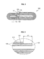
FIG. 2 is a plane view of which an electrode plate is wound in an electrode assembly shown inFIG. 1 . -
FIG. 3 is a magnified view of the part III ofFIG. 2 which illustrates the central part of the wound electrode assembly according to a preferred embodiment of the present invention. -
FIG. 4 is a magnified view of the part IV ofFIG. 2 which illustrates the outmost portion of the electrode assembly according to a preferred embodiment of the present invention. -
FIG. 5 is a plane view of an electrode assembly according to another preferred embodiment of the present invention. -
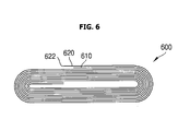
FIG. 6 is a plane view of an electrode assembly according to another preferred embodiment of the present invention. - Reference will now be made in detail to preferred embodiments of the present invention, examples of which are illustrated in the accompanying drawings, wherein like reference numerals refer to the like elements throughout. The embodiments are described below in order to explain the present invention by referring to the figures.
-
FIG. 1 is an exploded perspective view of a lithium-ion battery according to a preferred embodiment of the present invention. Referring toFIG. 1 , a lithium ion battery according to a preferred embodiment of the present invention includes: anelectrode assembly 100 includingelectrode plates electrode assembly 100; an electrolyte injected into thecan 200 and acting as a mediator for passing lithium ions; and acap assembly 300 to seal the opening of thecan 200 housing theelectrode assembly 100 and the electrolyte. Theelectrode assembly 100 includes: apositive electrode plate 110 in which positive electrode active materials are coated on a predetermined area of at least one surface thereof; anegative electrode plate 120 in which negative electrode active materials are coated on a predetermined area of at least one surface thereof; and a film 130 (i.e., film) located between the positive electrode plate and the negative electrode plate to prevent a short circuit therebetween and to pass lithium ions. - The
positive electrode plate 110 and thenegative electrode plate 120 include an electrode collector and an electrode active material layer. The electrode active material layer may be manufactured as a slurry in which conducting materials, a bonding agent, and an organic solvent are mixed. Furthermore, the electrode active material layer is coated onto the electrode collector. Therefore, each of the positive and negative active materials is attached to the electrode collector by the bonding agent included therein to form an electrode active material layer. - According to preferred embodiments of the present invention, the
film 130 is a ceramic film in which ceramic material is coated onto either thepositive electrode plate 110 or thenegative electrode plate 120. However, it is understood that aspects of the present invention are not limited thereto, and thefilm 130 may be coated with a different material with similar effect. - The
ceramic film 130 includes a porous membrane formed by combining the ceramic materials with the binder. Specifically, after a paste is made by mixing the ceramic material with the binder, the paste forms a porous membrane on the electrode plate. That is, a binder material, a solvent, and a ceramic powder are combined into a mixture liquid in order to form the porous membrane. Accordingly, the mixture liquid is coated onto the surface of the electrode plate to form theceramic film 130. In other words, to form the ceramic film on theelectrode plate - At least one among silica (SiO2), alumina (Al2O3), zirconium oxide (ZrO2), and titanium oxide (TiO2) may be used as the ceramic materials. In addition, at least one insulating material among nitrides of silicon (Si), hydroxides of aluminum (Al), alkoxides of zirconium (Zr), ketonic compounds of titanium (Ti) may be used as the ceramic materials. However, it is understood that aspects of the present invention are not limited to these materials.
- The
cap assembly 300, which has a size corresponding to the opening of thecan 200, includes: acap plate 310 that has a terminal throughhole 312 formed in the middle thereof and anelectrolyte injection hole 314 formed in one side thereof; anelectrode terminal 320 inserted into the terminal throughhole 312; agasket 330 interposed when theelectrode terminal 320 is inserted into the terminal throughhole 312; and an insulatingplate 340 and aterminal plate 350 that are provided at a lower part of thecap plate 310. An insulatingcover 400 may, although not necessarily, be mounted on an upper surface of theelectrode assembly 100. - According to a preferred embodiment of the present invention, when both edges of an
electrode plate electrode plate ceramic film 130 since theceramic film 130 of the lithium secondary battery is coated on both sides of either thepositive electrode plate 110 or thenegative electrode plate 120 which have different polarities. Both edges of anelectrode plate other electrode plate - Therefore, when the electrode plates are laminated or wound in a jelly-roll type, there is an increased possibility that both ends of the ceramic film-coated electrode plate contact the electrode collector of the other electrode plate that is not coated with the ceramic film. In fact, the possibility of an internal short circuit due to contact of both ends of an
electrode plate - According to preferred embodiments of the present invention, when the front edges of the
positive electrode plate 110 and thenegative electrode plate 120 are wound, the front edge of the ceramic film-coatedelectrode plate FIGs. 2 4 . - According to a preferred embodiment of the present invention, the
electrode assembly 100 of the lithium secondary battery is in a state such that thenegative electrode plate 120 is coated with theceramic film 130. During a winding of theelectrode assembly 100, as illustrated inFIG. 3 , the front edge of thenegative electrode plate 120 is wound first, and the front edge of thepositive electrode plate 110 is wound afterwards. Then, since the front edge of thepositive electrode plate 110 is located behind that of the negative electrode plate 120 (by a distance d1 illustrated inFIG. 3 ), afront edge part 122 that is cut off from thenegative electrode plate 120 and is exposed to an outside does not contact the electrode collector of thepositive electrode plate 110. It is understood that according to other aspects, thepositive electrode plate 110 is wound first and is coated, and the front edge of thenegative electrode plate 120 is located behind that of thepositive electrode plate 110. - Furthermore, once the winding is finished, as illustrated in
FIG. 4 , the back edge of thenegative electrode plate 120 is longer in length than that of the positive electrode plate 110 (by a distance d2 illustrated inFIG. 4 ). Therefore, theback edge part 124 that is cut-off from thenegative electrode plate 120 and is exposed to an outside is located behind the electrode collector of thepositive electrode plate 110. Accordingly, theback edge 124 of thenegative electrode plate 120 does not contact the electrode collector of thepositive electrode plate 110. - When the
electrode plates positive electrode 110 is wound behind the front edge of thenegative electrode plate 120 at, for example, an interval of at least 10 mm. Moreover, at the end point of winding, the back edge of thepositive electrode plate 110 is wound ahead of the back edge of thenegative electrode plate 120 at, for example, an interval of at least 10 mm. - As mentioned above, when the interval d between the front edge of the
negative electrode plate 120 and the front edge of thepositive electrode plate 100 or between the back edge of thepositive electrode plate 110 and the back edge of thenegative electrode plate 120 is, for example, 10 mm or more, the possibility that both ends of thenegative electrode plate 120 contact the electrode collector of thepositive electrode plate 110 can be eliminated, although theelectrode assembly 100 is entirely expanded or shrunk when the battery is recharged or discharged. It is understood that a distance of more or less than 10 mm may be used as the reference distance, according to, for example, experimentation on the battery to determine a minimum distance to eliminate the chance of contact between both ends of thenegative electrode plate 120 and the electrode collector of thepositive electrode plate 110. - Therefore, the entire length of the
ceramic film 130 coatednegative electrode plate 120 may be longer than that of thepositive electrode plate 110 in a horizontal direction. However, it is understood that aspects of the present invention are not limited thereto. - In other words, according to another preferred embodiment of the present invention (illustrated in
FIG. 5 ), a length of thenegative electrode plate 520 is equal to or shorter than that of thepositive electrode plate 510. Accordingly, thenegative electrode plate 520 of the lithiumsecondary battery 500 is wound before thepositive electrode plate 510, and thefront edge part 522 of thenegative electrode plate 520 is positioned ahead of that of thepositive electrode plate 510. Therefore, thefront edge part 522 is exposed from thenegative electrode plate 520 to an outside, but does not contact the electrode collector of thepositive electrode plate 510. - According to another preferred embodiment of the present invention (illustrated in
FIG.6 ), the back edge of thenegative electrode plate 620 of the lithiumsecondary battery 600 is longer than that of thepositive electrode plate 610 such that thenegative electrode plate 620 is wound behind the back edge of thepositive electrode plate 610. Therefore theback edge part 622 of thenegative electrode plate 620 does not contact the electrode collector of thepositive electrode plate 610. - Based on the foregoing, aspects of the present invention prevent an internal short circuit by winding the electrode plates such that the front edge of the ceramic film-coated electrode plate is located ahead of the front edge of the other electrode plate, and/or that the back edge of the ceramic film-coated electrode plate is located behind the back edge of the other electrode plate. Since the method of forming the ceramic film in the two embodiments illustrated in
FIGs. 5 and6 is the same as the configuration of the embodiment illustrated inFIG 1 , a description thereof will be omitted herein. - Although aspects of the present invention have been described above wherein the negative electrode plate is coated with the ceramic film therein, aspects of the present invention may be applied wherein the ceramic film is coated onto the positive electrode plate.
- Furthermore, although aspects of the present invention have been described with reference to a square type secondary battery, aspects of the present invention may be applied to a cylinder type secondary battery or a pouch type secondary battery in which the wound or laminated electrode assembly is used.
- In addition, aspects of the present invention may also be applied to an electrode assembly in which the electrode plate is laminated instead of wound, whereby the front edge part and/or the back edge part of the ceramic film-coated electrode is longer in length than those of the other electrode that is not coated with the ceramic film.
- As mentioned above, according to aspects of the present invention, the problem of a short circuit in a lithium secondary battery may be prevented, thereby improving a stability and a reliability of the battery.
- Although a few embodiments of the present invention have been shown and described, it would be appreciated by those skilled in the art that changes may be made without departing from the principles of the invention.
Claims (20)
- A lithium secondary battery, comprising:an electrode assembly comprising a first electrode plate having a first polarity, a second electrode plate having a second polarity different from the first polarity, and a ceramic film provided on the first electrode plate;a can to house the electrode assembly and an electrolyte; anda cap assembly to seal an opening of the can,wherein the first electrode plate has a front edge positioned ahead of a front edge of the second electrode plate, and/or a back edge positioned behind a back edge of the second electrode plate.
- The lithium secondary battery as claimed in claim 1, wherein the first electrode plate and the second electrode plate are laminated and/or spirally wound.
- The lithium secondary battery as claimed in claim 1, wherein the ceramic film is a porous membrane comprising a combination of ceramic materials and a binder.
- The lithium secondary battery as claimed in claim 3, wherein the ceramic materials are one or more materials from among silica (SiO2), alumina (Al203), zirconium oxide (ZrO2), and titanium oxide (TiO2).
- The lithium secondary battery as claimed in claim 3, wherein the ceramic materials are at least one insulating material from among nitrides of silicon (Si), hydroxides of aluminum (AI), alkoxides of zirconium (Zr), and ketonic compounds of titanium (Ti).
- The lithium secondary battery as claimed in any one of the preceding claims,
wherein the ceramic film is provided on the first electrode plate by dipping the first electrode plate into a solution mixed with the ceramic materials, the binder, and a solvent, by spraying the mixed solution onto the first electrode plate, and/or by printing the mixed solution onto a front surface of the first electrode plate. - The lithium secondary battery as claimed in any one of the preceding claims,
wherein the first electrode plate is provided with the ceramic film on both surfaces thereof. - The lithium secondary battery as claimed in any one of the preceding claims,
wherein the front edge of the first electrode plate is positioned at least 10 mm ahead of the front edge of the second electrode plate and/or the back edge of the first electrode plate is positioned at least 10 mm behind the back edge of the second electrode plate. - The lithium secondary battery as claimed in any one of the preceding claims,
wherein the first electrode plate is a negative electrode plate. - The lithium secondary battery as claimed in any one of claims 1 to 8,
wherein the first electrode plate is a positive electrode plate. - An electrode assembly for a lithium secondary battery, the electrode assembly comprising:a first electrode plate having a first polarity;a second electrode plate having a second polarity different from the first polarity; anda ceramic film provided on the first electrode plate,wherein the first electrode plate has a front edge positioned ahead of a front edge of the second electrode plate, and/or a back edge positioned behind a back edge of the second electrode plate.
- The electrode assembly as claimed in claim 11, wherein the ceramic film is a porous membrane comprising a combination of ceramic materials and a binder.
- The electrode assembly as claimed in any one of claims 11 or 12, wherein the ceramic film is provided on the first electrode plate by dipping the first electrode plate into a solution mixed with the ceramic materials, the binder, and a solvent, by spraying the mixed solution onto the first electrode plate, and/or by printing the mixed solution onto a front surface of the first electrode plate.
- The electrode assembly as claimed in any one of claims 11 to 13, wherein the first electrode plate is provided with the ceramic film on both surfaces thereof.
- A method of assembling electrode plates for a lithium secondary battery, the method comprising:coating a first electrode plate having a first polarity with a ceramic film; andcombining the first electrode plate with a second electrode plate having a second polarity different from the first polarity such that a front edge of the first electrode plate is ahead of a front edge of the second electrode plate and/or a back edge of the first electrode plate is behind a back edge of the second electrode plate.
- The method as claimed in claim 15, wherein the first electrode plate and the second electrode plate are laminated and/or spirally wound.
- The method as claimed in any one of claims 15 or 16, wherein the ceramic film is a porous membrane comprising a combination of ceramic materials and a binder.
- The method as claimed in claim 17, wherein the coating of the first electrode plate comprises dipping the first electrode plate into a solution mixed with the ceramic materials, the binder, and a solvent.
- The method as claimed in claim 17, wherein the coating of the first electrode plate comprises spraying a solution mixed with the ceramic materials, the binder, and a solvent onto the first electrode plate.
- The method as claimed in claim 17, wherein the coating of the first electrode plate comprises printing a solution mixed with the ceramic materials, the binder, and a solvent onto a front surface of the first electrode plate.
Applications Claiming Priority (1)
| Application Number | Priority Date | Filing Date | Title |
|---|---|---|---|
| KR1020070052175A KR100876271B1 (en) | 2007-05-29 | 2007-05-29 | Lithium secondary battery |
Publications (2)
| Publication Number | Publication Date |
|---|---|
| EP1998391A2 true EP1998391A2 (en) | 2008-12-03 |
| EP1998391A3 EP1998391A3 (en) | 2012-05-16 |
Family
ID=39746721
Family Applications (1)
| Application Number | Title | Priority Date | Filing Date |
|---|---|---|---|
| EP08251812A Withdrawn EP1998391A3 (en) | 2007-05-29 | 2008-05-23 | Lithium secondary battery |
Country Status (5)
| Country | Link |
|---|---|
| US (1) | US20080299454A1 (en) |
| EP (1) | EP1998391A3 (en) |
| JP (1) | JP4960892B2 (en) |
| KR (1) | KR100876271B1 (en) |
| CN (1) | CN101315992A (en) |
Cited By (2)
| Publication number | Priority date | Publication date | Assignee | Title |
|---|---|---|---|---|
| EP2079121A1 (en) * | 2008-01-11 | 2009-07-15 | Samsung SDI Co., Ltd. | Electrode Assembly and Secondary Battery having the same |
| US20240079565A1 (en) * | 2022-06-17 | 2024-03-07 | Contemporary Amperex Technology Co., Limited | Modified positive electrode material and preparation method thereof, positive electrode plate, secondary battery, battery module, battery pack and electrical apparatus |
Families Citing this family (6)
| Publication number | Priority date | Publication date | Assignee | Title |
|---|---|---|---|---|
| KR101090684B1 (en) | 2009-07-16 | 2011-12-08 | 에스케이이노베이션 주식회사 | Electrode assembly for battery and manufacturing thereof |
| DE102009041508A1 (en) * | 2009-09-14 | 2011-03-24 | Li-Tec Battery Gmbh | Electrochemical energy storage with a container |
| CN102484285B (en) * | 2009-09-28 | 2014-07-23 | 日立车辆能源株式会社 | Lithium-ion secondary battery |
| KR101084068B1 (en) | 2009-11-25 | 2011-11-16 | 삼성에스디아이 주식회사 | Lithium secondary battery |
| WO2018084675A1 (en) * | 2016-11-04 | 2018-05-11 | 주식회사 엘지화학 | Reaction estimation method for secondary battery and secondary battery comprising battery cell used for same |
| JP7579697B2 (en) * | 2020-12-24 | 2024-11-08 | 日本碍子株式会社 | Lithium-ion secondary battery |
Citations (4)
| Publication number | Priority date | Publication date | Assignee | Title |
|---|---|---|---|---|
| US6664006B1 (en) * | 1999-09-02 | 2003-12-16 | Lithium Power Technologies, Inc. | All-solid-state electrochemical device and method of manufacturing |
| KR20060053245A (en) | 2004-10-13 | 2006-05-19 | 모노리틱 파워 시스템즈 | How to Drive and Protect Discharge Lamps in Large Panel Applications |
| US20060115736A1 (en) | 2004-11-08 | 2006-06-01 | Fumiko Hashimoto | Secondary battery |
| US20120003546A1 (en) | 2004-11-17 | 2012-01-05 | Won Chull Han | Lithium ion secondary battery |
Family Cites Families (12)
| Publication number | Priority date | Publication date | Assignee | Title |
|---|---|---|---|---|
| CN1139142C (en) * | 1997-02-28 | 2004-02-18 | 旭化成株式会社 | Nonaqueous secondary battery and method for manufacturing same |
| JP2000030744A (en) * | 1998-07-14 | 2000-01-28 | Ngk Insulators Ltd | Lithium secondary battery |
| US20060105244A1 (en) * | 2002-06-08 | 2006-05-18 | Kejha Joseph B | Lithium based electrochemical devices having a ceramic separator glued therein by an ion conductive adhesive |
| JP4072427B2 (en) * | 2002-12-13 | 2008-04-09 | シャープ株式会社 | Polymer battery and manufacturing method thereof |
| JP2004342478A (en) * | 2003-05-16 | 2004-12-02 | Toshiba Battery Co Ltd | Flat type non-aqueous electrolyte secondary battery |
| JP2005012128A (en) * | 2003-06-20 | 2005-01-13 | Tdk Corp | Electrochemical device |
| WO2005067080A1 (en) * | 2004-01-09 | 2005-07-21 | Matsushita Electric Industrial Co., Ltd. | Lithium ion secondary cell |
| JP4617682B2 (en) * | 2004-02-20 | 2011-01-26 | パナソニック株式会社 | Lithium ion battery |
| US8778529B2 (en) * | 2004-11-29 | 2014-07-15 | Samsung Sdi Co., Ltd. | Lithium secondary battery |
| US7993777B2 (en) * | 2004-11-29 | 2011-08-09 | Samsung Sdi Co., Ltd. | Lithium secondary battery |
| JP2006228651A (en) * | 2005-02-21 | 2006-08-31 | Sanyo Electric Co Ltd | Nonaqueous electrolyte secondary battery and its charging method |
| EP1753122A1 (en) * | 2005-08-12 | 2007-02-14 | Nederlandse Organisatie voor toegepast-natuurwetenschappelijk Onderzoek TNO | Movement platform for carrier with five degrees of freedom |
-
2007
- 2007-05-29 KR KR1020070052175A patent/KR100876271B1/en active Active
-
2008
- 2008-01-10 JP JP2008003533A patent/JP4960892B2/en active Active
- 2008-02-20 US US12/034,094 patent/US20080299454A1/en not_active Abandoned
- 2008-05-23 EP EP08251812A patent/EP1998391A3/en not_active Withdrawn
- 2008-05-23 CN CNA2008100983407A patent/CN101315992A/en active Pending
Patent Citations (4)
| Publication number | Priority date | Publication date | Assignee | Title |
|---|---|---|---|---|
| US6664006B1 (en) * | 1999-09-02 | 2003-12-16 | Lithium Power Technologies, Inc. | All-solid-state electrochemical device and method of manufacturing |
| KR20060053245A (en) | 2004-10-13 | 2006-05-19 | 모노리틱 파워 시스템즈 | How to Drive and Protect Discharge Lamps in Large Panel Applications |
| US20060115736A1 (en) | 2004-11-08 | 2006-06-01 | Fumiko Hashimoto | Secondary battery |
| US20120003546A1 (en) | 2004-11-17 | 2012-01-05 | Won Chull Han | Lithium ion secondary battery |
Cited By (2)
| Publication number | Priority date | Publication date | Assignee | Title |
|---|---|---|---|---|
| EP2079121A1 (en) * | 2008-01-11 | 2009-07-15 | Samsung SDI Co., Ltd. | Electrode Assembly and Secondary Battery having the same |
| US20240079565A1 (en) * | 2022-06-17 | 2024-03-07 | Contemporary Amperex Technology Co., Limited | Modified positive electrode material and preparation method thereof, positive electrode plate, secondary battery, battery module, battery pack and electrical apparatus |
Also Published As
| Publication number | Publication date |
|---|---|
| JP4960892B2 (en) | 2012-06-27 |
| JP2008300349A (en) | 2008-12-11 |
| CN101315992A (en) | 2008-12-03 |
| US20080299454A1 (en) | 2008-12-04 |
| EP1998391A3 (en) | 2012-05-16 |
| KR100876271B1 (en) | 2008-12-26 |
Similar Documents
| Publication | Publication Date | Title |
|---|---|---|
| KR100646535B1 (en) | Electrode assembly for lithium ion battery and lithium ion secondary battery using same | |
| JP4594269B2 (en) | Lithium secondary battery {Lithium secondary battery} | |
| CN101312244B (en) | Electrode assembly and secondary battery using the electrode assembly | |
| JP5281836B2 (en) | Electrode assembly and secondary battery using the same | |
| EP1998391A2 (en) | Lithium secondary battery | |
| KR101914567B1 (en) | Secondary battery | |
| US8530077B2 (en) | Insulating case for secondary battery and secondary battery having the same | |
| JP2009094068A (en) | Lithium secondary battery | |
| KR100973309B1 (en) | Insulation case for secondary battery and secondary battery having same | |
| KR20090108418A (en) | Protective circuit assembly and battery pack having same | |
| CN111725473A (en) | Secondary battery | |
| US7985498B2 (en) | Lithium secondary battery | |
| KR100696791B1 (en) | Cap assembly and a lithium ion secondary battery having the same | |
| KR20110087559A (en) | An electrode assembly, a method of manufacturing the electrode assembly, and a secondary battery comprising the electrode assembly | |
| KR100824851B1 (en) | Electrode assembly and secondary battery having same | |
| JP2018045846A (en) | Electricity storage element | |
| KR100467702B1 (en) | Prismatic type lithium secondary battery | |
| KR100635734B1 (en) | Lithium ion battery | |
| KR100788559B1 (en) | Secondary battery | |
| CN110534799B (en) | Battery and battery cover plate assembly | |
| KR20080095465A (en) | Jelly roll type electrode assembly and secondary battery having same | |
| US20250349999A1 (en) | Integrated terminal, secondary battery including the same, and method of manufacturing the same | |
| KR100731464B1 (en) | Secondary Battery and Manufacturing Method of Secondary Battery Using the Same | |
| JP2010080390A (en) | Battery | |
| KR100833765B1 (en) | Lithium ion battery |
Legal Events
| Date | Code | Title | Description |
|---|---|---|---|
| PUAI | Public reference made under article 153(3) epc to a published international application that has entered the european phase |
Free format text: ORIGINAL CODE: 0009012 |
|
| 17P | Request for examination filed |
Effective date: 20080603 |
|
| AK | Designated contracting states |
Kind code of ref document: A2 Designated state(s): AT BE BG CH CY CZ DE DK EE ES FI FR GB GR HR HU IE IS IT LI LT LU LV MC MT NL NO PL PT RO SE SI SK TR |
|
| AX | Request for extension of the european patent |
Extension state: AL BA MK RS |
|
| PUAL | Search report despatched |
Free format text: ORIGINAL CODE: 0009013 |
|
| AK | Designated contracting states |
Kind code of ref document: A3 Designated state(s): AT BE BG CH CY CZ DE DK EE ES FI FR GB GR HR HU IE IS IT LI LT LU LV MC MT NL NO PL PT RO SE SI SK TR |
|
| AX | Request for extension of the european patent |
Extension state: AL BA MK RS |
|
| RIC1 | Information provided on ipc code assigned before grant |
Ipc: H01M 10/04 20060101ALI20120412BHEP Ipc: H01M 2/16 20060101AFI20120412BHEP |
|
| 17Q | First examination report despatched |
Effective date: 20130103 |
|
| AKX | Designation fees paid |
Designated state(s): DE FR GB |
|
| STAA | Information on the status of an ep patent application or granted ep patent |
Free format text: STATUS: THE APPLICATION IS DEEMED TO BE WITHDRAWN |
|
| 18D | Application deemed to be withdrawn |
Effective date: 20140415 |