EP1998322A1 - Magnetic disk for hard disk drives - Google Patents
Magnetic disk for hard disk drives Download PDFInfo
- Publication number
- EP1998322A1 EP1998322A1 EP08009748A EP08009748A EP1998322A1 EP 1998322 A1 EP1998322 A1 EP 1998322A1 EP 08009748 A EP08009748 A EP 08009748A EP 08009748 A EP08009748 A EP 08009748A EP 1998322 A1 EP1998322 A1 EP 1998322A1
- Authority
- EP
- European Patent Office
- Prior art keywords
- magnetic
- magnetic disk
- layer
- substrate
- disk according
- Prior art date
- Legal status (The legal status is an assumption and is not a legal conclusion. Google has not performed a legal analysis and makes no representation as to the accuracy of the status listed.)
- Granted
Links
- 230000005291 magnetic effect Effects 0.000 title claims abstract description 148
- 239000000758 substrate Substances 0.000 claims abstract description 47
- 238000004519 manufacturing process Methods 0.000 claims abstract description 28
- 238000005461 lubrication Methods 0.000 claims description 14
- 238000000034 method Methods 0.000 claims description 13
- 238000010030 laminating Methods 0.000 claims description 10
- 239000000314 lubricant Substances 0.000 claims description 8
- 239000000696 magnetic material Substances 0.000 claims description 7
- 230000001788 irregular Effects 0.000 claims description 3
- 239000000463 material Substances 0.000 description 12
- 238000005516 engineering process Methods 0.000 description 5
- 238000005498 polishing Methods 0.000 description 5
- OKTJSMMVPCPJKN-UHFFFAOYSA-N Carbon Chemical compound [C] OKTJSMMVPCPJKN-UHFFFAOYSA-N 0.000 description 4
- 206010040844 Skin exfoliation Diseases 0.000 description 4
- 229910052799 carbon Inorganic materials 0.000 description 4
- 238000005229 chemical vapour deposition Methods 0.000 description 4
- 239000011521 glass Substances 0.000 description 4
- 239000011295 pitch Substances 0.000 description 4
- 238000004544 sputter deposition Methods 0.000 description 4
- 230000007797 corrosion Effects 0.000 description 3
- 238000005260 corrosion Methods 0.000 description 3
- 239000000126 substance Substances 0.000 description 3
- 229910045601 alloy Inorganic materials 0.000 description 2
- 239000000956 alloy Substances 0.000 description 2
- 238000005530 etching Methods 0.000 description 2
- 238000000992 sputter etching Methods 0.000 description 2
- 229910018575 Al—Ti Inorganic materials 0.000 description 1
- 229910017061 Fe Co Inorganic materials 0.000 description 1
- 229910001260 Pt alloy Inorganic materials 0.000 description 1
- PNEYBMLMFCGWSK-UHFFFAOYSA-N aluminium oxide Inorganic materials [O-2].[O-2].[O-2].[Al+3].[Al+3] PNEYBMLMFCGWSK-UHFFFAOYSA-N 0.000 description 1
- 229910052593 corundum Inorganic materials 0.000 description 1
- 230000002708 enhancing effect Effects 0.000 description 1
- 230000005294 ferromagnetic effect Effects 0.000 description 1
- -1 for example Substances 0.000 description 1
- 238000012986 modification Methods 0.000 description 1
- 230000004048 modification Effects 0.000 description 1
- 230000035699 permeability Effects 0.000 description 1
- 238000003860 storage Methods 0.000 description 1
- 229910001845 yogo sapphire Inorganic materials 0.000 description 1
Images





Classifications
-
- G—PHYSICS
- G11—INFORMATION STORAGE
- G11B—INFORMATION STORAGE BASED ON RELATIVE MOVEMENT BETWEEN RECORD CARRIER AND TRANSDUCER
- G11B5/00—Recording by magnetisation or demagnetisation of a record carrier; Reproducing by magnetic means; Record carriers therefor
- G11B5/84—Processes or apparatus specially adapted for manufacturing record carriers
- G11B5/855—Coating only part of a support with a magnetic layer
Definitions
- the present invention relates to a magnetic disk installed in a magnetic disk device, and more particularly, to a magnetic disk such as a discrete track medium and a patterned medium, and a manufacturing method thereof.
- a magnetic disk such as a discrete track medium and a patterned medium has been proposed for enhancing the recording density.
- the magnetic disk device using the aforementioned magnetic disk has further reduced the distance between the magnetic head and the magnetic disk, which is as narrow as the value around 10 nm or less. Meanwhile, the reduced distance between the magnetic head and the magnetic disk is likely to cause the collision therebetween.
- Japanese Unexamined Patent Application Publication No. 2006-147148 discloses the magnetic recording medium provided with plural recording tracks formed of the ferromagnetic members separately arranged on the soft magnetic layer on the non-magnetic substrate, each having a cross section protruding widthwise, and a carbon layer formed on the upper surface of the respective recording tracks and the soft magnetic layer between plural recording tracks such that the thickness of the carbon layer formed on the upper surface of the recording track is larger than that of the carbon layer formed on the soft magnetic layer between the plural recording tracks for forming the patterned medium with excellent durability capable of performing the high density recording.
- Japanese Unexamined Patent Application Publication No. 5-258291 discloses the discrete disk having the sliding portion and the storage portion of the head and the disk separated, in which the hill-like structure serving as the separated bulkhead and the sliding portion is formed of the non-magnetic material with high wear resistance which is different from the material for forming the substrate so as to enhance the durability of the disk against the continuous sliding operations of the head and the disk.
- the protrusion as the non-magnetic member is formed on the disk surface so as to project higher than the magnetic recording layer for preventing the contact between the magnetic head and the magnetic recording section of the magnetic disk.
- the protrusion is formed in the disk substrate. Even if the magnetic head collides against the protrusion, the structure prevents the protrusion from collapsing so as not to damage the magnetic recording layer.
- the substrate is processed to have the concave and convex portions on the surface such that the magnetic recording layer is formed to slightly project to be higher than the magnetic recording layer.
- the present invention provides the magnetic disk with high durability against the contact with the magnetic head.
- the improvement in the durability enhances the corrosion resistance so as to provide the magnetic disk with high reliability.
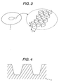
- Fig. 2 shows a structure of a substrate of a magnetic disk (discrete track medium) according to a first embodiment.
- a substrate 1 is formed as the non-magnetic substrate, for example, glass, and has concave and convex portions concentrically (annually) arranged each at the track pitch T.
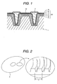
- Fig. 1 is a partially sectional view showing the state where the magnetic recording section and the protrusion are formed on a concave/convex surface of the substrate 1.
- the magnetic recording section is formed as a multi-layer film 20 formed by sequentially laminating an underlayer 2, a soft magnetic underlayer 3, an intermediate layer 4, a recording layer 5, and a hard overcoat 6 on the concave/convex surface of the substrate 1.
- a protrusion 7 is formed in the concave portion of the substrate 1 and the multi-layer film 20.
- a lubrication layer (overcoat) 8 is formed on the hard overcoat 6 and the protrusion 7.
- the protrusion 7 which is formed of the non-magnetic material projects to be 2nm to 10 nm higher than the magnetic recording section 10 interposed between the protrusions 7.
- the protrusion 7 serves to prevent the collision of the magnetic recording section 10 against the magnetic head. When the magnetic head collides against the protrusion 7 formed in the substrate 1, the protrusion 7 may be prevented from collapsing. This makes it possible to prevent the loss of the magnetically recorded data owing to deformation of the magnetic recording section 10.
- the interface of the protrusion 7 between different materials is formed at the single section between the protrusion 7 and the hard overcoat 6. This makes it possible to reduce the risk of peeling of the interface between the different materials compared with Japanese Unexamined Patent Application Publication No. 2006-147148 , resulting in the structure with excellent corrosion resistance.
- Fig. 3 shows the substrate structure of the patterned medium.
- a substrate 1' is a non-magnetic member likewise the one as described above, for example, the glass, which has concave and convex portions for forming the protrusions (irregular pattern) at track pitches T and bit cycles B.
- Structures of the multi-layer film 20 formed on the concave/convex surface of the substrate 1', and the protrusion 7 formed in the substrate 1' and the concave portion of the multi-layer film 20 are the same as those shown in Fig. 1 .
- the method for manufacturing the magnetic disk (discrete track medium) according to the first embodiment will be described.
- the concentric concave and convex portions are formed on the substrate 1 as the glass through the nanoimprint technology.
- the multi-layer film 20 is formed by sequentially laminating the underlayer 2, the soft magnetic underlayer 3, the intermediate layer 4, the recording layer 5 and the hard overcoat 6 through such film-forming process as sputtering and chemical vapor deposition.
- the underlayer 2 as the tight fit layer is preferably formed of the Al-Ti alloy.
- the soft magnetic underlayer 3 as the high permeability magnetic layer is preferably formed of the Fe-Co alloy.
- the intermediate layer 4 for subjecting the recording layer 5 to the epitaxial growing is preferably formed of Ru.
- the recording layer 5 as the magnetic recording layer is preferably formed of the Co-Cr-Pt alloy, for example.
- the hard overcoat 6 may be formed of the diamond-like carbon layer.
- a non-magnetic material 7' such as Al 2 O 3 is laminated through the film-forming process such as sputtering and chemical vapor deposition so as to mask the portion which is expected to be formed as the protrusion 7 with a resist film 9 as shown in Fig. 7 .
- etching such as the ion milling is performed to expose the portion to be formed as the magnetic recording section 10 as shown in Fig. 8 .
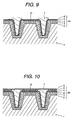
- the polishing is performed through the chemical mechanical polishing for adjusting the height of the protrusion 7 as shown in Fig. 9 .
- the protrusion 7 is formed to be 2 nm to 10 nm higher than the magnetic recording section 10.
- the lubricant is applied to form the lubrication layer (overcoat) 8 to form the structure as shown in Fig. 1 .
- perfluoroalkylpolyether may be used as the lubricant.
- the method for manufacturing the patterned medium is basically the same as the method for manufacturing the aforementioned discrete track medium except that the concave and convex portions are formed on the substrate.
- the concave and convex portions are formed on the substrate 1' as the glass through the nanoimprint technology such that the convex portions are regularly arranged each at the track pitch T and the bit cycle B.
- the multi-layer film 20 is formed on the concave/convex surface to form the protrusion 7 in the concave portion of the substrate 1' and the multi-layer film 20.
- the sectional structure is the same as the one shown in Fig. 1 .
- the lubrication layer (overcoat) 8 is formed on the concave/convex surface of the recording section 10 and the protrusion 7.
- the lubricant is applied to the recording section 10 to be substantially thicker than the other portion as shown in Fig. 10 such that the disk surface is flattened. In this case, as the disk surface is flat, the floating fluctuation of the magnetic head which is lifted above may be suppressed.
- the structure allows the magnetic head to perform the stable writing and reading.
- Fig. 11 shows the cross section of the essential portion of a magnetic disk according to a second embodiment.
- the magnetic disk according to the second embodiment includes a substrate 1 (1') with concentric concave and convex portions, or concave and convex portions having the convex portions regularly arranged at intervals each at the track pitch T and the bit cycle B, and a multi-layer film 20' formed by sequentially laminating the underlayer 2, the soft magnetic underlayer 3, the intermediate layer 4, and the recording layer 5.
- the protrusion 7 as the non-magnetic member is formed in the concave portion of the substrate 1(1').
- the hard overcoat 6 is laminated on the recording layer 5 and the protrusion 7.
- the lubrication layer 8 is further formed on the hard overcoat 6.
- the layer formed by laminating the hard overcoat 6 and the lubrication layer 8 will be referred to as an overcoat.
- the protrusion 7 projects to be 2nm to 10 nm higher than the recording section 10 interposed between the protrusions 7.
- the protrusion 7 prevents the recoding section 10 from being collided against the magnetic head.
- the protrusion 7 formed in the substrate 1 collides against the magnetic head, it does not collapse, and accordingly, the magnetic section 10 does not deform, thus preventing the loss of the magnetically recorded data.
- the protrusion 7 As the protrusion 7 is formed, two types of interface between different materials may be formed, that is, the one between the protrusion 7 and the hard overcoat 6, and the other between the protrusion 7 and the recording layer 5. Unlike Japanese Unexamined Patent Application Publication No. 2006-147148 , the risk of peeling of the interface between the different materials may be suppressed.
- the wear resistance of the protrusion 7 on which the hard overcoat 6 is formed may further be improved compared with the first embodiment.
- the concave and convex portions are formed on the substrate 1 (1') through the nanoimprint technology as shown in Fig. 2 in the same manner as in the first embodiment.
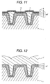
- the underlayer 2, the soft magnetic underlayer 3, the intermediate layer 4, the recording layer 5, and the non-magnetic material 7' are sequentially laminated through the film-forming process such as sputtering and chemical vapor deposition as shown in Fig. 12 .
- Each material for forming the underlayer 2, the soft magnetic underlayer 3, the intermediate layer 4, the recording layer 5, and the non-magnetic material 7' is the same as the one described in the first embodiment. Referring to Fig. 13 , the area to be formed as the protrusion 7 is masked with the resist film 9 and the like.
- etching such as the ion milling is performed to expose the magnetic recording section 10 as shown in Fig. 14 .
- the polishing such as chemical mechanical polishing is performed to adjust the height of the protrusion 7 as shown in Fig. 15 such that the protrusion 7 becomes higher than the recording section 10 by 2 nm to 10 nm.
- the hard overcoat 6 is laminated to cover the recording layer 5 and the protrusion 7 as shown in Fig. 16 .
- the lubrication layer 8 is formed by applying the lubricant to form the structure as shown in Fig. 11 .
- the lubricant may be applied to the magnetic recording section 10 to be relatively thicker than the other portion to flatten the disk surface likewise the first embodiment. This makes it possible to suppress the floating fluctuation of the magnetic head, thus allowing the magnetic head to perform the stable writing and reading.
- Fig. 18 shows the cross section of the essential portion of a magnetic disk according to a third embodiment.
- the magnetic disk according to the third embodiment includes a magnetic recording section 10' formed by laminating the underlayer 2, the soft magnetic underlayer 3, the intermediate layer 4, and the recording layer 5 sequentially in the concave portion on the concave/convex surface of the substrate 1 (1').
- the hard overcoat 6 is further laminated on the protrusion 7 as the convex portion of the substrate 1 and the magnetic recording section 10'.
- the lubrication layer 8 is further formed on the hard overcoat 6.
- the surface of the magnetic recording section 10' is formed to have the height lower than that of the protrusion 7.
- the protrusion 7 formed on the substrate 1 (1') prevents the collision between the magnetic recording section 10' and the magnetic head. When the protrusion 7 formed as the portion of the substrate 1 (1') collides against the magnetic head, it does not collapse, and accordingly, the recording section 10' is not deformed, thus preventing the loss of the magnetically recorded data
- Each corner 11 of the concave portion of the substrate 1 (1') is rounded to be curved so as to reduce the concentration of stress of the corner 11 resulting from the collision between the protrusion 7 and the magnetic head.
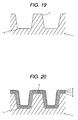
- the concave and convex portions are formed on the substrate 1 (1') through the nanoimprint technology as shown in Fig. 19 , and at the same time, each corner 11 of the concave portions is rounded to reduce the stress concentration.
- the underlayer 2, the soft magnetic underlayer 3, the intermediate layer 4, and the recording layer 5 are sequentially laminated through the film-forming process such as sputtering and chemical vapor deposition.
- the substrate surface is polished through the chemical mechanical polishing to form the protrusion 7 to be higher than the magnetic recording section 10' by 2 nm to 10 nm.
- the hard overcoat 6 is laminated to cover the protrusion 7 and the recording section 10' as shown in Fig. 22 .
- the lubricant is applied to form the lubrication layer 8 to produce the structure as shown in Fig. 18 .
- the lubricant may be applied to the magnetic recording section 10' to be relatively thicker than the other portion to flatten the disk surface as shown in Fig. 23 .
- the floating fluctuation of the magnetic head thus, may be suppressed, allowing the magnetic head to perform the stable writing and reading.
Landscapes
- Magnetic Record Carriers (AREA)
- Manufacturing Of Magnetic Record Carriers (AREA)
Abstract
Description
- The present invention relates to a magnetic disk installed in a magnetic disk device, and more particularly, to a magnetic disk such as a discrete track medium and a patterned medium, and a manufacturing method thereof.
- Recently, the attempt to introduce various types of technology has been made along with the trend of larger capacity and higher memory density of the magnetic disk device. For example, a magnetic disk such as a discrete track medium and a patterned medium has been proposed for enhancing the recording density. The magnetic disk device using the aforementioned magnetic disk has further reduced the distance between the magnetic head and the magnetic disk, which is as narrow as the value around 10 nm or less. Meanwhile, the reduced distance between the magnetic head and the magnetic disk is likely to cause the collision therebetween.
- Japanese Unexamined Patent Application Publication No.
2006-147148 - Japanese Unexamined Patent Application Publication No.
5-258291 - As described in Japanese Unexamined Patent Application Publication No.
2006-147148 - As described in Japanese Unexamined Patent Application Publication No.
5-258291 - It is an object of the present invention to provide a magnetic disk with a structure which prevents the magnetic recording section from being in contact with the magnetic head, and a method for manufacturing the magnetic disk.
- In the first aspect of the present invention, the protrusion as the non-magnetic member is formed on the disk surface so as to project higher than the magnetic recording layer for preventing the contact between the magnetic head and the magnetic recording section of the magnetic disk. In the second aspect of the present invention, the protrusion is formed in the disk substrate. Even if the magnetic head collides against the protrusion, the structure prevents the protrusion from collapsing so as not to damage the magnetic recording layer. The substrate is processed to have the concave and convex portions on the surface such that the magnetic recording layer is formed to slightly project to be higher than the magnetic recording layer.
- The present invention provides the magnetic disk with high durability against the contact with the magnetic head. The improvement in the durability enhances the corrosion resistance so as to provide the magnetic disk with high reliability.
-
-
Fig. 1 is a sectional view showing an essential portion of a magnetic disk according to a first embodiment; -
Fig. 2 is a view schematically showing a structure of a substrate of a discrete track medium; -
Fig. 3 is a view schematically showing a structure of a substrate of a patterned medium; -
Fig. 4 is a view showing a step of manufacturing the magnetic disk according to the first embodiment; -
Fig. 5 is a view showing the step of manufacturing the magnetic disk according to the first embodiment; -
Fig. 6 is a view showing the step of manufacturing the magnetic disk according to the first embodiment; -
Fig. 7 is a view showing the step of manufacturing the magnetic disk according to the first embodiment; -
Fig. 8 is a view showing the step of manufacturing the magnetic disk according to the first embodiment; -
Fig. 9 is a view showing the step of manufacturing the magnetic disk according to the first embodiment; -
Fig. 10 is a sectional view showing an essential portion of a modified example of the magnetic disk according to the first embodiment; -
Fig. 11 is a sectional view showing an essential portion of a magnetic disk according to a second embodiment; -
Fig. 12 is a view showing a step of manufacturing the magnetic disk according to the second embodiment; -
Fig. 13 is a view showing the step of manufacturing the magnetic disk according to the second embodiment; -
Fig. 14 is a view showing the step of manufacturing the magnetic disk according to the second embodiment; -
Fig. 15 is a view showing the step of manufacturing the magnetic disk according to the second embodiment; -
Fig. 16 is a view showing the step of manufacturing the magnetic disk according to the second embodiment; -
Fig. 17 is a sectional view showing an essential portion of a modified example of the magnetic disk according to the second embodiment; -
Fig. 18 is a sectional view showing an essential portion of a magnetic disk according to a third embodiment; -
Fig. 19 is a view showing a step of manufacturing the magnetic disk according to the third embodiment; -
Fig. 20 is a view showing the step of manufacturing the magnetic disk according to the third embodiment; -
Fig. 21 is a view showing the step of manufacturing the magnetic disk according to the third embodiment; -
Fig. 22 is a view showing the step of manufacturing the magnetic disk according to the third embodiment; and -
Fig. 23 is a sectional view showing an essential portion of the magnetic disk according to the third embodiment. - Embodiments will be described referring to the drawings.
-
Fig. 2 shows a structure of a substrate of a magnetic disk (discrete track medium) according to a first embodiment. Asubstrate 1 is formed as the non-magnetic substrate, for example, glass, and has concave and convex portions concentrically (annually) arranged each at the track pitch T.Fig. 1 is a partially sectional view showing the state where the magnetic recording section and the protrusion are formed on a concave/convex surface of thesubstrate 1. The magnetic recording section is formed as amulti-layer film 20 formed by sequentially laminating anunderlayer 2, a softmagnetic underlayer 3, anintermediate layer 4, arecording layer 5, and ahard overcoat 6 on the concave/convex surface of thesubstrate 1. Aprotrusion 7 is formed in the concave portion of thesubstrate 1 and themulti-layer film 20. A lubrication layer (overcoat) 8 is formed on thehard overcoat 6 and theprotrusion 7. Theprotrusion 7 which is formed of the non-magnetic material projects to be 2nm to 10 nm higher than themagnetic recording section 10 interposed between theprotrusions 7. Theprotrusion 7 serves to prevent the collision of themagnetic recording section 10 against the magnetic head. When the magnetic head collides against theprotrusion 7 formed in thesubstrate 1, theprotrusion 7 may be prevented from collapsing. This makes it possible to prevent the loss of the magnetically recorded data owing to deformation of themagnetic recording section 10. The interface of theprotrusion 7 between different materials is formed at the single section between theprotrusion 7 and thehard overcoat 6. This makes it possible to reduce the risk of peeling of the interface between the different materials compared with Japanese Unexamined Patent Application Publication No.2006-147148 -
Fig. 3 shows the substrate structure of the patterned medium. A substrate 1' is a non-magnetic member likewise the one as described above, for example, the glass, which has concave and convex portions for forming the protrusions (irregular pattern) at track pitches T and bit cycles B. Structures of themulti-layer film 20 formed on the concave/convex surface of the substrate 1', and theprotrusion 7 formed in the substrate 1' and the concave portion of themulti-layer film 20 are the same as those shown inFig. 1 . - Referring to
Figs. 4 to 9 , the method for manufacturing the magnetic disk (discrete track medium) according to the first embodiment will be described. As shown inFig. 4 , the concentric concave and convex portions are formed on thesubstrate 1 as the glass through the nanoimprint technology. Referring toFig. 5 , themulti-layer film 20 is formed by sequentially laminating theunderlayer 2, the softmagnetic underlayer 3, theintermediate layer 4, therecording layer 5 and thehard overcoat 6 through such film-forming process as sputtering and chemical vapor deposition. Theunderlayer 2 as the tight fit layer is preferably formed of the Al-Ti alloy. The softmagnetic underlayer 3 as the high permeability magnetic layer is preferably formed of the Fe-Co alloy. Theintermediate layer 4 for subjecting therecording layer 5 to the epitaxial growing is preferably formed of Ru. Therecording layer 5 as the magnetic recording layer is preferably formed of the Co-Cr-Pt alloy, for example. Thehard overcoat 6 may be formed of the diamond-like carbon layer. Referring toFig. 6 , a non-magnetic material 7' such as Al2O3 is laminated through the film-forming process such as sputtering and chemical vapor deposition so as to mask the portion which is expected to be formed as theprotrusion 7 with a resistfilm 9 as shown inFig. 7 . Then etching such as the ion milling is performed to expose the portion to be formed as themagnetic recording section 10 as shown inFig. 8 . The polishing is performed through the chemical mechanical polishing for adjusting the height of theprotrusion 7 as shown inFig. 9 . Theprotrusion 7 is formed to be 2 nm to 10 nm higher than themagnetic recording section 10. Finally, the lubricant is applied to form the lubrication layer (overcoat) 8 to form the structure as shown inFig. 1 . As the lubricant, perfluoroalkylpolyether may be used. - The method for manufacturing the patterned medium is basically the same as the method for manufacturing the aforementioned discrete track medium except that the concave and convex portions are formed on the substrate. Referring to
Fig. 3 , the concave and convex portions are formed on the substrate 1' as the glass through the nanoimprint technology such that the convex portions are regularly arranged each at the track pitch T and the bit cycle B. Referring toFigs. 5 to 9 , themulti-layer film 20 is formed on the concave/convex surface to form theprotrusion 7 in the concave portion of the substrate 1' and themulti-layer film 20. The sectional structure is the same as the one shown inFig. 1 . - In the first embodiment, the lubrication layer (overcoat) 8 is formed on the concave/convex surface of the
recording section 10 and theprotrusion 7. The lubricant is applied to therecording section 10 to be substantially thicker than the other portion as shown inFig. 10 such that the disk surface is flattened. In this case, as the disk surface is flat, the floating fluctuation of the magnetic head which is lifted above may be suppressed. The structure allows the magnetic head to perform the stable writing and reading. -
Fig. 11 shows the cross section of the essential portion of a magnetic disk according to a second embodiment. The magnetic disk according to the second embodiment includes a substrate 1 (1') with concentric concave and convex portions, or concave and convex portions having the convex portions regularly arranged at intervals each at the track pitch T and the bit cycle B, and a multi-layer film 20' formed by sequentially laminating theunderlayer 2, the softmagnetic underlayer 3, theintermediate layer 4, and therecording layer 5. Theprotrusion 7 as the non-magnetic member is formed in the concave portion of the substrate 1(1'). Thehard overcoat 6 is laminated on therecording layer 5 and theprotrusion 7. Thelubrication layer 8 is further formed on thehard overcoat 6. In the second embodiment, the layer formed by laminating thehard overcoat 6 and thelubrication layer 8 will be referred to as an overcoat. Theprotrusion 7 projects to be 2nm to 10 nm higher than therecording section 10 interposed between theprotrusions 7. In the aforementioned structure, theprotrusion 7 prevents therecoding section 10 from being collided against the magnetic head. When theprotrusion 7 formed in thesubstrate 1 collides against the magnetic head, it does not collapse, and accordingly, themagnetic section 10 does not deform, thus preventing the loss of the magnetically recorded data. As theprotrusion 7 is formed, two types of interface between different materials may be formed, that is, the one between theprotrusion 7 and thehard overcoat 6, and the other between theprotrusion 7 and therecording layer 5. Unlike Japanese Unexamined Patent Application Publication No.2006-147148 protrusion 7 on which thehard overcoat 6 is formed may further be improved compared with the first embodiment. - In the manufacturing method according to the second embodiment, the concave and convex portions are formed on the substrate 1 (1') through the nanoimprint technology as shown in
Fig. 2 in the same manner as in the first embodiment. Then theunderlayer 2, the softmagnetic underlayer 3, theintermediate layer 4, therecording layer 5, and the non-magnetic material 7' are sequentially laminated through the film-forming process such as sputtering and chemical vapor deposition as shown inFig. 12 . Each material for forming theunderlayer 2, the softmagnetic underlayer 3, theintermediate layer 4, therecording layer 5, and the non-magnetic material 7' is the same as the one described in the first embodiment. Referring toFig. 13 , the area to be formed as theprotrusion 7 is masked with the resistfilm 9 and the like. Then etching such as the ion milling is performed to expose themagnetic recording section 10 as shown inFig. 14 . The polishing such as chemical mechanical polishing is performed to adjust the height of theprotrusion 7 as shown inFig. 15 such that theprotrusion 7 becomes higher than therecording section 10 by 2 nm to 10 nm. Then thehard overcoat 6 is laminated to cover therecording layer 5 and theprotrusion 7 as shown inFig. 16 . Finally, thelubrication layer 8 is formed by applying the lubricant to form the structure as shown inFig. 11 . - In the second embodiment, as shown in
Fig. 17 , the lubricant may be applied to themagnetic recording section 10 to be relatively thicker than the other portion to flatten the disk surface likewise the first embodiment. This makes it possible to suppress the floating fluctuation of the magnetic head, thus allowing the magnetic head to perform the stable writing and reading. Third embodiment -
Fig. 18 shows the cross section of the essential portion of a magnetic disk according to a third embodiment. The magnetic disk according to the third embodiment includes a magnetic recording section 10' formed by laminating theunderlayer 2, the softmagnetic underlayer 3, theintermediate layer 4, and therecording layer 5 sequentially in the concave portion on the concave/convex surface of the substrate 1 (1'). Thehard overcoat 6 is further laminated on theprotrusion 7 as the convex portion of thesubstrate 1 and the magnetic recording section 10'. Thelubrication layer 8 is further formed on thehard overcoat 6. The surface of the magnetic recording section 10' is formed to have the height lower than that of theprotrusion 7. Theprotrusion 7 formed on the substrate 1 (1') prevents the collision between the magnetic recording section 10' and the magnetic head.
When theprotrusion 7 formed as the portion of the substrate 1 (1') collides against the magnetic head, it does not collapse, and accordingly, the recording section 10' is not deformed, thus preventing the loss of the magnetically recorded data. - Each
corner 11 of the concave portion of the substrate 1 (1') is rounded to be curved so as to reduce the concentration of stress of thecorner 11 resulting from the collision between theprotrusion 7 and the magnetic head. - In the manufacturing method, the concave and convex portions are formed on the substrate 1 (1') through the nanoimprint technology as shown in
Fig. 19 , and at the same time, eachcorner 11 of the concave portions is rounded to reduce the stress concentration. Then as shown inFig. 20 , theunderlayer 2, the softmagnetic underlayer 3, theintermediate layer 4, and therecording layer 5 are sequentially laminated through the film-forming process such as sputtering and chemical vapor deposition. Then as shown inFig. 21 , the substrate surface is polished through the chemical mechanical polishing to form theprotrusion 7 to be higher than the magnetic recording section 10' by 2 nm to 10 nm. Then thehard overcoat 6 is laminated to cover theprotrusion 7 and the recording section 10' as shown inFig. 22 . Finally, the lubricant is applied to form thelubrication layer 8 to produce the structure as shown inFig. 18 . - In the third embodiment, the lubricant may be applied to the magnetic recording section 10' to be relatively thicker than the other portion to flatten the disk surface as shown in
Fig. 23 . The floating fluctuation of the magnetic head, thus, may be suppressed, allowing the magnetic head to perform the stable writing and reading. Features, components and specific details of the structures of the above-described embodiments may be exchanged or combined to form further embodiments optimized for the respective application. As far as those modifications are readily apparent for an expert skilled in the art they shall be disclosed implicitly by the above description without specifying explicitly every possible combination, for the sake of conciseness of the present description.
Claims (20)
- A magnetic disk comprising:a substrate having annular convex and concave portions;a magnetic recording section formed on at least the convex portion on the substrate;a protrusion formed of a non-magnetic material, which is formed in the concave portion of the substrate and projects to be higher than a surface of the magnetic recording section; andan overcoat which covers the magnetic recording section and the protrusion.
- The magnetic disk according to claim 1, wherein the convex portions form an irregular pattern separated in a circumferential direction of the substrate.
- The magnetic disk according to claim 1 or 2, wherein the protrusion projects to be 2 nm to 10 nm higher than the magnetic recording section.
- The magnetic disk according to at least one of claims 1-3, wherein the magnetic recording section is a multi-layer film formed by laminating an underlayer, a soft magnetic underlayer, an intermediate layer, a recording layer, and a hard overcoat.
- The magnetic disk according to at least one of claims 1-4, wherein the overcoat is formed as a lubrication layer, and has a flat surface.
- The magnetic disk according to at least one of claims 1-3, wherein the magnetic recording section is a multi-layer film formed by laminating an underlayer, a soft magnetic underlayer, an intermediate layer, and a recording layer.
- The magnetic disk according to claim 6, wherein the overcoat includes a hard overcoat and a lubrication layer formed on the hard overcoat.
- The magnetic disk according to claim 7, wherein the lubrication layer has a flat surface.
- A method for manufacturing a magnetic disk comprising the steps of:forming annular concave and convex portions on a substrate;forming a multi-layer film which includes at least a soft magnetic underlayer and a magnetic recording layer on the substrate with the concave and convex portions;forming a protrusion projecting to be higher than a surface of the convex portion of the multi-layer film by filling a non-magnetic material in the concave portion of the multi-layer film; andforming an overcoat on the multi-layer film and the protrusion.
- The method for manufacturing a magnetic disk according to claim 9, wherein the step of forming the annular concave and convex portions on the substrate includes a step of separating the convex portions in a circumferential direction of the substrate.
- The method for manufacturing a magnetic disk according to claim 9 or 10,
wherein the step of forming the multi-layer film includes a step of laminating an underlayer, a soft magnetic underlayer, an intermediate layer, a recording layer, and a hard overcoat; and
the step of forming the overcoat includes a step of applying a lubricant. - The method for manufacturing a magnetic disk according to claim 9 or 10,
wherein the step of forming the multi-layer film includes a step of laminating an underlayer, a soft magnetic underlayer, an intermediate layer, and a recording layer; and
the step of forming the overcoat includes a step of sequentially forming a hard overcoat and a lubrication layer. - The method for manufacturing a magnetic disk according to at least one of claims 9-12, wherein the overcoat is applied to a portion between the protrusions to be thick to flatten its surface.
- A magnetic disk comprising:a substrate having annular convex and concave portions;a magnetic recording section formed on at least the concave portion on the substrate to have a height lower than that of the convex portion; andan overcoat which covers the magnetic recording section and the convex portion.
- The magnetic disk according to claim 14, wherein the convex portions form an irregular pattern separated in a circumferential direction of the substrate.
- The magnetic disk according to claim 14 or 15, wherein the convex portion projects to be 2 nm to 10 nm higher than the magnetic recording section.
- The magnetic disk according to at least one of claims 14-16, wherein the magnetic recording section is a multi-layer film formed by laminating an underlayer, a soft magnetic underlayer, an intermediate layer and a recording layer.
- The magnetic disk according to at least one of claims 14-17, wherein the overcoat includes a hard overcoat and a lubrication layer formed on the hard overcoat.
- The magnetic disk according to claim 18, wherein the lubrication layer has a flat surface.
- The magnetic disk according to at least one of claims 14-18, wherein a corner of the concave portion in the substrate has a curve surface.
Applications Claiming Priority (1)
| Application Number | Priority Date | Filing Date | Title |
|---|---|---|---|
| JP2007145586A JP2008299964A (en) | 2007-05-31 | 2007-05-31 | Magnetic disk and manufacturing method thereof |
Publications (2)
| Publication Number | Publication Date |
|---|---|
| EP1998322A1 true EP1998322A1 (en) | 2008-12-03 |
| EP1998322B1 EP1998322B1 (en) | 2010-04-21 |
Family
ID=39564598
Family Applications (1)
| Application Number | Title | Priority Date | Filing Date |
|---|---|---|---|
| EP08009748A Not-in-force EP1998322B1 (en) | 2007-05-31 | 2008-05-28 | Magnetic disk for hard disk drives |
Country Status (5)
| Country | Link |
|---|---|
| US (1) | US7846567B2 (en) |
| EP (1) | EP1998322B1 (en) |
| JP (1) | JP2008299964A (en) |
| CN (1) | CN101315775A (en) |
| DE (1) | DE602008001028D1 (en) |
Families Citing this family (2)
| Publication number | Priority date | Publication date | Assignee | Title |
|---|---|---|---|---|
| JP4745917B2 (en) * | 2006-08-25 | 2011-08-10 | 株式会社日立製作所 | Magnetic recording medium and magnetic recording / reproducing apparatus |
| CN112802649A (en) * | 2020-12-28 | 2021-05-14 | 广西新未来信息产业股份有限公司 | Pressure-sensitive ceramic chip for increasing contact area of ceramic body-silver electrode |
Citations (9)
| Publication number | Priority date | Publication date | Assignee | Title |
|---|---|---|---|---|
| WO1993012520A1 (en) * | 1991-12-17 | 1993-06-24 | Certus Magnetics | Magnetic disk medium with designed textured surfaces and controlled surface roughness and method of providing same |
| JPH05258291A (en) | 1992-03-13 | 1993-10-08 | Hitachi Ltd | Magnetic disc and its production |
| DE10352778A1 (en) * | 2002-11-27 | 2004-06-24 | Komag, Inc., San Jose | Producing magnetic recording layer in hard disk, comprises arranging a magnetic recording layer on a substrate, and forming a discrete trace recording structure on the substrate |
| US20060063042A1 (en) * | 2004-09-22 | 2006-03-23 | Tdk Corporation | Magnetic recording medium, method of manufacturing the same, and intermediate for magnetic recording medium |
| JP2006147148A (en) | 2006-03-03 | 2006-06-08 | Toshiba Corp | Magnetic recording medium |
| US20060163195A1 (en) * | 2005-01-26 | 2006-07-27 | Bandic Zvonimir Z | Method for making a contact magnetic transfer template |
| US20060269795A1 (en) * | 2005-05-26 | 2006-11-30 | Kabushiki Kaisha Toshiba | Magnetic recording media |
| US20070000861A1 (en) * | 2005-06-28 | 2007-01-04 | Kabushiki Kaisha Toshiba | Method and apparatus for manufacturing magnetic recording media |
| WO2007055345A1 (en) * | 2005-11-11 | 2007-05-18 | Showa Denko K.K. | Method of manufacturing magnetic recording media, magnetic recording media and magnetic read/write device |
Family Cites Families (5)
| Publication number | Priority date | Publication date | Assignee | Title |
|---|---|---|---|---|
| US4935278A (en) * | 1988-04-28 | 1990-06-19 | International Business Machines Corporation | Thin film magnetic recording disk and fabrication process |
| JPH0489616A (en) * | 1990-07-26 | 1992-03-23 | Hitachi Ltd | Magnetic disk device and magnetic disk |
| JPH05143976A (en) * | 1991-01-08 | 1993-06-11 | Hitachi Ltd | Magnetic recording medium as well as information recording method and information recorder |
| CN1176457C (en) * | 1999-05-28 | 2004-11-17 | 富士通株式会社 | Magnetic storage medium, method of manufacturing the same, and magnetic disk apparatus |
| JP4005976B2 (en) | 2004-03-03 | 2007-11-14 | Tdk株式会社 | Magnetic recording medium |
-
2007
- 2007-05-31 JP JP2007145586A patent/JP2008299964A/en active Pending
-
2008
- 2008-05-28 EP EP08009748A patent/EP1998322B1/en not_active Not-in-force
- 2008-05-28 US US12/127,856 patent/US7846567B2/en not_active Expired - Fee Related
- 2008-05-28 DE DE602008001028T patent/DE602008001028D1/en active Active
- 2008-05-29 CN CNA2008100998421A patent/CN101315775A/en active Pending
Patent Citations (9)
| Publication number | Priority date | Publication date | Assignee | Title |
|---|---|---|---|---|
| WO1993012520A1 (en) * | 1991-12-17 | 1993-06-24 | Certus Magnetics | Magnetic disk medium with designed textured surfaces and controlled surface roughness and method of providing same |
| JPH05258291A (en) | 1992-03-13 | 1993-10-08 | Hitachi Ltd | Magnetic disc and its production |
| DE10352778A1 (en) * | 2002-11-27 | 2004-06-24 | Komag, Inc., San Jose | Producing magnetic recording layer in hard disk, comprises arranging a magnetic recording layer on a substrate, and forming a discrete trace recording structure on the substrate |
| US20060063042A1 (en) * | 2004-09-22 | 2006-03-23 | Tdk Corporation | Magnetic recording medium, method of manufacturing the same, and intermediate for magnetic recording medium |
| US20060163195A1 (en) * | 2005-01-26 | 2006-07-27 | Bandic Zvonimir Z | Method for making a contact magnetic transfer template |
| US20060269795A1 (en) * | 2005-05-26 | 2006-11-30 | Kabushiki Kaisha Toshiba | Magnetic recording media |
| US20070000861A1 (en) * | 2005-06-28 | 2007-01-04 | Kabushiki Kaisha Toshiba | Method and apparatus for manufacturing magnetic recording media |
| WO2007055345A1 (en) * | 2005-11-11 | 2007-05-18 | Showa Denko K.K. | Method of manufacturing magnetic recording media, magnetic recording media and magnetic read/write device |
| JP2006147148A (en) | 2006-03-03 | 2006-06-08 | Toshiba Corp | Magnetic recording medium |
Also Published As
| Publication number | Publication date |
|---|---|
| JP2008299964A (en) | 2008-12-11 |
| CN101315775A (en) | 2008-12-03 |
| US7846567B2 (en) | 2010-12-07 |
| EP1998322B1 (en) | 2010-04-21 |
| DE602008001028D1 (en) | 2010-06-02 |
| US20080297947A1 (en) | 2008-12-04 |
Similar Documents
| Publication | Publication Date | Title |
|---|---|---|
| JP5261373B2 (en) | Magnetic recording medium and method of manufacturing magnetic recording medium | |
| JP3916636B2 (en) | Magnetic recording medium, magnetic recording / reproducing apparatus | |
| KR20040084715A (en) | Magnetic recording medium and manufacturing method therof | |
| JP2008171506A (en) | RECORDING MEDIUM, MANUFACTURING METHOD THEREOF, AND RECORDING / REPRODUCING DEVICE | |
| JP3881350B2 (en) | Magnetic recording medium and magnetic recording / reproducing apparatus | |
| CN102016987B (en) | Magnetic recording medium, magnetic recording and reproducing device, and manufacturing method of magnetic recording medium | |
| US7474506B2 (en) | Magnetic recording medium, recording/reproducing apparatus, and stamper | |
| EP1998322B1 (en) | Magnetic disk for hard disk drives | |
| JP2006318607A (en) | Magnetic recording medium, method for manufacturing the same, and magnetic recording apparatus | |
| JP5417728B2 (en) | Magnetic recording medium, magnetic recording / reproducing apparatus, and method of manufacturing magnetic recording medium | |
| US7682713B2 (en) | Magnetic recording medium with recording layer having a predetermined concavo-convex pattern and magnetic recording and reproducing apparatus | |
| US7385785B2 (en) | Magnetic recording medium and magnetic recording and reproduction apparatus | |
| US20010053051A1 (en) | Thin film magnetic head and method of manufacturing the same | |
| CN102473422B (en) | Manufacturing method for magnetic recording medium, magnetic recording reproduction device | |
| JP4571084B2 (en) | Patterned media and manufacturing method thereof | |
| JP4687639B2 (en) | Patterned media, magnetic recording medium, and magnetic storage device | |
| JP5114285B2 (en) | Magnetic recording medium, method for manufacturing magnetic recording medium, and magnetic recording / reproducing apparatus | |
| JP2008204493A (en) | Discrete type magnetic recording medium | |
| JP2009245555A (en) | Production method of magnetic transfer master carrier, magnetic transfer master carrier, magnetic transfer method, and magnetic recording medium | |
| EP2109100A1 (en) | Magnetic recording medium and magnetic recording and reproducing device | |
| US20110063757A1 (en) | Slider pad for contact mitigation | |
| US6906877B2 (en) | Magnetic transfer method for a high-density magnetic recording medium | |
| JP2915722B2 (en) | Magnetic recording media | |
| US8685546B2 (en) | Recording device | |
| JP4487609B2 (en) | Magnetic recording medium |
Legal Events
| Date | Code | Title | Description |
|---|---|---|---|
| PUAI | Public reference made under article 153(3) epc to a published international application that has entered the european phase |
Free format text: ORIGINAL CODE: 0009012 |
|
| AK | Designated contracting states |
Kind code of ref document: A1 Designated state(s): AT BE BG CH CY CZ DE DK EE ES FI FR GB GR HR HU IE IS IT LI LT LU LV MC MT NL NO PL PT RO SE SI SK TR |
|
| AX | Request for extension of the european patent |
Extension state: AL BA MK RS |
|
| 17P | Request for examination filed |
Effective date: 20090102 |
|
| 17Q | First examination report despatched |
Effective date: 20090226 |
|
| AKX | Designation fees paid |
Designated state(s): DE FR GB |
|
| GRAP | Despatch of communication of intention to grant a patent |
Free format text: ORIGINAL CODE: EPIDOSNIGR1 |
|
| GRAS | Grant fee paid |
Free format text: ORIGINAL CODE: EPIDOSNIGR3 |
|
| GRAA | (expected) grant |
Free format text: ORIGINAL CODE: 0009210 |
|
| AK | Designated contracting states |
Kind code of ref document: B1 Designated state(s): DE FR GB |
|
| REG | Reference to a national code |
Ref country code: GB Ref legal event code: FG4D |
|
| REF | Corresponds to: |
Ref document number: 602008001028 Country of ref document: DE Date of ref document: 20100602 Kind code of ref document: P |
|
| PLBE | No opposition filed within time limit |
Free format text: ORIGINAL CODE: 0009261 |
|
| STAA | Information on the status of an ep patent application or granted ep patent |
Free format text: STATUS: NO OPPOSITION FILED WITHIN TIME LIMIT |
|
| 26N | No opposition filed |
Effective date: 20110124 |
|
| PGFP | Annual fee paid to national office [announced via postgrant information from national office to epo] |
Ref country code: GB Payment date: 20140528 Year of fee payment: 7 |
|
| PGFP | Annual fee paid to national office [announced via postgrant information from national office to epo] |
Ref country code: DE Payment date: 20140521 Year of fee payment: 7 Ref country code: FR Payment date: 20140509 Year of fee payment: 7 |
|
| REG | Reference to a national code |
Ref country code: DE Ref legal event code: R119 Ref document number: 602008001028 Country of ref document: DE |
|
| GBPC | Gb: european patent ceased through non-payment of renewal fee |
Effective date: 20150528 |
|
| REG | Reference to a national code |
Ref country code: FR Ref legal event code: ST Effective date: 20160129 |
|
| PG25 | Lapsed in a contracting state [announced via postgrant information from national office to epo] |
Ref country code: GB Free format text: LAPSE BECAUSE OF NON-PAYMENT OF DUE FEES Effective date: 20150528 Ref country code: DE Free format text: LAPSE BECAUSE OF NON-PAYMENT OF DUE FEES Effective date: 20151201 |
|
| PG25 | Lapsed in a contracting state [announced via postgrant information from national office to epo] |
Ref country code: FR Free format text: LAPSE BECAUSE OF NON-PAYMENT OF DUE FEES Effective date: 20150601 |