EP1998085A1 - Static outside diameter brush seal assembly - Google Patents
Static outside diameter brush seal assembly Download PDFInfo
- Publication number
- EP1998085A1 EP1998085A1 EP08009770A EP08009770A EP1998085A1 EP 1998085 A1 EP1998085 A1 EP 1998085A1 EP 08009770 A EP08009770 A EP 08009770A EP 08009770 A EP08009770 A EP 08009770A EP 1998085 A1 EP1998085 A1 EP 1998085A1
- Authority
- EP
- European Patent Office
- Prior art keywords
- brush seal
- static component
- static
- seal assembly
- bristles
- Prior art date
- Legal status (The legal status is an assumption and is not a legal conclusion. Google has not performed a legal analysis and makes no representation as to the accuracy of the status listed.)
- Withdrawn
Links
- 230000003068 static effect Effects 0.000 title claims abstract description 65
- 238000007789 sealing Methods 0.000 claims description 5
- 239000000463 material Substances 0.000 claims description 3
- 230000000717 retained effect Effects 0.000 claims description 3
- PXHVJJICTQNCMI-UHFFFAOYSA-N Nickel Chemical compound [Ni] PXHVJJICTQNCMI-UHFFFAOYSA-N 0.000 description 4
- 230000004048 modification Effects 0.000 description 3
- 238000012986 modification Methods 0.000 description 3
- 230000036961 partial effect Effects 0.000 description 3
- 229910045601 alloy Inorganic materials 0.000 description 2
- 239000000956 alloy Substances 0.000 description 2
- 230000003466 anti-cipated effect Effects 0.000 description 2
- 230000000670 limiting effect Effects 0.000 description 2
- 229910052759 nickel Inorganic materials 0.000 description 2
- 229910000906 Bronze Inorganic materials 0.000 description 1
- 229910000531 Co alloy Inorganic materials 0.000 description 1
- 230000000712 assembly Effects 0.000 description 1
- 238000000429 assembly Methods 0.000 description 1
- 239000011324 bead Substances 0.000 description 1
- 229910010293 ceramic material Inorganic materials 0.000 description 1
- 230000008602 contraction Effects 0.000 description 1
- 238000005516 engineering process Methods 0.000 description 1
- 230000002829 reductive effect Effects 0.000 description 1
- 238000000926 separation method Methods 0.000 description 1
- 229910001220 stainless steel Inorganic materials 0.000 description 1
- 239000010935 stainless steel Substances 0.000 description 1
- 229910001256 stainless steel alloy Inorganic materials 0.000 description 1
Images



Classifications
-
- F—MECHANICAL ENGINEERING; LIGHTING; HEATING; WEAPONS; BLASTING
- F16—ENGINEERING ELEMENTS AND UNITS; GENERAL MEASURES FOR PRODUCING AND MAINTAINING EFFECTIVE FUNCTIONING OF MACHINES OR INSTALLATIONS; THERMAL INSULATION IN GENERAL
- F16J—PISTONS; CYLINDERS; SEALINGS
- F16J15/00—Sealings
- F16J15/16—Sealings between relatively-moving surfaces
- F16J15/32—Sealings between relatively-moving surfaces with elastic sealings, e.g. O-rings
- F16J15/3284—Sealings between relatively-moving surfaces with elastic sealings, e.g. O-rings characterised by their structure; Selection of materials
- F16J15/3288—Filamentary structures, e.g. brush seals
Definitions
- the present invention relates to static outside diameter sealing brush seals.
- Brush seals provide a technology for sealing high pressure areas from low pressure areas, for example, areas associated with gas turbine engines. Typically, brush seals inhibit the flow of a gas in a stream along a shaft.
- the brush seal assembly includes a first static component, a second static component, and a brush seal.
- the first and second static components may be configured to form a flow path from a first pressure cavity to a second pressure cavity.
- the brush seal includes a plurality of bristles that extend in a radially outward direction from the first static component to form a seal against the second static component.
- FIG. 1 is a perspective view of an embodiment of a brush seal assembly
- FIG. 2 is a front view of the assembly illustrated in FIG. 1 ;
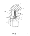
- FIG. 3 is a partial section view taken along lines A-A in FIG. 2 and generally illustrating a portion of second static component
- FIG. 4 is a perspective view of another embodiment of a brush seal assembly
- FIG. 5 is a side view of the assembly shown in FIG. 4 ;
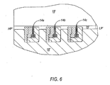
- FIG. 6 is a partial sectional view the assembly shown including a plurality of brush seals.
- FIG. 1 generally illustrates a perspective view of a brush seal assembly 10 according to an embodiment of the invention.
- the brush seal assembly 10 may be comprised of two or more segments that form a portion of an outer periphery of the assembly.
- the assembly 10 illustrated in FIG. 1 includes two separate segments - shown separated by separation lines 12a, 12b - each shown extending approximately 180°.
- FIG. 2 generally illustrates a front view of the assembly 10 shown in FIG. 1 .
- the assembly may be connected with, and in some cases may include, other second static components, such as various casings (e.g., item 18 in Fig. 3 ).
- second static components such as various casings (e.g., item 18 in Fig. 3 ).
- the assembly 10 When connected with a second component, the assembly 10 may, for example and without limitation, be rotated or spun into an engaged position. Alternatively, portions of the assembly may be configured to separate and then to overlap in their operational configuration to provide for improved assembly.
- the brush seal assembly 10 may include a brush seal (which may also be referred to as a "brush seal insert") 14 that provides a functional or operative seal between a first static component 16 and a second static component 18, which may be associated with or connected to elements of a housing 18.
- a brush seal which may also be referred to as a "brush seal insert”
- the term "static” is meant to generally pertain to substantially stationary, non-rotating components. However, it is noted that with “static” components there may still be some measure of movement, for example, expansions and/or contractions in response to changes in thermal conditions.
- first static component 16 includes a groove or receiving portion 20 for receiving a portion of the brush seal 14.
- Groove or receiving portion 20 may, for example, have a length taken along a longitudinal direction of the assembly of at least 0.050 inches.
- the first static component 16 may have a length taken along a longitudinal direction of the assembly of .510 inches ⁇ .002 inches.
- Brush seal 14 may include a segment or ring 22 that is retained within a portion of the groove or receiving portion 20 of the first static component 16.
- Brush seal 14 further includes a plurality of bristles (generally represented as 24) that extend in a radially outward direction from the first static component.
- An outer portion of the bristles 24 form a seal against second static component 18.
- Bristles 24 may, for example, be comprised of a bronze alloy, a ceramic material, a stainless steel alloy, a cobalt-based alloy, or a nickel-based alloy.
- bristles 24 may be interference-fit within the groove or receiving portion 20 of first static component 16 and, for some applications, may not include a weld bead.
- First and second static components 16,18 can be configured to form a flow path (generally identified as 26) from a first (e.g. high-pressure) pressure cavity HP to a second (e.g., low-pressure) pressure cavity LP.
- Brush seal 14 may be interposed along the flow path 26 formed between the first and second static components 16,18, functionally separating and limiting the amount of flow between first and second pressure cavities HP,LP.
- the seal 14 may be provided such that only a portion of the bristles 24 are configured to sealingly engage or contact a portion of second static component.
- the brush seal does not include a static seal (e.g., a labyrinth seal) with respect to the second static component. That is, conventional labyrinth-type seals generally require at least one labyrinth tooth for use as a backing. The present invention does not require such a tooth or backing.
- brush seal ring or segment 22 may include one or more side plates or rails (e.g., 28, 30) adjacent to the bristles and received within a portion of the receiving portion 20 of first static component 16.
- the one or more brush seal side plates or rails may, without limitation, be comprised of stainless steel or a nickel-based alloy.
- all or a portion of the one or more side plates or rails 28,30 may be flexible and/or linear.
- the side plates or rails may be configured to be generally annular and, if desired, may comprise a rigid ring.
- first and second static components 16,18 may be comprised of different materials that have different rates of thermal expansion. Differing rates of thermal expansion of first and second static components 16,18 in proximity to the brush seal 14 can provide a gap between surfaces of first and second static components under one or more operational conditions. For many applications, a large difference in thermal expansion may be anticipated. Many conventional static brush seals may only permit a radial expansion of 0.050 inch. As discussed further herein, embodiments of the present invention may permit radial movement up to 1 ⁇ 2 inch or more.
- the assembly may also take into account the radial movement of the bristles 28.
- the bristles are generally in operational contact with the second static component 18, and the gap between the first and second static components 16,18 becomes reduced, in an embodiment the bristles are provided with some measure of responsive radial movement.
- the brush seal 14, and consequently the associated bristles may have some radial "play" within groove or receiving portion 20. In some instances, such range of movement can relieve or reduce contact stresses between the bristles 24 and the second static component 18.
- bristles 24 have a range, for example, of from 0.050 inches to 0.060 inches. In another embodiment, bristles 24 may have a radial range of movement of at least 0.060 inches. In yet other embodiments, bristles 24 may have a radial range of movement of 0.20 inches or more. Moreover, for some applications, it may be desirable to provide bristles 24 to form a bristle pack having a density that is sufficient to prevent splaying apart circumferentially when the bristles extend radially outwardly in a contact configuration. That is, the assembly can be provided to maintain substantially constant interference and maintain pack density.
- the bristles have a uniform pack density throughout their extent from the first static component 16 to an outer sealing end that sealingly engaging a second static component 18.
- the brush seal 14 may include a side plate or rail with a moment of inertia of 5 x 10 -5 inches 4 or less.
- bristles 24 may be oriented at an angle of 20 to 90 degrees tangent to a sealing surface of the second static component 18.
- FIGS. 4-6 generally represent additional embodiments of the invention with a plurality of brush seals. More specifically, FIG. 4 illustrates a perspective view of an embodiment of an assembly 10' shown with three outer diameter brush seals 14a,14b,14c, each brush seal extending circumferentially, or substantially circumferentially, around the outer perimeter of the assembly.
- FIG. 5 is a side view of the assembly shown in FIG. 4 .
- FIG. 6 is partial sectional view of the assembly 10' similar to the view shown in FIG. 3 .
- one or more brush seals 14a,14b,14c may be included with the assembly 10'.
- brush seals 14a,14b,14c may be interposed along a flow path 26' formed between the first and second static components 16',18', functionally separating and limiting the amount of flow between first and second pressure cavities HP',LP'.
Landscapes
- Engineering & Computer Science (AREA)
- General Engineering & Computer Science (AREA)
- Mechanical Engineering (AREA)
- Sealing Devices (AREA)
- Turbine Rotor Nozzle Sealing (AREA)
Abstract
Description
- The present invention relates to static outside diameter sealing brush seals.
- Brush seals provide a technology for sealing high pressure areas from low pressure areas, for example, areas associated with gas turbine engines. Typically, brush seals inhibit the flow of a gas in a stream along a shaft.
- An outside diameter brush seal assembly is disclosed. The brush seal assembly includes a first static component, a second static component, and a brush seal. The first and second static components may be configured to form a flow path from a first pressure cavity to a second pressure cavity. The brush seal includes a plurality of bristles that extend in a radially outward direction from the first static component to form a seal against the second static component.
- Embodiments of the invention will now be described, by way of example, with reference to the accompanying drawings, wherein:
-
FIG. 1 is a perspective view of an embodiment of a brush seal assembly; -
FIG. 2 is a front view of the assembly illustrated inFIG. 1 ; -
FIG. 3 is a partial section view taken along lines A-A inFIG. 2 and generally illustrating a portion of second static component; -
FIG. 4 is a perspective view of another embodiment of a brush seal assembly; -
FIG. 5 is a side view of the assembly shown inFIG. 4 ; and -
FIG. 6 is a partial sectional view the assembly shown including a plurality of brush seals. - Reference will now be made in detail to embodiments of the present invention, examples of which are described herein and illustrated in the accompanying drawings. While the invention will be described in conjunction with embodiments, it will be understood that they are not intended to limit the invention to these embodiments. On the contrary, the invention is intended to cover alternatives, modifications and equivalents, which may be included within the spirit and scope of the invention as defined by the appended claims.
-
FIG. 1 generally illustrates a perspective view of abrush seal assembly 10 according to an embodiment of the invention. Thebrush seal assembly 10 may be comprised of two or more segments that form a portion of an outer periphery of the assembly. For example, without limitation, theassembly 10 illustrated inFIG. 1 includes two separate segments - shown separated byseparation lines FIG. 2 generally illustrates a front view of theassembly 10 shown inFIG. 1 . - The assembly may be connected with, and in some cases may include, other second static components, such as various casings (e.g.,
item 18 inFig. 3 ). When connected with a second component, theassembly 10 may, for example and without limitation, be rotated or spun into an engaged position. Alternatively, portions of the assembly may be configured to separate and then to overlap in their operational configuration to provide for improved assembly. - As illustrated in
FIG. 3 , thebrush seal assembly 10 may include a brush seal (which may also be referred to as a "brush seal insert") 14 that provides a functional or operative seal between a firststatic component 16 and a secondstatic component 18, which may be associated with or connected to elements of ahousing 18. As used herein, the term "static" is meant to generally pertain to substantially stationary, non-rotating components. However, it is noted that with "static" components there may still be some measure of movement, for example, expansions and/or contractions in response to changes in thermal conditions. - In an embodiment, first
static component 16 includes a groove or receivingportion 20 for receiving a portion of thebrush seal 14. Groove or receivingportion 20 may, for example, have a length taken along a longitudinal direction of the assembly of at least 0.050 inches. In an embodiment, the firststatic component 16 may have a length taken along a longitudinal direction of the assembly of .510 inches ± .002 inches. -
Brush seal 14 may include a segment orring 22 that is retained within a portion of the groove or receivingportion 20 of the firststatic component 16.Brush seal 14 further includes a plurality of bristles (generally represented as 24) that extend in a radially outward direction from the first static component. An outer portion of thebristles 24 form a seal against secondstatic component 18.Bristles 24 may, for example, be comprised of a bronze alloy, a ceramic material, a stainless steel alloy, a cobalt-based alloy, or a nickel-based alloy. In an embodiment,bristles 24 may be interference-fit within the groove or receivingportion 20 of firststatic component 16 and, for some applications, may not include a weld bead. - First and second
static components Brush seal 14 may be interposed along theflow path 26 formed between the first and secondstatic components seal 14 may be provided such that only a portion of thebristles 24 are configured to sealingly engage or contact a portion of second static component. Further in an embodiment, the brush seal does not include a static seal (e.g., a labyrinth seal) with respect to the second static component. That is, conventional labyrinth-type seals generally require at least one labyrinth tooth for use as a backing. The present invention does not require such a tooth or backing. - In an embodiment, brush seal ring or
segment 22 may include one or more side plates or rails (e.g., 28, 30) adjacent to the bristles and received within a portion of thereceiving portion 20 of firststatic component 16. The one or more brush seal side plates or rails may, without limitation, be comprised of stainless steel or a nickel-based alloy. For some embodiments, all or a portion of the one or more side plates orrails - For some embodiments, first and second
static components static components brush seal 14 can provide a gap between surfaces of first and second static components under one or more operational conditions. For many applications, a large difference in thermal expansion may be anticipated. Many conventional static brush seals may only permit a radial expansion of 0.050 inch. As discussed further herein, embodiments of the present invention may permit radial movement up to ½ inch or more. - Because the gap between the surfaces of the first and second
static components bristles 28, with the selection of materials based, for instance, on desired results (e.g., gap control) in connection with anticipated operating conditions. For many applications, the assembly may also take into account the radial movement of thebristles 28. For example, without limitation, if the bristles are generally in operational contact with the secondstatic component 18, and the gap between the first and secondstatic components FIG. 3 , thebrush seal 14, and consequently the associated bristles may have some radial "play" within groove or receivingportion 20. In some instances, such range of movement can relieve or reduce contact stresses between thebristles 24 and the secondstatic component 18. - For some embodiments,
bristles 24 have a range, for example, of from 0.050 inches to 0.060 inches. In another embodiment,bristles 24 may have a radial range of movement of at least 0.060 inches. In yet other embodiments,bristles 24 may have a radial range of movement of 0.20 inches or more. Moreover, for some applications, it may be desirable to providebristles 24 to form a bristle pack having a density that is sufficient to prevent splaying apart circumferentially when the bristles extend radially outwardly in a contact configuration. That is, the assembly can be provided to maintain substantially constant interference and maintain pack density. In some embodiments, the bristles have a uniform pack density throughout their extent from the firststatic component 16 to an outer sealing end that sealingly engaging a secondstatic component 18. If desired, particularly for ensuring that the brush seal remains flexible and does not need to be too large, thebrush seal 14 may include a side plate or rail with a moment of inertia of 5 x 10⁻⁵ inches4 or less. Additionally, in an embodiment, bristles 24 may be oriented at an angle of 20 to 90 degrees tangent to a sealing surface of the secondstatic component 18. - The invention is not, however, limited to brush seal assemblies having a single brush seal.
FIGS. 4-6 generally represent additional embodiments of the invention with a plurality of brush seals. More specifically,FIG. 4 illustrates a perspective view of an embodiment of an assembly 10' shown with three outerdiameter brush seals FIG. 5 is a side view of the assembly shown inFIG. 4 . -
FIG. 6 is partial sectional view of the assembly 10' similar to the view shown inFIG. 3 . As generally shown, one ormore brush seals brush seals static components 16',18', functionally separating and limiting the amount of flow between first and second pressure cavities HP',LP'. - The foregoing descriptions of specific embodiments of the present invention have been presented for purposes of illustration and description. They are not intended to be exhaustive or to limit the invention to the precise forms disclosed, and various modifications and variations are possible in light of the above teaching. The embodiments were chosen and described in order to explain the principles of the invention and its practical application, to thereby enable others skilled in the art to utilize the invention and various embodiments with various modifications as are suited to the particular use contemplated. It is intended that the scope of the invention be defined by the claims appended hereto and their equivalents.
Claims (18)
- An outside diameter brush seal assembly (10), comprising:a first static component (16) including a groove or receiving portion (20);a second static component (18), the first and second static components (16, 18) configured to form a flow path (26) from a first pressure cavity (HP) to a second pressure cavity (LP); anda flexible brush seal (14) including a segment or ring (22) retained within a portion of the groove or receiving portion (20) of the first static component (16), the brush seal (14) further including a plurality of bristles (24) that extend in a radially outward direction from the first static component (16) to form a brush seal (14) against the second static component (18);wherein the brush seal (14) is interposed along said flow path (26) between said first and second pressure cavities (HP, LP), and only the bristles (24) are configured to sealingly engage or contact a portion of the second static component (18).
- The brush seal assembly (10) of claim 1, wherein the brush seal (14) is devoid of a static seal with respect to the second static component (18).
- The brush seal assembly (10) of claim 1, wherein the brush seal (14) assembly is devoid of a labyrinth seal.
- The brush seal assembly (10) of claim 1, wherein the brush seal (14) limits the amount of flow between said first and second pressure cavities (HP, LP).
- The brush seal assembly (10) of claim 1, wherein the brush seal ring or segment (22) includes one or more side plates or rails (28, 30) adjacent to the bristles (24) and received within a portion of the receiving portion (20) of the first static component (16).
- The brush seal assembly (10) of claim 5, wherein the one or more side plates or rails (28, 30) are flexible.
- The brush seal assembly (10) of claim 5, wherein the side plates or rails (28, 30) are annular.
- The brush seal assembly (10) of claim 5, wherein the side plates or rails (28, 30) comprise a rigid ring.
- The brush seal assembly (10) of claim 5, wherein the side plates or rails (28, 30) are linear.
- The brush seal assembly (10) of claim 5, wherein the side plate or rail (28, 30) has a moment of inertia of 5 x 10⁻⁵ inches4 or less.
- The brush seal assembly (10) of claim 1, wherein the first and second static components (16, 18) are comprised of different materials and have different rates of thermal expansion.
- The brush seal assembly (10) of claim 1, wherein the bristles (24) have a radial range of movement of at least 0.060 inches.
- The brush seal assembly (10) of claim 1, wherein the bristles (24) are oriented at an angle of 30 to 90 degrees tangent to a sealing surface of the second static component (18).
- The brush seal assembly (10) of claim 1, wherein the bristles (24) are interference-fit within the groove or receiving portion (20) of the first static component (16).
- An outside diameter brush seal assembly (10'), comprising:a first static component (16') including a groove or receiving portion (20');a second static component (18'), the first and second static components (16', 18') configured to form a flow path (26') from a first pressure cavity (HP')to a second pressure cavity (LP'); anda plurality of flexible brush seals (14a, 14b, 14c), each brush seal including a segment or ring (22') retained within a portion of the groove or receiving portion (20') of the first static component (16'), the brush seal (14a, 14b, 14c) further including a plurality of bristles 24') that extend in a radially outward direction from the first static component (16')to form a brush seal against the second static component (18');wherein the plurality of brush seals (14a, 14b, 14c) are interposed along said flow path (26') between said first and second pressure cavities (HP', LP'), and only the bristles (24') are configured to sealingly engage or contact a portion of the second static component (18').
- The assembly (10') of claim 15, wherein the plurality of brush seals (14a, 14b, 14c) are devoid of a static seal.
- The assembly (10') of claim 15, wherein the brush seals (14a, 14b, 14c) include one or more side plates or rails (28', 30') adjacent to the bristles (24') and received within a portion of the receiving portion (20')of the first static component (16').
- The brush seal assembly (10') of claim 15, wherein the first and second static components (16', 18') have different rates of thermal expansion.
Applications Claiming Priority (1)
| Application Number | Priority Date | Filing Date | Title |
|---|---|---|---|
| US11/754,557 US20080296846A1 (en) | 2007-05-29 | 2007-05-29 | Static outside diameter brush seal assembly |
Publications (1)
| Publication Number | Publication Date |
|---|---|
| EP1998085A1 true EP1998085A1 (en) | 2008-12-03 |
Family
ID=39740053
Family Applications (1)
| Application Number | Title | Priority Date | Filing Date |
|---|---|---|---|
| EP08009770A Withdrawn EP1998085A1 (en) | 2007-05-29 | 2008-05-29 | Static outside diameter brush seal assembly |
Country Status (2)
| Country | Link |
|---|---|
| US (1) | US20080296846A1 (en) |
| EP (1) | EP1998085A1 (en) |
Cited By (3)
| Publication number | Priority date | Publication date | Assignee | Title |
|---|---|---|---|---|
| CN102913289A (en) * | 2011-08-03 | 2013-02-06 | 通用电气公司 | Outward bristle brush seal design for gas turbine application |
| EP2738358A1 (en) * | 2012-11-29 | 2014-06-04 | General Electric Company | Turbomachine component including a seal member |
| FR3011585A1 (en) * | 2013-10-09 | 2015-04-10 | Snecma | AIRCRAFT TURBOMACHINE ASSEMBLY COMPRISING A FREESTRATED AXIAL HOLDING RING OF A BRUSH JOINT |
Families Citing this family (10)
| Publication number | Priority date | Publication date | Assignee | Title |
|---|---|---|---|---|
| USD633991S1 (en) * | 2008-11-26 | 2011-03-08 | Nippon Valqua Industries, Ltd. | Gate valve seal |
| US8505923B2 (en) * | 2009-08-31 | 2013-08-13 | Sealeze, A Unit of Jason, Inc. | Brush seal with stress and deflection accommodating membrane |
| US8534673B2 (en) * | 2010-08-20 | 2013-09-17 | Mitsubishi Power Systems Americas, Inc. | Inter stage seal housing having a replaceable wear strip |
| US8845283B2 (en) * | 2010-11-29 | 2014-09-30 | General Electric Company | Compressor blade with flexible tip elements and process therefor |
| US20130256992A1 (en) * | 2012-03-27 | 2013-10-03 | General Electric Company | Brush seal system with elliptical clearance |
| CN106164547B (en) * | 2013-11-13 | 2018-06-22 | 福斯特惠勒(美国)公司 | Method and system for furnace sealing |
| US9587505B2 (en) | 2013-12-05 | 2017-03-07 | General Electric Company | L brush seal for turbomachinery application |
| US9322287B2 (en) | 2014-06-03 | 2016-04-26 | General Electric Company | Brush seal for turbine |
| US10962117B2 (en) * | 2017-12-18 | 2021-03-30 | Raytheon Technologies Corporation | Brush seal with spring-loaded backing plate |
| CN110657123B (en) * | 2018-06-28 | 2024-03-26 | 丹佛斯公司 | Sealing device for refrigerant compressor |
Citations (3)
| Publication number | Priority date | Publication date | Assignee | Title |
|---|---|---|---|---|
| FR2252516A1 (en) * | 1973-11-23 | 1975-06-20 | Rolls Royce | |
| US5265412A (en) * | 1992-07-28 | 1993-11-30 | General Electric Company | Self-accommodating brush seal for gas turbine combustor |
| EP1517006A1 (en) * | 2003-09-19 | 2005-03-23 | Snecma Moteurs | Gas turbine brush seal arrangement for cabin air supply |
Family Cites Families (13)
| Publication number | Priority date | Publication date | Assignee | Title |
|---|---|---|---|---|
| US4595207A (en) * | 1985-07-09 | 1986-06-17 | Mtu Motoren-Und Turbinen-Union Munchen Gmbh | Brush seal labyrinth sealing means between two machine parts |
| GB9020317D0 (en) * | 1990-09-18 | 1990-10-31 | Cross Mfg Co | Sealing devices |
| US5997004A (en) * | 1996-10-22 | 1999-12-07 | Flowserve Management Company | Hybrid floating brush seal |
| US6045134A (en) * | 1998-02-04 | 2000-04-04 | General Electric Co. | Combined labyrinth and brush seals for rotary machines |
| US6231047B1 (en) * | 1998-05-29 | 2001-05-15 | Eg&G Engineered Products | Brush seal |
| US6244599B1 (en) * | 1999-04-28 | 2001-06-12 | Flowserve Management Company | Floating brush seal |
| JP2002159343A (en) * | 2000-11-27 | 2002-06-04 | Eagle Engineering Aerospace Co Ltd | Brush type sealing device |
| JP4644378B2 (en) * | 2001-03-27 | 2011-03-02 | イーグル・エンジニアリング・エアロスペース株式会社 | Brush seal device |
| US20040094900A1 (en) * | 2002-11-15 | 2004-05-20 | Turnquist Norman Arnold | Brush seal for static turbine components |
| US6887038B2 (en) * | 2003-09-02 | 2005-05-03 | General Electric Company | Methods and apparatus to facilitate sealing between rotating turbine shafts |
| US7000923B2 (en) * | 2004-01-09 | 2006-02-21 | United Technologies Corporation | Quick build brush seals |
| DE102004038933A1 (en) * | 2004-08-11 | 2006-02-23 | Mtu Aero Engines Gmbh | sealing arrangement |
| US20060214378A1 (en) * | 2005-03-28 | 2006-09-28 | Xiaoqing Zheng | Brush seal with spiral groove back plate |
-
2007
- 2007-05-29 US US11/754,557 patent/US20080296846A1/en not_active Abandoned
-
2008
- 2008-05-29 EP EP08009770A patent/EP1998085A1/en not_active Withdrawn
Patent Citations (3)
| Publication number | Priority date | Publication date | Assignee | Title |
|---|---|---|---|---|
| FR2252516A1 (en) * | 1973-11-23 | 1975-06-20 | Rolls Royce | |
| US5265412A (en) * | 1992-07-28 | 1993-11-30 | General Electric Company | Self-accommodating brush seal for gas turbine combustor |
| EP1517006A1 (en) * | 2003-09-19 | 2005-03-23 | Snecma Moteurs | Gas turbine brush seal arrangement for cabin air supply |
Cited By (3)
| Publication number | Priority date | Publication date | Assignee | Title |
|---|---|---|---|---|
| CN102913289A (en) * | 2011-08-03 | 2013-02-06 | 通用电气公司 | Outward bristle brush seal design for gas turbine application |
| EP2738358A1 (en) * | 2012-11-29 | 2014-06-04 | General Electric Company | Turbomachine component including a seal member |
| FR3011585A1 (en) * | 2013-10-09 | 2015-04-10 | Snecma | AIRCRAFT TURBOMACHINE ASSEMBLY COMPRISING A FREESTRATED AXIAL HOLDING RING OF A BRUSH JOINT |
Also Published As
| Publication number | Publication date |
|---|---|
| US20080296846A1 (en) | 2008-12-04 |
Similar Documents
| Publication | Publication Date | Title |
|---|---|---|
| US20080296846A1 (en) | Static outside diameter brush seal assembly | |
| US7726660B2 (en) | Non-contacting seal for rotating surfaces | |
| US7631879B2 (en) | “L” butt gap seal between segments in seal assemblies | |
| US5135237A (en) | Brush seal with asymmetrical elements | |
| KR100577546B1 (en) | Seal between bucket and fixed shroud in turbine | |
| US6267381B1 (en) | Resilient strip seal arrangement | |
| US9587505B2 (en) | L brush seal for turbomachinery application | |
| EP0453315B1 (en) | Brush seals | |
| US8162324B2 (en) | Compliant plate seal with an annular ring for turbomachinery and methods of assembling the same | |
| US6131911A (en) | Brush seals and combined labyrinth and brush seals for rotary machines | |
| US5308088A (en) | Brush seal with flexible backing plate | |
| US8167313B2 (en) | Seal member, assembly and method | |
| US6431827B1 (en) | Bucket tip brush seals in steam turbines and methods of installation | |
| US8657298B2 (en) | Brush seal with backing plate tooth | |
| US6951339B2 (en) | Brush seal for static turbine components | |
| CN102913289A (en) | Outward bristle brush seal design for gas turbine application | |
| GB1598926A (en) | Brush seals | |
| US6808180B2 (en) | Brush seal | |
| EP2567072A2 (en) | Brush ring seal | |
| US20020050684A1 (en) | Brush seal device | |
| WO2008140451A1 (en) | Non-contacting seal for rotating surfaces | |
| US8459653B2 (en) | Seal assembly segment joints | |
| US20060228209A1 (en) | Abradable seal between a turbine rotor and a stationary component | |
| EP1559873A3 (en) | Sealing arrangement for turbomachinery | |
| US8490981B2 (en) | Brush seal |
Legal Events
| Date | Code | Title | Description |
|---|---|---|---|
| PUAI | Public reference made under article 153(3) epc to a published international application that has entered the european phase |
Free format text: ORIGINAL CODE: 0009012 |
|
| AK | Designated contracting states |
Kind code of ref document: A1 Designated state(s): AT BE BG CH CY CZ DE DK EE ES FI FR GB GR HR HU IE IS IT LI LT LU LV MC MT NL NO PL PT RO SE SI SK TR |
|
| AX | Request for extension of the european patent |
Extension state: AL BA MK RS |
|
| 17P | Request for examination filed |
Effective date: 20090113 |
|
| 17Q | First examination report despatched |
Effective date: 20090223 |
|
| AKX | Designation fees paid |
Designated state(s): DE FR GB SE |
|
| STAA | Information on the status of an ep patent application or granted ep patent |
Free format text: STATUS: THE APPLICATION IS DEEMED TO BE WITHDRAWN |
|
| 18D | Application deemed to be withdrawn |
Effective date: 20090707 |