EP1998029A2 - Nacelle for an aircraft engine with inlet flow control system and corresponding operating method - Google Patents
Nacelle for an aircraft engine with inlet flow control system and corresponding operating method Download PDFInfo
- Publication number
- EP1998029A2 EP1998029A2 EP08251765A EP08251765A EP1998029A2 EP 1998029 A2 EP1998029 A2 EP 1998029A2 EP 08251765 A EP08251765 A EP 08251765A EP 08251765 A EP08251765 A EP 08251765A EP 1998029 A2 EP1998029 A2 EP 1998029A2
- Authority
- EP
- European Patent Office
- Prior art keywords
- nacelle
- plenum
- air
- air flow
- recited
- Prior art date
- Legal status (The legal status is an assumption and is not a legal conclusion. Google has not performed a legal analysis and makes no representation as to the accuracy of the status listed.)
- Granted
Links
Images


Classifications
-
- F—MECHANICAL ENGINEERING; LIGHTING; HEATING; WEAPONS; BLASTING
- F02—COMBUSTION ENGINES; HOT-GAS OR COMBUSTION-PRODUCT ENGINE PLANTS
- F02C—GAS-TURBINE PLANTS; AIR INTAKES FOR JET-PROPULSION PLANTS; CONTROLLING FUEL SUPPLY IN AIR-BREATHING JET-PROPULSION PLANTS
- F02C7/00—Features, components parts, details or accessories, not provided for in, or of interest apart form groups F02C1/00 - F02C6/00; Air intakes for jet-propulsion plants
- F02C7/04—Air intakes for gas-turbine plants or jet-propulsion plants
- F02C7/045—Air intakes for gas-turbine plants or jet-propulsion plants having provisions for noise suppression
-
- B—PERFORMING OPERATIONS; TRANSPORTING
- B64—AIRCRAFT; AVIATION; COSMONAUTICS
- B64D—EQUIPMENT FOR FITTING IN OR TO AIRCRAFT; FLIGHT SUITS; PARACHUTES; ARRANGEMENT OR MOUNTING OF POWER PLANTS OR PROPULSION TRANSMISSIONS IN AIRCRAFT
- B64D33/00—Arrangement in aircraft of power plant parts or auxiliaries not otherwise provided for
- B64D33/02—Arrangement in aircraft of power plant parts or auxiliaries not otherwise provided for of combustion air intakes
-
- F—MECHANICAL ENGINEERING; LIGHTING; HEATING; WEAPONS; BLASTING
- F02—COMBUSTION ENGINES; HOT-GAS OR COMBUSTION-PRODUCT ENGINE PLANTS
- F02C—GAS-TURBINE PLANTS; AIR INTAKES FOR JET-PROPULSION PLANTS; CONTROLLING FUEL SUPPLY IN AIR-BREATHING JET-PROPULSION PLANTS
- F02C6/00—Plural gas-turbine plants; Combinations of gas-turbine plants with other apparatus; Adaptations of gas-turbine plants for special use
- F02C6/04—Gas-turbine plants providing heated or pressurised working fluid for other apparatus, e.g. without mechanical power output
- F02C6/06—Gas-turbine plants providing heated or pressurised working fluid for other apparatus, e.g. without mechanical power output providing compressed gas
- F02C6/08—Gas-turbine plants providing heated or pressurised working fluid for other apparatus, e.g. without mechanical power output providing compressed gas the gas being bled from the gas-turbine compressor
-
- F—MECHANICAL ENGINEERING; LIGHTING; HEATING; WEAPONS; BLASTING
- F02—COMBUSTION ENGINES; HOT-GAS OR COMBUSTION-PRODUCT ENGINE PLANTS
- F02K—JET-PROPULSION PLANTS
- F02K1/00—Plants characterised by the form or arrangement of the jet pipe or nozzle; Jet pipes or nozzles peculiar thereto
- F02K1/28—Plants characterised by the form or arrangement of the jet pipe or nozzle; Jet pipes or nozzles peculiar thereto using fluid jets to influence the jet flow
-
- F—MECHANICAL ENGINEERING; LIGHTING; HEATING; WEAPONS; BLASTING
- F02—COMBUSTION ENGINES; HOT-GAS OR COMBUSTION-PRODUCT ENGINE PLANTS
- F02K—JET-PROPULSION PLANTS
- F02K3/00—Plants including a gas turbine driving a compressor or a ducted fan
- F02K3/02—Plants including a gas turbine driving a compressor or a ducted fan in which part of the working fluid by-passes the turbine and combustion chamber
- F02K3/04—Plants including a gas turbine driving a compressor or a ducted fan in which part of the working fluid by-passes the turbine and combustion chamber the plant including ducted fans, i.e. fans with high volume, low pressure outputs, for augmenting the jet thrust, e.g. of double-flow type
- F02K3/06—Plants including a gas turbine driving a compressor or a ducted fan in which part of the working fluid by-passes the turbine and combustion chamber the plant including ducted fans, i.e. fans with high volume, low pressure outputs, for augmenting the jet thrust, e.g. of double-flow type with front fan
-
- B—PERFORMING OPERATIONS; TRANSPORTING
- B64—AIRCRAFT; AVIATION; COSMONAUTICS
- B64D—EQUIPMENT FOR FITTING IN OR TO AIRCRAFT; FLIGHT SUITS; PARACHUTES; ARRANGEMENT OR MOUNTING OF POWER PLANTS OR PROPULSION TRANSMISSIONS IN AIRCRAFT
- B64D33/00—Arrangement in aircraft of power plant parts or auxiliaries not otherwise provided for
- B64D33/02—Arrangement in aircraft of power plant parts or auxiliaries not otherwise provided for of combustion air intakes
- B64D2033/0226—Arrangement in aircraft of power plant parts or auxiliaries not otherwise provided for of combustion air intakes comprising boundary layer control means
Definitions
- This invention generally relates to a nacelle structure for a gas turbine engine.
- a nacelle defines an inlet for air flow into a gas turbine engine.
- air flow along the interior surface of the nacelle is turbulent resulting in a thin boundary layer.
- This turbulent airflow within this thin boundary layer into the gas turbine engine provides desired operating performance.
- local flow fields result in an increased boundary layer thickness that can separate from the interior surface of the nacelle. Separation of air flow from the interior surface of the nacelle is not desirable and can result in a reduction in engine operating performance.
- a disclosed example nacelle includes an inlet flow control system that injects air into the into a nacelle air intake opening to control intake air flow.
- An example nacelle assembly includes an outer surface, an inner surface and an air intake opening.
- An inlet duct is disposed within the nacelle aft of exit guide vanes for drawing air into a passage disposed within the nacelle. Air drawn from aft of the exit guide vanes is communicated through a plurality of passages to a plurality of outlets proximate the air intake opening of the nacelle. Air is communicated through the outlets into the air intake opening into the nacelle assembly.
- the additional air flow into the nacelle intake provides control of air flow to maintain the desired turbulent flow with a desired relatively thin boundary layer and prevent separation of airflow from the inner surface of the nacelle assembly.
- the example nacelle assembly improves and maintains air flow characteristics along the inner surface of the nacelle assembly in order to provide the desired operation of the gas turbine engine assembly.
- an example gas turbine engine assembly 10 is housed within a nacelle 12.
- the nacelle 12 includes an intake opening 16, a trailing edge 18, an inner surface 22, and an outer surface 20.
- Airflow schematically indicated at 14 is directed into the gas turbine engine assembly 10 through the intake opening 16 of the nacelle 12.
- incoming air into the nacelle 12 flows along the inner surface 22. This airflow condition is such that the air is uniformly directed into the fan blades 34 of the gas turbine engine 10.
- outlets 32 provide added airflow to the intake opening 16 that increases the airflow velocity.
- the increased velocity airflow reduces thickness of the boundary layer to substantially preventing separation of air flow from the inner surfaces of the nacelle 12. Separation from the inner surface of the nacelle 12 can result in undesirable intake air flow which can affect engine performance.
- the example nacelle assembly 12 includes an inlet flow control system that controls and adds inlet air flow into the nacelle assembly 12.
- the inlet flow control system includes the outlets 32 through which air is injected into the nacelle 12.
- the nacelle assembly 12 includes the inner surface 22 that is spaced radially inward from the outer surface 20.
- Inlet air 14 flows along the outer surface 20 and the inner surface 22.
- the inlet flow control system provides air from a position aft of an exit guide vane 42 to the intake opening 16.
- the example inlet flow control system includes an integrally formed inlet passage 24 that is disposed aft of the exit guide vane 42 of the intake fan 34.
- the inlets 24 feed a plurality of separate passages 26 that direct air to a plenum 30.
- the plenum 30 is disposed substantially adjacent to the intake opening 16 of the nacelle assembly 12.
- the plurality of outlets 32 are disposed in communication with the plenum 30 and supply air flow 36 proximate the intake opening 16.
- the example outlets 32 each include a flow control device that governs air flow out of the plenum 30.
- the flow control device comprises an orifice 44 sized to provide a desired air flow at a given pressure. Additionally, other flow control devices such as selectively controlled valves could also be utilized for controlling air flow from the plenum 30.
- the additional air flow 36 from the plenum 30 provides for conditioning of air that flows within the nacelle 12.
- the additional air flow 36 is directed across the outer surface 20 over the intake opening 16 and into the intake of the nacelle 12. This additional air flow 36 maintains desired air flow characteristics along the inner surface 22 of the nacelle 12.
- a control valve 28 is included in each of the plurality of passages 26 to control airflow to the outlets 32.
- the control valves 28 are closed such that the additional air flow 36 is not directed to the plenum 30 and outlets 32.
- the valves 28 can be opened to direct the desired air flow.
- the control valves 28 can be proportionally opened to tailor the amount of air flow 36 emitted from the outlets 32 according to current operational requirements.
- another example nacelle includes the inlet 32 disposed to inject air along the inner surface 22.
- the example plenum 31 is disposed to supply airflow to the inlets 30 disposed near the intake opening 16 that are defined within the inner surface 22.
- airflow 36 from the array of openings 32 arranged along the inner surface 22 adds air directly into the inlet of the nacelle 12.
- the inlet flow control system is schematically shown and includes the plenum 30 disposed along a full circumference of the nacelle 12.
- the plenum 30 provides air flow through the outlets 32 that in turn provide additional air flow locally to improve and control inlet air flow.
- the example passages 26 are separate from each other to provide the desired air flow from each corresponding inlet 24 to the plenum 30.
- Each of the passages 26 includes a separate and independently actuateable control valve 28.
- the separate control valves 28 can be selectively opened and closed to provide a desired air flow and pressure to the plenum 30. Further, a combination of the plurality of control valves 28 can be partially opened or closed in order to meter air flow as desired to the plenum 30.
- Air within the plenum 30 is directed out through the plurality of outlets 32 as desired.
- the pressure and air flow within the plenum 30 governs the amount of air flow emitted through the outlets 32, and the control valves 28 control that air flow.
- the valves 28 remain closed and the pressure within the plenum 30 will match that of the ambient environment.
- the control valves 28 are opened to tailor pressure within the plenum 30 as required to provide the desired air flow through the plurality of outlets 32.
- Pressure within the plenum 30 governs air flow 36 out the outlets 32, across the intake opening 16 and into the nacelle 12.
- another example plenum 30 supplies air to outlets 32 disposed along less then the full circumference of the nacelle 12 to tailor injection of air along those portions of the inner surface 22.
- the example outlets 32 are disposed within an arc of 270° about the inner surface 22 to inject air along the lower portion of the nacelle 12.
- other arc angles are within the contemplation of this system to tailor injection air to desired operations. This provides the increased air in targeted areas that are most susceptible to increased boundary layer and separation.
- the targeted flow of air through the outlets provides efficient use of the additional air flow drawn from inlets 24. '
- the inlet flow control system of this invention provides additional air to maintain the desired air flow properties and stability along the inner surface of the nacelle 12.
Landscapes
- Engineering & Computer Science (AREA)
- Chemical & Material Sciences (AREA)
- Combustion & Propulsion (AREA)
- Mechanical Engineering (AREA)
- General Engineering & Computer Science (AREA)
- Aviation & Aerospace Engineering (AREA)
- Structures Of Non-Positive Displacement Pumps (AREA)
- Control Of Turbines (AREA)
Abstract
Description
- This invention generally relates to a nacelle structure for a gas turbine engine.
- A nacelle defines an inlet for air flow into a gas turbine engine. During most operating conditions air flow along the interior surface of the nacelle is turbulent resulting in a thin boundary layer. This turbulent airflow within this thin boundary layer into the gas turbine engine provides desired operating performance. In some operating conditions, such as during low speed, high power operation, local flow fields result in an increased boundary layer thickness that can separate from the interior surface of the nacelle. Separation of air flow from the interior surface of the nacelle is not desirable and can result in a reduction in engine operating performance.
- Accordingly, it is desirable to design and develop a nacelle with features to create and maintain desired air flow characteristics through the nacelle.
- A disclosed example nacelle includes an inlet flow control system that injects air into the into a nacelle air intake opening to control intake air flow.
- An example nacelle assembly includes an outer surface, an inner surface and an air intake opening. An inlet duct is disposed within the nacelle aft of exit guide vanes for drawing air into a passage disposed within the nacelle. Air drawn from aft of the exit guide vanes is communicated through a plurality of passages to a plurality of outlets proximate the air intake opening of the nacelle. Air is communicated through the outlets into the air intake opening into the nacelle assembly. The additional air flow into the nacelle intake provides control of air flow to maintain the desired turbulent flow with a desired relatively thin boundary layer and prevent separation of airflow from the inner surface of the nacelle assembly.
- Accordingly, the example nacelle assembly improves and maintains air flow characteristics along the inner surface of the nacelle assembly in order to provide the desired operation of the gas turbine engine assembly.
- These and other features of the present invention can be best understood from the following specification and drawings, the following of which is a brief description.
-
-
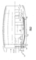
Figure 1 is a perspective view of a gas turbine engine assembly housed within a nacelle. -
Figure 2 is a cut away view of the example nacelle assembly including the example inlet control system. -
Figure 3 is a cut away view of another example nacelle assembly including another example inlet control system. -
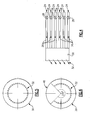
Figure 4 is a schematic representation of the example inlet control assembly. -
Figure 5 is a front schematic representation of the plenum for the example air inlet control assembly. -
Figure 6 is another front schematic representation of the plenum for the example air inlet control assembly. - Referring to
Figure 1 , an example gasturbine engine assembly 10 is housed within anacelle 12. Thenacelle 12 includes anintake opening 16, atrailing edge 18, aninner surface 22, and anouter surface 20. Airflow schematically indicated at 14 is directed into the gasturbine engine assembly 10 through theintake opening 16 of thenacelle 12. During most operating conditions, incoming air into thenacelle 12 flows along theinner surface 22. This airflow condition is such that the air is uniformly directed into thefan blades 34 of thegas turbine engine 10. - However, during some operating conditions, such as when the aircraft is moving at a relatively slow speed and the engine is operating at a relatively high power output, more airflow than is capable of being efficiently provided is required. In such instances,
outlets 32 provide added airflow to theintake opening 16 that increases the airflow velocity. The increased velocity airflow reduces thickness of the boundary layer to substantially preventing separation of air flow from the inner surfaces of thenacelle 12. Separation from the inner surface of thenacelle 12 can result in undesirable intake air flow which can affect engine performance. - The
example nacelle assembly 12 includes an inlet flow control system that controls and adds inlet air flow into thenacelle assembly 12. The inlet flow control system includes theoutlets 32 through which air is injected into thenacelle 12. - Referring to
Figure 2 , thenacelle assembly 12 includes theinner surface 22 that is spaced radially inward from theouter surface 20.Inlet air 14 flows along theouter surface 20 and theinner surface 22. During operation where additional airflow is desired to stabilize air flow along theinner surface 22, the inlet flow control system provides air from a position aft of anexit guide vane 42 to theintake opening 16. - The example inlet flow control system includes an integrally formed
inlet passage 24 that is disposed aft of theexit guide vane 42 of theintake fan 34. Theinlets 24 feed a plurality ofseparate passages 26 that direct air to aplenum 30. Theplenum 30 is disposed substantially adjacent to the intake opening 16 of thenacelle assembly 12. The plurality ofoutlets 32 are disposed in communication with theplenum 30 and supplyair flow 36 proximate theintake opening 16. Theexample outlets 32 each include a flow control device that governs air flow out of theplenum 30. In the example, the flow control device comprises anorifice 44 sized to provide a desired air flow at a given pressure. Additionally, other flow control devices such as selectively controlled valves could also be utilized for controlling air flow from theplenum 30. - The
additional air flow 36 from theplenum 30 provides for conditioning of air that flows within thenacelle 12. Theadditional air flow 36 is directed across theouter surface 20 over the intake opening 16 and into the intake of thenacelle 12. Thisadditional air flow 36 maintains desired air flow characteristics along theinner surface 22 of thenacelle 12. - A
control valve 28 is included in each of the plurality ofpassages 26 to control airflow to theoutlets 32. In instances whereair flow 14 provides sufficient air to maintain the desired flow properties along theinner surface 22, thecontrol valves 28 are closed such that theadditional air flow 36 is not directed to theplenum 30 andoutlets 32. When additional air flow is required thevalves 28 can be opened to direct the desired air flow. Further, thecontrol valves 28 can be proportionally opened to tailor the amount ofair flow 36 emitted from theoutlets 32 according to current operational requirements. - Referring to
Figure 3 , another example nacelle includes theinlet 32 disposed to inject air along theinner surface 22. Theexample plenum 31 is disposed to supply airflow to theinlets 30 disposed near theintake opening 16 that are defined within theinner surface 22. In this example,airflow 36 from the array ofopenings 32 arranged along theinner surface 22 adds air directly into the inlet of thenacelle 12. - Referring to
Figures 4 and 5 , the inlet flow control system is schematically shown and includes theplenum 30 disposed along a full circumference of thenacelle 12. Theplenum 30 provides air flow through theoutlets 32 that in turn provide additional air flow locally to improve and control inlet air flow. - The
example passages 26 are separate from each other to provide the desired air flow from eachcorresponding inlet 24 to theplenum 30. Each of thepassages 26 includes a separate and independentlyactuateable control valve 28. Theseparate control valves 28 can be selectively opened and closed to provide a desired air flow and pressure to theplenum 30. Further, a combination of the plurality ofcontrol valves 28 can be partially opened or closed in order to meter air flow as desired to theplenum 30. - Air within the
plenum 30 is directed out through the plurality ofoutlets 32 as desired. The pressure and air flow within theplenum 30 governs the amount of air flow emitted through theoutlets 32, and thecontrol valves 28 control that air flow. During operation where no additional air flow is required, thevalves 28 remain closed and the pressure within theplenum 30 will match that of the ambient environment. During operation, when additional air flow into thenacelle 12 is required, thecontrol valves 28 are opened to tailor pressure within theplenum 30 as required to provide the desired air flow through the plurality ofoutlets 32. Pressure within theplenum 30 governsair flow 36 out theoutlets 32, across theintake opening 16 and into thenacelle 12. - Referring to
Figure 6 , anotherexample plenum 30 supplies air tooutlets 32 disposed along less then the full circumference of thenacelle 12 to tailor injection of air along those portions of theinner surface 22. Theexample outlets 32 are disposed within an arc of 270° about theinner surface 22 to inject air along the lower portion of thenacelle 12. As appreciated, other arc angles are within the contemplation of this system to tailor injection air to desired operations. This provides the increased air in targeted areas that are most susceptible to increased boundary layer and separation. The targeted flow of air through the outlets provides efficient use of the additional air flow drawn frominlets 24. ' - Accordingly, the inlet flow control system of this invention provides additional air to maintain the desired air flow properties and stability along the inner surface of the
nacelle 12. Although a preferred embodiment of this invention has been disclosed, a worker of ordinary skill in this art would recognize that certain modifications would come within the scope of this invention. For that reason, the following claims should be studied to determine the true scope and content of this invention.
Claims (17)
- An inlet flow control system for a nacelle (12) comprising:an air intake opening (16);an inlet (24) disposed in an aft portion of the nacelle (12) for drawing in airflow;a plenum (30;31) disposed adjacent said air intake opening (16) for receiving air flow from said inlet (24); andan outlet (32) for communicating air flow from said plenum (30;31) to said air intake opening (16) of the nacelle (12) for tailoring airflow within said nacelle (12) to current operating conditions.
- The system as recited in claim 1, wherein said plenum (30;31) comprises a cavity within the nacelle.
- The system as recited in claim 1 or 2, wherein said outlet (32) comprises a flow control device for governing air flow out onto the leading edge of the nacelle (12).
- The system as recited in any preceding claim, including a plurality of separate inlets (24) for drawing air into a corresponding plurality of passages (26), where each of the plurality of passages (26) are in communication with said plenum (30).
- The system as recited in claim 4, including a corresponding plurality of control valves (28) for governing air flow from each of said plurality of inlets (24) and said plenum (30).
- The system as recited in any preceding claim, wherein said outlet comprises a plurality of outlets (32) which are disposed about an entire circumference of the air intake opening (16).
- The system as recited in any of claims 1 to 5, wherein said outlet coprises a plurality of outlets (32) which are disposed about a partial portion of the air intake opening (16).
- The system as recited in any preceding claim, wherein said outlet (32) communicates air to an external surface (20) of said nacelle (12).
- The system as recited in any of claims 1 to 7, wherein said outlet (32) communicates air to an internal surface (22) of said nacelle (12).
- A nacelle assembly for a gas turbine engine comprising:an outer surface (20);an inner surface (22) defining an air flow path;an intake opening (16) disposed between said outer surface (20) and said inner surface (22);a plenum (30;31) disposed within said nacelle assembly;an outlet (32) in communication with said plenum (30;31) for directing air flow into said air intake opening (16) onto said inner surface (22) for controlling flow properties of intake air into said nacelle (12);an inlet (24) for supplying exhaust air flow to said plenum (30;31); anda control valve (28) for controlling air flow from said inlet (24) to said plenum (30;31).
- The assembly as recited in claim 10, wherein said plenum (30;31) comprises a cavity disposed about a circumference of said nacelle.
- The assembly as recited in claim 10 or 11, wherein said outlet (32) comprises a plurality of outlets (32) in said outer surface (20) that are disposed at least partially about a circumference of said nacelle (12), or a plurality of outlets (32) in said inner surface (22) that are disposed at least partially about a circumference of said nacelle (12).
- The assembly as recited in claim 10, 11 or 12, including a plurality of passages (26) between said inlet (24) and said plenum (30;31) and a corresponding plurality of control valves (28) for controlling air flow from said plurality of inlets (24) to said plenum (30;31).
- The assembly as recited in any of claims 10 to 13, wherein said inlet (24) is disposed aft of an exhaust guide vane (42) of the gas turbine engine.
- A method of controlling air flow through an intake of a nacelle assembly (12), said method comprising the steps of:a) drawing air from an aft portion of the nacelle assembly (12) through a plurality of separate passages (26);b) receiving air flow from the plurality of passages (26) into a cavity (30;31) near an intake opening (16) of the nacelle assembly; andc) injecting air into the intake opening (16) of the nacelle assembly for tailoring airflow along an inner surface (22) of the nacelle (12) near the leading edge that flows over the leading edge and into the nacelle assembly.
- The method as recited in claim 15 including the step of controlling the air flow through the passage (26) with a control valve (28).
- The method as recited in claim 16 including the step of selectively opening the control valve (28) to control a pressure within the cavity (30;31).
Applications Claiming Priority (1)
| Application Number | Priority Date | Filing Date | Title |
|---|---|---|---|
| US11/754,561 US7708230B2 (en) | 2007-05-29 | 2007-05-29 | Flow distribution system for inlet flow control |
Publications (3)
| Publication Number | Publication Date |
|---|---|
| EP1998029A2 true EP1998029A2 (en) | 2008-12-03 |
| EP1998029A3 EP1998029A3 (en) | 2011-09-07 |
| EP1998029B1 EP1998029B1 (en) | 2017-03-01 |
Family
ID=39714154
Family Applications (1)
| Application Number | Title | Priority Date | Filing Date |
|---|---|---|---|
| EP08251765.7A Active EP1998029B1 (en) | 2007-05-29 | 2008-05-21 | Inlet flow control system for a nacelle, corresponding nacelle assembly and method of controlling air flow |
Country Status (3)
| Country | Link |
|---|---|
| US (1) | US7708230B2 (en) |
| EP (1) | EP1998029B1 (en) |
| JP (1) | JP2008298066A (en) |
Cited By (3)
| Publication number | Priority date | Publication date | Assignee | Title |
|---|---|---|---|---|
| EP1998027A3 (en) * | 2007-05-29 | 2011-09-07 | United Technologies Corporation | Gas turbine engine comprising a nacelle compartment plenum for bleed air flow delivery system |
| EP3096023A1 (en) * | 2015-05-19 | 2016-11-23 | Rolls-Royce plc | Compressor tip injector |
| US10371059B2 (en) | 2014-12-11 | 2019-08-06 | Rolls-Royce Plc | Cabin blower system |
Families Citing this family (10)
| Publication number | Priority date | Publication date | Assignee | Title |
|---|---|---|---|---|
| FR2924408B1 (en) * | 2007-12-03 | 2010-05-07 | Airbus France | TURBOREACTOR NACELLE AND METHOD FOR CONTROLLING DECOLUTION IN A TURBOREACTEUR NACELLE |
| GB201121889D0 (en) * | 2011-12-20 | 2012-02-01 | Rolls Royce Plc | Active flow control intake for a gas turbine engine |
| WO2014185997A2 (en) | 2013-02-04 | 2014-11-20 | United Technologies Corporation | Rotary valve for bleed flow path |
| PL232261B1 (en) | 2015-11-02 | 2019-05-31 | Gen Electric | Method and the system for decreasing resonance in a chamber |
| DE102016112604A1 (en) * | 2016-07-08 | 2018-01-11 | Rolls-Royce Deutschland Ltd & Co Kg | Engine nacelle and method for influencing flows in an engine nacelle |
| US10605113B2 (en) * | 2017-06-16 | 2020-03-31 | The Boeing Company | Methods and apparatus for reducing flow distortion at engine fans of nacelles |
| US11046445B2 (en) | 2017-07-26 | 2021-06-29 | Raytheon Technologies Corporation | Nacelle |
| US10767596B2 (en) * | 2017-07-26 | 2020-09-08 | Raytheon Technologies Corporation | Nacelle |
| US11828237B2 (en) | 2020-04-28 | 2023-11-28 | General Electric Company | Methods and apparatus to control air flow separation of an engine |
| US11333079B2 (en) * | 2020-04-28 | 2022-05-17 | General Electric Company | Methods and apparatus to detect air flow separation of an engine |
Citations (5)
| Publication number | Priority date | Publication date | Assignee | Title |
|---|---|---|---|---|
| GB619390A (en) | 1946-12-06 | 1949-03-08 | Adrian Albert Lombard | Improvements in or relating to gas-turbine power-plant installations |
| US4154256A (en) | 1978-03-29 | 1979-05-15 | The United States Of America As Represented By The Administrator Of The National Aeronautics And Space Administration | Self stabilizing sonic inlet |
| EP0974515A2 (en) | 1998-07-20 | 2000-01-26 | Manuel Munoz Saiz | Aircraft airconditioning energy recovery device |
| EP1921291A2 (en) | 2006-11-10 | 2008-05-14 | United Technologies Corporation | Gas turbine engine providing simulated boundary layer thickness increase |
| EP1942259A2 (en) | 2006-12-28 | 2008-07-09 | General Electric Company | Operating line control of a compression system with flow recirculation |
Family Cites Families (23)
| Publication number | Priority date | Publication date | Assignee | Title |
|---|---|---|---|---|
| FR779655A (en) * | 1934-01-02 | 1935-04-10 | Process for transforming heat energy into kinetic or potential energy | |
| US3770228A (en) * | 1971-12-08 | 1973-11-06 | Lockheed Aircraft Corp | Air inlet flap |
| US3981466A (en) * | 1974-12-23 | 1976-09-21 | The Boeing Company | Integrated thermal anti-icing and environmental control system |
| US4658579A (en) * | 1983-07-14 | 1987-04-21 | United Technologies Corporation | Load sharing for engine nacelle |
| AU581684B2 (en) * | 1984-10-08 | 1989-03-02 | Short Brothers Plc | Duct for hot air |
| US4749151A (en) * | 1985-09-19 | 1988-06-07 | The Boeing Company | Apparatus for re-energizing boundary layer air |
| US4738416A (en) * | 1986-09-26 | 1988-04-19 | Quiet Nacelle Corporation | Nacelle anti-icing system |
| US4993663A (en) * | 1989-06-01 | 1991-02-19 | General Electric Company | Hybrid laminar flow nacelle |
| US5114100A (en) * | 1989-12-29 | 1992-05-19 | The Boeing Company | Anti-icing system for aircraft |
| US5114103A (en) * | 1990-08-27 | 1992-05-19 | General Electric Company | Aircraft engine electrically powered boundary layer bleed system |
| DE4134051C2 (en) * | 1991-10-15 | 1995-02-02 | Mtu Muenchen Gmbh | Turbine jet engine with fan |
| US5490644A (en) * | 1993-12-20 | 1996-02-13 | The Boeing Company | Ducted boundary layer diverter |
| US5447283A (en) * | 1994-02-02 | 1995-09-05 | Grumman Aerospace Corporation | Blown boundary layer control system for a jet aircraft |
| US5485975A (en) * | 1994-07-19 | 1996-01-23 | Northrop Grumman Corporation | Slotted cowl inlet lip for introducing high pressure air |
| US5593112A (en) * | 1994-12-06 | 1997-01-14 | United Technologies Corporation | Nacelle air pump for vector nozzles for aircraft |
| US6179251B1 (en) * | 1998-02-06 | 2001-01-30 | Northrop Grumman Corporation | Thin inlet lip design for low drag and reduced nacelle size |
| US6264137B1 (en) * | 2000-02-25 | 2001-07-24 | Honeywell International Inc. | Inlet vortex bustor and ice protector for auxiliary power units |
| US6438941B1 (en) * | 2001-04-26 | 2002-08-27 | General Electric Company | Bifurcated splitter for variable bleed flow |
| US6651929B2 (en) * | 2001-10-29 | 2003-11-25 | Pratt & Whitney Canada Corp. | Passive cooling system for auxiliary power unit installation |
| FR2831922B1 (en) * | 2001-11-02 | 2004-04-30 | Airbus France | AIR INTAKE FOR COMMERCIAL AIRCRAFT REACTION ENGINE NACELLE |
| US6634595B2 (en) * | 2002-01-11 | 2003-10-21 | The Boeing Company | Method and apparatus for controlling aircraft inlet air flow |
| US6851255B2 (en) * | 2002-12-18 | 2005-02-08 | Pratt & Whitney Canada Corp. | Normally open reverse flow flapper valve |
| US6945031B2 (en) * | 2003-02-21 | 2005-09-20 | The Nordam Group, Inc. | Recessed engine nacelle |
-
2007
- 2007-05-29 US US11/754,561 patent/US7708230B2/en not_active Expired - Fee Related
-
2008
- 2008-05-02 JP JP2008120089A patent/JP2008298066A/en active Pending
- 2008-05-21 EP EP08251765.7A patent/EP1998029B1/en active Active
Patent Citations (5)
| Publication number | Priority date | Publication date | Assignee | Title |
|---|---|---|---|---|
| GB619390A (en) | 1946-12-06 | 1949-03-08 | Adrian Albert Lombard | Improvements in or relating to gas-turbine power-plant installations |
| US4154256A (en) | 1978-03-29 | 1979-05-15 | The United States Of America As Represented By The Administrator Of The National Aeronautics And Space Administration | Self stabilizing sonic inlet |
| EP0974515A2 (en) | 1998-07-20 | 2000-01-26 | Manuel Munoz Saiz | Aircraft airconditioning energy recovery device |
| EP1921291A2 (en) | 2006-11-10 | 2008-05-14 | United Technologies Corporation | Gas turbine engine providing simulated boundary layer thickness increase |
| EP1942259A2 (en) | 2006-12-28 | 2008-07-09 | General Electric Company | Operating line control of a compression system with flow recirculation |
Cited By (5)
| Publication number | Priority date | Publication date | Assignee | Title |
|---|---|---|---|---|
| EP1998027A3 (en) * | 2007-05-29 | 2011-09-07 | United Technologies Corporation | Gas turbine engine comprising a nacelle compartment plenum for bleed air flow delivery system |
| US8657567B2 (en) | 2007-05-29 | 2014-02-25 | United Technologies Corporation | Nacelle compartment plenum for bleed air flow delivery system |
| US10371059B2 (en) | 2014-12-11 | 2019-08-06 | Rolls-Royce Plc | Cabin blower system |
| EP3096023A1 (en) * | 2015-05-19 | 2016-11-23 | Rolls-Royce plc | Compressor tip injector |
| US10145387B2 (en) | 2015-05-19 | 2018-12-04 | Rolls-Royce Plc | Compressor tip injector |
Also Published As
| Publication number | Publication date |
|---|---|
| EP1998029B1 (en) | 2017-03-01 |
| JP2008298066A (en) | 2008-12-11 |
| EP1998029A3 (en) | 2011-09-07 |
| US20080296440A1 (en) | 2008-12-04 |
| US7708230B2 (en) | 2010-05-04 |
Similar Documents
| Publication | Publication Date | Title |
|---|---|---|
| US7708230B2 (en) | Flow distribution system for inlet flow control | |
| US8192147B2 (en) | Nacelle assembly having inlet bleed | |
| JP5571285B2 (en) | Control line control of a compression system with flow recirculation. | |
| EP1998027B1 (en) | Gas turbine engine comprising a nacelle compartment plenum for bleed air flow delivery system | |
| US9316111B2 (en) | Active turbine tip clearance control system | |
| CN106828946B (en) | Method and device for modifying the air intake of an aircraft engine | |
| JP5121339B2 (en) | Bypass turbo machine that artificially changes the throat | |
| CN109083690B (en) | Turbine engine with variable effective throat | |
| US10995678B2 (en) | Gas turbine engine with diversion pathway and semi-dimensional mass flow control | |
| US10113486B2 (en) | Method and system for modulated turbine cooling | |
| US8336288B2 (en) | Gas-turbine engine in particular aircraft engine | |
| US8984891B2 (en) | Flade discharge in 2-D exhaust nozzle | |
| US7353647B2 (en) | Methods and apparatus for assembling gas turbine engines | |
| CN105408611A (en) | Secondary nozzle for jet engine | |
| EP2074318B1 (en) | Turbofan engine and method of changing an effective nozzle exit area of the same | |
| US20090008505A1 (en) | Aircraft with a fluid-duct-system | |
| US11248534B2 (en) | System and method for engine eductor powered by alternate managed air system | |
| EP3106628B1 (en) | Inverse modulation of secondary bleed | |
| US20100170221A1 (en) | Turbo fan engine |
Legal Events
| Date | Code | Title | Description |
|---|---|---|---|
| PUAI | Public reference made under article 153(3) epc to a published international application that has entered the european phase |
Free format text: ORIGINAL CODE: 0009012 |
|
| AK | Designated contracting states |
Kind code of ref document: A2 Designated state(s): AT BE BG CH CY CZ DE DK EE ES FI FR GB GR HR HU IE IS IT LI LT LU LV MC MT NL NO PL PT RO SE SI SK TR |
|
| AX | Request for extension of the european patent |
Extension state: AL BA MK RS |
|
| PUAL | Search report despatched |
Free format text: ORIGINAL CODE: 0009013 |
|
| AK | Designated contracting states |
Kind code of ref document: A3 Designated state(s): AT BE BG CH CY CZ DE DK EE ES FI FR GB GR HR HU IE IS IT LI LT LU LV MC MT NL NO PL PT RO SE SI SK TR |
|
| AX | Request for extension of the european patent |
Extension state: AL BA MK RS |
|
| RIC1 | Information provided on ipc code assigned before grant |
Ipc: F02K 3/06 20060101ALI20110802BHEP Ipc: F02C 7/045 20060101AFI20110802BHEP Ipc: F02C 6/08 20060101ALI20110802BHEP Ipc: B64D 33/02 20060101ALI20110802BHEP Ipc: F02K 1/28 20060101ALI20110802BHEP |
|
| 17P | Request for examination filed |
Effective date: 20120302 |
|
| AKX | Designation fees paid |
Designated state(s): DE GB |
|
| RAP1 | Party data changed (applicant data changed or rights of an application transferred) |
Owner name: UNITED TECHNOLOGIES CORPORATION |
|
| GRAP | Despatch of communication of intention to grant a patent |
Free format text: ORIGINAL CODE: EPIDOSNIGR1 |
|
| INTG | Intention to grant announced |
Effective date: 20161031 |
|
| GRAS | Grant fee paid |
Free format text: ORIGINAL CODE: EPIDOSNIGR3 |
|
| GRAA | (expected) grant |
Free format text: ORIGINAL CODE: 0009210 |
|
| AK | Designated contracting states |
Kind code of ref document: B1 Designated state(s): DE GB |
|
| REG | Reference to a national code |
Ref country code: GB Ref legal event code: FG4D |
|
| REG | Reference to a national code |
Ref country code: DE Ref legal event code: R096 Ref document number: 602008048915 Country of ref document: DE |
|
| REG | Reference to a national code |
Ref country code: DE Ref legal event code: R082 Ref document number: 602008048915 Country of ref document: DE Representative=s name: SCHMITT-NILSON SCHRAUD WAIBEL WOHLFROM PATENTA, DE |
|
| REG | Reference to a national code |
Ref country code: DE Ref legal event code: R097 Ref document number: 602008048915 Country of ref document: DE |
|
| PLBE | No opposition filed within time limit |
Free format text: ORIGINAL CODE: 0009261 |
|
| STAA | Information on the status of an ep patent application or granted ep patent |
Free format text: STATUS: NO OPPOSITION FILED WITHIN TIME LIMIT |
|
| 26N | No opposition filed |
Effective date: 20171204 |
|
| REG | Reference to a national code |
Ref country code: DE Ref legal event code: R081 Ref document number: 602008048915 Country of ref document: DE Owner name: RAYTHEON TECHNOLOGIES CORPORATION (N.D.GES.D.S, US Free format text: FORMER OWNER: UNITED TECHNOLOGIES CORPORATION, FARMINGTON, CONN., US Ref country code: DE Ref legal event code: R081 Ref document number: 602008048915 Country of ref document: DE Owner name: RTX CORPORATION (N.D.GES.D. STAATES DELAWARE),, US Free format text: FORMER OWNER: UNITED TECHNOLOGIES CORPORATION, FARMINGTON, CONN., US |
|
| P01 | Opt-out of the competence of the unified patent court (upc) registered |
Effective date: 20230519 |
|
| PGFP | Annual fee paid to national office [announced via postgrant information from national office to epo] |
Ref country code: DE Payment date: 20250423 Year of fee payment: 18 |
|
| PGFP | Annual fee paid to national office [announced via postgrant information from national office to epo] |
Ref country code: GB Payment date: 20250423 Year of fee payment: 18 |
|
| REG | Reference to a national code |
Ref country code: DE Ref legal event code: R081 Ref document number: 602008048915 Country of ref document: DE Owner name: RTX CORPORATION (N.D.GES.D. STAATES DELAWARE),, US Free format text: FORMER OWNER: RAYTHEON TECHNOLOGIES CORPORATION (N.D.GES.D.STAATES DELAWARE), ARLINGTON, VA, US |