EP1997550A1 - System for continuous removal of a specific gas from a flowing mixture of gases - Google Patents
System for continuous removal of a specific gas from a flowing mixture of gases Download PDFInfo
- Publication number
- EP1997550A1 EP1997550A1 EP08154626A EP08154626A EP1997550A1 EP 1997550 A1 EP1997550 A1 EP 1997550A1 EP 08154626 A EP08154626 A EP 08154626A EP 08154626 A EP08154626 A EP 08154626A EP 1997550 A1 EP1997550 A1 EP 1997550A1
- Authority
- EP
- European Patent Office
- Prior art keywords
- gas species
- medium
- entrance
- flowing
- accordance
- Prior art date
- Legal status (The legal status is an assumption and is not a legal conclusion. Google has not performed a legal analysis and makes no representation as to the accuracy of the status listed.)
- Granted
Links
Images


Classifications
-
- B—PERFORMING OPERATIONS; TRANSPORTING
- B01—PHYSICAL OR CHEMICAL PROCESSES OR APPARATUS IN GENERAL
- B01D—SEPARATION
- B01D53/00—Separation of gases or vapours; Recovering vapours of volatile solvents from gases; Chemical or biological purification of waste gases, e.g. engine exhaust gases, smoke, fumes, flue gases, aerosols
- B01D53/02—Separation of gases or vapours; Recovering vapours of volatile solvents from gases; Chemical or biological purification of waste gases, e.g. engine exhaust gases, smoke, fumes, flue gases, aerosols by adsorption, e.g. preparative gas chromatography
- B01D53/06—Separation of gases or vapours; Recovering vapours of volatile solvents from gases; Chemical or biological purification of waste gases, e.g. engine exhaust gases, smoke, fumes, flue gases, aerosols by adsorption, e.g. preparative gas chromatography with moving adsorbents, e.g. rotating beds
-
- B—PERFORMING OPERATIONS; TRANSPORTING
- B01—PHYSICAL OR CHEMICAL PROCESSES OR APPARATUS IN GENERAL
- B01D—SEPARATION
- B01D53/00—Separation of gases or vapours; Recovering vapours of volatile solvents from gases; Chemical or biological purification of waste gases, e.g. engine exhaust gases, smoke, fumes, flue gases, aerosols
- B01D53/02—Separation of gases or vapours; Recovering vapours of volatile solvents from gases; Chemical or biological purification of waste gases, e.g. engine exhaust gases, smoke, fumes, flue gases, aerosols by adsorption, e.g. preparative gas chromatography
- B01D53/04—Separation of gases or vapours; Recovering vapours of volatile solvents from gases; Chemical or biological purification of waste gases, e.g. engine exhaust gases, smoke, fumes, flue gases, aerosols by adsorption, e.g. preparative gas chromatography with stationary adsorbents
- B01D53/0407—Constructional details of adsorbing systems
- B01D53/0415—Beds in cartridges
-
- H—ELECTRICITY
- H01—ELECTRIC ELEMENTS
- H01M—PROCESSES OR MEANS, e.g. BATTERIES, FOR THE DIRECT CONVERSION OF CHEMICAL ENERGY INTO ELECTRICAL ENERGY
- H01M8/00—Fuel cells; Manufacture thereof
- H01M8/06—Combination of fuel cells with means for production of reactants or for treatment of residues
- H01M8/0662—Treatment of gaseous reactants or gaseous residues, e.g. cleaning
- H01M8/0675—Removal of sulfur
-
- B—PERFORMING OPERATIONS; TRANSPORTING
- B01—PHYSICAL OR CHEMICAL PROCESSES OR APPARATUS IN GENERAL
- B01D—SEPARATION
- B01D2251/00—Reactants
- B01D2251/10—Oxidants
- B01D2251/102—Oxygen
-
- B—PERFORMING OPERATIONS; TRANSPORTING
- B01—PHYSICAL OR CHEMICAL PROCESSES OR APPARATUS IN GENERAL
- B01D—SEPARATION
- B01D2251/00—Reactants
- B01D2251/20—Reductants
- B01D2251/202—Hydrogen
-
- B—PERFORMING OPERATIONS; TRANSPORTING
- B01—PHYSICAL OR CHEMICAL PROCESSES OR APPARATUS IN GENERAL
- B01D—SEPARATION
- B01D2253/00—Adsorbents used in seperation treatment of gases and vapours
- B01D2253/10—Inorganic adsorbents
-
- B—PERFORMING OPERATIONS; TRANSPORTING
- B01—PHYSICAL OR CHEMICAL PROCESSES OR APPARATUS IN GENERAL
- B01D—SEPARATION
- B01D2253/00—Adsorbents used in seperation treatment of gases and vapours
- B01D2253/30—Physical properties of adsorbents
- B01D2253/34—Specific shapes
- B01D2253/342—Monoliths
- B01D2253/3425—Honeycomb shape
-
- B—PERFORMING OPERATIONS; TRANSPORTING
- B01—PHYSICAL OR CHEMICAL PROCESSES OR APPARATUS IN GENERAL
- B01D—SEPARATION
- B01D2255/00—Catalysts
- B01D2255/20—Metals or compounds thereof
- B01D2255/206—Rare earth metals
-
- B—PERFORMING OPERATIONS; TRANSPORTING
- B01—PHYSICAL OR CHEMICAL PROCESSES OR APPARATUS IN GENERAL
- B01D—SEPARATION
- B01D2255/00—Catalysts
- B01D2255/20—Metals or compounds thereof
- B01D2255/207—Transition metals
- B01D2255/20753—Nickel
-
- B—PERFORMING OPERATIONS; TRANSPORTING
- B01—PHYSICAL OR CHEMICAL PROCESSES OR APPARATUS IN GENERAL
- B01D—SEPARATION
- B01D2256/00—Main component in the product gas stream after treatment
- B01D2256/24—Hydrocarbons
-
- B—PERFORMING OPERATIONS; TRANSPORTING
- B01—PHYSICAL OR CHEMICAL PROCESSES OR APPARATUS IN GENERAL
- B01D—SEPARATION
- B01D2257/00—Components to be removed
- B01D2257/30—Sulfur compounds
- B01D2257/304—Hydrogen sulfide
-
- B—PERFORMING OPERATIONS; TRANSPORTING
- B01—PHYSICAL OR CHEMICAL PROCESSES OR APPARATUS IN GENERAL
- B01D—SEPARATION
- B01D2259/00—Type of treatment
- B01D2259/40—Further details for adsorption processes and devices
- B01D2259/40083—Regeneration of adsorbents in processes other than pressure or temperature swing adsorption
- B01D2259/40086—Regeneration of adsorbents in processes other than pressure or temperature swing adsorption by using a purge gas
-
- H—ELECTRICITY
- H01—ELECTRIC ELEMENTS
- H01M—PROCESSES OR MEANS, e.g. BATTERIES, FOR THE DIRECT CONVERSION OF CHEMICAL ENERGY INTO ELECTRICAL ENERGY
- H01M8/00—Fuel cells; Manufacture thereof
- H01M8/10—Fuel cells with solid electrolytes
- H01M8/12—Fuel cells with solid electrolytes operating at high temperature, e.g. with stabilised ZrO2 electrolyte
- H01M2008/1293—Fuel cells with solid oxide electrolytes
-
- Y—GENERAL TAGGING OF NEW TECHNOLOGICAL DEVELOPMENTS; GENERAL TAGGING OF CROSS-SECTIONAL TECHNOLOGIES SPANNING OVER SEVERAL SECTIONS OF THE IPC; TECHNICAL SUBJECTS COVERED BY FORMER USPC CROSS-REFERENCE ART COLLECTIONS [XRACs] AND DIGESTS
- Y02—TECHNOLOGIES OR APPLICATIONS FOR MITIGATION OR ADAPTATION AGAINST CLIMATE CHANGE
- Y02E—REDUCTION OF GREENHOUSE GAS [GHG] EMISSIONS, RELATED TO ENERGY GENERATION, TRANSMISSION OR DISTRIBUTION
- Y02E60/00—Enabling technologies; Technologies with a potential or indirect contribution to GHG emissions mitigation
- Y02E60/30—Hydrogen technology
- Y02E60/50—Fuel cells
Definitions
- the present invention relates to a mechanism for sorption of gases; more particularly, to devices for selectively removing a given gas species by adsorption from a stream comprising a plurality of gas species; and most particularly, to method and apparatus for continuously removing hydrogen sulfide from a high temperature mixed gas stream such as hydrocarbon catalytic reformate.
- the adsorber may be desorbed of gas simply by being flushed with air, whereby the adsorbed gases are removed and exhausted with the flushing air to atmosphere.
- the adsorber is required to be in a chemically reduced state and thus a second, reducing process must be applied to the adsorber after oxidation by air flushing.
- a problem in the prior art is how to configure for continuous adsorbing operation a selective gas adsorber requiring both air flushing and adsorber reducing steps for complete regeneration of the adsorber.
- An additional prior art problem is how to perform such an operation at elevated temperatures of the gases in the range of 500°C to 1000°C. Providing continuous, non-degraded performance of a gas adsorber at such temperatures is a severe materials challenge.
- a specific application of such an adsorption need is in the removal of H 2 S from the hydrocarbon reformate stream being supplied from a catalytic reformer to a solid oxide fuel cell (SOFC) stack.
- SOFC solid oxide fuel cell
- hydrocarbon fuels that are otherwise useful in such a system for generating hydrogen and carbon monoxide reformate fuels for the SOFC contain significant percentages of elemental sulfur and/or sulfur-based compounds which are converted in the reformer in H 2 S. Examples of such fuels are diesel fuel and JP8 jet fuel.
- the anodes of present-day SOFCs are highly sensitive to H 2 S, and are substantially degraded by continuous exposure to H 2 S levels in the reformate of 2 parts per million (ppm) and thus in practice are limited to low-sulfur gasolines, alcohols, and de-sulfured natural gas as reformable fuels.
- ppm parts per million
- a mercaptan is added before distribution to give it a distinct unpleasant odor that serves as a safety device by allowing it to be detected by human olfaction in the atmosphere in cases where leaks occur. In being reformed, the mercaptan also produces H 2 S.
- a system in accordance with the invention comprises a cylindrical housing containing a longitudinally-porous sorbent cartridge selective of one or more gases in a gaseous mixture.
- End caps on opposite ends of the housing seal to the ends of the cartridge and also direct the flow of gas mixture through the device.
- a first end cap is provided with entrance and exit ports for the gas mixture, and entrance and exit ports for a purging gas for regeneration of the medium.
- the second end cap is not ported but includes radial ribs forming a chamber that receive the gas mixture entered at the first cap and returns it to the exit port at the first end cap via a rotationally adjacent portion of the medium.
- the purging gas follows a similar pathway via the remainder of the cylindrical medium.
- the medium is rotatable within the housing against the first end cap.
- the exhausted portion of the medium may be rotated into position for regeneration while a regenerated portion of the medium is rotated into position for re-use, thus providing continuous adsorption from the gas mixture.
- the rotation may be stepwise or continuous.
- a schematic flow chart 100 is shown for use of a gas-adsorption system 102, such as shown in FIG. 2 , in accordance with the invention, exemplarily employed in the present example as an H 2 S scrubber in a reformate gas stream 104a being generated from sulfur-containing hydrocarbon fuel 106 by catalytic reformer 108 for supplying sulfur-free reformate fuel 104b to the anode of a solid oxide fuel cell stack 110.
- Anode tailgas 112 is divided, a first portion 112a being recycled into the intake of reformer 108 and a second portion 112b being sent to combustor 114 for burning and discharge to atmosphere 116.
- Fresh air 118a is supplied to the cathode of stack 110, and heated cathode exhaust air 118b is directed through system 102 and thence to combustor 114 where it is combined for combustion with second anode tailgas portion 112b.
- system 102 comprises three treatment sections: a selective adsorbing section 103, an oxidative regeneration section 105, and a reductive regeneration section 107.
- a selective adsorbing section 103 For removing H 2 S from a gas stream such as reformate 104a in section 103, an excellent adsorbing medium is nickel stabilized with a rare earth metal; however, in regeneration of the medium by the passage of air 118b through section 105 the medium becomes oxidized and therefore must be chemically reduced in reductive section 107 prior to being used again for adsorption in section 103.
- the reformate itself is a highly reducing composition, comprising a high percentage of elemental hydrogen; thus, the reformate upon leaving adsorption section 103 is simply directed back through section 107 where the reformate reduces the nickel catalyst prior to being sent to SOFC 110 as fuel 104b.
- reformate is a convenient reductant.
- system 102 comprises a gas-treating portion 102a and a rotary actuator portion 102b for rotating a cartridge within a housing.
- portion 102a In high-temperature applications, such as in the desulfurizing of hot reformate, portion 102a must necessarily be disposed in an overall high-temperature environment, for example, 500-1000°C; however, the rotary actuator is preferably placed in a cooler environment outside of the hot zone (which typically contains the SOFC stack 110 as well).
- portions 102a and 102b are separated by an insulative barrier 120, and only an actuator shaft extends through barrier 120 to rotate the portion 102b as described below.
- system 102 comprises a cylindrical housing 122 having an integral first end cap 124 at a first end and a first flange 126 at the opposite end.
- First end cap 124 is provided with nippled ports 128a,128b as entrance and exit ports respectively for reformate to be desulfurized, and with nippled ports 128c,128d as entrance and exit ports for oxidative regeneration of the medium by flow of air.
- Second end cap 130 comprises a second flange 132 for matably sealing to first flange 126.
- An actuator shaft 134 extends through a central opening in second end cap 130 and is rotatably supported at a distal end thereof in a socket 136 formed in first end cap 124.
- Shaft 134 is urged into socket 136 by a bias spring 138 operative against a shaft flange 140 and retained within a dynamically-sealing bellows 142 by a packing gland 144 and packing flange 146.
- a gas flow disk 148 is disposed on shaft 134 and is engaged in non-rotating relationship within housing 122, permitting shaft 134 to be rotated through disk 148.
- shaft 134 includes a shoulder 150 for axially engaging flow disk 148 to urge the disk toward first end cap 124.
- a gas-adsorbing cartridge 152 is disposed within a cylindrical shell 154, and both are disposed within housing 122 in rotational sealing relationship between inner face 156 of first end cap 124 and inner face 158 of flow disk 148.
- Cartridge 152 is supported on a portion 160 of shaft 134 having flats or other means for engaging cartridge 152.
- cartridge 152 may be rotated relative to end cap face 156 and flow disk face 158 by rotation of shaft 134 by a rotary actuator 135 during operation of system 102 as described below.
- First end cap 124 is provided with a plurality of compartments 162a-162d in respective communication with ports 128a-128d and cartridge 152, the compartments being defined by separating ribs 164.
- flow disk 148 is provided with a plurality of blind compartments 166a-166b in communication with cartridge 152 and defined by separating ribs 168.
- Cartridge 152 is longitudinally permeable and circumferentially impermeable, and preferably is formed of a plurality of tubules or channels extending between first end cap 124 and flow disk 148.
- a currently preferred cartridge is a honeycomb monolith formed preferably of ceramic and having a high surface area coated with nickel catalyst doped with rare earth metal for adsorption of H 2 S as described above. Such a cartridge is available from TDA Research, Inc., Wheat Ridge, Colorado, USA.
- gaseous reformate 104a containing H 2 S is entered into cartridge 152 via port 128b and flows through longitudinal channels of cartridge 152 aligned with compartment 162b and compartment 166b.
- Compartment 166b acts as a plenum to distribute the reformate over a large percentage of the cross-sectional area of cartridge 152 commensurate with compartment 166b.
- the reformate flow is returned to compartment 162a where it is gathered and directed via port 128a to the anode of SOFC 110.
- H 2 S in the reformate is adsorbed onto the catalyst of those channels.
- the concentration of H 2 S is reduced thereby from approximately 2 ppm or greater to 10 ppb or less, depending upon the size of system 102 and the flow rate of reformate.
- a system having a volume of 3 liters supplying reformate to an SOFC operating at maximum power flow can desulfurize a reformate flow rate of about 18 liters per second.
- a sulfur sensor 178 is provided in compartment 162a to alarm in the event of desulfurizing failure of system 102 and to prevent thereby sulfur contamination of the anode in SOFC 110.
- reformate flow may be directed in either direction through ports 128a, 128b.
- air preferably heated air 118b exhausted from the SOFC cathode
- port 128c preferably heated air 118b exhausted from the SOFC cathode
- the air flows along the length of the cartridge through channels aligned with compartment 162c, is turned in compartment 166a, flows back through parallel channels aligned with compartment 162d, and is gathered and directed via port 128d to combustor 114.
- the air flowing through these channels strips the adsorbed H 2 S from the catalyst and carries it to the combustor.
- the catalyst is reversibly oxidized.
- air flow may be directed in either direction through ports 128c,128d.
- cartridge 152 is rotated between first end cap 124 and flow disk 132 by rotation of shaft 134 in the direction 180 shown in FIG. 6 .
- Rotation may be stepwise or continuous.
- An exemplary system requires a rotation rate of about 1 revolution per hour. It will be seen that rotation causes a) adsorber catalyst carrying adsorbed H 2 S to be exposed to air flow that purges the H 2 S from the medium and also oxidizes the medium; b) oxidized catalyst to be exposed again to reducing reformate that reduces the oxidized catalyst and converts the oxide to water which is carried beneficially into the SOFC with the desulfurized reformate. As the oxidized catalyst is progressively reduced by reformate it becomes capable again of adsorbing H 2 S, continuing the adsorption/regeneration cycle.
- a system in accordance with the invention is capable of continuously selectively adsorbing a specific gas entity from a mixture of gases, and is especially useful in continuously desulfurizing reformate derived from hydrocarbon fuels containing sulfur.
Landscapes
- Chemical & Material Sciences (AREA)
- Engineering & Computer Science (AREA)
- General Chemical & Material Sciences (AREA)
- Chemical Kinetics & Catalysis (AREA)
- Analytical Chemistry (AREA)
- Oil, Petroleum & Natural Gas (AREA)
- Life Sciences & Earth Sciences (AREA)
- Manufacturing & Machinery (AREA)
- Sustainable Development (AREA)
- Sustainable Energy (AREA)
- Electrochemistry (AREA)
- Hydrogen, Water And Hydrids (AREA)
- Separation Of Gases By Adsorption (AREA)
Abstract
Description
- The present invention relates to a mechanism for sorption of gases; more particularly, to devices for selectively removing a given gas species by adsorption from a stream comprising a plurality of gas species; and most particularly, to method and apparatus for continuously removing hydrogen sulfide from a high temperature mixed gas stream such as hydrocarbon catalytic reformate.
- In some known industrial processes, it is desirable or necessary to selectively remove a gas species from a flowing mixture of gas species. Such removal is typically carried out by passing the flowing mixture over a specifically adsorptive material deposited on a substrate having a high surface area. Typically, the adsorption capacity of the adsorptive material is finite and thus requires periodic reversal, or "regeneration", to become effective again.
- In some known adsorption cycles, the adsorber may be desorbed of gas simply by being flushed with air, whereby the adsorbed gases are removed and exhausted with the flushing air to atmosphere. In some of these cycles, the adsorber is required to be in a chemically reduced state and thus a second, reducing process must be applied to the adsorber after oxidation by air flushing.
- A problem in the prior art is how to configure for continuous adsorbing operation a selective gas adsorber requiring both air flushing and adsorber reducing steps for complete regeneration of the adsorber.
- An additional prior art problem is how to perform such an operation at elevated temperatures of the gases in the range of 500°C to 1000°C. Providing continuous, non-degraded performance of a gas adsorber at such temperatures is a severe materials challenge.
- A specific application of such an adsorption need is in the removal of H2S from the hydrocarbon reformate stream being supplied from a catalytic reformer to a solid oxide fuel cell (SOFC) stack. Several hydrocarbon fuels that are otherwise useful in such a system for generating hydrogen and carbon monoxide reformate fuels for the SOFC contain significant percentages of elemental sulfur and/or sulfur-based compounds which are converted in the reformer in H2S. Examples of such fuels are diesel fuel and JP8 jet fuel. Unfortunately, the anodes of present-day SOFCs are highly sensitive to H2S, and are substantially degraded by continuous exposure to H2S levels in the reformate of 2 parts per million (ppm) and thus in practice are limited to low-sulfur gasolines, alcohols, and de-sulfured natural gas as reformable fuels. (Because natural gas is colorless, odorless, and tasteless, a mercaptan is added before distribution to give it a distinct unpleasant odor that serves as a safety device by allowing it to be detected by human olfaction in the atmosphere in cases where leaks occur. In being reformed, the mercaptan also produces H2S.)
- What is needed in the art is a continuous selective gas adsorption system having both oxidative and reductive capabilities of an adsorbing medium and being capable of sustained operation at high temperatures.
- It is a principal object of the present invention to continuously remove hydrogen sulfide from a hydrocarbon reformate stream.
- Briefly described, a system in accordance with the invention comprises a cylindrical housing containing a longitudinally-porous sorbent cartridge selective of one or more gases in a gaseous mixture. End caps on opposite ends of the housing seal to the ends of the cartridge and also direct the flow of gas mixture through the device. A first end cap is provided with entrance and exit ports for the gas mixture, and entrance and exit ports for a purging gas for regeneration of the medium. The second end cap is not ported but includes radial ribs forming a chamber that receive the gas mixture entered at the first cap and returns it to the exit port at the first end cap via a rotationally adjacent portion of the medium. The purging gas follows a similar pathway via the remainder of the cylindrical medium. The medium is rotatable within the housing against the first end cap. Thus, the exhausted portion of the medium may be rotated into position for regeneration while a regenerated portion of the medium is rotated into position for re-use, thus providing continuous adsorption from the gas mixture. The rotation may be stepwise or continuous.
- The present invention will now be described, by way of example, with reference to the accompanying drawings, in which:
-
FIG. 1 is a schematic drawing of gas flow paths through a system in accordance with the invention, which system is adapted specifically for both oxidative and reductive regeneration; -
FIG. 2 is a side view of a system in accordance with the invention; -
FIG. 3 is an exploded isometric view of the system shown inFIG. 2 ; -
FIG. 4 is a second longitudinal view of a system in accordance with the invention; -
FIG. 5 is a first longitudinal cross-sectional view taken along line 5-5 inFIG. 4 ; -
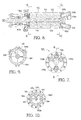
FIG. 6 is an idealized cross-sectional view of a cartridge in accordance with the invention, showing functional partitioning thereof; -
FIG. 7 is a plan view of a first end cap of the system shown inFIG. 2 ; -
FIG. 8 is a second longitudinal view taken along line 8-8 inFIG. 7 ; -
FIG. 9 is a cross-sectional view taken along line 9-9 inFIG. 8 ; and -
FIG. 10 is a cross-sectional view taken along line 10-10 inFIG. 8 . - Corresponding reference characters indicate corresponding parts throughout the several views. The exemplification set out herein illustrates one preferred embodiment of the invention, in one form, and such exemplification is not to be construed as limiting the scope of the invention in any manner.
- Referring to
FIG. 1 , aschematic flow chart 100 is shown for use of a gas-adsorption system 102, such as shown inFIG. 2 , in accordance with the invention, exemplarily employed in the present example as an H2S scrubber in areformate gas stream 104a being generated from sulfur-containinghydrocarbon fuel 106 bycatalytic reformer 108 for supplying sulfur-freereformate fuel 104b to the anode of a solid oxidefuel cell stack 110.Anode tailgas 112 is divided, afirst portion 112a being recycled into the intake ofreformer 108 and asecond portion 112b being sent tocombustor 114 for burning and discharge toatmosphere 116.Fresh air 118a is supplied to the cathode ofstack 110, and heatedcathode exhaust air 118b is directed throughsystem 102 and thence tocombustor 114 where it is combined for combustion with secondanode tailgas portion 112b. - Still referring to
FIG. 1 , it is seen thatsystem 102 comprises three treatment sections: a selectiveadsorbing section 103, anoxidative regeneration section 105, and areductive regeneration section 107. For removing H2S from a gas stream such as reformate 104a insection 103, an excellent adsorbing medium is nickel stabilized with a rare earth metal; however, in regeneration of the medium by the passage ofair 118b throughsection 105 the medium becomes oxidized and therefore must be chemically reduced inreductive section 107 prior to being used again for adsorption insection 103. In dealing with reformate, as in the present example, the reformate itself is a highly reducing composition, comprising a high percentage of elemental hydrogen; thus, the reformate upon leavingadsorption section 103 is simply directed back throughsection 107 where the reformate reduces the nickel catalyst prior to being sent to SOFC 110 asfuel 104b. Obviously, in other applications of a continuous adsorption system in accordance with the invention, other means for reducing the nickel catalyst will occur to those of ordinary skill in the art and such other means are fully comprehended by the invention. In the present application, however, reformate is a convenient reductant. - Referring to
FIG. 2 ,system 102 comprises a gas-treatingportion 102a and arotary actuator portion 102b for rotating a cartridge within a housing. In high-temperature applications, such as in the desulfurizing of hot reformate,portion 102a must necessarily be disposed in an overall high-temperature environment, for example, 500-1000°C; however, the rotary actuator is preferably placed in a cooler environment outside of the hot zone (which typically contains theSOFC stack 110 as well). Hence, in a currently-preferredembodiment 102,portions insulative barrier 120, and only an actuator shaft extends throughbarrier 120 to rotate theportion 102b as described below. - Referring now to
FIGS. 3 through 10 ,system 102 comprises acylindrical housing 122 having an integralfirst end cap 124 at a first end and afirst flange 126 at the opposite end.First end cap 124 is provided withnippled ports nippled ports Second end cap 130 comprises asecond flange 132 for matably sealing tofirst flange 126. Anactuator shaft 134 extends through a central opening insecond end cap 130 and is rotatably supported at a distal end thereof in asocket 136 formed infirst end cap 124. Shaft 134 is urged intosocket 136 by abias spring 138 operative against ashaft flange 140 and retained within a dynamically-sealingbellows 142 by apacking gland 144 and packingflange 146. Agas flow disk 148 is disposed onshaft 134 and is engaged in non-rotating relationship withinhousing 122, permittingshaft 134 to be rotated throughdisk 148. Preferably,shaft 134 includes ashoulder 150 for axiallyengaging flow disk 148 to urge the disk towardfirst end cap 124. - A gas-adsorbing
cartridge 152 is disposed within acylindrical shell 154, and both are disposed withinhousing 122 in rotational sealing relationship betweeninner face 156 offirst end cap 124 andinner face 158 offlow disk 148. Cartridge 152 is supported on aportion 160 ofshaft 134 having flats or other means forengaging cartridge 152. Thus,cartridge 152 may be rotated relative toend cap face 156 andflow disk face 158 by rotation ofshaft 134 by arotary actuator 135 during operation ofsystem 102 as described below. -
First end cap 124 is provided with a plurality ofcompartments 162a-162d in respective communication withports 128a-128d andcartridge 152, the compartments being defined by separatingribs 164. Similarly,flow disk 148 is provided with a plurality ofblind compartments 166a-166b in communication withcartridge 152 and defined by separatingribs 168. - Cartridge 152 is longitudinally permeable and circumferentially impermeable, and preferably is formed of a plurality of tubules or channels extending between
first end cap 124 andflow disk 148. A currently preferred cartridge is a honeycomb monolith formed preferably of ceramic and having a high surface area coated with nickel catalyst doped with rare earth metal for adsorption of H2S as described above. Such a cartridge is available from TDA Research, Inc., Wheat Ridge, Colorado, USA. - In operation of
system 102, and referring now toFIGS. 1-10 ,gaseous reformate 104a containing H2S is entered intocartridge 152 viaport 128b and flows through longitudinal channels ofcartridge 152 aligned withcompartment 162b andcompartment 166b.Compartment 166b acts as a plenum to distribute the reformate over a large percentage of the cross-sectional area ofcartridge 152 commensurate withcompartment 166b. The reformate flow is returned tocompartment 162a where it is gathered and directed viaport 128a to the anode ofSOFC 110. During passage through the channels aligned withcompartments system 102 and the flow rate of reformate. For example, a system having a volume of 3 liters supplying reformate to an SOFC operating at maximum power flow can desulfurize a reformate flow rate of about 18 liters per second. Preferably asulfur sensor 178 is provided incompartment 162a to alarm in the event of desulfurizing failure ofsystem 102 and to prevent thereby sulfur contamination of the anode inSOFC 110. Within the scope of the invention, reformate flow may be directed in either direction throughports - Synchronous with the just-described desulfurizing process, air (preferably
heated air 118b exhausted from the SOFC cathode) is directed intoport 128c and thence into cartridge channels aligned withcompartments compartment 162c, is turned incompartment 166a, flows back through parallel channels aligned withcompartment 162d, and is gathered and directed viaport 128d tocombustor 114. The air flowing through these channels strips the adsorbed H2S from the catalyst and carries it to the combustor. In the process, the catalyst is reversibly oxidized. Within the scope of the invention, air flow may be directed in either direction throughports - During operation of
system 102,cartridge 152 is rotated betweenfirst end cap 124 andflow disk 132 by rotation ofshaft 134 in thedirection 180 shown inFIG. 6 . Rotation may be stepwise or continuous. An exemplary system requires a rotation rate of about 1 revolution per hour. It will be seen that rotation causes a) adsorber catalyst carrying adsorbed H2S to be exposed to air flow that purges the H2S from the medium and also oxidizes the medium; b) oxidized catalyst to be exposed again to reducing reformate that reduces the oxidized catalyst and converts the oxide to water which is carried beneficially into the SOFC with the desulfurized reformate. As the oxidized catalyst is progressively reduced by reformate it becomes capable again of adsorbing H2S, continuing the adsorption/regeneration cycle. - Thus, a system in accordance with the invention is capable of continuously selectively adsorbing a specific gas entity from a mixture of gases, and is especially useful in continuously desulfurizing reformate derived from hydrocarbon fuels containing sulfur.
- While the invention has been described by reference to various specific embodiments, it should be understood that numerous changes may be made within the spirit and scope of the inventive concepts described. Accordingly, it is intended that the invention not be limited to the described embodiments, but will have full scope defined by the language of the following claims.
Claims (16)
- A system for continuous adsorption of a given gas species from a flowing mixture of gas species, comprising:a) a housing having first and second end plates disposed at opposite ends thereof, wherein at least one of said first and second end plates includes a plurality of ports for entrance and exit of said flowing mixture of gas species and for entrance and exit of at least one flowing regenerative gas species;b) a reversibly adsorptive medium rotatably disposed within said housing between said first and second end plates; andc) a rotator for rotating said reversibly adsorptive medium into and out of selective communication with said entrance and exit ports for said at least one flowing regenerative gas species and said entrance and exit ports for said flowing mixture of gas species.
- A system in accordance with Claim 1 wherein at any given time a first portion of said reversibly adsorptive medium is positioned in communication with said entrance and exit ports for said flowing regenerative gas species to regenerate said first portion, and wherein a second portion of said reversibly adsorptive medium is positioned in communication with said entrance and exit ports for said flowing mixture of gas species to adsorb said given gas species therefrom.
- A system in accordance with Claim 1 wherein said flowing regenerative gas species includes an oxidant of said medium.
- A system in accordance with Claim 3 wherein said flowing regenerative gas species includes a reductant of said medium, and wherein said reductant is applied to said medium following application of said oxidant.
- A system in accordance with Claim 4 wherein said mixture of gas species is a hydrocarbon reformate including hydrogen sulfide, and wherein said given gas species is hydrogen sulfide, and wherein said oxidant in said flowing regenerative gas species is oxygen, and wherein said reductant in said flowing regenerative gas species is hydrogen.
- A system in accordance with Claim 5 wherein said hydrogen is provided by passage of said hydrogen reformate over said medium.
- A system in accordance with Claim 5 wherein said hydrocarbon reformate is derived by catalytic reforming of a sulfur-containing hydrocarbon fuel.
- A system in accordance with Claim 1 wherein said plurality of ports for entrance and exit of said flowing mixture of gas species and for entrance and exit of said flowing regenerative gas species are all disposed in said first end plate and wherein said second end plate is formed to cause flows of said mixture of gas species and flows of said regenerative gas species to be returned to said first end plate through said medium.
- A system in accordance with Claim 8 wherein said rotator for rotating comprises an actuator shaft supportive of said reversibly adsorptive medium and extending through said second end plate.
- A system in accordance with Claim 9 wherein said rotator for rotating further comprises a rotary actuator attached to said actuator shaft.
- A system in accordance with Claim 10 wherein said reversibly adsorptive medium is disposed in a first thermal environment and said rotary actuator is disposed in a second thermal environment, and wherein said first and second thermal environments are separated by a thermal barrier, and wherein said actuator shaft extends through said thermal barrier between said rotary actuator and said reversibly adsorptive medium.
- A system in accordance with Claim 1 wherein said reversibly adsorptive medium comprises an inert substrate formed as a plurality of channels extending longitudinally of said substrate and wherein walls of said channels are covered by a material reversibly adsorbent of said given gas species.
- A system in accordance with Claim 12 wherein said material reversibly adsorbent of said given gas species includes nickel.
- A system in accordance with Claim 13 wherein said material reversibly adsorbent of said given gas species further includes a rare earth element.
- In a system for continuous adsorption of a given gas species from a flowing mixture of gas species,wherein said system includes a housing having first and second end plates disposed at opposite ends thereof, wherein at least one of said first and second end plates includes a plurality of ports for entrance and exit of said flowing mixture of gas species and for entrance and exit of a flowing regenerative gas species, andwherein said system further includes a reversibly adsorptive medium rotatably disposed within said housing, andwherein said system further includes a rotator for rotating said reversibly adsorptive medium into and out of selective communication with said entrance and exit ports for said flowing regenerative gas species and said entrance and exit ports for said flowing mixture of gas species,a method for operating said system comprising the steps of:a) exposing a first portion of said medium to said flowing mixture of gas species while simultaneously exposing a second portion of said medium to said flowing regenerative gas species;b) rotating said medium to cause said first portion of said medium to become exposed to said flowing regenerative gas species and to cause said second portion of said medium to become exposed to said flowing mixture of gas species; andc) periodically repeating steps a) and b) sequentially.
- A fuel cell system, comprising:a) a fuel cell stack;b) a catalytic reformer for reforming a sulfur-containing hydrocarbon fuel to provide reformate fuel to said fuel cell stack; andc) apparatus disposed between said catalytic reformer and said fuel cell stack for continuous adsorption of hydrogen sulfide from said reformate fuel, wherein said apparatus includesa housing having first and second end plates disposed at opposite ends thereof, wherein at least one of said first and second end plates includes a plurality of ports for entrance and exit of said reformate and for entrance and exit of regenerative air,a medium rotatably disposed within said housing for reversible adsorption of hydrogen sulfide from said reformate fuel, anda rotator for rotating said reversibly adsorptive medium into and out of selective communication with said entrance and exit ports for said regenerative air and said entrance and exit ports for said reformate.
Applications Claiming Priority (1)
| Application Number | Priority Date | Filing Date | Title |
|---|---|---|---|
| US11/804,885 US7972422B2 (en) | 2007-05-21 | 2007-05-21 | System for continuous removal of a specific gas from a flowing mixture of gases |
Publications (2)
| Publication Number | Publication Date |
|---|---|
| EP1997550A1 true EP1997550A1 (en) | 2008-12-03 |
| EP1997550B1 EP1997550B1 (en) | 2018-06-27 |
Family
ID=39714150
Family Applications (1)
| Application Number | Title | Priority Date | Filing Date |
|---|---|---|---|
| EP08154626.9A Active EP1997550B1 (en) | 2007-05-21 | 2008-04-16 | System for continuous removal of a specific gas from a flowing mixture of gases |
Country Status (2)
| Country | Link |
|---|---|
| US (1) | US7972422B2 (en) |
| EP (1) | EP1997550B1 (en) |
Cited By (2)
| Publication number | Priority date | Publication date | Assignee | Title |
|---|---|---|---|---|
| EP2110361A3 (en) * | 2008-04-14 | 2010-10-27 | Delphi Technologies, Inc. | Cartridge adsorber system for removing hydrogen sulfide from reformate |
| US8940072B2 (en) | 2009-02-27 | 2015-01-27 | Inventys Thermal Technologies Inc. | Parallel passage fluid contactor structure |
Families Citing this family (3)
| Publication number | Priority date | Publication date | Assignee | Title |
|---|---|---|---|---|
| US8308848B1 (en) | 2009-11-27 | 2012-11-13 | Tda Research, Inc. | High temperature gas desulfurization sorbents |
| CN112191072A (en) * | 2020-10-14 | 2021-01-08 | 郭鸿磊 | Integrated organic waste gas adsorption and regeneration equipment |
| CA3264434A1 (en) | 2022-08-23 | 2024-02-29 | ExxonMobil Technology and Engineering Company | Rotary bed for direct capture of co2 from air and method thereof |
Citations (4)
| Publication number | Priority date | Publication date | Assignee | Title |
|---|---|---|---|---|
| US4452612A (en) * | 1982-09-22 | 1984-06-05 | Cubemco, Inc. | Separation and purification of gases and vapors by continuous pressure-swing adsorption |
| US20010023640A1 (en) * | 1999-12-09 | 2001-09-27 | Questair Technologies Inc. | Life support oxygen concentrator |
| WO2001083365A2 (en) * | 2000-05-02 | 2001-11-08 | Honeywell International Inc. | Method for removal of carbon monoxide from reformate |
| US20040179998A1 (en) * | 2003-03-14 | 2004-09-16 | Gittleman Craig S. | Fuel processor module for hydrogen production for a fuel cell engine using pressure swing adsorption |
Family Cites Families (7)
| Publication number | Priority date | Publication date | Assignee | Title |
|---|---|---|---|---|
| US4816353A (en) * | 1986-05-14 | 1989-03-28 | International Fuel Cells Corporation | Integrated fuel cell and fuel conversion apparatus |
| BE1005764A3 (en) * | 1992-04-15 | 1994-01-18 | Atlas Copco Airpower Nv | Device for drying a gas. |
| SG104251A1 (en) * | 1998-01-26 | 2004-06-21 | Kankyo Co Ltd | Method and apparatus for dehumidifying air |
| US6083300A (en) * | 1998-08-25 | 2000-07-04 | Gas Research Institute | Dual mode air treatment apparatus and method |
| US6428761B1 (en) * | 2000-09-29 | 2002-08-06 | Engelhard Corporation | Process for reduction of gaseous sulfur compounds |
| US6689194B2 (en) * | 2001-03-12 | 2004-02-10 | Motorola, Inc | Fuel cell system having a replaceable getter element for purifying the fuel supply |
| US7896952B2 (en) * | 2008-04-14 | 2011-03-01 | Delphi Technologies, Inc. | Cartridge adsorber system for removing hydrogen sulfide from reformate |
-
2007
- 2007-05-21 US US11/804,885 patent/US7972422B2/en active Active
-
2008
- 2008-04-16 EP EP08154626.9A patent/EP1997550B1/en active Active
Patent Citations (4)
| Publication number | Priority date | Publication date | Assignee | Title |
|---|---|---|---|---|
| US4452612A (en) * | 1982-09-22 | 1984-06-05 | Cubemco, Inc. | Separation and purification of gases and vapors by continuous pressure-swing adsorption |
| US20010023640A1 (en) * | 1999-12-09 | 2001-09-27 | Questair Technologies Inc. | Life support oxygen concentrator |
| WO2001083365A2 (en) * | 2000-05-02 | 2001-11-08 | Honeywell International Inc. | Method for removal of carbon monoxide from reformate |
| US20040179998A1 (en) * | 2003-03-14 | 2004-09-16 | Gittleman Craig S. | Fuel processor module for hydrogen production for a fuel cell engine using pressure swing adsorption |
Cited By (3)
| Publication number | Priority date | Publication date | Assignee | Title |
|---|---|---|---|---|
| EP2110361A3 (en) * | 2008-04-14 | 2010-10-27 | Delphi Technologies, Inc. | Cartridge adsorber system for removing hydrogen sulfide from reformate |
| US7896952B2 (en) | 2008-04-14 | 2011-03-01 | Delphi Technologies, Inc. | Cartridge adsorber system for removing hydrogen sulfide from reformate |
| US8940072B2 (en) | 2009-02-27 | 2015-01-27 | Inventys Thermal Technologies Inc. | Parallel passage fluid contactor structure |
Also Published As
| Publication number | Publication date |
|---|---|
| US20080292923A1 (en) | 2008-11-27 |
| US7972422B2 (en) | 2011-07-05 |
| EP1997550B1 (en) | 2018-06-27 |
Similar Documents
| Publication | Publication Date | Title |
|---|---|---|
| KR100796110B1 (en) | High Capacity Sulfur Adsorbent Bed and Gas Desulfurization Method | |
| CN101578351B (en) | Reforming Sour Hydrocarbons Using Sulfur Tolerant Catalysts | |
| EP1997550B1 (en) | System for continuous removal of a specific gas from a flowing mixture of gases | |
| JP4008210B2 (en) | Fuel cell power generation system | |
| US7901566B2 (en) | Reforming sulfur-containing hydrocarbons using a sulfur resistant catalyst | |
| CN101849314A (en) | Fuel process apparatus of multiple desulfurizers and fuel cell system with the same | |
| JPH08138703A (en) | Fuel cell generator | |
| US7896952B2 (en) | Cartridge adsorber system for removing hydrogen sulfide from reformate | |
| JP2008186701A (en) | Fuel cell power generator and method of operating the same | |
| JP3956755B2 (en) | Fuel cell power generation system | |
| EP2616158B1 (en) | Method and apparatus for removing contaminant from fluid | |
| JP2012136560A (en) | Desulfurization system, and method of controlling the same | |
| KR101134739B1 (en) | Self regenerating desulfurizer for gaseous fuels | |
| JP5632688B2 (en) | Desulfurization system and control method of desulfurization system | |
| EP2614876B1 (en) | High-temperature and high-pressure system for desulfurisation and dehalogenation of gas | |
| JP2007103078A (en) | Fuel cell system | |
| JP5505779B2 (en) | Desulfurizer and fuel cell system equipped with the same | |
| ES2307458B2 (en) | METHOD FOR THE ELIMINATION ORGANOCLORED COMPOUNDS IN GASEOUS EMISSIONS BY ADSORTION AND REDUCTIVE REGENERATION OF THE ADSORBENT. | |
| JP2006088038A (en) | Desulfurization method | |
| JPH0689733A (en) | Molten salt fuel cell device |
Legal Events
| Date | Code | Title | Description |
|---|---|---|---|
| PUAI | Public reference made under article 153(3) epc to a published international application that has entered the european phase |
Free format text: ORIGINAL CODE: 0009012 |
|
| AK | Designated contracting states |
Kind code of ref document: A1 Designated state(s): AT BE BG CH CY CZ DE DK EE ES FI FR GB GR HR HU IE IS IT LI LT LU LV MC MT NL NO PL PT RO SE SI SK TR |
|
| AX | Request for extension of the european patent |
Extension state: AL BA MK RS |
|
| 17P | Request for examination filed |
Effective date: 20090603 |
|
| 17Q | First examination report despatched |
Effective date: 20090630 |
|
| AKX | Designation fees paid |
Designated state(s): AT BE BG CH CY CZ DE DK EE ES FI FR GB GR HR HU IE IS IT LI LT LU LV MC MT NL NO PL PT RO SE SI SK TR |
|
| GRAP | Despatch of communication of intention to grant a patent |
Free format text: ORIGINAL CODE: EPIDOSNIGR1 |
|
| STAA | Information on the status of an ep patent application or granted ep patent |
Free format text: STATUS: GRANT OF PATENT IS INTENDED |
|
| INTG | Intention to grant announced |
Effective date: 20180102 |
|
| GRAS | Grant fee paid |
Free format text: ORIGINAL CODE: EPIDOSNIGR3 |
|
| GRAA | (expected) grant |
Free format text: ORIGINAL CODE: 0009210 |
|
| STAA | Information on the status of an ep patent application or granted ep patent |
Free format text: STATUS: THE PATENT HAS BEEN GRANTED |
|
| AK | Designated contracting states |
Kind code of ref document: B1 Designated state(s): AT BE BG CH CY CZ DE DK EE ES FI FR GB GR HR HU IE IS IT LI LT LU LV MC MT NL NO PL PT RO SE SI SK TR |
|
| REG | Reference to a national code |
Ref country code: GB Ref legal event code: FG4D |
|
| REG | Reference to a national code |
Ref country code: AT Ref legal event code: REF Ref document number: 1011809 Country of ref document: AT Kind code of ref document: T Effective date: 20180715 |
|
| REG | Reference to a national code |
Ref country code: DE Ref legal event code: R096 Ref document number: 602008055736 Country of ref document: DE |
|
| REG | Reference to a national code |
Ref country code: IE Ref legal event code: FG4D |
|
| PG25 | Lapsed in a contracting state [announced via postgrant information from national office to epo] |
Ref country code: SE Free format text: LAPSE BECAUSE OF FAILURE TO SUBMIT A TRANSLATION OF THE DESCRIPTION OR TO PAY THE FEE WITHIN THE PRESCRIBED TIME-LIMIT Effective date: 20180627 Ref country code: BG Free format text: LAPSE BECAUSE OF FAILURE TO SUBMIT A TRANSLATION OF THE DESCRIPTION OR TO PAY THE FEE WITHIN THE PRESCRIBED TIME-LIMIT Effective date: 20180927 Ref country code: FI Free format text: LAPSE BECAUSE OF FAILURE TO SUBMIT A TRANSLATION OF THE DESCRIPTION OR TO PAY THE FEE WITHIN THE PRESCRIBED TIME-LIMIT Effective date: 20180627 Ref country code: NO Free format text: LAPSE BECAUSE OF FAILURE TO SUBMIT A TRANSLATION OF THE DESCRIPTION OR TO PAY THE FEE WITHIN THE PRESCRIBED TIME-LIMIT Effective date: 20180927 Ref country code: LT Free format text: LAPSE BECAUSE OF FAILURE TO SUBMIT A TRANSLATION OF THE DESCRIPTION OR TO PAY THE FEE WITHIN THE PRESCRIBED TIME-LIMIT Effective date: 20180627 |
|
| REG | Reference to a national code |
Ref country code: NL Ref legal event code: MP Effective date: 20180627 |
|
| REG | Reference to a national code |
Ref country code: LT Ref legal event code: MG4D |
|
| PG25 | Lapsed in a contracting state [announced via postgrant information from national office to epo] |
Ref country code: GR Free format text: LAPSE BECAUSE OF FAILURE TO SUBMIT A TRANSLATION OF THE DESCRIPTION OR TO PAY THE FEE WITHIN THE PRESCRIBED TIME-LIMIT Effective date: 20180928 Ref country code: HR Free format text: LAPSE BECAUSE OF FAILURE TO SUBMIT A TRANSLATION OF THE DESCRIPTION OR TO PAY THE FEE WITHIN THE PRESCRIBED TIME-LIMIT Effective date: 20180627 Ref country code: LV Free format text: LAPSE BECAUSE OF FAILURE TO SUBMIT A TRANSLATION OF THE DESCRIPTION OR TO PAY THE FEE WITHIN THE PRESCRIBED TIME-LIMIT Effective date: 20180627 |
|
| REG | Reference to a national code |
Ref country code: DE Ref legal event code: R081 Ref document number: 602008055736 Country of ref document: DE Owner name: APTIV TECHNOLOGIES LIMITED, BB Free format text: FORMER OWNER: DELPHI TECHNOLOGIES, INC., TROY, MICH., US |
|
| REG | Reference to a national code |
Ref country code: AT Ref legal event code: MK05 Ref document number: 1011809 Country of ref document: AT Kind code of ref document: T Effective date: 20180627 |
|
| PG25 | Lapsed in a contracting state [announced via postgrant information from national office to epo] |
Ref country code: NL Free format text: LAPSE BECAUSE OF FAILURE TO SUBMIT A TRANSLATION OF THE DESCRIPTION OR TO PAY THE FEE WITHIN THE PRESCRIBED TIME-LIMIT Effective date: 20180627 |
|
| PG25 | Lapsed in a contracting state [announced via postgrant information from national office to epo] |
Ref country code: AT Free format text: LAPSE BECAUSE OF FAILURE TO SUBMIT A TRANSLATION OF THE DESCRIPTION OR TO PAY THE FEE WITHIN THE PRESCRIBED TIME-LIMIT Effective date: 20180627 Ref country code: CZ Free format text: LAPSE BECAUSE OF FAILURE TO SUBMIT A TRANSLATION OF THE DESCRIPTION OR TO PAY THE FEE WITHIN THE PRESCRIBED TIME-LIMIT Effective date: 20180627 Ref country code: RO Free format text: LAPSE BECAUSE OF FAILURE TO SUBMIT A TRANSLATION OF THE DESCRIPTION OR TO PAY THE FEE WITHIN THE PRESCRIBED TIME-LIMIT Effective date: 20180627 Ref country code: SK Free format text: LAPSE BECAUSE OF FAILURE TO SUBMIT A TRANSLATION OF THE DESCRIPTION OR TO PAY THE FEE WITHIN THE PRESCRIBED TIME-LIMIT Effective date: 20180627 Ref country code: EE Free format text: LAPSE BECAUSE OF FAILURE TO SUBMIT A TRANSLATION OF THE DESCRIPTION OR TO PAY THE FEE WITHIN THE PRESCRIBED TIME-LIMIT Effective date: 20180627 Ref country code: PL Free format text: LAPSE BECAUSE OF FAILURE TO SUBMIT A TRANSLATION OF THE DESCRIPTION OR TO PAY THE FEE WITHIN THE PRESCRIBED TIME-LIMIT Effective date: 20180627 Ref country code: IS Free format text: LAPSE BECAUSE OF FAILURE TO SUBMIT A TRANSLATION OF THE DESCRIPTION OR TO PAY THE FEE WITHIN THE PRESCRIBED TIME-LIMIT Effective date: 20181027 |
|
| REG | Reference to a national code |
Ref country code: GB Ref legal event code: 732E Free format text: REGISTERED BETWEEN 20190117 AND 20190123 |
|
| REG | Reference to a national code |
Ref country code: GB Ref legal event code: 732E Free format text: REGISTERED BETWEEN 20190124 AND 20190130 |
|
| PG25 | Lapsed in a contracting state [announced via postgrant information from national office to epo] |
Ref country code: ES Free format text: LAPSE BECAUSE OF FAILURE TO SUBMIT A TRANSLATION OF THE DESCRIPTION OR TO PAY THE FEE WITHIN THE PRESCRIBED TIME-LIMIT Effective date: 20180627 Ref country code: IT Free format text: LAPSE BECAUSE OF FAILURE TO SUBMIT A TRANSLATION OF THE DESCRIPTION OR TO PAY THE FEE WITHIN THE PRESCRIBED TIME-LIMIT Effective date: 20180627 |
|
| REG | Reference to a national code |
Ref country code: DE Ref legal event code: R097 Ref document number: 602008055736 Country of ref document: DE |
|
| PLBE | No opposition filed within time limit |
Free format text: ORIGINAL CODE: 0009261 |
|
| STAA | Information on the status of an ep patent application or granted ep patent |
Free format text: STATUS: NO OPPOSITION FILED WITHIN TIME LIMIT |
|
| PG25 | Lapsed in a contracting state [announced via postgrant information from national office to epo] |
Ref country code: DK Free format text: LAPSE BECAUSE OF FAILURE TO SUBMIT A TRANSLATION OF THE DESCRIPTION OR TO PAY THE FEE WITHIN THE PRESCRIBED TIME-LIMIT Effective date: 20180627 |
|
| 26N | No opposition filed |
Effective date: 20190328 |
|
| PG25 | Lapsed in a contracting state [announced via postgrant information from national office to epo] |
Ref country code: SI Free format text: LAPSE BECAUSE OF FAILURE TO SUBMIT A TRANSLATION OF THE DESCRIPTION OR TO PAY THE FEE WITHIN THE PRESCRIBED TIME-LIMIT Effective date: 20180627 |
|
| REG | Reference to a national code |
Ref country code: CH Ref legal event code: PL |
|
| REG | Reference to a national code |
Ref country code: BE Ref legal event code: MM Effective date: 20190430 |
|
| PG25 | Lapsed in a contracting state [announced via postgrant information from national office to epo] |
Ref country code: LU Free format text: LAPSE BECAUSE OF NON-PAYMENT OF DUE FEES Effective date: 20190416 Ref country code: MC Free format text: LAPSE BECAUSE OF FAILURE TO SUBMIT A TRANSLATION OF THE DESCRIPTION OR TO PAY THE FEE WITHIN THE PRESCRIBED TIME-LIMIT Effective date: 20180627 |
|
| PG25 | Lapsed in a contracting state [announced via postgrant information from national office to epo] |
Ref country code: LI Free format text: LAPSE BECAUSE OF NON-PAYMENT OF DUE FEES Effective date: 20190430 Ref country code: CH Free format text: LAPSE BECAUSE OF NON-PAYMENT OF DUE FEES Effective date: 20190430 |
|
| PG25 | Lapsed in a contracting state [announced via postgrant information from national office to epo] |
Ref country code: BE Free format text: LAPSE BECAUSE OF NON-PAYMENT OF DUE FEES Effective date: 20190430 |
|
| PG25 | Lapsed in a contracting state [announced via postgrant information from national office to epo] |
Ref country code: TR Free format text: LAPSE BECAUSE OF FAILURE TO SUBMIT A TRANSLATION OF THE DESCRIPTION OR TO PAY THE FEE WITHIN THE PRESCRIBED TIME-LIMIT Effective date: 20180627 |
|
| PG25 | Lapsed in a contracting state [announced via postgrant information from national office to epo] |
Ref country code: IE Free format text: LAPSE BECAUSE OF NON-PAYMENT OF DUE FEES Effective date: 20190416 |
|
| PG25 | Lapsed in a contracting state [announced via postgrant information from national office to epo] |
Ref country code: PT Free format text: LAPSE BECAUSE OF FAILURE TO SUBMIT A TRANSLATION OF THE DESCRIPTION OR TO PAY THE FEE WITHIN THE PRESCRIBED TIME-LIMIT Effective date: 20181029 |
|
| PG25 | Lapsed in a contracting state [announced via postgrant information from national office to epo] |
Ref country code: CY Free format text: LAPSE BECAUSE OF FAILURE TO SUBMIT A TRANSLATION OF THE DESCRIPTION OR TO PAY THE FEE WITHIN THE PRESCRIBED TIME-LIMIT Effective date: 20180627 |
|
| PG25 | Lapsed in a contracting state [announced via postgrant information from national office to epo] |
Ref country code: HU Free format text: LAPSE BECAUSE OF FAILURE TO SUBMIT A TRANSLATION OF THE DESCRIPTION OR TO PAY THE FEE WITHIN THE PRESCRIBED TIME-LIMIT; INVALID AB INITIO Effective date: 20080416 Ref country code: MT Free format text: LAPSE BECAUSE OF FAILURE TO SUBMIT A TRANSLATION OF THE DESCRIPTION OR TO PAY THE FEE WITHIN THE PRESCRIBED TIME-LIMIT Effective date: 20180627 |
|
| P01 | Opt-out of the competence of the unified patent court (upc) registered |
Effective date: 20230425 |
|
| PGFP | Annual fee paid to national office [announced via postgrant information from national office to epo] |
Ref country code: DE Payment date: 20250313 Year of fee payment: 18 |
|
| PGFP | Annual fee paid to national office [announced via postgrant information from national office to epo] |
Ref country code: GB Payment date: 20250410 Year of fee payment: 18 |
|
| PGFP | Annual fee paid to national office [announced via postgrant information from national office to epo] |
Ref country code: FR Payment date: 20250404 Year of fee payment: 18 |
|
| REG | Reference to a national code |
Ref country code: DE Ref legal event code: R081 Ref document number: 602008055736 Country of ref document: DE Owner name: APTIV TECHNOLOGIES AG, CH Free format text: FORMER OWNER: APTIV TECHNOLOGIES LIMITED, ST. MICHAEL, BB |