EP1997518A1 - Gravity driven fluid supply vessel for dispensing an aromatic odor neutralizer - Google Patents
Gravity driven fluid supply vessel for dispensing an aromatic odor neutralizer Download PDFInfo
- Publication number
- EP1997518A1 EP1997518A1 EP08156746A EP08156746A EP1997518A1 EP 1997518 A1 EP1997518 A1 EP 1997518A1 EP 08156746 A EP08156746 A EP 08156746A EP 08156746 A EP08156746 A EP 08156746A EP 1997518 A1 EP1997518 A1 EP 1997518A1
- Authority
- EP
- European Patent Office
- Prior art keywords
- vessel
- wall
- dispensing
- vaporizer
- vaporizer according
- Prior art date
- Legal status (The legal status is an assumption and is not a legal conclusion. Google has not performed a legal analysis and makes no representation as to the accuracy of the status listed.)
- Withdrawn
Links
Images









Classifications
-
- A—HUMAN NECESSITIES
- A61—MEDICAL OR VETERINARY SCIENCE; HYGIENE
- A61L—METHODS OR APPARATUS FOR STERILISING MATERIALS OR OBJECTS IN GENERAL; DISINFECTION, STERILISATION OR DEODORISATION OF AIR; CHEMICAL ASPECTS OF BANDAGES, DRESSINGS, ABSORBENT PADS OR SURGICAL ARTICLES; MATERIALS FOR BANDAGES, DRESSINGS, ABSORBENT PADS OR SURGICAL ARTICLES
- A61L9/00—Disinfection, sterilisation or deodorisation of air
- A61L9/015—Disinfection, sterilisation or deodorisation of air using gaseous or vaporous substances, e.g. ozone
- A61L9/04—Disinfection, sterilisation or deodorisation of air using gaseous or vaporous substances, e.g. ozone using substances evaporated in the air without heating
- A61L9/12—Apparatus, e.g. holders, therefor
- A61L9/127—Apparatus, e.g. holders, therefor comprising a wick
Definitions
- the present invention relates to construction and arrangement of parts for a dispenser apparatus providing aerodynamic air passages to communicate with an evaporation chamber in a vaporizer and, more particularly, to a gravity driven fluid supply vessel for maintaining a supply of volatile liquid in a storage cup containing an edge portion of a wick for broadcasting the volatile liquid along the evaporation chamber.
- a dispenser for volatile fluid is disclosed in three related United States Patent Nos. 5,533,705 ; 5,816,845 and 6,105,916 and provides a drive selectively using a large or small motor providing an air stream for generating vapor from a wick, ceramic wafers, or discs containing vaporizable deodorant reversible mounting back to back.
- Socket assemblies provide a socket for a motor of larger dimensions and a socket for a motor of smaller dimensions.
- a frame for a cabinet comprised of separate back plate, top member and bottom member of a resilient plastic so that the top member and bottom member are snap-locked to the back plate and secured further by projections from the top and bottom members in slots in the back plate.
- the bottom member is a liquid tight tray capable of processing deodorants in bottles through wicks or can with wicks, absorbent surcotas and wafers.
- a battery-blower assembly is snap-locked to the back plate. The battery poles are joined to the wires from the blower-motor by clips using solder less connections.
- a framed fluid delivery device that is made up of a fluid-delivery cartridge for the timed-release delivery of a fluid.
- the fluid delivery cartridge retained by a frame assembly uses a base portion for the delivery of fluid released from a cartridge.
- the base secures the fluid delivery cartridge within the frame assembly proximate the end when fluid is released.
- the fluid-delivery cartridge has a bottom, a top, and sides, and a dispersion pad positioned proximate the bottom of the fluid-delivery cartridge that at least partially surrounds the sides of the fluid-delivery cartridge.
- a generator to generate gas is used for powered discharge of volatile liquid from the storage cell that is part of the fluid delivery cartridge.
- a dispenser for an aromatic odor neutralizer embodying an enhanced aerodynamic passage for the mixture of vapors of odor neutralizer fluid with an ambient airflow.
- an aromatic dispenser apparatus including the combination of a dispenser cover including an elongated convexly-shaped central body extended at each side by spaced apart walls with a vent there between for ventilating the interior of the dispenser cover, the dispenser cover further including end walls having access openings for ventilating the elongated convexly-shaped central body, an elongated frame including a receptacle section terminating at a mounting fixture for pivotal support of the dispenser cover between an opened position and an operating position, side guards projecting from the receptacle section to traverse the vent at each side of the of the dispenser cover when in the operating position, the side guards having apertures for ventilating a volume bounded between the side guards and the receptacle section, and a vaporizer including an evaporation chamber supplied with a volatile liquid by a vessel, the vaporizer being fixedly positioned by the mounting fixture to extend between the projecting side guards to infuse air venting from the dispenser cover and side guards with
- a vaporizer for an aromatic odor neutralizer including the combination of a vessel including a side wall joined with a first end wall to form a gaseous impervious chamber above a stored volume of volatile liquid bounded by a dispensing wall opposite the first end wall, a ventilating housing including a cylindrical side wall for receiving the vessel to form a vaporization chamber there between terminating at a liquid storage cup for volatile liquid dispensed from the vessel, a metering wall encircling the dispensing wall, the metering wall having at least one opening for an intermittent flow of air into the gaseous impervious chamber counter concurrent with a discharge of volatile fluid from the vessel to the liquid storage cup, an upstanding surface in the liquid storage cup for piercing the dispensing end wall, and a wick having a portion immersed in volatile liquid in the liquid storage cup while residing in the vaporization chamber.
- a vessel for dispensing a volatile liquid a vessel cap to allow access to liquid storage compartment of the vessel and forms an airtight seal with the vessel, the vessel cap being non reversible thread connected by interfering flexible prongs on mating threads that seat to prevent unthreading of the vessel cap, a weaken end wall in a protruding sleeve section at end of the vessel opposite the cap, a rectangular wick fashioned into a cylinder without creases, a cylindrical sidewall of the vessel contains spaced apart protruding rings that protrude to vary heights such that largest protruding height resides at the liquid discharge end of the vessel for stabilizing the position of the wick when encircling the vessel, the cylindrical sidewall extends to a metering portion having openings dispersed about the terminal edge for counter concurrent flows of air and volatile fluid, and a ventilating housing with a cup at one end forming a reservoir for volatile liquid
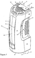
- Figures 1- 6 illustrated the preferred embodiment of an aromatic dispenser apparatus 10 that includes according to the present invention a dispenser cover 12 pivotally joined to a dispenser frame 14 constructed to receive fasteners, not shown and well known in the art, to secure the an aromatic dispenser apparatus to vertical wall surface of the room or other structure.
- the dispenser frame 14 is constructed to carry a vaporizer 16 and, if desired, the option of a fan module 18 ( Figure 5 ).
- the dispenser cover 12 is made up of a central body 20 that is elongated and convexly shaped in the direction of the elongated length.
- Body sidewall sections 22 and 23 are continuous along the opposed longitudinal sides of the central body 20 and define therewith a longitudinal cavity arranged to extend between top and bottom end walls 24 and 25 for forming a convection guide for airflow to each of the end walls.
- Body sidewall sections 22 and 23 are continuous along the opposed longitudinal sides with spaced apart walls 26, 27 and 28, 29, respectively.
- the spaced apart walls 26, 27 and 28, 29 together with the sidewall sections and the central body 20 take the form of circular ring sector shaped walls that form part of the elongated convexly shaped central body.
- Vents 30 and 31 at opposite sides of the central body ventilate the interior of the dispenser cover.
- Vent 30 is bounded by an edge portion of sidewall section 22 and by opposite sides by walls 26 and 27.
- Vent 31 is bound along an edge portion of sidewall section 23 and at opposite sides by walls 28 and 29.
- the top and bottom end walls 24 and 25 each have an array of parallel slots 32 and 33, respectively, bounded by a semicircular perimeter section containing curved slots 34 and terminal slots 35.
- the lengths of the parallel slots 32 in the top wall 24 as compared with the parallel slots 33 in the bottom wall 25 are reduced to provide a cavity bounded by spaced parallel arms 36 extending in interior of the convexly shaped central body 20 where each arm contains an aperture 37 in the extended end portion terminating at an curved end wall 38 forming a cam locking surface for pivotally mounting of the dispenser cover 12 to the dispenser frame 14.
- parallel arms 39 with hooked ends extend parallel with the lengths of the bars from the interior of the central body 20 for locking engagement with resilient latch bars 39A extending from the lower portion of the dispenser frame 14 and terminating with lateral hooked ends.
- the resilient lock bars 39A are displaced from locked engagement with the arms 39 by spaced bars 39B on a key 39C.
- spaced openings in the end wall 25 pass the bars 39B into an engagement with free ends of the lock bars 39A and deflect the hooked ends of the bars from last engagement with the ends of arms 39.
- the dispenser frame 14 takes the form of an elongated structure embodying a construction to form a receptacle section 40 terminating at a mounting fixture 41 for pivotal support of the dispenser cover 12 between the opened position shown in Figures 4 and 5 and an operating position shown in Figures 1-3 .
- the mounting fixture 41 takes the form of a rectangular block 42 contains a hinge pin 43 extending from each of the opposite lateral sides to extend into the aperture 37 in the extended end portion of the arms 36.
- the pivotal movement of the dispenser cover is controlled and limited by sliding contact between the curved end walls 38 along pressure bearing plate sections 44 that serve to hold the cam-locking surface formed on the ends of the curved end walls 38 for pivotally mounting of the dispenser cover 12 to the dispenser frame 14.
- Side guards 45 and 46 project from the receptacle section 40 to traverse the vents 30 and 31 at the sides of the dispenser cover 12 when in the operating position.
- the side guards 45 and 46 are bounded in a spaced relation by the sidewall extensions 26, 27 and 28, 29, which are coextensive with the end walls, and define opposed boundary edges of the vents.
- the side guards have apertures 45 and 46 for the passage of air currents and thereby ventilate a volume bounded between the side guards 45 and 46 and the receptacle section 40 wherein the vaporizer 16 is fixedly positioned by upper and lower spaced pairs of support hangers 47 and 48 to extend in a spaced apart relation between the projecting side guards.
- the side guards 45 and 46 will overlie an evaporation chamber in the vaporizer 16 when mounted on the receptacle section for exposing the vents at the sides of the dispenser cover 12 to ventilate vapors from the evaporation chamber.
- the interconnected relation between the vaporizer 16 and the receptacle section 40 is controlled by a proprietary array arrangement of key apertures 49 formed in a grid plate section 50 of the vaporizer for a go/no go inter engaging relationship with a protruding array of keys 51 mounted in the receptacle section 40.
- Underlying the receptacle section 40 are parallel T-shaped apertures 52 for interlocking engagement with enlarged heads of latch bars 53 extending from a drive frame 54.
- the drive frame has a molded configuration with a cavity to receive a motor 55 for driving fan blade assembly 56 mounted on the shaft of the motor to produce an air stream along the elongated convexly shaped central body of the dispenser cover 12.
- the fan blade assembly 56 includes helically arranged fan blades 57 extending from an annular sidewall of a hub 58.
- the fan blades 57 are orientated on the hub 58 so as to create an up draft of air when driven by the motor.
- Guide bars 59 project from opposite lateral sides of the dispenser frame 14 to stabilize and guide the dispenser cover 12 during pivotal movement to the closed position.
- the vaporizer 16 as shown in Figures 6-10 , includes evaporation chamber 60 having an elongated tubular configuration and the side guards 45 and 46 as show in Figure 5 have concave configurations transverse to the extended length of the evaporation chamber to partly wrap in an outwardly spaced relation about the evaporation chamber and thereby maximize the exposure of the ambient air flow to the volatile liquid conducted by a wick 61.
- the wick is generally rectangular shaped fibrous sheet of porous material fashioned into a cylinder without creases to reside in the evaporation chamber formed as a cylindrical cavity between a vessel 62 containing the supply of volatile liquid and a cylindrical ventilating housing 63 with a liquid storage cup 64 at one end forming a reservoir for volatile liquid dispensed from the vessel 62.
- the wick has a keystone shape to produce the configuration of a truncated cone to extend generally parallel with the correspondingly truncated conical shape of both the vessel 62 and the ventilated housing 63.
- a portion of the wick 61 is immersed in volatile liquid in the liquid storage cup 64 while residing in the vaporization chamber.
- the shape of the ventilating housing 63 is comprised of upright post members 65 extending from the rim of the cup 64 and dispersed about a circle defined by the rim of the cup.
- the rim of the cup is extended so as to prevent spillage of fluid from the interior of the cup.
- the post members 65 are interconnected by transverse ribs 66 forming an elongated tubular venting cage extending between the side guards 45 and 46.
- the post members 65 interconnected by the ribs 66 are arranged to provide that the cylindrical sidewall includes rectangular windows 66 for mounting the ventilating housing on the support hangers 47 and 48 in the receptacle section.
- the peripheral sidewall of the ventilating housing 63 includes parallel and radically outward extending stabilizer bars 68 to engage with the receptacle section when mounting the vaporizer to the elongated frame.
- the construction of the venting housing 63 produces an array venting windows 69 confronting the elongated convexly shaped central body of the dispenser cover 12.
- the sidewall of the vessel 62 or alternatively, the vessel 62 includes at least one wick support ring 70 in the vicinity of the cup 64 to maintain a desired spacing between of the wick from the confronting walls forming the evaporation chamber.
- FIGs 9-12 illustrate the vessel 62 incorporating one embodiment of an anti-spill sealing pad 73 the present invention.
- the anti-spill sealing pad 73 has a generally rectangular shape, but preferably keystone shaped with tapering end walls, and dimensioned with a length sufficient to encircle the outer periphery of the vessel 62 immediately adjacent the support ring 70 at the liquid discharged end of the vessel 62.
- the width of the sealing pad 73 is selected so as to traverse the height of the bottom row of venting windows 69.
- the sealing pad is preferably comprised of a layer 74a of elastic material such as expanded plastic, i.e.
- foamed plastic having a coating of an adhesive 74b on the opposed planar face surfaces to form an interconnected relation by adhering to the confronting surfaces of the vessel 62 and the wick 61.
- This interconnected relationship is fortified by the thickness of the sealing pad being equal but preferably slightly greater than the width of the gap between the contact site on the vessel 22 and wick 61 near the liquid discharge end of the vessel.
- the resilient property of the layer of elastic material 74a maintains the integrity of the interconnected relation and provide the desire anti-spill seal to avoid a flow of volatile liquid from the wick while immersed in a bath of volatile liquid in cup 64.
- the function of the wick 61 is to broadcast the volatile liquid about the entire surface area of the wick counter concurrent to prevailing gravitational force.
- the vaporizer 16 is placed in the operative position so that the major length of the wick remain parallel with the direction of gravity but in the event the vaporizer is place perpendicular to the operative position (horizontally) the liquid in the reservoir will propagate along the wick to such an extent that unwanted discharge may occur from the vaporizer.
- Figures 9 , 10 , 22 and 23 illustrate a tubular knife edge 75 projects in an upstanding manner from a bottom wall 76 of the cup 64 for piercing a weaken end wall section 77 in a dispensing wall 78 having the form of a protruding sleeve section extending from the end wall 78A of the vessel 62 opposite a vessel end cap 79, which is an optional alternative to an end wall integral with the side of the vessel.
- the tubular knife edge 75 is traversed in the hollow of the tubular shape by an upstanding rib 76 in the liquid storage cup to support in a suspend fashion a fractured portion of the dispensing end wall produced by the knife edge 75 and residing in the vessel.
- a metering wall 80 takes the form of a downward annular extension of the side of the vessel 62.
- the metering wall 80 is formed with openings 81 dispersed about the terminal edge for counter concurrent flows of air and volatile fluid. As shown in Figures 9 , 10 , 13 , 22 and 23 the metering wall 80 encircles the dispensing wall 78.
- the metering wall 80 has at least one opening, for an intermittent flow of air into the gaseous impervious chamber formed within the vessel above the volume of volatile stored therein counter concurrent with a discharge of volatile fluid from the vessel to the liquid storage cup.
- the dispensing wall 78 extends to a dispensing plane 85 recessed from a normally submerged metering plane 86 in the liquid contained in the storage cup.
- the metering wall 80 includes a plurality of openings 81 extending in a direction proceeding from the normally submerged metering plane 86 beyond the dispensing plane 85 for establishing the dispensing plane.
- openings 81 serve to control an intermittent flow of air by arrow A into the gaseous impervious chamber counter concurrent with a flow of volatile fluid by arrow F from the vessel to the liquid storage cup as shown in Figure 20 .
- FIG. 13-15 An alternative anti-spill function to that provided by the sealing pad 73 is shown in Figures 13-15 .
- a flow controller 87 is seated against the tubular sidewall of the vessel 62 in an overlying relation with the bottom wall 78A.
- the bottom wall 78A has a truncated conical shape with the conical truncation extending from the tubular side wall of the vessel and terminating at the dispensing wall 78.
- the flow controller 87 is comprised of a disc shaped fibrous matt 88 that is formed with a diameter sufficiently large to form an upturned annular rim 88A at the outer periphery when pressed into a tightly seating relation with the tubular side wall of the vessel 62, as shown in Figures 13 and 14 .
- the arrangement is such that the truncated conical form of the bottom wall forms a fluid flow path for liquid emerging from the underside of the fibrous matt 88 after wicking through the fibrous material of the matt and directs the fluid flow to the dispensing wall 78 where a central aperture 89 directly overlies the dispensing wall 78 and supplies a stream of fluid to the dispensing wall.
- the diameter of the aperture 89 is of the order of a small orifice so as to provide a valve metering function that prevents an unwanted surge flow through the dispensing wall in the event, for example, the vaporizer is placed in a non-operative horizontal orientation whereby fluid flow is greatly diminished as a result of the metering function of the aperture 89 as well as the wicking of fluid.
- the existence of the aperture 98 is preferred but can be eliminated when the fluid can permeate the fibrous matt at a rate that supplies sufficient fluid for the wicking process by the wick 61.
- the fibrous matt can take the form of a liquid permeable non-woven fiber such as paper, felt or the like. In the operation of the embodiment of the vessel 62 containing the flow controller 87, the fibrous nature of the disc allows wicking of fluid in combination with fluid flow from the aperture 89 through the dispensing wall and into the cup 64.
- a flanged vessel end cap 79 allows the access to a liquid storage compartment of the vessel 62 for the introduction of the volatile liquid into the vessel and forms an airtight seal with the vessel.
- the vessel end cap has threads 90 that engage with mating threads 91 on a rim portion 92 of the vessel.
- unthreading of the vessel end cap is prevented by the provision of upstanding barbs 93 at spaced intervals along the screw threads 90 corresponding to intervals of upstanding barbs 94 along the mating screw thread 91 on annular side wall formed by the rim portion 92.
- the operation of the cap moved into a locked vacuum tight condition on the vessel is diagrammatically illustrated by Figures 17-19 .
- Figure 17 projecting from the threads 90 on the cap are the barbs 93 and the threaded relationship with the threads 91 on the vessel operate to move the barb 94 into a confronting relationship with barbs 92.
- Figure 18 illustrates that travel of the threads 90 along the threads 91 cause the barbs 93 to collide with the barbs 94 and deform due to the elasticity of the plastic material forming the vessel and the vessel cap. The deformation eventually gives way to the passage of the barbs beyond the collision site.
- a flanged top end wall 96 of the vessels 97 and 98, respectively, is integrally formed with the sidewall 100 to provide the gaseous impervious chamber above a stored volume of volatile liquid in each of the vessels.
- the protruding sleeve section 101 of the vessel 97 shown in Figure 17 is provided with internal threads 102 to receive external threads 103 on a closure cap 104 containing a pierceable sealed film or membrane 105 from which there projects a metering wall 106 comprise of a half divided tube segment forming a protruding semicircular guard wall.
- the protruding sleeve section 107 of the vessel 98 shown in Figure 21 is provided with external threads 108 to receive internal threads in a rim 109 of a closure cap 110 containing a pierceable sealed film or membrane 111.
- the sidewall of the vessel is continued by the projecting metering wall 80 having the opening 81 dispersed about the terminal edge for counter concurrent flows of air and volatile liquid as described herein above.
- the ventilating housing 63 further includes snap ring segments 120 to engage and release each of the cavities located in a flanged portion 124 of the end cap 79 of the vessel 62 and top walls 96 at the end of the vessels 97 and 98 which are remote to the vessel ends constructed to dispense volatile liquid.
- the snap ring segments 120 fixedly position the metering wall at the dispensing end of the vessel at a predetermined spacing from floor of the liquid storage cup 64.
- Diametrically opposed tear segments 121 are between snap ring segments120.
- the tear segments 121 are joined to the snap ring segments by weakened walls that are easily fractured for removal to allow flexing of the snap ring segments when positioning the flanged end of the vessel between said snap ring segments.
- the snap ring segments 120 include a truncated conical support surface 122 that receives in a confronting relation a mating truncated conical surface 123 formed on the flanged portion of the end caps 79 and top wall 96 for suspending the vessel in the evaporation chamber.
- the vaporizer of the present invention is quickly replaced by removing the flange portion 124 of the cap 122 from the snap ring segment 120 and then inserting a replacement vaporizer by inserting the flange 124 in the snap ring segments as described herein above.
- the typical time for a total vaporization of the fluid in a newly installed vaporizer is 60 days with passive airflow and typically 30 days with a forced airflow by the fan assembly.
- a battery storage compartment is formed by opposed end walls 130 confronting pole pieces of a battery when seated against a cylindrical battery 131 container wall 132 terminating at spaced apart suspension arms 133 for support by the vaporizer 16.
- Strips 134 of electrically conductive material extending from the drive frame 54 toward the end walls 130 for contact with pole pieces of a battery when stored in a battery container wall 132.
- the electrically conductive strips 134 are retained by upstanding arms 135 spaced apart sufficiently to receive the end walls of the battery storage compartment.
- the end walls 130 of the battery storage compartment are arranged to expose the pole pieces of a battery while traversing opposite ends thereof.
- the upstanding arms 135 comprise a rectangular bar traversing one end of the battery compartment and a rectangular bar containing a centrally located indexing protuberance 136 to receive and uniquely define the location of a positive pole piece of a battery when located in the battery storage compartment.
- the drive frame 54 includes ridge aligned with one of the electrically conductive strips for passage into the indexing protuberance 136 to allow electrical connection between pole pieces of the battery and the electrically conductive strips. If desired, the battery may be eliminated and a step down transformer with an AC to DC rectifier can be direct connected to the fan motor.
- a wrapper 200 constructed of a sheet of heat shrinkable plastic material fashioned into a tubular shape that can be passed over the vaporizer to substantially completely envelope the outer cylindrical surface.
- the wrapper 200 stops short to allow exposure of the radically outward extending stabilizer bars 68.
- the wrapper is formed with diametrically opposed vertical perforations 201 and a perforation 202 encircling the mid portion of the tubular shape.
- the perforations 201 and 202 are used for controlling the extent to which ambient air can infiltrate the evaporation chamber.
- severing the wrapper 200 along perforation 202 allows removal of an upper half of the wrapper from the ventilating housing 63 of the vaporizer thus avoiding exposure of ambient air to the entire height of the evaporation chamber.
- the use of the wrapper serves to throttle back the speed of dispensing of the volatile liquid.
- Severing the wrapper along perforation 201 allows removal of the entire wrapper from the vaporizer thus exposure of ambient air to the entire height of the evaporation chamber and thus serves to maximizing the speed of dispensing of the volatile liquid.
Landscapes
- Health & Medical Sciences (AREA)
- Epidemiology (AREA)
- Life Sciences & Earth Sciences (AREA)
- Animal Behavior & Ethology (AREA)
- General Health & Medical Sciences (AREA)
- Public Health (AREA)
- Veterinary Medicine (AREA)
- Disinfection, Sterilisation Or Deodorisation Of Air (AREA)
- Catching Or Destruction (AREA)
Abstract
Description
- This application is a continuation-in-part of application serial no.
11/999,763 filed December 8, 2007 11/805,662, filed May 24, 2007 29/288,033, filed May 24, 2007 29/288,034, filed May 24, 2007 - The present invention relates to construction and arrangement of parts for a dispenser apparatus providing aerodynamic air passages to communicate with an evaporation chamber in a vaporizer and, more particularly, to a gravity driven fluid supply vessel for maintaining a supply of volatile liquid in a storage cup containing an edge portion of a wick for broadcasting the volatile liquid along the evaporation chamber.
- Description of the prior art: A dispenser for volatile fluid is disclosed in three related United States Patent Nos.
5,533,705 ;5,816,845 and6,105,916 and provides a drive selectively using a large or small motor providing an air stream for generating vapor from a wick, ceramic wafers, or discs containing vaporizable deodorant reversible mounting back to back. Socket assemblies provide a socket for a motor of larger dimensions and a socket for a motor of smaller dimensions. A frame for a cabinet comprised of separate back plate, top member and bottom member of a resilient plastic so that the top member and bottom member are snap-locked to the back plate and secured further by projections from the top and bottom members in slots in the back plate. The bottom member is a liquid tight tray capable of processing deodorants in bottles through wicks or can with wicks, absorbent surcotas and wafers. There is a bottle holder snap-locked to the underside of the top member. A battery-blower assembly is snap-locked to the back plate. The battery poles are joined to the wires from the blower-motor by clips using solder less connections. - More recently, as disclosed in Patent No.
6,957,779 , a framed fluid delivery device that is made up of a fluid-delivery cartridge for the timed-release delivery of a fluid. The fluid delivery cartridge retained by a frame assembly uses a base portion for the delivery of fluid released from a cartridge. The base secures the fluid delivery cartridge within the frame assembly proximate the end when fluid is released. The fluid-delivery cartridge has a bottom, a top, and sides, and a dispersion pad positioned proximate the bottom of the fluid-delivery cartridge that at least partially surrounds the sides of the fluid-delivery cartridge. A generator to generate gas is used for powered discharge of volatile liquid from the storage cell that is part of the fluid delivery cartridge. - Accordingly, it is an object of the present invention to provide a dispenser for an aromatic odor neutralizer embodying an enhanced aerodynamic passage for the mixture of vapors of odor neutralizer fluid with an ambient airflow.
- It is a further object of the present invention to provide an aromatic dispenser having side vents along an internal passage way extending between apertures in walls at the distal ends of the dispenser
- It is a further object of the present invention to provide a vaporizer having an evaporation chamber containing a wick traversing an anti spill seal for immersion in a bath of volatile liquid controlled by gravity feed.
- It is a further object of the present invention to provide a vaporizer having a vessel containing a fibrous matt in the form of a fluid permeable disc seated against a side wall thereof in an overlying relation with a dispensing wall for metering volatile fluid flow to a liquid storage cup.
- It is a further object of the present invention to provide an aromatic dispenser embodying a construction of parts to allow a choice to the desired dispersion rate of volatile liquid from a replaceable vaporizer cartridge by various means that include passive air currents, forced air by a motor driven fan, selective masking of areas an evaporation chamber supplied by a gravity driven dispenser for the volatile fluid.
- It is another object of the present invention to provide a vaporizer having a cylindrical evaporation chamber containing a wick immersed in a bath of volatile liquid driven by gravity from an integral vessel wherein a controlled ingress of air is exchanged for liquid discharge of volatile liquid.
- According to one aspect of the present invention there is provided an aromatic dispenser apparatus including the combination of a dispenser cover including an elongated convexly-shaped central body extended at each side by spaced apart walls with a vent there between for ventilating the interior of the dispenser cover, the dispenser cover further including end walls having access openings for ventilating the elongated convexly-shaped central body, an elongated frame including a receptacle section terminating at a mounting fixture for pivotal support of the dispenser cover between an opened position and an operating position, side guards projecting from the receptacle section to traverse the vent at each side of the of the dispenser cover when in the operating position, the side guards having apertures for ventilating a volume bounded between the side guards and the receptacle section, and a vaporizer including an evaporation chamber supplied with a volatile liquid by a vessel, the vaporizer being fixedly positioned by the mounting fixture to extend between the projecting side guards to infuse air venting from the dispenser cover and side guards with vapors from the evaporation chamber.
- According to another aspect of the present invention there is provided a vaporizer for an aromatic odor neutralizer, the vaporizer including the combination of a vessel including a side wall joined with a first end wall to form a gaseous impervious chamber above a stored volume of volatile liquid bounded by a dispensing wall opposite the first end wall, a ventilating housing including a cylindrical side wall for receiving the vessel to form a vaporization chamber there between terminating at a liquid storage cup for volatile liquid dispensed from the vessel, a metering wall encircling the dispensing wall, the metering wall having at least one opening for an intermittent flow of air into the gaseous impervious chamber counter concurrent with a discharge of volatile fluid from the vessel to the liquid storage cup, an upstanding surface in the liquid storage cup for piercing the dispensing end wall, and a wick having a portion immersed in volatile liquid in the liquid storage cup while residing in the vaporization chamber.
- According to a preferred form of the vaporizer embodying the present invention there is provided the combination of a vessel for dispensing a volatile liquid, a vessel cap to allow access to liquid storage compartment of the vessel and forms an airtight seal with the vessel, the vessel cap being non reversible thread connected by interfering flexible prongs on mating threads that seat to prevent unthreading of the vessel cap, a weaken end wall in a protruding sleeve section at end of the vessel opposite the cap, a rectangular wick fashioned into a cylinder without creases, a cylindrical sidewall of the vessel contains spaced apart protruding rings that protrude to vary heights such that largest protruding height resides at the liquid discharge end of the vessel for stabilizing the position of the wick when encircling the vessel, the cylindrical sidewall extends to a metering portion having openings dispersed about the terminal edge for counter concurrent flows of air and volatile fluid, and a ventilating housing with a cup at one end forming a reservoir for volatile liquid dispensed from the vessel, a knife edge upstanding from the bottom wall of the cup for piercing the weaken end wall, the end of the housing opposite the cup having a snap ring for fixedly positioning the cap of the vessel to form a evaporation chamber containing the wick spaced about the cylindrical wall of the housing.
- The present invention will be more fully understood when the following description is read in light of the accompanying drawings in which:
-
Figure 1 is a frontal isometric view of the preferred embodiment of apparatus according to the present invention for dispensing an aromatic odor neutralizer in the operative position of the component parts; -
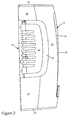
Figure 2 is a left side elevation view of the apparatus shown inFigure 1 ; -
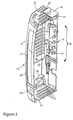
Figure 3 is a sectional view taken along lines III-III ofFigure 1 with the vaporizer and fan units removed; -
Figure 4 is a sectional view taken along lines IV-IV ofFigure 1 with the dispenser cover moved to an open position and the vaporizer and fan units removed; -
Figure 5 is a frontal isometric view of the preferred embodiment of apparatus according to the present invention with the dispenser cover located in an open position and the vaporizer remote to an operating position and the fan unit installed; -
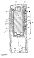
Figure 6 is a sectional view taken along lines VI-VI ofFigure 5 with the vaporizer and fan units installed according to the preferred embodiment of the present invention; -
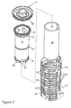
Figure 7 is an exploded isometric view of the vaporization unit according to the present invention; -
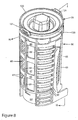
Figure 8 is an isometric view of the vaporization unit shown inFigure 7 in a preassembled state; -
Figure 9 is a sectional view taken along lines IX-IX ofFigure 8 and illustrating the arrangement of parts forming a vessel including one embodiment of an anti-spill structure for the volatile liquid in the vessel when placed in use; -
Figure 10 is a sectional view similar toFigure 9 and illustrating the arrangement of parts of the vaporizer in an operative state for dispensing volatile liquid; -
Figure 11 is an isometric view of the vessel including an anti-spill pad in place on the outer face surface of the vessel; -
Figure 12 is a detailed illustration of the anti-spill pad as shown inFigure 11 ; -
Figure 13 is a view similar toFigure 9 and illustrating the arrangement of parts forming a vessel including the preferred embodiment of an anti-spill structure for the volatile liquid in the vessel when placed in use; -
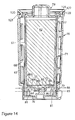
Figure 14 is a view of the vessel as shown infigure 13 when placed in use to dispense volatile liquid; -
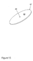
Figure 15 is an isometric view of a flow controller forming part of the vessel as shown inFigures 13 and14 ; -
Figure 16 is an isometric view illustrating the vessel and cap for supplying volatile fluid; -
Figures 17, 18 and 19 schematically illustrate the operational sequence of the locking barbs for installing the locking cap on the vessel; -
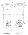
Figure 20 is an isometric view of an alternative embodiment of storage vessel for dispensing volatile liquid for the vaporizer according to the present invention; -
Figure 21 is an isometric view of a further alternative embodiment of storage vessel for dispensing volatile liquid for the vaporizer according to the present invention; -
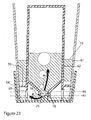
Figure 22 is a schematic illustration of the relation of parts during vaporization of volatile liquid according to the present invention; -
Figure 23 is a schematic illustration of the relation of parts during flow of volatile liquid into a storage cup pf the vaporizer according to the present invention; -
Figure 24 is an isometric illustration of a battery holder that is optionally added to the vaporizer for powering a motor driven fan; -
Figure 25 is an isometric illustration of the battery holder operatively seated in the housing for the motor driven fan; and -
Figure 26 is an isometric view illustrating the optional feature of a wrapper to control evaporation of the fluid. -
Figures 1- 6 illustrated the preferred embodiment of anaromatic dispenser apparatus 10 that includes according to the present invention adispenser cover 12 pivotally joined to adispenser frame 14 constructed to receive fasteners, not shown and well known in the art, to secure the an aromatic dispenser apparatus to vertical wall surface of the room or other structure. Thedispenser frame 14 is constructed to carry avaporizer 16 and, if desired, the option of a fan module 18 (Figure 5 ). - The
dispenser cover 12 is made up of acentral body 20 that is elongated and convexly shaped in the direction of the elongated length.Body sidewall sections central body 20 and define therewith a longitudinal cavity arranged to extend between top andbottom end walls Body sidewall sections apart walls walls central body 20 take the form of circular ring sector shaped walls that form part of the elongated convexly shaped central body. Vents 30 and 31 at opposite sides of the central body ventilate the interior of the dispenser cover.Vent 30 is bounded by an edge portion ofsidewall section 22 and by opposite sides bywalls 26 and 27.Vent 31 is bound along an edge portion ofsidewall section 23 and at opposite sides bywalls bottom end walls parallel slots curved slots 34 andterminal slots 35. The lengths of theparallel slots 32 in thetop wall 24 as compared with theparallel slots 33 in thebottom wall 25 are reduced to provide a cavity bounded by spacedparallel arms 36 extending in interior of the convexly shapedcentral body 20 where each arm contains an aperture 37 in the extended end portion terminating at ancurved end wall 38 forming a cam locking surface for pivotally mounting of thedispenser cover 12 to thedispenser frame 14. As shown inFigures 3 ,4 and5 when thedispenser cover 12 is pivoted to the operative position, i.e. seated against todispenser frame 14,parallel arms 39 with hooked ends extend parallel with the lengths of the bars from the interior of thecentral body 20 for locking engagement with resilient latch bars 39A extending from the lower portion of thedispenser frame 14 and terminating with lateral hooked ends. The resilient lock bars 39A are displaced from locked engagement with thearms 39 by spacedbars 39B on a key 39C. Appropriately, spaced openings in theend wall 25 pass thebars 39B into an engagement with free ends of the lock bars 39A and deflect the hooked ends of the bars from last engagement with the ends ofarms 39. - The
dispenser frame 14 takes the form of an elongated structure embodying a construction to form areceptacle section 40 terminating at a mountingfixture 41 for pivotal support of thedispenser cover 12 between the opened position shown inFigures 4 and5 and an operating position shown inFigures 1-3 . The mountingfixture 41 takes the form of arectangular block 42 contains ahinge pin 43 extending from each of the opposite lateral sides to extend into the aperture 37 in the extended end portion of thearms 36. The pivotal movement of the dispenser cover is controlled and limited by sliding contact between thecurved end walls 38 along pressure bearingplate sections 44 that serve to hold the cam-locking surface formed on the ends of thecurved end walls 38 for pivotally mounting of thedispenser cover 12 to thedispenser frame 14. Side guards 45 and 46 project from thereceptacle section 40 to traverse thevents dispenser cover 12 when in the operating position. The side guards 45 and 46 are bounded in a spaced relation by thesidewall extensions - The side guards have
apertures receptacle section 40 wherein thevaporizer 16 is fixedly positioned by upper and lower spaced pairs ofsupport hangers Figure 5 , the side guards 45 and 46 will overlie an evaporation chamber in thevaporizer 16 when mounted on the receptacle section for exposing the vents at the sides of thedispenser cover 12 to ventilate vapors from the evaporation chamber. - As shown in
Figure 6 , the interconnected relation between thevaporizer 16 and thereceptacle section 40 is controlled by a proprietary array arrangement ofkey apertures 49 formed in agrid plate section 50 of the vaporizer for a go/no go inter engaging relationship with a protruding array ofkeys 51 mounted in thereceptacle section 40. Underlying thereceptacle section 40 are parallel T-shapedapertures 52 for interlocking engagement with enlarged heads of latch bars 53 extending from adrive frame 54. The drive frame has a molded configuration with a cavity to receive amotor 55 for drivingfan blade assembly 56 mounted on the shaft of the motor to produce an air stream along the elongated convexly shaped central body of thedispenser cover 12. Thefan blade assembly 56 includes helically arrangedfan blades 57 extending from an annular sidewall of ahub 58. Thefan blades 57 are orientated on thehub 58 so as to create an up draft of air when driven by the motor. Guide bars 59 project from opposite lateral sides of thedispenser frame 14 to stabilize and guide thedispenser cover 12 during pivotal movement to the closed position. - The
vaporizer 16, as shown inFigures 6-10 , includesevaporation chamber 60 having an elongated tubular configuration and the side guards 45 and 46 as show inFigure 5 have concave configurations transverse to the extended length of the evaporation chamber to partly wrap in an outwardly spaced relation about the evaporation chamber and thereby maximize the exposure of the ambient air flow to the volatile liquid conducted by awick 61. The wick is generally rectangular shaped fibrous sheet of porous material fashioned into a cylinder without creases to reside in the evaporation chamber formed as a cylindrical cavity between avessel 62 containing the supply of volatile liquid and acylindrical ventilating housing 63 with aliquid storage cup 64 at one end forming a reservoir for volatile liquid dispensed from thevessel 62. Preferably, the wick has a keystone shape to produce the configuration of a truncated cone to extend generally parallel with the correspondingly truncated conical shape of both thevessel 62 and the ventilatedhousing 63. A portion of thewick 61 is immersed in volatile liquid in theliquid storage cup 64 while residing in the vaporization chamber. The shape of the ventilatinghousing 63 is comprised ofupright post members 65 extending from the rim of thecup 64 and dispersed about a circle defined by the rim of the cup. The rim of the cup is extended so as to prevent spillage of fluid from the interior of the cup. Thepost members 65 are interconnected bytransverse ribs 66 forming an elongated tubular venting cage extending between the side guards 45 and 46. Thepost members 65 interconnected by theribs 66 are arranged to provide that the cylindrical sidewall includesrectangular windows 66 for mounting the ventilating housing on thesupport hangers housing 63 includes parallel and radically outward extendingstabilizer bars 68 to engage with the receptacle section when mounting the vaporizer to the elongated frame. - As shown in
Figures 7-10 , the construction of the ventinghousing 63 produces anarray venting windows 69 confronting the elongated convexly shaped central body of thedispenser cover 12. Preferably, the sidewall of thevessel 62 or alternatively, thevessel 62 includes at least onewick support ring 70 in the vicinity of thecup 64 to maintain a desired spacing between of the wick from the confronting walls forming the evaporation chamber. Most desirably there are spaced apart rings protruding from a sidewall into the evaporation chamber for spacing the wick from the vessel. As shown inFigures 6 ,7 and9 three spaced apart rings 70, 71, and 72 from thevessel 62 protrude at varying heights with the greatest height located at the liquid discharge end of the vessel for spacing said wick from said vessel and stabilizing the wick in vaporization chamber. -
Figures 9-12 illustrate thevessel 62 incorporating one embodiment of ananti-spill sealing pad 73 the present invention. Theanti-spill sealing pad 73 has a generally rectangular shape, but preferably keystone shaped with tapering end walls, and dimensioned with a length sufficient to encircle the outer periphery of thevessel 62 immediately adjacent thesupport ring 70 at the liquid discharged end of thevessel 62. The width of thesealing pad 73 is selected so as to traverse the height of the bottom row of ventingwindows 69. As shown inFigure 12 , the sealing pad is preferably comprised of alayer 74a of elastic material such as expanded plastic, i.e. foamed plastic having a coating of an adhesive 74b on the opposed planar face surfaces to form an interconnected relation by adhering to the confronting surfaces of thevessel 62 and thewick 61. This interconnected relationship, as best shown inFigures 9 and10 is fortified by the thickness of the sealing pad being equal but preferably slightly greater than the width of the gap between the contact site on thevessel 22 andwick 61 near the liquid discharge end of the vessel. The resilient property of the layer ofelastic material 74a maintains the integrity of the interconnected relation and provide the desire anti-spill seal to avoid a flow of volatile liquid from the wick while immersed in a bath of volatile liquid incup 64. It will be understood by those skilled in the art that the function of thewick 61 is to broadcast the volatile liquid about the entire surface area of the wick counter concurrent to prevailing gravitational force. Thevaporizer 16 is placed in the operative position so that the major length of the wick remain parallel with the direction of gravity but in the event the vaporizer is place perpendicular to the operative position (horizontally) the liquid in the reservoir will propagate along the wick to such an extent that unwanted discharge may occur from the vaporizer. -
Figures 9 ,10 ,22 and23 illustrate atubular knife edge 75 projects in an upstanding manner from abottom wall 76 of thecup 64 for piercing a weakenend wall section 77 in a dispensingwall 78 having the form of a protruding sleeve section extending from theend wall 78A of thevessel 62 opposite avessel end cap 79, which is an optional alternative to an end wall integral with the side of the vessel. Preferably, thetubular knife edge 75 is traversed in the hollow of the tubular shape by anupstanding rib 76 in the liquid storage cup to support in a suspend fashion a fractured portion of the dispensing end wall produced by theknife edge 75 and residing in the vessel. Therib 76 angularly divides by traversing a portion of a cylinder internally to suspend a fractured part of the end wall. Ametering wall 80 takes the form of a downward annular extension of the side of thevessel 62. Themetering wall 80 is formed withopenings 81 dispersed about the terminal edge for counter concurrent flows of air and volatile fluid. As shown inFigures 9 ,10 ,13 ,22 and23 themetering wall 80 encircles the dispensingwall 78. Themetering wall 80 has at least one opening, for an intermittent flow of air into the gaseous impervious chamber formed within the vessel above the volume of volatile stored therein counter concurrent with a discharge of volatile fluid from the vessel to the liquid storage cup. The dispensingwall 78 extends to a dispensingplane 85 recessed from a normally submergedmetering plane 86 in the liquid contained in the storage cup. Preferably, themetering wall 80 includes a plurality ofopenings 81 extending in a direction proceeding from the normally submergedmetering plane 86 beyond the dispensingplane 85 for establishing the dispensing plane. As shown inFigures 22 and23 when the fluid level in thecup 64 is depleted by the operation of thewick 61 to a level below themetering plane 86openings 81 serve to control an intermittent flow of air by arrow A into the gaseous impervious chamber counter concurrent with a flow of volatile fluid by arrow F from the vessel to the liquid storage cup as shown inFigure 20 . - An alternative anti-spill function to that provided by the
sealing pad 73 is shown inFigures 13-15 . Aflow controller 87 is seated against the tubular sidewall of thevessel 62 in an overlying relation with thebottom wall 78A. As best shown inFigure 13 , thebottom wall 78A has a truncated conical shape with the conical truncation extending from the tubular side wall of the vessel and terminating at the dispensingwall 78. Theflow controller 87 is comprised of a disc shapedfibrous matt 88 that is formed with a diameter sufficiently large to form an upturnedannular rim 88A at the outer periphery when pressed into a tightly seating relation with the tubular side wall of thevessel 62, as shown inFigures 13 and14 . The arrangement is such that the truncated conical form of the bottom wall forms a fluid flow path for liquid emerging from the underside of thefibrous matt 88 after wicking through the fibrous material of the matt and directs the fluid flow to the dispensingwall 78 where acentral aperture 89 directly overlies the dispensingwall 78 and supplies a stream of fluid to the dispensing wall. The diameter of theaperture 89 is of the order of a small orifice so as to provide a valve metering function that prevents an unwanted surge flow through the dispensing wall in the event, for example, the vaporizer is placed in a non-operative horizontal orientation whereby fluid flow is greatly diminished as a result of the metering function of theaperture 89 as well as the wicking of fluid. The existence of theaperture 98 is preferred but can be eliminated when the fluid can permeate the fibrous matt at a rate that supplies sufficient fluid for the wicking process by thewick 61. The fibrous matt can take the form of a liquid permeable non-woven fiber such as paper, felt or the like. In the operation of the embodiment of thevessel 62 containing theflow controller 87, the fibrous nature of the disc allows wicking of fluid in combination with fluid flow from theaperture 89 through the dispensing wall and into thecup 64. - As shown in
Figure 7 and16-19 the provision of a flangedvessel end cap 79 allows the access to a liquid storage compartment of thevessel 62 for the introduction of the volatile liquid into the vessel and forms an airtight seal with the vessel. The vessel end cap hasthreads 90 that engage withmating threads 91 on arim portion 92 of the vessel. To prevent unwanted access to the storage chamber in the vessel, unthreading of the vessel end cap is prevented by the provision ofupstanding barbs 93 at spaced intervals along thescrew threads 90 corresponding to intervals ofupstanding barbs 94 along themating screw thread 91 on annular side wall formed by therim portion 92. The operation of the cap moved into a locked vacuum tight condition on the vessel is diagrammatically illustrated byFigures 17-19 . As shown inFigure 17 projecting from thethreads 90 on the cap are thebarbs 93 and the threaded relationship with thethreads 91 on the vessel operate to move thebarb 94 into a confronting relationship withbarbs 92.Figure 18 illustrates that travel of thethreads 90 along thethreads 91 cause thebarbs 93 to collide with thebarbs 94 and deform due to the elasticity of the plastic material forming the vessel and the vessel cap. The deformation eventually gives way to the passage of the barbs beyond the collision site. As shown inFigure 19 , after thebarbs - In the embodiments of the vessel according to the present invention shown in
Figures 20 and 21 , a flangedtop end wall 96 of thevessels sidewall 100 to provide the gaseous impervious chamber above a stored volume of volatile liquid in each of the vessels. The protruding sleeve section 101 of thevessel 97 shown inFigure 17 is provided withinternal threads 102 to receiveexternal threads 103 on aclosure cap 104 containing a pierceable sealed film ormembrane 105 from which there projects ametering wall 106 comprise of a half divided tube segment forming a protruding semicircular guard wall. The protrudingsleeve section 107 of thevessel 98 shown inFigure 21 is provided withexternal threads 108 to receive internal threads in arim 109 of aclosure cap 110 containing a pierceable sealed film ormembrane 111. The sidewall of the vessel is continued by the projectingmetering wall 80 having the opening 81 dispersed about the terminal edge for counter concurrent flows of air and volatile liquid as described herein above. - As shown in
Figures 8 ,9 and10 , the ventilatinghousing 63 further includessnap ring segments 120 to engage and release each of the cavities located in aflanged portion 124 of theend cap 79 of thevessel 62 andtop walls 96 at the end of thevessels snap ring segments 120 fixedly position the metering wall at the dispensing end of the vessel at a predetermined spacing from floor of theliquid storage cup 64. Diametrically opposedtear segments 121 are between snap ring segments120. Thetear segments 121 are joined to the snap ring segments by weakened walls that are easily fractured for removal to allow flexing of the snap ring segments when positioning the flanged end of the vessel between said snap ring segments. Thesnap ring segments 120 include a truncatedconical support surface 122 that receives in a confronting relation a mating truncatedconical surface 123 formed on the flanged portion of the end caps 79 andtop wall 96 for suspending the vessel in the evaporation chamber. The vaporizer of the present invention is quickly replaced by removing theflange portion 124 of thecap 122 from thesnap ring segment 120 and then inserting a replacement vaporizer by inserting theflange 124 in the snap ring segments as described herein above. The typical time for a total vaporization of the fluid in a newly installed vaporizer is 60 days with passive airflow and typically 30 days with a forced airflow by the fan assembly. - When it is desired to artificially induce an air flow in the dispenser cover, as shown in
Figures 5 ,24 and 25 , a battery storage compartment is formed byopposed end walls 130 confronting pole pieces of a battery when seated against acylindrical battery 131container wall 132 terminating at spaced apartsuspension arms 133 for support by thevaporizer 16.Strips 134 of electrically conductive material extending from thedrive frame 54 toward theend walls 130 for contact with pole pieces of a battery when stored in abattery container wall 132. The electricallyconductive strips 134 are retained byupstanding arms 135 spaced apart sufficiently to receive the end walls of the battery storage compartment. Theend walls 130 of the battery storage compartment are arranged to expose the pole pieces of a battery while traversing opposite ends thereof. Theupstanding arms 135 comprise a rectangular bar traversing one end of the battery compartment and a rectangular bar containing a centrally locatedindexing protuberance 136 to receive and uniquely define the location of a positive pole piece of a battery when located in the battery storage compartment. Thedrive frame 54 includes ridge aligned with one of the electrically conductive strips for passage into theindexing protuberance 136 to allow electrical connection between pole pieces of the battery and the electrically conductive strips. If desired, the battery may be eliminated and a step down transformer with an AC to DC rectifier can be direct connected to the fan motor. - As shown in
Figure 26 there is shown the optional feature of providing awrapper 200 constructed of a sheet of heat shrinkable plastic material fashioned into a tubular shape that can be passed over the vaporizer to substantially completely envelope the outer cylindrical surface. Thewrapper 200 stops short to allow exposure of the radically outward extending stabilizer bars 68. The wrapper is formed with diametrically opposedvertical perforations 201 and a perforation 202 encircling the mid portion of the tubular shape. Theperforations 201 and 202 are used for controlling the extent to which ambient air can infiltrate the evaporation chamber. More particularly, severing thewrapper 200 along perforation 202 allows removal of an upper half of the wrapper from the ventilatinghousing 63 of the vaporizer thus avoiding exposure of ambient air to the entire height of the evaporation chamber. The use of the wrapper serves to throttle back the speed of dispensing of the volatile liquid. Severing the wrapper alongperforation 201 allows removal of the entire wrapper from the vaporizer thus exposure of ambient air to the entire height of the evaporation chamber and thus serves to maximizing the speed of dispensing of the volatile liquid. - While the present invention has been described in connection with the preferred embodiments of the various figures, it is to be understood that other similar embodiments may be used or modifications and additions may be made to the described embodiment for performing the same function of the present invention without deviating there from. Therefore, the present invention should not be limited to any single embodiment, but rather construed in breadth and scope in accordance with the recitation of the appended claims.
Claims (24)
- A vaporizer for an aromatic odor neutralizer, said vaporizer including the combination of:a vessel including a side wall joined with a first end wall to form a gaseous impervious chamber above a stored volume of volatile liquid bounded by a dispensing wall opposite said first end wall;a ventilating housing including a cylindrical side wall for receiving said vessel to form a vaporization chamber there between terminating at a liquid storage cup for volatile liquid dispensed from said vessel;a metering wall encircling said dispensing wall, said metering wall having at least one opening for an intermittent flow of air into said gaseous impervious chamber counter concurrent with a discharge of volatile fluid from said vessel to said liquid storage cup;an upstanding surface in said liquid storage cup for piercing said dispensing end wall; anda wick having a portion immersed in volatile liquid in said liquid storage cup while residing in said vaporization chamber.
- The vaporizer according to claim 1 wherein said wick is cylindrical without creases when residing in said vaporization chamber.
- The vaporizer according to claim 1 wherein said sidewall includes a protruding support for spacing said wick from said vessel in said vaporization chamber.
- The vaporizer according to claim 1 wherein said sidewall includes spaced apart rings protruding from said sidewall for spacing said wick from said vessel in said vaporization chamber.
- The vaporizer according to claim 1 wherein said ventilating housing further includes a snap ring to engage and release said first end of said vessel for fixedly positioning said dispensing end wall at a predetermined spacing from said liquid storage cup.
- The vaporizer according to claim 1 wherein said ventilating housing further includes diametrically opposed tear segments between snap ring segments, said tear segments being removable to allow flexing of said snap ring segments when positioning said first end of said vessel between said snap ring segments for fixedly positioning said dispensing end wall at a predetermined spacing from said liquid storage cup.
- The vaporizer according to claim 1 wherein said first end of said vessel includes a cap having a screw thread containing upstanding barbs at spaced intervals corresponding to intervals of upstanding barbs along a mating screw thread on said annular side wall to allow access to liquid storage compartment of the vessel and form an airtight and non reversible seal with said side wall of said vessel body.
- The vaporizer according to claim 1 wherein said first end wall of said vessel is integrally formed with said side wall to provide said gaseous impervious chamber above a stored volume of volatile liquid, and wherein said dispensing wall includes a collar having a screw threaded side wall remote to said gaseous impervious chamber for receiving closure cap having a membrane peaceable by said upstanding surface.
- The vaporizer according to claim 1 wherein said screw threaded sidewall is internal of said collar and said closure cap includes an externally threaded section terminating at a protruding semicircular guard wall.
- The vaporizer according to claim 1 wherein said upstanding surface in said liquid storage cup includes a rib to suspend a fractured portion of said dispensing end wall in said vessel.
- The vaporizer according to claim 1 wherein said upstanding surface in said liquid storage cup includes an angularly dived portion of a cylinder traversed internally by a rib to suspend a fractured portion of said dispensing end wall in said vessel.
- The vaporizer according to claim 1 wherein said dispensing wall extends to a dispensing plane recessed from a normally submerged plane in liquid contained in said storage cup, and wherein said metering wall includes a plurality of openings extend in a direction proceeding from said normally submerged plane beyond said dispensing plane for establishing said dispensing plane to control an intermittent flow of air into said gaseous impervious chamber counter concurrent with a flow of volatile fluid from said vessel to said liquid storage cup.
- The vaporizer according to claim 1 further including a dispenser cover supported by an elongated frame including a receptacle section and wherein said cylindrical sidewall includes rectangular windows for mounting said ventilating housing on said receptacle section.
- The vaporizer according to claim 1 further including a sheathing supported by said ventilating housing for selectively controlling the evaporation of volatile liquid from said vaporizer.
- The vaporizer according to claim 1 further comprising an anti-spill seal at said liquid storage cup between said vessel and said wick.
- The vaporizer according to claim 15 wherein said anti-spill seal includes elastic material with adhesive on opposed planar face surfaces to adhere with confronting surfaces of said vessel and wick.
- The vaporizer according to claim 1 further comprising a fluid permeable disc seated against said side wall of said vessel in an overlying relation with said dispensing wall for delivering said volatile liquid to said liquid storage cup.
- The vaporizer according to claim 17 wherein said fluid permeable disc comprises a fibrous matt with a diameter sufficiently large to form an upturned annular rim at the outer periphery for forming a tightly seating relation with said side wall of said vessel.
- The vaporizer according to claim 17 wherein said fluid permeable disc includes an orifice for metering fluid flow to said dispensing wall.
- The vaporizer according to claim 17 wherein said vessel includes a bottom wall having a truncated conical shape with the conical truncation extending from said side wall of said vessel and terminating at said dispensing wall for forming a fluid flow path for fluid permeating said disc.
- The aromatic dispenser apparatus according to claim 1 wherein each of said ventilating housing and said vessel include confronting truncated conical support surfaces for suspending said vessel in said evaporation chamber.
- The aromatic dispenser apparatus according to claim 1 wherein said ventilating housing further includes a peripheral sidewall integral with a bottom wall forming a reservoir to maintain a supplying said volatile liquid for said evaporation chamber.
- The aromatic dispenser apparatus according to claim 22 wherein said peripheral sidewall includes parallel and radically outward extending stabilizer bars for mounting said ventilating housing.
- The aromatic dispenser apparatus according to claim 23 wherein said peripheral sidewall includes an elongated tubular venting cage extending between said side guards.
Applications Claiming Priority (3)
| Application Number | Priority Date | Filing Date | Title |
|---|---|---|---|
| US11/805,662 US7857236B2 (en) | 2007-05-24 | 2007-05-24 | Apparatus for dispensing an aromatic odor neutralizer |
| US11/999,763 US8005350B2 (en) | 2007-05-24 | 2007-12-08 | Gravity driven fluid supply vessel for dispensing an aromatic odor neutralizer |
| US12/153,063 US7922104B2 (en) | 2007-05-24 | 2008-05-13 | Gravity driven fluid supply vessel for dispensing an aromatic odor neutralizer |
Publications (1)
| Publication Number | Publication Date |
|---|---|
| EP1997518A1 true EP1997518A1 (en) | 2008-12-03 |
Family
ID=39619369
Family Applications (2)
| Application Number | Title | Priority Date | Filing Date |
|---|---|---|---|
| EP08156747A Withdrawn EP1997519A1 (en) | 2007-05-24 | 2008-05-22 | An aromatic dispenser apparatus |
| EP08156746A Withdrawn EP1997518A1 (en) | 2007-05-24 | 2008-05-22 | Gravity driven fluid supply vessel for dispensing an aromatic odor neutralizer |
Family Applications Before (1)
| Application Number | Title | Priority Date | Filing Date |
|---|---|---|---|
| EP08156747A Withdrawn EP1997519A1 (en) | 2007-05-24 | 2008-05-22 | An aromatic dispenser apparatus |
Country Status (4)
| Country | Link |
|---|---|
| US (1) | US7922104B2 (en) |
| EP (2) | EP1997519A1 (en) |
| CA (2) | CA2663719C (en) |
| MX (1) | MX2008006570A (en) |
Cited By (3)
| Publication number | Priority date | Publication date | Assignee | Title |
|---|---|---|---|---|
| EP3117841A1 (en) * | 2015-07-16 | 2017-01-18 | Eurvest | Autonomously powered vapour release device |
| EP2429844B1 (en) * | 2009-05-12 | 2020-03-25 | The Procter and Gamble Company | Dispenser for volatile compositions |
| EP3650051A3 (en) * | 2018-10-21 | 2020-08-19 | San Jamar, Inc. | Passive fragrance dispenser system |
Families Citing this family (25)
| Publication number | Priority date | Publication date | Assignee | Title |
|---|---|---|---|---|
| US8469293B2 (en) * | 2010-04-16 | 2013-06-25 | Richard L. Doty | Digital odor generator |
| AU2012223382B2 (en) | 2011-03-01 | 2014-05-29 | S. C. Johnson & Son, Inc. | Drive module assembly and method of assembling same |
| USD667097S1 (en) * | 2011-09-26 | 2012-09-11 | Fellowes, Inc. | Air purifier |
| USD664248S1 (en) * | 2012-02-06 | 2012-07-24 | Hung Hsing Electric Co., Ltd. | Vertically-oriented air purifying and humidifying apparatus |
| US9663932B2 (en) | 2012-10-29 | 2017-05-30 | Xela Innovations, Llc | Fixture cleaning and deodorizing apparatus and method of use |
| US9453330B2 (en) | 2012-10-29 | 2016-09-27 | Xela Innovations, Llc | Fixture cleaning and deodorizing apparatus and method of use |
| US8889082B2 (en) * | 2013-03-15 | 2014-11-18 | San Jamar, Inc. | Apparatus for metered dose of odor control substance |
| DE202014005446U1 (en) * | 2014-07-04 | 2015-10-06 | Cws-Boco Supply Ag | Device for generating a fragrance-laden fluid stream |
| USD843555S1 (en) * | 2015-10-19 | 2019-03-19 | F-Matic, Inc. | Base of a fragrance dispenser |
| PL3472093T3 (en) * | 2016-06-20 | 2024-04-22 | Fragrance Delivery Technologies Private Limited | VOLATILE LIQUID DOSING SYSTEM |
| EP3562519B1 (en) * | 2016-12-29 | 2025-09-17 | Scent Experience, S.L.U. | Perfume testers |
| USD829302S1 (en) * | 2017-07-18 | 2018-09-25 | Dynamic Solutions Worldwide, LLC | Plug in insect trap |
| USD834135S1 (en) * | 2017-08-17 | 2018-11-20 | Da Vinci Ii Csj, Llc. | Repellent assembly |
| USD912794S1 (en) | 2018-08-01 | 2021-03-09 | Fresh Products, Inc. | Air freshener |
| USD900291S1 (en) | 2018-08-06 | 2020-10-27 | Fresh Products, Inc. | Air freshener |
| US11000621B2 (en) * | 2019-02-25 | 2021-05-11 | Majestic-M&A International Co., Ltd. | Siphon type essence diffuser having block-preventing and leakage-preventing capabilities |
| US11369710B2 (en) | 2019-05-16 | 2022-06-28 | Dispensing Dynamics International, Inc. | Fragrance dispensers and methods |
| ES2818748B2 (en) * | 2019-10-09 | 2022-03-22 | Zobele Espana Sa | Volatile substance diffusion device |
| USD936195S1 (en) | 2019-10-25 | 2021-11-16 | Xela Innovations, Llc | Dispenser |
| EP4048126A1 (en) | 2019-10-25 | 2022-08-31 | Xela Innovations, LLC | Dispenser for use with refill cartridge |
| US12458722B1 (en) | 2020-02-27 | 2025-11-04 | Fresh Products, Inc. | Systems, method, and devices for dispensing volatile liquids |
| CN111450295B (en) * | 2020-04-16 | 2021-04-20 | 广州丹绮环保科技有限公司 | Self-volatilization fragrance-expanding machine |
| US12096803B2 (en) * | 2020-11-04 | 2024-09-24 | Anthony Hamilton | E-cigarette vaporizer cartridge filling device |
| USD1040553S1 (en) | 2021-11-15 | 2024-09-03 | Xela Innovations, Llc | Dispenser |
| FR3129086B1 (en) * | 2021-11-17 | 2025-03-28 | Caelimp | Diffusing device intended to disperse in the air, in the vapor state, a substance in the liquid or solid state at room temperature |
Citations (9)
| Publication number | Priority date | Publication date | Assignee | Title |
|---|---|---|---|---|
| EP0078114A1 (en) * | 1981-10-26 | 1983-05-04 | KAUFMAN, John George | Liquid feed device |
| US5238187A (en) * | 1991-10-07 | 1993-08-24 | Surco Products, Inc. | Liquid vaporizing, diffusing and dripping |
| US5533705A (en) | 1995-01-09 | 1996-07-09 | Pestco, Inc. | Drive for deodorant apparatus |
| US5810253A (en) * | 1995-07-24 | 1998-09-22 | Ohayon; Nissim | Device for the controlled dispensation and evaporation of volatile liquids |
| US5816845A (en) | 1994-09-12 | 1998-10-06 | Sumitomo Wiring Systems, Ltd. | Connector for flat cable |
| US6553712B1 (en) * | 1999-07-01 | 2003-04-29 | S. C. Johnson & Son, Inc. | Insecticidal liquid bait station |
| US6957779B2 (en) | 2001-11-20 | 2005-10-25 | Microlin, L.C. | Foldable, refillable, sustained-release fluid delivery system |
| WO2006087564A1 (en) * | 2005-02-16 | 2006-08-24 | Aroma Cair Ltd | A dispensing apparatus |
| US20070001024A1 (en) * | 1997-06-20 | 2007-01-04 | Microlin, L.C. | Device employing gas generating cell for facilitating controlled release of fluid into ambient environment |
Family Cites Families (6)
| Publication number | Priority date | Publication date | Assignee | Title |
|---|---|---|---|---|
| FR2586353B1 (en) * | 1985-08-21 | 1988-10-14 | Brun Michel | ODORIFYING VOLATILE SUBSTANCE DIFFUSER WITH ADJUSTABLE EMISSION FOR MOTOR VEHICLE |
| US5328646A (en) * | 1993-10-15 | 1994-07-12 | Vaportek, Inc. | Air flow control system with replaceable cartridge |
| US6503459B1 (en) * | 1999-06-17 | 2003-01-07 | S.C. Johnson & Son, Inc. | Heated volatile dispenser |
| US7167641B2 (en) * | 2002-06-06 | 2007-01-23 | S.C. Johnson & Son, Inc. | Localized surface volatilization |
| CN1820543B (en) * | 2003-02-07 | 2010-11-17 | 约翰逊父子公司 | Diffuser with led nightlight |
| US6938883B2 (en) * | 2003-06-27 | 2005-09-06 | S.C. Johnson & Son, Inc. | Guide for selectively receiving a wick in a dispenser for a volatile liquid |
-
2008
- 2008-05-13 US US12/153,063 patent/US7922104B2/en not_active Expired - Fee Related
- 2008-05-21 MX MX2008006570A patent/MX2008006570A/en not_active Application Discontinuation
- 2008-05-22 CA CA2663719A patent/CA2663719C/en not_active Expired - Fee Related
- 2008-05-22 EP EP08156747A patent/EP1997519A1/en not_active Withdrawn
- 2008-05-22 CA CA002631922A patent/CA2631922C/en not_active Expired - Fee Related
- 2008-05-22 EP EP08156746A patent/EP1997518A1/en not_active Withdrawn
Patent Citations (10)
| Publication number | Priority date | Publication date | Assignee | Title |
|---|---|---|---|---|
| EP0078114A1 (en) * | 1981-10-26 | 1983-05-04 | KAUFMAN, John George | Liquid feed device |
| US5238187A (en) * | 1991-10-07 | 1993-08-24 | Surco Products, Inc. | Liquid vaporizing, diffusing and dripping |
| US5816845A (en) | 1994-09-12 | 1998-10-06 | Sumitomo Wiring Systems, Ltd. | Connector for flat cable |
| US5533705A (en) | 1995-01-09 | 1996-07-09 | Pestco, Inc. | Drive for deodorant apparatus |
| US6105916A (en) | 1995-01-09 | 2000-08-22 | Pestco, Inc. | Frame assembly for deodorant cabinet |
| US5810253A (en) * | 1995-07-24 | 1998-09-22 | Ohayon; Nissim | Device for the controlled dispensation and evaporation of volatile liquids |
| US20070001024A1 (en) * | 1997-06-20 | 2007-01-04 | Microlin, L.C. | Device employing gas generating cell for facilitating controlled release of fluid into ambient environment |
| US6553712B1 (en) * | 1999-07-01 | 2003-04-29 | S. C. Johnson & Son, Inc. | Insecticidal liquid bait station |
| US6957779B2 (en) | 2001-11-20 | 2005-10-25 | Microlin, L.C. | Foldable, refillable, sustained-release fluid delivery system |
| WO2006087564A1 (en) * | 2005-02-16 | 2006-08-24 | Aroma Cair Ltd | A dispensing apparatus |
Cited By (3)
| Publication number | Priority date | Publication date | Assignee | Title |
|---|---|---|---|---|
| EP2429844B1 (en) * | 2009-05-12 | 2020-03-25 | The Procter and Gamble Company | Dispenser for volatile compositions |
| EP3117841A1 (en) * | 2015-07-16 | 2017-01-18 | Eurvest | Autonomously powered vapour release device |
| EP3650051A3 (en) * | 2018-10-21 | 2020-08-19 | San Jamar, Inc. | Passive fragrance dispenser system |
Also Published As
| Publication number | Publication date |
|---|---|
| US20080290186A1 (en) | 2008-11-27 |
| CA2663719A1 (en) | 2008-11-24 |
| MX2008006570A (en) | 2009-03-04 |
| EP1997519A1 (en) | 2008-12-03 |
| CA2663719C (en) | 2010-03-23 |
| CA2631922C (en) | 2009-12-22 |
| CA2631922A1 (en) | 2008-11-24 |
| US7922104B2 (en) | 2011-04-12 |
Similar Documents
| Publication | Publication Date | Title |
|---|---|---|
| CA2663719C (en) | Gravity driven fluid supply vessel for dispensing an aromatic odor neutralizer | |
| US8005350B2 (en) | Gravity driven fluid supply vessel for dispensing an aromatic odor neutralizer | |
| US7857236B2 (en) | Apparatus for dispensing an aromatic odor neutralizer | |
| EP1808185B1 (en) | Guide for selectively receiving a wick in a dispenser for a volatile liquid | |
| US6957779B2 (en) | Foldable, refillable, sustained-release fluid delivery system | |
| CA2526874C (en) | Apparatus for emitting a chemical agent | |
| US5147582A (en) | Turbo air freshener | |
| US4294778A (en) | Evaporative dispenser | |
| CN104220176B (en) | Atomiser system | |
| TWI445498B (en) | Air supply type drug diffusion device using fuel cell as power source | |
| ES2293593T3 (en) | ELECTROMECHANICAL DEVICE FOR DISPENSING VOLATILE SUBSTANCES WITH A SINGLE DISPENSATION MECHANISM AND CONTAINER CARTRIDGE WITH MULTIPLE RECEPTACLES. | |
| CN104640574A (en) | Centrifugal fan device | |
| US10307502B2 (en) | Spill-resistant air freshener canister | |
| JP3904393B2 (en) | Controlled release of substances | |
| EP0019626B1 (en) | Evaporative dispenser | |
| EP1252899B1 (en) | Dispenser of airborne substances | |
| CN1798585B (en) | Device for emitting chemical agents | |
| JP2004230167A (en) | Mechanical container | |
| EP0431742B1 (en) | Turbo-air freshener | |
| US20050263609A1 (en) | Foldable, refillable, sustained-release fluid delivery system | |
| US20190240367A1 (en) | Spill-proof, passive air freshener refill cartridge | |
| US12343457B2 (en) | Device for diffusing volatile substances | |
| RS64848B1 (en) | Volatile liquid dispensing system | |
| HK40113744A (en) | Diffuser device for dispersing a substance that is in the liquid or solid state at room temperature into the air as vapor | |
| KR20100045202A (en) | Chemical dispenser |
Legal Events
| Date | Code | Title | Description |
|---|---|---|---|
| PUAI | Public reference made under article 153(3) epc to a published international application that has entered the european phase |
Free format text: ORIGINAL CODE: 0009012 |
|
| AK | Designated contracting states |
Kind code of ref document: A1 Designated state(s): AT BE BG CH CY CZ DE DK EE ES FI FR GB GR HR HU IE IS IT LI LT LU LV MC MT NL NO PL PT RO SE SI SK TR |
|
| AX | Request for extension of the european patent |
Extension state: AL BA MK RS |
|
| 17P | Request for examination filed |
Effective date: 20090508 |
|
| 17Q | First examination report despatched |
Effective date: 20090612 |
|
| AKX | Designation fees paid |
Designated state(s): AT BE BG CH CY CZ DE DK EE ES FI FR GB GR HR HU IE IS IT LI LT LU LV MC MT NL NO PL PT RO SE SI SK TR |
|
| STAA | Information on the status of an ep patent application or granted ep patent |
Free format text: STATUS: THE APPLICATION IS DEEMED TO BE WITHDRAWN |
|
| 18D | Application deemed to be withdrawn |
Effective date: 20091223 |