EP1997423B1 - Operation microscope with illumination device - Google Patents
Operation microscope with illumination device Download PDFInfo
- Publication number
- EP1997423B1 EP1997423B1 EP08156255A EP08156255A EP1997423B1 EP 1997423 B1 EP1997423 B1 EP 1997423B1 EP 08156255 A EP08156255 A EP 08156255A EP 08156255 A EP08156255 A EP 08156255A EP 1997423 B1 EP1997423 B1 EP 1997423B1
- Authority
- EP
- European Patent Office
- Prior art keywords
- illumination
- beam path
- surgical microscope
- light
- microscope according
- Prior art date
- Legal status (The legal status is an assumption and is not a legal conclusion. Google has not performed a legal analysis and makes no representation as to the accuracy of the status listed.)
- Active
Links
Images


Classifications
-
- G—PHYSICS
- G02—OPTICS
- G02B—OPTICAL ELEMENTS, SYSTEMS OR APPARATUS
- G02B21/00—Microscopes
- G02B21/06—Means for illuminating specimens
- G02B21/08—Condensers
- G02B21/082—Condensers for incident illumination only
-
- A—HUMAN NECESSITIES
- A61—MEDICAL OR VETERINARY SCIENCE; HYGIENE
- A61B—DIAGNOSIS; SURGERY; IDENTIFICATION
- A61B3/00—Apparatus for testing the eyes; Instruments for examining the eyes
- A61B3/10—Objective types, i.e. instruments for examining the eyes independent of the patients' perceptions or reactions
- A61B3/13—Ophthalmic microscopes
- A61B3/135—Slit-lamp microscopes
-
- G—PHYSICS
- G02—OPTICS
- G02B—OPTICAL ELEMENTS, SYSTEMS OR APPARATUS
- G02B21/00—Microscopes
- G02B21/0004—Microscopes specially adapted for specific applications
- G02B21/0012—Surgical microscopes
-
- G—PHYSICS
- G02—OPTICS
- G02B—OPTICAL ELEMENTS, SYSTEMS OR APPARATUS
- G02B21/00—Microscopes
- G02B21/18—Arrangements with more than one light path, e.g. for comparing two specimens
- G02B21/20—Binocular arrangements
- G02B21/22—Stereoscopic arrangements
-
- A—HUMAN NECESSITIES
- A61—MEDICAL OR VETERINARY SCIENCE; HYGIENE
- A61B—DIAGNOSIS; SURGERY; IDENTIFICATION
- A61B90/00—Instruments, implements or accessories specially adapted for surgery or diagnosis and not covered by any of the groups A61B1/00 - A61B50/00, e.g. for luxation treatment or for protecting wound edges
- A61B90/20—Surgical microscopes characterised by non-optical aspects
-
- A—HUMAN NECESSITIES
- A61—MEDICAL OR VETERINARY SCIENCE; HYGIENE
- A61B—DIAGNOSIS; SURGERY; IDENTIFICATION
- A61B90/00—Instruments, implements or accessories specially adapted for surgery or diagnosis and not covered by any of the groups A61B1/00 - A61B50/00, e.g. for luxation treatment or for protecting wound edges
- A61B90/30—Devices for illuminating a surgical field, the devices having an interrelation with other surgical devices or with a surgical procedure
-
- A—HUMAN NECESSITIES
- A61—MEDICAL OR VETERINARY SCIENCE; HYGIENE
- A61F—FILTERS IMPLANTABLE INTO BLOOD VESSELS; PROSTHESES; DEVICES PROVIDING PATENCY TO, OR PREVENTING COLLAPSING OF, TUBULAR STRUCTURES OF THE BODY, e.g. STENTS; ORTHOPAEDIC, NURSING OR CONTRACEPTIVE DEVICES; FOMENTATION; TREATMENT OR PROTECTION OF EYES OR EARS; BANDAGES, DRESSINGS OR ABSORBENT PADS; FIRST-AID KITS
- A61F9/00—Methods or devices for treatment of the eyes; Devices for putting-in contact lenses; Devices to correct squinting; Apparatus to guide the blind; Protective devices for the eyes, carried on the body or in the hand
- A61F9/007—Methods or devices for eye surgery
Definitions
- the invention relates to a surgical microscope with an illumination device which can provide illumination light for the object region with a first illumination beam path and with a second illumination beam path, a first light emission unit being provided for providing light in the first illumination beam path and a field diaphragm being arranged in the second illumination beam path. and wherein the first illumination beam path has an illumination optical system which images the light exit plane of the first light exit unit or a plane conjugate to this light exit plane into a first image plane.
- a surgical microscope of the type mentioned is from the DE 40 28 605 C2 known.
- This surgical microscope contains a lighting device in which illumination light is provided over the exit end of a light guide perpendicular to the optical axis of the microscope main objective.
- illumination light is deflected toward the microscope main objective with a beam path which is parallel to the optical axis of the microscope main objective.
- the illumination light is thus guided with a first beam path through the microscope main objective to the object area, which is close to the axis of the optical axes of the observation beam paths of the microscope, and with a second beam path, which illuminates the object area with obliquely and a distant axis with respect to the optical Has axes of observation beam paths of the surgical microscope.
- the luminous field corresponds to the image produced by the illumination optics of a arranged at the exit end of the light guide field stop in the object area.
- an illumination device for an ophthalmic surgical microscope which has an illumination beam path, which causes an image of the illumination pupil of the illumination device on the retina of an examined patient's eye.
- the DE 10 2004 050 651 A1 discloses a surgical microscope with an illumination device in which a beam splitter element is provided in the stereoscopic observation beam paths in order to coaxially superimpose illumination illumination light onto the observation beam paths, which light beam is directed to the object region by the microscope main objective.
- a surgical microscope with a lighting device that provides illumination light with an illumination beam path that is guided through the microscope main objective to the object area.
- the illumination device comprises a Köhler illumination optics.
- a reflex diaphragm is arranged in the illumination beam path. The reflex diaphragm causes a shading of such illumination light, which would reach the observation beam paths of the surgical microscope due to reflections on the microscope main objective. In this way disturbing reflexes in the observation image of the surgical microscope can be avoided.
- an ophthalmic surgical microscope with a lighting device which includes a one in the illumination beam path and swing out Retinaschutzblende.
- the Retinatikblende is designed as an annular aperture. In the pivoted state, it is located in a plane conjugate to the object plane of the surgical microscope and blocks illumination light or attenuates such illumination light, which otherwise can pass through the iris of a patient's eye onto its retina.
- a surgical microscope that includes a lighting device that makes it possible to illuminate the object area in different configurations for illumination light.
- the illumination device can on the one hand provide illumination light via a field diaphragm, which is imaged by the microscope main objective into the object region.
- the illumination device can illuminate the object area with illumination light in a configuration in which the incandescent filament of a lamp or the outlet end of a light guide is imaged by the microscope main objective into the object area.
- the DE 20 2004 019 849 U1 discloses a surgical microscope that allows illumination of an object area with differently configured illuminating light through the microscope main objective.
- a first configuration for illumination light is according to the DE 43 44 770 A1 imaged via the microscope main objective a field diaphragm in the object area.
- the illumination light according to the second configuration passes through a diffuser disposed at a light source which is imaged in the object area.
- the DE 196 11 044 A1 discloses a surgical microscope with a light source; a first illumination optical system for projecting light from the light source onto an eye to be examined from a first direction and a second illumination optical system for projecting light from the light source onto the eye to be examined Eye out of one direction, different from the first direction; and an observation optical system for thereby viewing the eye to be examined illuminated by at least one of the first illumination optical system and the second illumination optical system.
- the EP 1 109 046 A1 discloses an illumination device for a surgical microscope, with which the illumination takes place through the microscope objective.
- the angle of the incident light with the optical axis of the microscope objective and also the intensity of the various light beams can be changed independently of each other with the aid of two independently movable reflection elements.
- the object of the invention is to provide a surgical microscope which is suitable for use in ophthalmology and makes it possible to visualize transparent structures in the anterior section of a patient's eye with good contrast.
- This object is achieved by a surgical microscope of the type mentioned above, in which an illumination optical unit is provided in the second illumination beam path, which images the field diaphragm into a second image plane different from the first image plane.
- the first illumination beam path is moved relative to at least one optical axis of the observation beam path of the surgical microscope with a course close to the axis to the object region. In this way, a red reflex with good homogeneity can be generated on a patient's eye.
- the second illumination beam path is guided relative to at least one optical axis of the surgical microscope with an off-axis course to the object area. In this way, a good plasticity of an image of the object area is effected in the surgical microscope, since the obliquely incident illumination light causes structures in the object area shadowing.
- the second image plane in which the image of the field stop lies in the second illumination beam path, coincides with or lies in the vicinity of the object plane of the surgical microscope. In this way, a clean limitation of the light field in the object area is effected.
- a surgical microscope is created in this way, in which a large light field is guaranteed with clean boundary and in which at the same time a bright red reflex can be generated on a patient's eye examined.
- the first illumination beam path and / or the second illumination beam path penetrate the microscope main objective. In this way, a large free working area between the microscope main objective and the object area is made possible.
- a first or a second deflection element is provided in the surgical microscope, which directs near-axis or off-axis illumination light through the microscope main objective to the object area. In this way, a lateral coupling of illumination light into the system with respect to the optical axis of the microscope main objective is made possible.
- the first deflection element is designed as a partially transmissive mirror, which is penetrated by an observation beam path of the surgical microscope.
- the partially transparent mirror can be designed in particular as a geometric or physical beam splitter. In this way, a beam path for illumination light without vignetting can be guided close to the observation beam paths of the surgical microscope.
- the first deflecting element serves to coaxially superimpose a stereoscopic observation beam path, preferably a left and a right stereoscopic illumination beam path, illumination light close to the axis. In this way, illumination light is moved coaxially to the observation beam path on the object area.
- a stereoscopic observation beam path preferably a left and a right stereoscopic illumination beam path
- illumination light is moved coaxially to the observation beam path on the object area.
- a second deflection element which directs illumination light through the microscope main objective to the object region. In this way, a compact design of the surgical microscope is possible.
- the second field diaphragm is designed as a diaphragm with a variable, in particular adjustable diaphragm opening. In this way, the size of the light field in the object area can be adjusted.
- a further diaphragm is arranged in the field diaphragm.
- the further diaphragm is designed as Retinatikblende. In this way, the exposure of the retina to illumination light in ophthalmological operations can be reduced or prevented.
- an aperture diaphragm is arranged in the second illumination beam path.
- this aperture diaphragm is made adjustable.
- the brightness of the light field in the surgical microscope can be varied without the need to control a light source power for this purpose.
- a diaphragm with a variable, in particular adjustable diaphragm opening is formed in the first illumination beam path in order to control the amount of light in the beam path.
- a common user-operable control element is provided for adjusting the diaphragm in the second illumination beam path and / or the aperture diaphragm and / or the diaphragm in the first illumination beam path. In this way, an ergonomically manageable surgical microscope is provided.
- the user-operable control element is designed as a rotary knob. In this way, a safe adjustment of aperture configurations is made possible, with incorrect operation can be largely excluded, which would result in damage to a patient's eye with illumination light.
- the rotary knob is coupled to a shaft unit which is operatively connected to the diaphragm in the first illumination beam path via a first control cam and a first output unit, which is operatively connected to the adjustable diaphragm in the second illumination beam path via a second control cam and a second output unit , and which is in operative connection with the aperture diaphragm via a third control cam and a third output unit.
- a common light source is assigned to the first illumination beam path and the second illumination beam path. This way will created a cost-effective design for a surgical microscope with lighting device.
- a light guide with branching is provided in the surgical microscope, which supplies the light of the common light source to the first illumination beam path and the second illumination beam path.
- the light source can be arranged at a distance from the optics of the surgical microscope.
- the light guide has a first light exit unit and a second light exit unit. In this way, it is possible to simultaneously provide illumination light for a near-axis and an off-axis illumination beam path using a single light source.
- a first illumination pupil and a second illumination pupil are formed on the first light emission unit. In this way, an optimized red-reflex illumination can be achieved for both stereoscopic observation beam paths of a surgical microscope.
- a single illumination pupil is formed on the second light exit unit. In this way, a homogeneous illuminated field can be displayed in the object area of the surgical microscope.
- a reflection diaphragm is provided in the first illumination beam path of the surgical microscope, which shadows illumination beams which cause reflections on optical elements in the surgical microscope, in particular reflections on the microscope main objective, disturbing scattered light in the observation beam paths of the surgical microscope. In this way, the contrast of the image visible to an observer in the binocular tube of the surgical microscope can be maximized.
- the reflected diaphragm in the first illumination beam path of the surgical microscope is arranged such that no observation beams are masked out in the surgical microscope and no trimming of the image of the field diaphragm in the second image plane by the reflective diaphragm. In this way, a bright observation image in the surgical microscope is effected, in which no disturbing reflections occur, wherein the light field is uniformly illuminated in all areas.
- the illumination device in the surgical microscope is designed such that on the retina of an ideal patient eye with illumination light from the first illumination beam path at least one illumination spot, preferably a first and a second illumination spot with a diameter in the range 0.5 mm to 1.5 mm can be generated. In this way, a red reflex can be generated on a patient's eye, which is visible with excellent contrast in the surgical microscope.
- the surgical microscope 100 in FIG Fig. 1 has a microscope main objective 101 with an optical axis 150, which is penetrated by a stereoscopic observation beam path 102.
- a stereoscopic observation beam path 102 In the Fig. 1 the left partial beam path of the stereoscopic observation beam path 102 is shown. This partial beam path has an optical axis 161.
- the surgical microscope 100 allows an observer via an enlargement system 103 and a binocular tube 104 to examine an object region 105 in an object plane 355.
- the surgical microscope 100 is designed as an ophthalmic surgical microscope and is particularly suitable for examining a patient's eye 106.
- the surgical microscope 100 includes an illumination device 110, which provides an illumination beam path 111 for near-axis illumination with respect to the stereoscopic observation beam path 102 and an illumination beam path 112 for off-axis illumination of the object region.
- the illumination device 110 comprises a light-permeable mirror 113, which acts as a first deflection element, in order to overlap the stereoscopic observation beam path with its optical axes 102 illumination light near the axis and coaxially.
- the illumination device 110 includes a mirror 114 as a second deflection element, which directs illumination light through the main microscope objective 101 with off-axis course, ie at an angle to the optical axis of the observation beam paths, to the object region 105.
- the Fig. 2 shows a section along the II - II Fig. 1 , As far as in Fig. 2 the same assemblies or objects as in Fig. 1 can be seen, the same reference numerals as in Fig. 1 used.
- the stereoscopic viewing beam 102 passes through the main microscope objective 101 with left and right partial optical paths with optical axes 161 and 162.
- the light from a light exit unit in the form of a light guide exit end 201 is fed via an adjustable aperture 202 and a field stop 203 through illumination optics 204 to the mirror 114, which passes it through the main microscope objective 101 to the object area 105 directs.
- the aperture 202 can be adjusted for a Retinaschutzbrende effect.
- there is a ring stop in the illumination beam path 112, as in the patent DE 33 39 172 C2 can be specified.
- the field stop 203 is imaged in an image plane 250.
- This image plane 250 is close to, but not exactly, in the object plane 355 of the surgical microscope 100 Fig. 1 ,
- the luminous field in the object plane which does not abruptly but smoothly changes from bright to dark in its edge region. This ensures a pleasing visual impression for an observer in the eyepiece also in the edge region of the illuminated field.
- a sharp image of the field stop can be provided in the object plane of a surgical microscope.
- this measure is also associated with the disadvantage that the light passage opening of the field diaphragm, which often has production-related mechanical defects, is displayed as an enlarged image in the object plane of the surgical microscope, where these defects are then visible.
- the diaphragm 202 is set to act as a retina protective screen, illumination light is prevented from entering the interior of the patient's eye 106 to the ocular fundus, where it could under certain circumstances have a damaging effect.
- the diaphragm 202 is imaged in the object region 105, ie at the in Fig. 1
- an adjustable aperture 205 is provided, which can be adjusted according to the double arrow 206 to the illumination beam path from the light guide exit end 201 to release or block. The aperture 205 can thus be adjusted so that it can release or block the illumination beam path continuously or in stages.
- the Fig. 3 shows a schematic section of the surgical microscope along the line III - III Fig. 1 , As far as the in Fig. 3 shown assemblies of the operating microscope modules, from Fig. 1 are the same reference numerals are used to their name.
- a field stop 304 is illuminated with the light from a light exit unit in the form of an optical exit end 301 via an adjustable aperture diaphragm 302 and a first illumination optics 303.
- This field stop 304 is arranged in a plane 305. From the field diaphragm 304, the illumination light is directed with a folded illumination beam path via a mirror element 306, a double diaphragm 307 with two diaphragm openings 308 and 309 to a mirror element 310.
- This mirror element 310 directs the illumination light via a second illumination optical system 311 perpendicular to the optical axis 150 of the microscope main objective 101 through a reflection aperture 324 acting as a scattered light diaphragm to the deflection element 113 which is designed as a beam splitter and from the left and the right stereoscopic observation beam path 102 of the surgical microscope is enforced.
- the deflection element 113 directs the illumination light parallel to the optical axis 150 of the microscope main objective 101 through the microscope main objective 101 coaxially with the stereoscopic observation beam path 102 to the object region 105.
- the double diaphragm 307 acts as an aperture diaphragm. It is arranged in a plane 312 which is conjugate to the light exit plane 313 of the light guide exit end 301. At the light guide exit end 301, a first light exit unit 314 with a first illumination pupil and a second light exit unit 315 with a second illumination pupil are formed. These first and second light exit units 314, 315 are enlarged with the first illumination optical system 303 in the plane 312 of the double diaphragm 307 with the diaphragm openings 308 and 309.
- the field diaphragm 304 is imaged via the mirror elements 306, 310 with the second illumination optical system 311 through the microscope main objective 101 into the image plane 250 in the object region 105. That is, the plane 305 of the field stop 304 is conjugate to this image plane 250. This in turn results in a clean boundary of the illumination field caused by this illumination beam path in the object area.
- the apertures 308, 309 of the double diaphragm 307 are imaged via the mirror element 310, the second illumination optical unit 311 through the microscope main objective 101 and the patient's eye 106 into an image plane 350 different from the image plane 250 of the field diaphragm 304.
- the image plane 350 is thus conjugate to the plane 312 of the double diaphragm 307 and to the light exit plane 313 of the optical fiber exit end.
- the optical axis 318, 319 of the imaging beam path for the diaphragm openings 308, 309 of the double diaphragm 307 is transferred with the deflecting element 113 into the optical axes 161, 162 of the left and right stereoscopic observation beam paths 102.
- this imaging beam path is parallel or approximately parallel. That is, without the refractive effect of cornea 361 and lens 362 of the patient's eye 106, the image plane 350 for the double iris 307 is infinite or far from the focal plane, ie, the object plane 355 of the microscope main objective 101. It is possible that the corresponding imaging beam path for the double diaphragm 307 on the exit side of the microscope main objective 101 extends slightly widened. Then, without the refractive effect of the cornea 361 and lens 362 of the patient's eye 106, the image plane 350 is disposed on the side of the microscope main objective 101 facing away from the object, and is virtual nature. If the imaging beam path is slightly convergent on the exit side of the microscope main objective 101, the image plane 350 is real and is located on the side of the microscope main objective 101 facing the object.
- the cornea 361 and natural lens 362 in the eye cause the parallel or approximately parallel illumination beam path that runs along the optical axes 161, 162 to be focused.
- the refractive power of cornea 361 and natural lens 362 results in that the focus of the illumination beam gene lies on the retina 363 of the patient's eye 106, ie the image plane 350 is arranged at the retina 363 of the patient's eye 106.
- the double diaphragm 307 on the retina 363 of the patient's eye 106.
- a first illumination spot 322 and a second illumination spot 323 are thus created on the retina 363 of the patient's eye 106.
- Particularly small illumination spots are achieved by imaging the double diaphragm 307 or the light exit plane 313 of the light guide exit end 301 onto the retina 363 of the patient's eye 106, ie when the image plane 350 lies on the retina 363, ie the background of the patient's eye 106 offers for an observer in the eyepiece vision of the surgical microscope.
- a too small spot size is disadvantageous: if the spot size is too small, the homogeneity of the red reflex, that is, it will deteriorate. the red reflex darkens outward in its peripheral area.
- a too small illumination spot on the retina poses the risk that the retina of the patient's eye is damaged because of the high irradiance of the illumination light prevailing there.
- the illumination beam path for near-axis illumination light does not necessarily have to be designed folded, if a correspondingly larger volume of construction is accepted. It should also be noted that the mirror elements 306 and 310 or the illumination optics 303, 311 can also be designed in several parts, so that the illumination light coupled into the left and right stereoscopic observation beam paths is guided over different mirrors or objectives.
- the fiber optic exit end 301 could be located in plane 312 of the double iris 307. With this measure, it is accepted that the illumination beam path occurring from the light guide exit end does not cause a sharply delimited illuminated field in the object area. However, the lighting system can be built in this way particularly space-saving.
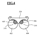
- Fig. 4 shows a section of the reflective panel 324 along the line IV - IV Fig. 3
- the illumination beam path at the reflex stop 324 has an optical axis 318 and a optical axis 319 with cross-sectional areas 403 and 404. From the illumination beam path in the areas 405 and 406 by means of the reflective aperture 324 those illumination beams are shadowed, which after deflecting by the deflecting element 113 by reflections on the microscope main objective 101 in Fig. 1 Induce scattered light, the about the magnification system 103 in the surgical microscope 100 from Fig. 1 so that the observational image visible to an observer in the binocular tube 104 is compromised.
- Fig. 5 shows a 3-dimensional view of a central unit 500 of the lighting device 110 from Fig. 1 , As far as the modules of the unit 500 in the FIGS. 1 . 2 . 3 or 4 can be seen, the same reference numerals are used to their name.
- the illumination unit unit 500 has a light guide end receptacle 501 that provides light for off-axis illumination.
- the unit 500 comprises a receptacle 502 for a light guide end, emerges from the light for near-axis illumination light.
- a rotary knob 503 is provided which can be rotated about an axis 504 corresponding to the double arrow 505.
- the rotary knob 503 is connected to a shaft 506 in which a first control cam 507, a second control cam 508 and a third control cam 509 is formed.
- the first control cam 507 is operatively connected to a first output unit 510, by means of which the diaphragm 302 is made Fig. 3 can be adjusted.
- the second control cam 508 acts on a second output unit 511, around the retinal protective shield 202 Fig. 2 to adjust.
- the third control cam 509 is in operative connection with a third output element 512 which forms the diaphragm 205 Fig. 2 controls.
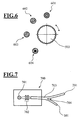
- the FIG. 6 shows various possible settings of the knob 503 Fig. 5 ,
- the setting 601 the beam path for off-axis illumination light is obstructed and only near-illumination light is guided to the object area.
- the setting 602 takes the Intensity of that illumination light, which is guided in the surgical microscope with off-axis course with respect to the optical axis of the observation beam path to the object area.
- both near-axis and off-axis illumination light is provided.
- the knob 503 can be moved to the position 603.
- the beam path for near-axis illumination light is interrupted and only off-axis illumination light is guided to the object area.
- a setting 604 is possible for the rotary knob 503.
- the beam path for near-axis illumination light is interrupted.
- illumination light is provided corresponding to the illumination beam path for off-axis illumination light, wherein the retinal protection diaphragm is switched on in the illumination beam path.
- the illumination device 110 of the surgical microscope 100 Fig. 1 is associated with a light source 700, which in Fig. 7 is shown.
- the light source 700 comprises a halogen lamp 701, whose light is fed via an optical unit 702 to a light guide 703.
- a light guide 703 has a branch 704 for providing illuminating light for off-axis illumination at a first exit end 201.
- the light guide has a second exit end 301, out of the light for near-axis illumination of the object area in the surgical microscope 100 Fig. 1 exit.
- the Fig. 8 shows the exit end 301 of the light guide 703. Exit end 301 is formed as a light exit unit having a first illumination pupil 314 and a second illumination pupil 315.
- Fig. 9 the exit end 201 of the light guide 703 is shown.
- the exit end 201 also acts as a light exit unit. Here, however, there is only one illumination pupil 901.
- the illumination device 110 of the in Fig. 1 shown operating microscope 100 allows extremely versatile illumination of the object area 105 of the Operation Microscope 100: By Adjusting the Aperture 302 Fig. 3 In the illumination beam path 111 for near-illumination light, the brightness of a red reflex caused on a patient's eye can be adjusted.
- the diaphragm 302 is placed in the illumination beam path 111 of the surgical microscope 100 so that when the diaphragm 302 is closed, the light field becomes uniformly darker without unilateral shadowing or diminishing of the illumination field diameter.
- the diaphragm 205 is in turn placed in the beam path 112 in such a way that the light field caused by the beam path 112 in the object region 105 of the surgical microscope is uniformly darker when it is dark, without unilateral shading or the light field diameter being reduced.
- the illumination of the object area exclusively with achsnahem illumination light from the illumination beam path 111 from Fig. 1 is particularly advantageous when using video documentation systems. If no off-axis illumination light reaches the subject area, a patient's eye is prevented from scattering excess light on its skelera. This results in a good image contrast and it is avoided that due to an automatic adjustment of exposure time or amplification by means of a camera captured images of a patient's eye in the area of the pupil are too dark and too low contrast.
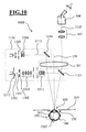
- the Fig. 10 shows another surgical microscope 1000.
- the assemblies of the surgical microscope 100 from Fig. 1 same, these are in Fig. 10 identical reference numerals as in Fig. 1 assigned.
- the surgical microscope 1000 is in turn designed as an ophthalmic surgical microscope and is particularly suitable for Examination of a patient's eye 106 arranged in an object area 105.
- the object plane 355 lies in the region of the cornea 361 of the patient's eye 106, ie the surgical microscope is focused on the cornea of the patient's eye.
- the surgical microscope 1000 includes a lighting device 1110, which provides a first illumination beam path 1111 for near-axis illumination with respect to the stereoscopic observation beam path 102 and a second illumination beam path 1112 for off-axis illumination of the object region.
- the illumination device 1110 comprises a light-transmissive mirror 1113, which acts as a first deflection element to superimpose illumination light on the stereoscopic observation beam path 102 on the side of the microscope main objective 101 assigned to the object.
- the illumination device 1110 includes a mirror 1114 as the second deflection element, which directs the illumination light remote from the axis to the object region 105 through the microscope main objective 101.
- the basic structure of the illumination device 1110 corresponds to that of the illumination device 110 Fig. 1
- illumination optics 1303, 1311 in the illumination device 1110 a light exit unit 1301 in a light exit plane 1313 in the first illumination beam path 1111 is imaged by an adjustable aperture stop 1302 into a first image plane 350.
- the second illumination beam path 1112 contains a field diaphragm 1203, which is imaged with illumination optics 1204 through the microscope main objective into a second image plane 250 different from the first image plane 350.
- the illumination optics 1302, 1303, 1311 is designed so that an illumination spot 1322 is generated on the retina 363 of the patient's eye 106, the diameter of which is in the range 0.5 mm to 1.5 mm.
- FIG. 11 Another surgical microscope is in Fig. 11 shown.
- the surgical microscope 2000 in Fig. 11 has 1000 according to the surgical microscope Fig. 10 a microscope main lens 101 with an optical axis 150, which is a stereoscopic Observation beam 102 is penetrated. It allows an observer via an enlargement system 103 and a binocular tube 104 to examine an object region 105 in an object plane 355.
- the surgical microscope 2000 is also designed as an ophthalmic surgical microscope for examining a patient's eye 106.
- the surgical microscope 2000 includes a lighting device 2110, which provides a first illumination beam path 2111 for near-axis illumination and a second illumination beam path 2112 for achs distant illumination of the object area with respect to the stereoscopic observation beam path 102.
- the illumination device 2110 comprises a light-transmissive mirror 2113, which acts as a first deflection element to superimpose illumination light on the stereoscopic observation beam path 102 on the side of the microscope main objective 101 assigned to the object.
- the illumination device 2110 includes a mirror 2114 as the second deflection element, which directs the illumination light away from the microscope main objective 101 past the object region 105.
- the operation of the illumination device 2110 corresponds to that of the illumination device 110 Fig. 1 or 1110 off Fig. 10
- a light exit unit 2301 with a light exit plane 2323 in the first illumination beam path 2111 is imaged by an adjustable aperture stop 2302 into a first image plane 350.
- the second illumination beam path 2112 contains a field diaphragm 2203, which in turn is imaged with an illumination optical unit 2204 into a second image plane 250 that is different from the first image plane 350.
- the illumination optics 2302, 2303, 2311 in the first illumination beam path is likewise designed so that an illumination spot 2322 is generated on the retina 363 of the patient's eye 106, the diameter of which is in the range 0.5 mm to 1.5 mm.
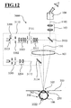
- the Fig. 12 shows a surgical microscope 3000.
- the surgical microscope 3000 has a microscope main objective 101 with an optical axis 150, which is penetrated by a stereoscopic observation beam 102. It allows one Observant on a magnification system 103 and a binocular tube 104 to examine an object area 105 in an object plane 355.
- the surgical microscope 3000 is likewise designed as an ophthalmic surgical microscope and is therefore particularly suitable for examining a patient's eye 106.
- the surgical microscope 3000 in turn contains, like the surgical microscopes described above, a lighting device 3110, which provides a first illumination beam path 3111 for near-axis illumination and a second illumination beam path 3112 for achs distant illumination of the object area with respect to the stereoscopic observation beam path 102.
- the illumination device 3110 comprises a light-permeable mirror 3113, which acts as a first deflection element to superimpose illumination light on the stereoscopic observation beam path 102 through the microscope main objective 101.
- the illumination device 3110 contains a mirror 3114 as the second deflection element, which directs the illumination light away from the microscope main objective 101 past the object region 105.
- a light exit unit 3301 with a light exit plane 3323 in the first illumination beam path 3111 is imaged into a first image plane 350.
- the second illumination beam path 3112 contains a field diaphragm 3203, which in turn is imaged by illumination optics 3204 into a second image plane 250 different from the first image plane 350.
- the illumination optics 3302, 3303, 3311 and 101 in the first illumination beam path 3111 of the illumination device 3110 is designed so that an illumination spot 3322 is generated on the retina 363 of the patient's eye 106, whose diameter is in the range 0.5 mm to 1.5 mm.
- a surgical microscope having a plurality of stereoscopic observation beam paths, such as a main observation stereoscopic observation beam path and a co-observation stereoscopic observation beam path
- a first illumination beam path providing illuminating light guided to the object section with a plurality of optical axes which correspond to the optical axes of the observation beam paths.
Description
Die Erfindung betrifft ein Operationsmikroskop mit einer Beleuchtungseinrichtung, die mit einem ersten Beleuchtungsstrahlengang und mit einem zweiten Beleuchtungsstrahlengang Beleuchtungslicht für den Objektbereich bereitstellen kann, wobei zum Bereitstellen von Licht in dem ersten Beleuchtungsstrahlengang eine erste Lichtaustrittseinheit vorgesehen ist und in dem zweiten Beleuchtungsstrahlengang eine Leuchtfeldblende angeordnet ist, und wobei der erste Beleuchtungsstrahlengang eine Beleuchtungsoptik aufweist, welche die Lichtaustritts-Ebene der ersten Lichtaustrittseinheit oder eine zu dieser Lichtaustritts-Ebene konjugierte Ebene in eine erste Bildebene abbildet.The invention relates to a surgical microscope with an illumination device which can provide illumination light for the object region with a first illumination beam path and with a second illumination beam path, a first light emission unit being provided for providing light in the first illumination beam path and a field diaphragm being arranged in the second illumination beam path. and wherein the first illumination beam path has an illumination optical system which images the light exit plane of the first light exit unit or a plane conjugate to this light exit plane into a first image plane.
Ein Operationsmikroskop der eingangs genannten Art ist aus der
Beim Einsatz von Operationsmikroskopen in der Chirurgie werden je nach medizinischer Fachrichtung verschiedene Forderungen an die Beleuchtung des Operationsfeldes gestellt: Bei Operationen in der Hals-, Nasen-, Ohren- und Neurochirurgie wird das Operationsfeld im Bezug auf die Beobachtungsstrahlengänge mit achsnaher Schrägbeleuchtung ausgeleuchtet, damit insbesondere enge, tiefe Körperhöhlen ohne Schattenbildung ausgeleuchtet werden können. Bei mikrochirurgischen Eingriffen am Auge wird diffus von der Netzhaut reflektiertes Beleuchtungslicht verwendet, das einem Operateur, der die Linse eines Patientenauges untersucht, als rötliches Durchlicht erscheint, um transparente Strukturen im vorderen Bereich eines Patientenauges sichtbar zu machen.When surgical microscopes are used in surgery, various demands are placed on the illumination of the operating field, depending on the medical discipline. Operations in the ear, nose and throat surgery and neurosurgery become the surgical field illuminated in relation to the observation beam paths with oblique illumination close to the axis, so that in particular narrow, deep body cavities can be illuminated without shadowing. In microsurgical procedures on the eye, diffuse light reflected by the retina is used, which appears as a reddish transmitted light to an operator examining the lens of a patient's eye, to visualize transparent structures in the anterior region of a patient's eye.
Bei ophthalmologischen Operationen ist es günstig, wenn ein Operateur in einem Operationsmikroskop die Möglichkeit hat, in Bezug auf die optische Achse der Beobachtungsstrahlengänge das Operationsfeld mit Beleuchtungslicht unter unterschiedlichen Winkeln auszuleuchten, um auf diese Weise den Kontrast des Beobachtungsbildes einstellen zu können.In ophthalmological operations, it is favorable if a surgeon in a surgical microscope has the possibility to illuminate the surgical field with illumination light at different angles with respect to the optical axis of the observation beam paths in order to be able to adjust the contrast of the observation image.
In der
Die
In der nicht veröffentlichten deutschen Patentanmeldung Nr.
Aus der
In der
Die
Die
Die
Aufgabe der Erfindung ist es, ein Operationsmikroskop bereitzustellen, das sich zum Einsatz in der Ophthalmologie eignet und ermöglicht, transparente Strukturen im vorderen Abschnitt eines Patientenauges mit gutem Kontrast sichtbar zu machen.The object of the invention is to provide a surgical microscope which is suitable for use in ophthalmology and makes it possible to visualize transparent structures in the anterior section of a patient's eye with good contrast.
Diese Aufgabe wird durch ein Operationsmikroskop der eingangs genannten Art gelöst, bei dem in dem zweiten Beleuchtungsstrahlengang eine Beleuchtungsoptik vorgesehen ist, welche die Leuchtfeldblende in eine, von der ersten Bildebene verschiedene zweite Bildebene abbildet.This object is achieved by a surgical microscope of the type mentioned above, in which an illumination optical unit is provided in the second illumination beam path, which images the field diaphragm into a second image plane different from the first image plane.
Der erste Beleuchtungsstrahlengang ist relativ zu wenigstens einer optischen Achse des Beobachtungsstrahlenganges des Operationsmikroskops mit einem achsnahen Verlauf zum Objektbereich gerührt. Auf diese Weise lässt sich an einem Patientenauge ein roter Reflex mit guter Homogenität erzeugen.The first illumination beam path is moved relative to at least one optical axis of the observation beam path of the surgical microscope with a course close to the axis to the object region. In this way, a red reflex with good homogeneity can be generated on a patient's eye.
Der zweite Beleuchtungsstrahlengang ist relativ zu wenigstens einer optischen Achse des Operationsmikroskops mit einem achsfernen Verlauf zum Objektbereich geführt. Auf diese Weise wird eine gute Plastizität eines Bildes des Objektbereichs im Operationsmikroskop bewirkt, da das schräg einfallende Beleuchtungslicht an Strukturen im Objektbereich Schattenbildung hervorruft.The second illumination beam path is guided relative to at least one optical axis of the surgical microscope with an off-axis course to the object area. In this way, a good plasticity of an image of the object area is effected in the surgical microscope, since the obliquely incident illumination light causes structures in the object area shadowing.
Die zweite Bildebene, in der das Bild der Leuchtfeldblende im zweiten Beleuchtungsstrahlengang liegt, fällt mit der Objektebene des Operationsmikroskops zusammen oder liegt in deren Nähe. Auf diese Weise wird eine saubere Begrenzung des Leuchtfeldes im Objektbereich bewirkt.The second image plane, in which the image of the field stop lies in the second illumination beam path, coincides with or lies in the vicinity of the object plane of the surgical microscope. In this way, a clean limitation of the light field in the object area is effected.
Insgesamt wird auf diese Weise ein Operationsmikroskop geschaffen, bei dem ein großes Leuchtfeld mit sauberer Begrenzung gewährleistet ist und bei dem gleichzeitig ein lichtstarker roter Reflex an einem untersuchten Patientenauge erzeugt werden kann.Overall, a surgical microscope is created in this way, in which a large light field is guaranteed with clean boundary and in which at the same time a bright red reflex can be generated on a patient's eye examined.
In Weiterbildung der Erfindung durchsetzt bei dem Operationsmikroskop der erste Beleuchtungsstrahlengang und/oder der zweite Beleuchtungsstrahlengang das Mikroskop-Hauptobjektiv. Auf diese Weise wird ein großer freier Arbeitsbereich zwischen Mikroskop-Hauptobjektiv und Objektbereich ermöglicht.In a development of the invention, in the surgical microscope the first illumination beam path and / or the second illumination beam path penetrate the microscope main objective. In this way, a large free working area between the microscope main objective and the object area is made possible.
In Weiterbildung der Erfindung ist in dem Operationsmikroskop ein erstes oder ein zweites Umlenkelement vorgesehen, das achsnahes bzw. achsfernes Beleuchtungslicht durch das Mikroskop-Hauptobjektiv zum Objektbereich lenkt. Auf diese Weise wird ein im Bezug auf die optische Achse des Mikroskop-Hauptobjektivs seitliches Einkoppeln von Beleuchtungslicht in das System ermöglicht.In a further development of the invention, a first or a second deflection element is provided in the surgical microscope, which directs near-axis or off-axis illumination light through the microscope main objective to the object area. In this way, a lateral coupling of illumination light into the system with respect to the optical axis of the microscope main objective is made possible.
In Weiterbildung der Erfindung ist das erste Umlenkelement als teildurchlässiger Spiegel ausgebildet, der von einem Beobachtungsstrahlengang des Operationsmikroskops durchsetzt wird. Der teildurchlässige Spiegel kann insbesondere als geometrischer oder physikalischer Strahlteiler ausgeführt sein. Auf diese Weise kann ein Strahlengang für Beleuchtungslicht ohne Vignettierung nahe bei den Beobachtungsstrahlengängen des Operationsmikroskops geführt werden.In a further development of the invention, the first deflection element is designed as a partially transmissive mirror, which is penetrated by an observation beam path of the surgical microscope. The partially transparent mirror can be designed in particular as a geometric or physical beam splitter. In this way, a beam path for illumination light without vignetting can be guided close to the observation beam paths of the surgical microscope.
In Weiterbildung der Erfindung dient das erste Umlenkelement dazu, einem stereoskopischen Beobachtungsstrahlengang, vorzugsweise einem linken und einem rechten stereoskopischen Beleuchtungsstrahlengang, achsnahes Beleuchtungslicht koaxial zu überlagern. Auf diese Weise wird Beleuchtungslicht koaxial zum Beobachtungsstrahlengang auf den Objektbereich gerührt. So kann in der Ophthalmologie an einem Patientenauge ein besonders lichtstarker und homogener, roter Reflex erzielt werden.In a further development of the invention, the first deflecting element serves to coaxially superimpose a stereoscopic observation beam path, preferably a left and a right stereoscopic illumination beam path, illumination light close to the axis. In this way, illumination light is moved coaxially to the observation beam path on the object area. Thus, in ophthalmology, a particularly bright and homogeneous, red reflex can be achieved on a patient's eye.
In Weiterbildung der Erfindung ist ein zweites Umlenkelement vorgesehen, das Beleuchtungslicht durch das Mikroskop-Hauptobjektiv zum Objektbereich lenkt. Auf diese Weise wird eine kompakte Bauform des Operationsmikroskops ermöglicht.In a further development of the invention, a second deflection element is provided which directs illumination light through the microscope main objective to the object region. In this way, a compact design of the surgical microscope is possible.
In Weiterbildung der Erfindung ist die zweite Leuchtfeldblende als Blende mit variierbarer, insbesondere einstellbarer Blendenöffnung ausgebildet. Auf diese Weise kann die Größe des Leuchtfeldes im Objektbereich eingestellt werden.In a further development of the invention, the second field diaphragm is designed as a diaphragm with a variable, in particular adjustable diaphragm opening. In this way, the size of the light field in the object area can be adjusted.
In Weiterbildung der Erfindung ist bei der Leuchtfeldblende eine weitere Blende angeordnet. Vorzugsweise ist die weitere Blende als Retinaschutzblende ausgebildet. Auf diese Weise kann die Belastung der Retina mit Beleuchtungslicht bei ophthalmologischen Operationen reduziert bzw. unterbunden werden.In a further development of the invention, a further diaphragm is arranged in the field diaphragm. Preferably, the further diaphragm is designed as Retinaschutzblende. In this way, the exposure of the retina to illumination light in ophthalmological operations can be reduced or prevented.
In Weiterbildung der Erfindung ist in dem zweiten Beleuchtungsstrahlengang eine Aperturblende angeordnet. Vorzugsweise ist diese Aperturblende einstellbar ausgeführt.In a further development of the invention, an aperture diaphragm is arranged in the second illumination beam path. Preferably, this aperture diaphragm is made adjustable.
Mit dieser Maßnahme kann die Helligkeit des Leuchtfeldes bei dem Operationsmikroskop variiert werden, ohne dass es hierfür der Steuerung einer Lichtquellenleistung bedarf.With this measure, the brightness of the light field in the surgical microscope can be varied without the need to control a light source power for this purpose.
In Weiterbildung der Erfindung ist in dem ersten Beleuchtungsstrahlengang eine Blende mit variierbarer, insbesondere einstellbarer Blendenöffnung ausgebildet, um die Lichtmenge in dem Strahlengang zu steuern. Auf diese Weise kann die Helligkeit des Rotreflexes in der Ophthalmologie ohne Steuerung einer Lichtquellenleistung verändert werden.In a further development of the invention, a diaphragm with a variable, in particular adjustable diaphragm opening is formed in the first illumination beam path in order to control the amount of light in the beam path. In this way, the brightness of the red reflex in ophthalmology can be changed without controlling a light source power.
In Weiterbildung der Erfindung ist zur Einstellung der Blende in dem zweiten Beleuchtungsstrahlengang und/oder der Aperturblende und/oder der Blende in dem ersten Beleuchtungsstrahlengang ein gemeinsames benutzerbetätigbares Bedienelement vorgesehen. Auf diese Weise wird ein ergonomisch günstig handhabbares Operationsmikroskop bereitstellt.In a development of the invention, a common user-operable control element is provided for adjusting the diaphragm in the second illumination beam path and / or the aperture diaphragm and / or the diaphragm in the first illumination beam path. In this way, an ergonomically manageable surgical microscope is provided.
In Weiterbildung der Erfindung ist das benutzerbetätigbare Bedienelement als Drehknopf ausgebildet. Auf diese Weise wird eine sichere Einstellung von Blendenkonfigurationen ermöglicht, wobei Fehlbedienungen weitestgehend ausgeschlossen werden können, die eine Schädigung eines Patientenauges mit Beleuchtungslicht zur Folge hätten.In a further development of the invention, the user-operable control element is designed as a rotary knob. In this way, a safe adjustment of aperture configurations is made possible, with incorrect operation can be largely excluded, which would result in damage to a patient's eye with illumination light.
In Weiterbildung der Erfindung ist der Drehknopf mit einer Welleneinheit gekoppelt, die über eine erste Steuerkurve sowie einer ersten Abtriebseinheit mit der Blende im ersten Beleuchtungsstrahlengang in Wirkverbindung steht, die über eine zweite Steuerkurve sowie eine zweite Abtriebseinheit mit der verstellbaren Blende im zweiten Beleuchtungsstrahlengang in Wirkverbindung steht, und die über eine dritte Steuerkurve sowie eine dritte Abtriebseinheit mit der Aperturblende in Wirkverbindung steht. Auf diese Weise wird eine besonders kleine Bauform der Beleuchtungseinrichtung ermöglicht und es wird ohne elektrische Antriebe eine zuverlässige Funktionsweise des Operationsmikroskops gewährleistet.In a further development of the invention, the rotary knob is coupled to a shaft unit which is operatively connected to the diaphragm in the first illumination beam path via a first control cam and a first output unit, which is operatively connected to the adjustable diaphragm in the second illumination beam path via a second control cam and a second output unit , and which is in operative connection with the aperture diaphragm via a third control cam and a third output unit. In this way, a particularly small design of the illumination device is made possible and it is ensured without electrical drives reliable operation of the surgical microscope.
In Weiterbildung der Erfindung ist dem ersten Beleuchtungsstrahlengang und dem zweiten Beleuchtungsstrahlengang eine gemeinsame Lichtquelle zugeordnet. Auf diese Weise wird eine kostengünstige Bauform für ein Operationsmikroskop mit Beleuchtungseinrichtung geschaffen.In a development of the invention, a common light source is assigned to the first illumination beam path and the second illumination beam path. This way will created a cost-effective design for a surgical microscope with lighting device.
In Weiterbildung der Erfindung ist bei dem Operationsmikroskop ein Lichtleiter mit Verzweigung vorgesehen, der das Licht der gemeinsamen Lichtquelle dem ersten Beleuchtungsstrahlengang und dem zweiten Beleuchtungsstrahlengang zuführt. Auf diese Weise kann bei dem Operationsmikroskop die Lichtquelle mit Abstand von der Optik des Operationsmikroskops angeordnet werden.In a further development of the invention, a light guide with branching is provided in the surgical microscope, which supplies the light of the common light source to the first illumination beam path and the second illumination beam path. In this way, in the surgical microscope, the light source can be arranged at a distance from the optics of the surgical microscope.
In Weiterbildung der Erfindung weist der Lichtleiter eine erste Lichtaustrittseinheit und eine zweite Lichtaustrittseinheit auf. Auf diese Weise ist es möglich, unter Verwendung einer einzigen Lichtquelle Beleuchtungslicht für einen achsnahen und einen achsfernen Beleuchtungsstrahlengang gleichzeitig bereitzustellen.In a development of the invention, the light guide has a first light exit unit and a second light exit unit. In this way, it is possible to simultaneously provide illumination light for a near-axis and an off-axis illumination beam path using a single light source.
In Weiterbildung der Erfindung ist an der ersten Lichtaustrittseinheit eine erste Beleuchtungspupille und eine zweite Beleuchtungspupille ausgebildet. Auf diese Weise lässt sich eine optimierte Rotreflexbeleuchtung für beide stereoskopische Beobachtungsstrahlengänge eines Operationsmikroskop erzielen.In a development of the invention, a first illumination pupil and a second illumination pupil are formed on the first light emission unit. In this way, an optimized red-reflex illumination can be achieved for both stereoscopic observation beam paths of a surgical microscope.
In Weiterbildung der Erfindung ist an der zweiten Lichtaustrittseinheit eine einzige Beleuchtungspupille ausgebildet. Auf diese Weise ist im Objektbereich des Operationsmikroskops ein homogenes Leuchtfeld darstellbar.In a development of the invention, a single illumination pupil is formed on the second light exit unit. In this way, a homogeneous illuminated field can be displayed in the object area of the surgical microscope.
In Weiterbildung der Erfindung ist in dem ersten Beleuchtungsstrahlengang des Operationsmikroskops eine Reflexblende vorgesehen, die Beleuchtungsstrahlen abschattet, welche durch Reflexionen an optischen Elementen im Operationsmikroskop, insbesondere Reflexionen am Mikroskop-Hauptobjektiv, störendes Streulicht in den Beobachtungsstrahlengängen des Operationsmikroskops hervorrufen. Auf diese Weise kann der Kontrast des Bildes, das für eine Beobachtungsperson im Binokulartubus des Operationsmikroskops sichtbar ist, maximiert werden.In a further development of the invention, a reflection diaphragm is provided in the first illumination beam path of the surgical microscope, which shadows illumination beams which cause reflections on optical elements in the surgical microscope, in particular reflections on the microscope main objective, disturbing scattered light in the observation beam paths of the surgical microscope. In this way, the contrast of the image visible to an observer in the binocular tube of the surgical microscope can be maximized.
In Weiterbildung der Erfindung ist die Reflexblende im ersten Beleuchtungsstrahlengang des Operationsmikroskops derart angeordnet, dass keine Beobachtungsstrahlen im Operationsmikroskop ausgeblendet werden und kein Beschnitt des Bildes der Leuchtfeldblende in der zweiten Bildebene durch die Reflexblende erfolgt. Auf diese Weise wird ein lichtstarkes Beobachtungsbild im Operationsmikroskop bewirkt, in dem keine störenden Reflexe auftreten, wobei das Leuchtfeld in allen Bereichen gleichmäßig ausgeleuchtet wird.In a further development of the invention, the reflected diaphragm in the first illumination beam path of the surgical microscope is arranged such that no observation beams are masked out in the surgical microscope and no trimming of the image of the field diaphragm in the second image plane by the reflective diaphragm. In this way, a bright observation image in the surgical microscope is effected, in which no disturbing reflections occur, wherein the light field is uniformly illuminated in all areas.
In Weiterbildung der Erfindung ist die Beleuchtungseinrichtung in dem Operationsmikroskop derart ausgelegt, dass auf der Retina eines idealen Patientenauges mit Beleuchtungslicht aus dem ersten Beleuchtungsstrahlengang wenigstens ein Beleuchtungsspot, vorzugsweise ein erster und ein zweiter Beleuchtungsspot mit einem Durchmesser im Bereich 0,5 mm bis 1,5 mm erzeugt werden kann. Auf diese Weise lässt sich an einem Patientenauge ein roter Reflex erzeugen, der mit exzellentem Kontrast im Operationsmikroskop sichtbar ist.In a further development of the invention, the illumination device in the surgical microscope is designed such that on the retina of an ideal patient eye with illumination light from the first illumination beam path at least one illumination spot, preferably a first and a second illumination spot with a diameter in the range 0.5 mm to 1.5 mm can be generated. In this way, a red reflex can be generated on a patient's eye, which is visible with excellent contrast in the surgical microscope.
Vorteilhafte Ausführungsformen der Erfindung sind in den Zeichnungen dargestellt und werden nachfolgend beschrieben.Advantageous embodiments of the invention are illustrated in the drawings and will be described below.
Es zeigen:
- Fig. 1
- einen schematischen Schnitt eines ersten Operationsmikroskops mit einer Beleuchtungseinrichtung, die einen ersten Beleuchtungsstrahlengang mit achsnahem Beleuchtungslicht für Rotreflexbeleuchtung und einen zweiten Beleuchtungsstrahlengang mit achsfernem Beleuchtungslicht für Umfeldbeleuchtung bereitstellt, der jeweils durch das Mikroskop-Hauptobjektiv des Operationsmikroskop geführt ist;
- Fig. 2
- einen schematischen Schnitt entlang der Linie II - II des Operationsmikroskops aus
Fig. 1 mit einem Beleuchtungsstrahlengang für Umfeldbeleuchtung; - Fig. 3
- einen schematischen Schnitt entlang der Linie III - III des Operationsmikroskops aus
Fig. 1 mit dem ersten Beleuchtungsstrahlengang für Rotreflexbeleuchtung; - Fig.4
- eine Reflexblende in dem ersten Beleuchtungsstrahlengang für Rotreflexbeleuchtung;
- Fig. 5
- eine 3-dimensionale Ansicht einer Baugruppe der Beleuchtungseinrichtung mit einem Drehknopf;
- Fig. 6
- verschiedene Einstellungen des Drehknopfs der Baugruppe;
- Fig.7
- einen Lichtleiter mit Lichtquelle, um die Beleuchtungseinrichtung des Operationsmikroskops mit Licht zu versorgen;
- Fig. 8
- ein erstes Austrittsende des Lichtleiters für Licht mit zwei Beleuchtungspupillen;
- Fig.9
- ein zweites Austrittsende des Lichtleiters für Licht mit einer einzigen Beleuchtungspupille;
- Fig. 10
- einen schematischen Schnitt eines zweiten Operationsmikroskops mit einer Beleuchtungseinrichtung, die einen ersten Beleuchtungsstrahlengang mit achsnahem Beleuchtungslicht bereitstellt, der am Mikroskop-Hauptobjektiv vorbei zum Objektbereich geführt ist, und eine zweiten Beleuchtungsstrahlengang umfasst, der das Mikroskop-Hauptobjektiv durchsetzt;
- Fig. 11
- einen schematischen Schnitt eines dritten Operationsmikroskops mit einer Beleuchtungseinrichtung, bei der ein erster Beleuchtungsstrahlengang mit achsfernen Beleuchtungslicht am Mikroskop-Hauptobjektiv vorbei zum Objektbereich geführt ist; und
- Fig. 12
- einen schematischen Schnitt eines vierten Operationsmikroskop mit einer Beleuchtungseinrichtung, bei der ein erster Beleuchtungsstrahlengang mit achsnahem Beleuchtungslicht durch das Mikroskop-Hauptobjektiv zum Objektbereich geführt ist und ein zweiter Beleuchtungsstrahlengang achsfernes Beleuchtungslicht an Mikroskop-Hauptobjektiv vorbei für den Objektbereich bereitstellt.
- Fig. 1
- a schematic section of a first surgical microscope with a lighting device, which provides a first illumination beam path with near-axis illumination light for red-backlighting and a second illumination beam path with off-axis illumination light for ambient lighting, which is guided by the microscope main objective of the surgical microscope;
- Fig. 2
- a schematic section along the line II - II of the surgical microscope
Fig. 1 with a lighting beam path for ambient lighting; - Fig. 3
- a schematic section along the line III - III of the surgical microscope
Fig. 1 with the first illumination beam path for red-reflex illumination; - Figure 4
- a reflection stop in the first illumination beam path for red-reflected illumination;
- Fig. 5
- a 3-dimensional view of an assembly of the lighting device with a knob;
- Fig. 6
- various settings of the rotary knob of the module;
- Figure 7
- a light guide having a light source to provide light to the illumination device of the surgical microscope;
- Fig. 8
- a first exit end of the light guide for light having two illumination pupils;
- Figure 9
- a second exit end of the light guide for light having a single illumination pupil;
- Fig. 10
- a schematic section of a second surgical microscope with a lighting device, which provides a first illumination beam path with near-axis illumination light, which is guided past the microscope main objective to the object area, and a second illumination beam path, which passes through the microscope main objective;
- Fig. 11
- a schematic section of a third surgical microscope with a lighting device in which a first illumination beam path with off-axis illumination light on the microscope main objective is passed over to the object area; and
- Fig. 12
- a schematic section of a fourth surgical microscope with a lighting device in which a first illumination beam path with near-axis illumination light is guided through the microscope main objective to the object area and a second illumination beam path provides off-axis illumination light past the microscope main objective for the object area.
Das Operationsmikroskop 100 in
Das Operationsmikroskop 100 enthält eine Beleuchtungseinrichtung 110, die in Bezug auf den stereoskopischen Beobachtungsstrahlengang 102 einen Beleuchtungsstrahlengang 111 für achsnahe Beleuchtung und einen Beleuchtungsstrahlengang 112 für achsferne Beleuchtung des Objektbereichs bereitstellt.The
Die Beleuchtungseinrichtung 110 umfasst einen für Licht teildurchlässigen Spiegel 113, der als erstes Umlenkelement wirkt, um dem stereoskopischen Beobachtungsstrahlengang zu dessen optischen Achsen 102 Beleuchtungslicht achsnah und koaxial zu überlagern. Die Beleuchtungseinrichtung 110 enthält einen Spiegel 114 als zweites Umlenkelement, der Beleuchtungslicht durch das Mikroskop-Hauptobjektiv 101 mit achsfernem Verlauf, d.h. unter einem Winkel zur optischen Achse der Beobachtungsstrahlengänge, zum Objektbereich 105 lenkt.The
Die
Der stereoskopische Beobachtungsstrahlengang 102 durchsetzt das Mikroskop-Hauptobjektiv 101 mit einem linken und einem rechten Teilstrahlengang mit optischen Achsen 161 und 162. Das Mikroskop-Hauptobjektiv 101 hat eine Brennweite von f=200 mm. Eine günstige Brennweite für das Mikroskop-Hauptobjektiv ist aber auch die Brennweite f=175 mm oder f=225 mm.The
Um achsfernes Beleuchtungslicht zum Objektbereich zu führen, wird das Licht aus einer Lichtaustrittseinheit in Form eines Lichtleiter-Austrittsendes 201 über eine einstellbare Blende 202 und eine Leuchtfeldblende 203 durch eine Beleuchtungsoptik 204 dem Spiegel 114 zugeführt, der es durch das Mikroskop-Hauptobjektiv 101 zum Objektbereich 105 lenkt.In order to guide off-axis illumination light to the object area, the light from a light exit unit in the form of a light
Die Blende 202 kann für eine Wirkung als Retinaschutzblende eingestellt werden. In dieser Einstellung befindet sich eine Ringblende in dem Beleuchtungsstrahlengang 112, die wie in der Patentschrift
Die Leuchtfeldblende 203 wird in eine Bildebene 250 abgebildet. Diese Bildebene 250 liegt nahe bei, jedoch nicht genau, in der Objektebene 355 des Operationsmikroskops 100 aus
Ist die Blende 202 für die Wirkung als Retinaschutzblende eingestellt, wird vermieden, dass Beleuchtungslicht in das Innere des Patientenauges 106 zum Augenhintergrund gelangt, wo es unter Umständen schädigende Wirkung entfalten könnte. Dabei wird die Blende 202 in den Objektbereich 105 abgebildet, d.h. bei der in
Die
Um achsnahes Beleuchtungslicht zum Objektbereich 105 zu führen, wird mit dem Licht aus einer Lichtaustrittseinheit in Form eines Lichtleiter-Austrittsendes 301 über eine einstellbare bzw. schließbare Aperturblende 302 und eine erste Beleuchtungsoptik 303 eine Leuchtfeldblende 304 ausgeleuchtet. Diese Leuchtfeldblende 304 ist in einer Ebene 305 angeordnet. Von der Leuchtfeldblende 304 wird das Beleuchtungslicht mit einem gefalteten Beleuchtungsstrahlengang über ein Spiegelelement 306, eine Doppelblende 307 mit zwei Blendenöffnungen 308 und 309 zu einem Spiegelelement 310 gelenkt. Dieses Spiegelelement 310 lenkt das Beleuchtungslicht über eine zweite Beleuchtungsoptik 311 senkrecht zur optischen Achse 150 des Mikroskop-Hauptobjektivs 101 durch eine als Streulichtblende wirkende Reflexblende 324 zu dem Umlenkelement 113, das als Strahlteiler ausgebildet ist und vom dem linken und dem rechten stereoskopischen Beobachtungsstrahlengang 102 des Operationsmikroskops durchsetzt wird. Das Umlenkelement 113 lenkt das Beleuchtungslicht parallel zur optischen Achse 150 des Mikroskop-Hauptobjektivs 101 durch das Mikroskop-Hauptobjektiv 101 koaxial mit dem stereoskopischen Beobachtungsstrahlengang 102 zum Objektbereich 105.In order to guide near-illumination light to the
Die Doppelblende 307 wirkt als Aperturblende. Sie ist in einer Ebene 312 angeordnet, welche zur Lichtaustrittsebene 313 des Lichtleiter-Austrittsendes 301 konjugiert ist. An dem Lichtleiter-Austrittsende 301 sind eine erste Lichtaustrittseinheit 314 mit einer ersten Beleuchtungspupille und eine zweite Lichtaustrittseinheit 315 mit einer zweiten Beleuchtungspupille ausgebildet. Diese erste und zweite Lichtaustrittseinheit 314, 315 wird mit der ersten Beleuchtungsoptik 303 vergrößert in die Ebene 312 der Doppelblende 307 mit den Blendenöffnungen 308 und 309 abgebildet.The
Die Leuchtfeldblende 304 wird über die Spiegelelemente 306, 310 mit der zweiten Beleuchtungsoptik 311 durch das Mikroskop-Hauptobjektiv 101 in die Bildebene 250 im Objektbereich 105 abgebildet. D.h., die Ebene 305 der Leuchtfeldblende 304 ist zu dieser Bildebene 250 konjugiert. Damit ergibt sich wiederum eine saubere Begrenzung des mit diesem Beleuchtungsstrahlengang hervorgerufenen Leuchtfeldes im Objektbereich.The
Die Blendenöffnungen 308, 309 der Doppelblende 307 werden über das Spiegelelement 310, die zweite Beleuchtungsoptik 311 durch das Mikroskops-Hauptobjektiv 101 und das Patientenauge 106 in eine von der Bildebene 250 der Leuchtfeldblende 304 verschiedene Bildebene 350 abgebildet. Die Bildebene 350 ist damit zu der Ebene 312 der Doppelblende 307 und zu der Lichtaustrittsebene 313 des Lichtleiter-Austrittsendes konjugiert. Die optische Achse 318, 319 des Abbildungsstrahlenganges für die Blendenöffnungen 308, 309 der Doppelblende 307 wird mit dem Umlenkelement 113 in die optischen Achsen 161, 162 des linken und rechten stereoskopischen Beobachtungsstrahlenganges 102 überführt.The
Zwischen Mikroskop-Hauptobjektiv 101 und dem Patientenauge 106 ist dieser Abbildungsstrahlengang parallel oder in etwa parallel. D.h., ohne die brechende Wirkung von Cornea 361 und Linse 362 des Patientenauges 106 liegt die Bildebene 350 für die Doppelblende 307 im unendlichen, bzw. sie ist von der Brennebene, d.h. der Objektebene 355 des Mikroskop-Hauptobjektivs 101 weit beabstandet. Es ist möglich, dass der entsprechende Abbildungsstrahlengang für die Doppelblende 307 austrittsseitig des Mikroskop-Hauptobjektivs 101 leicht aufgeweitet verläuft. Dann ist die Bildebene 350 ohne die brechende Wirkung von Cornea 361 und Linse 362 des Patientenauges 106 auf der dem Objekt abgewandten Seite des Mikroskop-Hauptobjektives 101 angeordnet und ist virtueller Natur. Verläuft der Abbildungsstrahlengang austrittsseitig des Mikroskop-Hauptobjektivs 101 leicht konvergent, ist die Bildebene 350 reell und befindet sich auf der dem Objekt zugewandten Seite des Mikroskop-Hauptobjektivs 101.Between the microscope
Wird mit dem Operationsmikroskop ein Patientenauge 106 untersucht, so bewirken Cornea 361 und natürliche Linse 362 im Auge, dass der parallele oder in etwa parallele Beleuchtungsstrahlengang, der entlang der optische Achsen 161, 162 verläuft, gebündelt wird. Bei einem auf unendlich adaptierten, rechtsichtigen Patientenauge 106 haben die Brechkraft von Cornea 361 und natürlichen Linse 362 zur Folge, dass der Fokus des Beleuchtungsstrahlengagens auf der Retina 363 des Patientenauges 106 liegt, also die Bildebene 350 bei der Retina 363 des Patientenauges 106 angeordnet ist. Dann befindet sich auf der Retina 363 des Patientenauges 106 ein Bild der Doppelblende 307. Auf der Retina 363 des Patientenauges 106 entsteht so ein erster Beleuchtungsspot 322 und ein zweiter Beleuchtungsspot 323.When a patient's
Die Bemaßung der Größe der Lichtaustrittseineiten 314, 315 und deren gegenseitiger Abstand, die Bemaßung der Blendenöffnungen 308, 309 und deren gegenseitiger Abstand in der Doppelblende 307 sowie die Dimensionierung der Abbildungsoptik 311 im Beleuchtungsstrahlengang und die Brennweite des Mikroskop-Hauptobjektivs 101 ist bei dem Operationsmikroskop so gewählt, dass bei Untersuchen eines idealen Patientenauges, das in seinen optischen Eigenschaften demjenigen des schematischen
- Mit zunehmender Größe des Beleuchtungsspots auf dem Augenhintergrund nimmt der Kontrast des Rotreflexbildes vom Vordergrund des Patientenauges im Operationsmikroskop ab.
- With increasing size of the illumination spot on the fundus, the contrast of the red reflex image decreases from the foreground of the patient's eye in the surgical microscope.
Besonders kleine Beleuchtungsspots werden erzielt, indem die Doppelblende 307 bzw. die Lichtaustrittsebene 313 des Lichtleiter-Austrittsendes 301 auf die Retina 363 des Patientenauges 106 abgebildet wird, d.h., wenn die Bildebene 350 auf der Retina 363, also dem Hintergrund des Patientenauges 106 liegt, das sich für eine Beobachtungsperson im Okulareinblick des Operationsmikroskops bietet.Particularly small illumination spots are achieved by imaging the
Eine zu kleine Spotgröße ist allerdings nachteilhaft: Ist die Spotgröße zu klein, so verschlechtert sich die Homogenität des roten Reflexes d.h. der rote Reflex wird in seinem peripheren Bereich nach außen dunkler. Außerdem birgt ein zu kleiner Beleuchtungsspot auf der Retina wegen der dort herrschenden hohen Bestrahlungsstärke des Beleuchtungslichts die Gefahr, dass die Netzhaut des Patientenauges geschädigt wird.However, a too small spot size is disadvantageous: if the spot size is too small, the homogeneity of the red reflex, that is, it will deteriorate. the red reflex darkens outward in its peripheral area. In addition, a too small illumination spot on the retina poses the risk that the retina of the patient's eye is damaged because of the high irradiance of the illumination light prevailing there.
Es versteht sich, dass der Beleuchtungsstrahlengang für achsnahes Beleuchtungslicht nicht unbedingt gefaltet ausgeführt sein muss, wenn ein entsprechend größeres Bauvolumen in Kauf genommen wird. Weiter ist zu bemerken, dass die Spiegelelemente 306 und 310 bzw. die Beleuchtungsoptik 303, 311 auch mehrteilig ausgeführt werden können, so dass das in den linken und rechten stereoskopischen Beobachtungsstrahlengang eingekoppelte Beleuchtungslicht über unterschiedliche Spiegel bzw. Objektive geführt wird.It is understood that the illumination beam path for near-axis illumination light does not necessarily have to be designed folded, if a correspondingly larger volume of construction is accepted. It should also be noted that the
Darüber hinaus sei bemerkt, dass der Lichtleiter-Austrittsende 301 in Ebene 312 der Doppelblende 307 angeordnet werden könnte. Mit dieser Maßnahme wird in Kauf genommen, dass der aus dem Lichtleiter-Austrittsende auftretende Beleuchtungsstrahlengang im Objektbereich kein scharf begrenztes Leuchtfeld bewirkt. Das Beleuchtungssystem kann jedoch auf diese Weise besonders platzsparend gebaut werden.In addition, it should be appreciated that the fiber
Für das Verstellen der bei Bezugszeichen 520 angeordneten Retinaschutzblende 202 aus
Die
Der Beleuchtungseinrichtung 110 des Operationsmikroskops 100 aus
Die
In
Die Beleuchtungseinrichtung 110 des in
Mittels der Blende 205 aus
Die Blende 205 ist dabei wiederum so im Strahlengang 112 platziert, dass bei Schließen das mit dem Strahlengang 112 im Objektbereich 105 des Operationsmikroskops hervorgerufene Leuchtfeld gleichmäßig dunkler wird, ohne dass es zu einseitigen Abschattungen kommt oder der Leuchtfelddurchmesser dabei verringert wird.By means of the
In this case, the
Die Beleuchtung des Objektbereichs ausschließlich mit achsnahem Beleuchtungslicht aus dem Beleuchtungsstrahlengang 111 aus
Es versteht sich, dass für das Bewegen der verstellbaren Blenden im Operationsmikroskop auch elektrische Antriebe vorgesehen werden könnten. Auch ist es möglich, die Blenden für das Steuern mit getrennten Bedienelementen auszulegen.It is understood that electrical drives could also be provided for moving the adjustable diaphragms in the surgical microscope. It is also possible to design the panels for controlling with separate controls.
Die
Das Operationsmikroskop 1000 enthält eine Beleuchtungseinrichtung 1110, die in Bezug auf den stereoskopischen Beobachtungsstrahlengang 102 einen ersten Beleuchtungsstrahlengang 1111 für achsnahe Beleuchtung und einen zweiten Beleuchtungsstrahlengang 1112 für achsferne Beleuchtung des Objektbereichs bereitstellt.The
Die Beleuchtungseinrichtung 1110 umfasst einen für Licht teildurchlässigen Spiegel 1113, der als erstes Umlenkelement wirkt, um dem stereoskopischen Beobachtungsstrahlengang 102 auf der Objekt zugeordneten Seite des Mikroskop-Hauptobjektivs 101 Beleuchtungslicht zu überlagern. Die Beleuchtungseinrichtung 1110 enthält einen Spiegel 1114 als zweites Umlenkelement, der achsfernes Beleuchtungslicht durch das Mikroskop-Hauptobjektiv 101 zum Objektbereich 105 lenkt.The
Im Übrigen entspricht der prinzipielle Aufbau der Beleuchtungseinrichtung 1110 demjenigen der Beleuchtungseinrichtung 110 aus
Ein weiteres Operationsmikroskop ist in
Das Operationsmikroskop 2000 enthält eine Beleuchtungseinrichtung 2110, die in Bezug auf den stereoskopischen Beobachtungsstrahlengang 102 einen ersten Beleuchtungsstrahlengang 2111 für achsnahe Beleuchtung und einen zweiten Beleuchtungsstrahlengang 2112 für achs ferne Beleuchtung des Objektbereichs bereitstellt.The
Die Beleuchtungseinrichtung 2110 umfasst einen für Licht teildurchlässigen Spiegel 2113, der als erstes Umlenkelement wirkt, um dem stereoskopischen Beobachtungsstrahlengang 102 auf der Objekt zugeordneten Seite des Mikroskop-Hauptobjektivs 101 Beleuchtungslicht zu überlagern. Die Beleuchtungseinrichtung 2110 enthält einen Spiegel 2114 als zweites Umlenkelement, der achsfernes Beleuchtungslicht am Mikroskop-Hauptobjektiv 101 vorbei zum Objektbereich 105 lenkt. Im Übrigen entspricht die Wirkungsweise der Beleuchtungseinrichtung 2110 derjenigen der Beleuchtungseinrichtung 110 aus
Die
Das Operationsmikroskop 3000 enthält wiederum wie die zuvor beschriebenen Operationsmikroskope eine Beleuchtungseinrichtung 3110, die in Bezug auf den stereoskopischen Beobachtungsstrahlengang 102 einen ersten Beleuchtungsstrahlengang 3111 für achsnahe Beleuchtung und einen zweiten Beleuchtungsstrahlengang 3112 für achs ferne Beleuchtung des Objektbereichs bereitstellt.The
Die Beleuchtungseinrichtung 3110 umfasst einen für Licht teildurchlässigen Spiegel 3113, der als erstes Umlenkelement wirkt, um dem stereoskopischen Beobachtungsstrahlengang 102 durch das Mikroskop-Hauptobjektiv 101 hindurch, Beleuchtungslicht zu überlagern. Die Beleuchtungseinrichtung 3110 enthält einen Spiegel 3114 als zweites Umlenkelement, der achsfernes Beleuchtungslicht am das Mikroskop-Hauptobjektiv 101 vorbei zum Objektbereich 105 lenkt.The
Wie bei dem Operationsmikroskop 100 aus
Bei den erläuterten Operationsmikroskopen wird ein guter homogener und kontrastreicher Rotreflex an einem Patientenauge erzielt, indem die optische Achsen der Beobachtungsstrahlengänge des Operationsmikroskops am Hintergrund des Patientenauges nahe bei oder in einer optischen Achse des ersten Beleuchtungsstrahlengangs liegen.In the described surgical microscopes, a good homogeneous and high-contrast red reflex is achieved on a patient's eye by the optical axes of the Observation beam paths of the surgical microscope at the background of the patient's eye are close to or in an optical axis of the first illumination beam path.
Indem ein erster Beleuchtungsstrahlengang bereitgestellt wird, der optische Achsen hat, die am Augenhintergrund nahe der optischen Achse der Beobachtungsstrahlengänge oder in der optischen Achse der Beobachtungsstrahlengänge verlaufen, wird gewährleistet, dass im linken und rechten Beobachtungsstrahlengang des Operationsmikroskops ein gleichwertiger Rotreflex sichtbar ist.By providing a first illumination beam path that has optical axes that run at the fundus near the optical axis of the observation beam paths or in the optical axis of the observation beam paths, it is ensured that an equivalent red reflex is visible in the left and right observation beam path of the surgical microscope.
Es sei bemerkt, dass es bei einem Operationsmikroskop mit mehreren stereoskopischen Beobachtungsstrahlengängen, etwa mit einem stereoskopischen Beobachtungsstrahlengang für Hauptbeobachtung und mit einem stereoskopischen Beobachtungsstrahlengang für Mitbeobachtung, günstig ist, einen ersten Beleuchtungsstrahlenganges vorzusehen, der Beleuchtungslicht bereitstellt, das mit mehreren optischen Achsen zum Objektbereich geführt wird, die den optischen Achsen der Beobachtungsstrahlengänge entsprechen. Auf diese Weise kann in sämtlichen Beobachtungsstrahlengängen eines Operationsmikroskops ein gutes, homogenes, kontrastreiches Bild des Vordergrunds eines Patientenauges unter Rotreflex sichtbar gemacht werden.It should be noted that in a surgical microscope having a plurality of stereoscopic observation beam paths, such as a main observation stereoscopic observation beam path and a co-observation stereoscopic observation beam path, it is preferable to provide a first illumination beam path providing illuminating light guided to the object section with a plurality of optical axes which correspond to the optical axes of the observation beam paths. In this way, a good, homogeneous, high-contrast image of the foreground of a patient's eye under red reflex can be made visible in all observation beam paths of a surgical microscope.
Claims (26)
- Surgical microscope (100, 1000, 2000, 3000) with an illumination device (110, 1110, 2110, 3110)- in which the illumination device (110, 1110, 2110, 3110) can provide illumination light for the object region (105) with a first illumination beam path (111, 1111, 2111, 3111) and can provide illumination light for the object region (105) with a second illumination beam path (112, 1112, 2112, 3112),- wherein provision is made for a first light-outlet unit (301, 1301, 2301, 3301) for providing light in the first illumination beam path (111, 1111, 2111, 3111); and- a field stop (203, 1203, 2203, 3203) is arranged in the second illumination beam path (112, 1112, 2112, 3112),- wherein the first illumination beam path (111, 1111, 2111, 3111) has an illumination optical system (302, 303, 306, 310, 311, 101, 1302, 1303, 1311, 2302, 2303, 2311, 3302, 3303, 3311, 101), which images the light-outlet plane (313, 1313, 2323, 3323) of the first light-outlet unit (301, 1301, 2301, 3301), or a conjugate plane to the light-outlet plane (313, 1313, 2323, 3323), at infinity in a first image plane (350),- wherein an illumination optical system (204, 101, 1204, 101, 2204, 3204) is provided in the second illumination beam path (112, 1112, 2112, 3112), which illumination optical system images the field stop (203, 1203, 2203, 3203) in a second image plane (250), which differs from the first image plane (350),- wherein, relative to at least one optical axis (161) of the observation beam path (102) of the surgical microscope, the first illumination beam path (111, 1111, 2111, 3111) is guided to the object region (105) such that it runs close to said axis,- wherein the second illumination beam path (112, 1112, 2112, 3112) is guided to the object region (105) such that it runs away from the axis with respect to at least one optical axis (161) of the observation beam path (102) of the surgical microscope, and- wherein the second image plane (250), in which the image of the field stop (203) lies in the second illumination beam path (112), lies in the vicinity of the object plane (355) or coincides with the object plane (355) of the surgical microscope (100).
- Surgical microscope according to Claim 1, characterized in that the first illumination beam path (111, 3111) passes through the main microscope objective (101).
- Surgical microscope according to Claim 2, characterized in that provision is made for a first deflection element (113, 3113), which guides illumination light to the object region (105) through the main microscope objective (101).
- Surgical microscope according to Claim 3, characterized in that the first deflection element is designed as a partly transmitting mirror (113, 3113), through which an observation beam path (102) of the surgical microscope (100) passes.
- Surgical microscope according to Claim 4, characterized in that the partly transmitting mirror (113, 3113) is designed as a physical beamsplitter or as a geometric beamsplitter.
- Surgical microscope according to Claim 3, 4, or 5, characterized in that the first deflection element (113, 3113) is used to superpose illumination light in a coaxial fashion onto a stereoscopic observation beam path (102).
- Surgical microscope according to Claim 6, characterized in that the first deflection element (113, 3113) coaxially superposes illumination light onto a left and a right illumination beam path (102).
- Surgical microscope according to one of Claims 2 to 7, characterized in that provision is made for a second deflection element (114, 1114), which guides illumination light to the object region (105) through the main microscope objective (101).
- Surgical microscope according to one of Claims 1 to 8, characterized in that an additional stop (202) is arranged at the field stop (203).
- Surgical microscope according to Claim 9, characterized in that the opening of the additional stop (202) can be varied.
- Surgical microscope according to Claim 9 or 10, characterized in that the additional stop (202) is designed as a retina protection stop.
- Surgical microscope according to one of Claims 1 to 11, characterized in that an aperture stop (205) is arranged in the second illumination beam path (112).
- Surgical microscope according to Claim 12, characterized in that the aperture stop (205) has an adjustable aperture.
- Surgical microscope according to one of Claims 1 to 13, characterized in that a stop (302) with a fixed variable aperture for changing the amount of light in the first illumination beam path (111) is formed in the first illumination beam path (111).
- Surgical microscope according to Claim 14, provided Claim 14 refers back to Claim 13 and Claim 13 refers back to Claim 12, characterized in that provision is made for a common operating element (503) that can be actuated by the user for adjusting the stop (202) in the second illumination beam path (112) and/or the aperture stop (205) in the second illumination beam path (112) and/or the stop (302) in the first illumination beam path (111).
- Surgical microscope according to Claim 15, characterized in that the operating element that can be actuated by the user is designed as a knob (503).
- Surgical microscope according to Claim 16, characterized in that the knob (503) is coupled to a shaft unit (506), which is operatively connected to the stop (302) in the first illumination beam path (111) via a first radial cam (507) and a first driven unit (510), which shaft unit is operatively connected to the stop (202) in the second illumination beam path (112) via a second radial cam (508) and a second driven unit (511), and which shaft unit is operatively connected to the aperture stop (205) via a third radial cam (509) and a third driven unit (512).
- Surgical microscope according to one of Claims 1 to 17, characterized in that a common light source (700) is assigned to the first illumination beam path (111) and the second illumination beam path (112).
- Surgical microscope according to Claim 18, characterized in that provision is made for an optical waveguide (703) with a branching (704), which optical waveguide feeds the light from the common light source (700) to the first illumination beam path (111) and the second illumination beam path (112).
- Surgical microscope according to Claim 19, characterized in that the optical waveguide (703) has the first light-outlet unit (301) and a second light-outlet unit (201).
- Surgical microscope according to one of Claims 1 to 20, characterized in that a first illumination pupil (314) and a second illumination pupil (315) are formed on the first light-outlet unit (301).
- Surgical microscope according to Claim 20 or Claim 21, characterized in that a single illumination pupil (901) is formed on the second light-outlet unit (201).
- Surgical microscope according to one of Claims 1 to 22, characterized in that provision is made for a reflection stop (324) in the first illumination beam path (111), the former shadowing illumination beams that cause distracting stray light in the observation beam paths of the surgical microscope (100), which stray light is the result of reflections on optical elements in the surgical microscope.
- Surgical microscope according to Claim 23, characterized in that the reflection stop (324) is arranged such that no observation beams are masked in the surgical microscope and no image of the field stop (203) is trimmed in the second image plane (250) by the reflection stop (324).
- Surgical microscope according to one of Claims 1 to 24, characterized in that the illumination device (110, 1110, 2110, 3110) is designed such that an illumination spot (322, 323) with a diameter in the region of 0.5 mm to 1.5 mm can be generated on the retina (363) of an ideal patient eye (106) by illumination light from the first illumination beam path (111, 1111, 2111, 3111).
- Surgical microscope according to Claim 25, characterized in that the illumination device (110, 1110, 2110, 3110) is designed such that two illumination spots, each with a diameter in the region of 0.5 mm to 1.5 mm, can be generated on the retina (363) of an ideal patient eye (106) by illumination light from the first illumination beam path (111, 1111, 2111, 3111).
Applications Claiming Priority (2)
| Application Number | Priority Date | Filing Date | Title |
|---|---|---|---|
| DE102007025606 | 2007-05-31 | ||
| DE102007041003A DE102007041003A1 (en) | 2007-05-31 | 2007-08-29 | Surgical microscope with illumination device |
Publications (2)
| Publication Number | Publication Date |
|---|---|
| EP1997423A1 EP1997423A1 (en) | 2008-12-03 |
| EP1997423B1 true EP1997423B1 (en) | 2011-07-06 |
Family
ID=39643166
Family Applications (1)
| Application Number | Title | Priority Date | Filing Date |
|---|---|---|---|
| EP08156255A Active EP1997423B1 (en) | 2007-05-31 | 2008-05-15 | Operation microscope with illumination device |
Country Status (1)
| Country | Link |
|---|---|
| EP (1) | EP1997423B1 (en) |
Cited By (1)
| Publication number | Priority date | Publication date | Assignee | Title |
|---|---|---|---|---|
| EP2960704A1 (en) | 2014-06-26 | 2015-12-30 | Carl Zeiss Meditec AG | Lighting device of an operation microscope |
Families Citing this family (5)
| Publication number | Priority date | Publication date | Assignee | Title |
|---|---|---|---|---|
| DE102012203266A1 (en) | 2012-03-01 | 2013-09-05 | Leica Microsystems (Schweiz) Ag | Microscope with switchable documentation beam path |
| DE102013226288A1 (en) | 2013-12-17 | 2015-06-18 | Carl Zeiss Meditec Ag | surgical microscope |
| DE102013226784A1 (en) * | 2013-12-19 | 2015-06-25 | Leica Microsysteme (Schweiz) AG | surgical microscope |
| CN107911909A (en) * | 2017-12-14 | 2018-04-13 | 苏州西默医疗科技有限公司 | A kind of surgical operation microscope and its continuously adjustable method of illumination colour temperature |
| CN111474699B (en) * | 2020-04-09 | 2022-08-30 | 浙江未来技术研究院(嘉兴) | Operation microscope with programmable aperture |
Family Cites Families (8)
| Publication number | Priority date | Publication date | Assignee | Title |
|---|---|---|---|---|
| DE3339172A1 (en) | 1983-10-28 | 1985-05-15 | Fa. Carl Zeiss, 7920 Heidenheim | LIGHT TRAP FOR EYE EXAMINATION DEVICES |
| DE4344770A1 (en) | 1993-12-28 | 1995-06-29 | Leica Ag | Switchable lighting device for a surgical microscope |
| JPH08257037A (en) | 1995-03-20 | 1996-10-08 | Nikon Corp | Microscope for operation |
| JP3062542U (en) * | 1999-07-01 | 1999-10-08 | 株式会社オービック・ビジネス・コンサルタント | Electronic banking device for multiple communication programs |
| EP1109046B1 (en) | 1999-12-15 | 2002-09-25 | Möller-Wedel GmbH | Illumination system for an operation microscope |
| EP1410754B1 (en) * | 2002-10-16 | 2006-05-24 | Möller-Wedel GmbH | Surgical microscope with illumination means |
| DE10304267B9 (en) * | 2003-02-03 | 2006-06-29 | Carl Zeiss | Eye surgery microscopy system |
| DE202004019849U1 (en) | 2004-12-23 | 2005-02-24 | Leica Microsystems (Schweiz) Ag | Eye surgery operating microscope has a light source with a diffuser between it and the objective plane to produce more homogenous illumination |
-
2008
- 2008-05-15 EP EP08156255A patent/EP1997423B1/en active Active
Cited By (2)
| Publication number | Priority date | Publication date | Assignee | Title |
|---|---|---|---|---|
| EP2960704A1 (en) | 2014-06-26 | 2015-12-30 | Carl Zeiss Meditec AG | Lighting device of an operation microscope |
| DE102014212372A1 (en) | 2014-06-26 | 2015-12-31 | Carl Zeiss Meditec Ag | Illumination device of a surgical microscope |
Also Published As
| Publication number | Publication date |
|---|---|
| EP1997423A1 (en) | 2008-12-03 |
Similar Documents
| Publication | Publication Date | Title |
|---|---|---|
| DE102007041003A1 (en) | Surgical microscope with illumination device | |
| DE102009036913B4 (en) | Surgical microscope with illumination device | |
| EP2452616B1 (en) | Observation device | |
| DE102016001659B4 (en) | Eye surgery microscope and eye surgery accessory | |
| DE102016203473B4 (en) | eye microscope | |
| EP1955103B1 (en) | Microscope for ophthalmologic surgery | |
| DE102016203487B4 (en) | ophthalmic microscope system | |
| DE102005032501A1 (en) | Instrument for the examination of a patient's eye combines the functions of a slit lamp and an ophthalmoscope, to examine the eye structure from the front to the back | |
| EP1997423B1 (en) | Operation microscope with illumination device | |
| DE102011088038B4 (en) | Surgical microscope system for ophthalmology and associated detection unit | |
| DE102009017710B4 (en) | An optical observation device and method for ensuring a constant illumination intensity when the color temperature of the illumination changes | |
| EP1455215B2 (en) | Microscope illuminating apparatus | |
| DE102012221955A1 (en) | Illumination device for a surgical microscope | |
| DE102006038911A1 (en) | Ophthalmoscopy attachment module and surgical microscope with ophthalmoscopy attachment module | |
| DE2914675A1 (en) | LIGHT COAGULATOR | |
| DE102011114523A1 (en) | Module for transmitting a light beam | |
| DE10144067A1 (en) | Prism construction for simultaneous 0 DEG - and oblique illumination of a stereo surgical microscope | |
| EP1891890A1 (en) | Optical device, use of a an optical device according to the present invention and method for blocking light reflexes in the observation optical path of an optical device | |
| WO2005039404A1 (en) | Illumination unit for fundus cameras and/or ophthalmoscopes | |
| DE2202120A1 (en) | OPTICAL DEVICE FOR GENERATING COAGULATIONS, PREFERABLY ON THE RETINES OF ONE EYE | |
| DE202007012431U1 (en) | Surgical microscope with a lighting device | |
| DE102012203266A1 (en) | Microscope with switchable documentation beam path | |
| DE102011085527A1 (en) | Illumination device for a stereomicroscope, in particular a surgical microscope | |
| DE19932643A1 (en) | Surgical microscope | |
| DE102013206839A1 (en) | Surgical microscope with red reflex illumination |
Legal Events
| Date | Code | Title | Description |
|---|---|---|---|
| PUAI | Public reference made under article 153(3) epc to a published international application that has entered the european phase |
Free format text: ORIGINAL CODE: 0009012 |
|
| AK | Designated contracting states |
Kind code of ref document: A1 Designated state(s): AT BE BG CH CY CZ DE DK EE ES FI FR GB GR HR HU IE IS IT LI LT LU LV MC MT NL NO PL PT RO SE SI SK TR |
|
| AX | Request for extension of the european patent |
Extension state: AL BA MK RS |
|
| 17P | Request for examination filed |
Effective date: 20090116 |
|
| 17Q | First examination report despatched |
Effective date: 20090220 |
|
| AKX | Designation fees paid |
Designated state(s): DE ES FR GB IT |
|
| GRAP | Despatch of communication of intention to grant a patent |
Free format text: ORIGINAL CODE: EPIDOSNIGR1 |
|
| GRAS | Grant fee paid |
Free format text: ORIGINAL CODE: EPIDOSNIGR3 |
|
| GRAA | (expected) grant |
Free format text: ORIGINAL CODE: 0009210 |
|
| AK | Designated contracting states |
Kind code of ref document: B1 Designated state(s): DE ES FR GB IT |
|
| REG | Reference to a national code |
Ref country code: GB Ref legal event code: FG4D Free format text: NOT ENGLISH |
|
| REG | Reference to a national code |
Ref country code: DE Ref legal event code: R096 Ref document number: 502008004104 Country of ref document: DE Effective date: 20110825 |
|
| REG | Reference to a national code |
Ref country code: ES Ref legal event code: FG2A Ref document number: 2366760 Country of ref document: ES Kind code of ref document: T3 Effective date: 20111025 |
|
| PLBE | No opposition filed within time limit |
Free format text: ORIGINAL CODE: 0009261 |
|
| STAA | Information on the status of an ep patent application or granted ep patent |
Free format text: STATUS: NO OPPOSITION FILED WITHIN TIME LIMIT |
|
| 26N | No opposition filed |
Effective date: 20120411 |
|
| REG | Reference to a national code |
Ref country code: DE Ref legal event code: R097 Ref document number: 502008004104 Country of ref document: DE Effective date: 20120411 |
|
| REG | Reference to a national code |
Ref country code: FR Ref legal event code: PLFP Year of fee payment: 8 |
|
| REG | Reference to a national code |
Ref country code: FR Ref legal event code: PLFP Year of fee payment: 9 |
|
| REG | Reference to a national code |
Ref country code: FR Ref legal event code: PLFP Year of fee payment: 10 |
|
| REG | Reference to a national code |
Ref country code: FR Ref legal event code: PLFP Year of fee payment: 11 |
|
| P01 | Opt-out of the competence of the unified patent court (upc) registered |
Effective date: 20230530 |
|
| PGFP | Annual fee paid to national office [announced via postgrant information from national office to epo] |
Ref country code: IT Payment date: 20230526 Year of fee payment: 16 Ref country code: FR Payment date: 20230525 Year of fee payment: 16 Ref country code: DE Payment date: 20220727 Year of fee payment: 16 |
|
| PGFP | Annual fee paid to national office [announced via postgrant information from national office to epo] |
Ref country code: GB Payment date: 20230523 Year of fee payment: 16 Ref country code: ES Payment date: 20230724 Year of fee payment: 16 |